【0001】
【発明の属する技術分野】本発明は、電動車の電熱シートの電源制御に関する。
【0002】
【従来の技術】現在市販されている一般的な電動車は、バッテリーを内蔵しバッテリーの電力を用いて全ての動作の源としている。このバッテリーから電力を引き込み内蔵のヒーターを作動させシートを暖める電熱シートが市販されている。この電熱シートを使うと、冬場など寒い時期でも電動車に暖かく乗ることができる。
【0003】
しかし、電熱シートの消費電力は少なくなく、使用方法によっては著しくバッテリーの電力を消費するおそれがある。よって、電熱シートには電源スイッチなどを設けて必要なとき以外は電源を切る必要がある。しかし、使用者がシートから離れたときなどは使用者が見ただけでは電熱シートが作動していることがわからないため、電源を切り忘れることも十分起こり得る。この場合、使用者が気が付いたときにはバッテリーの電力を浪費してしまい、最悪モーターを駆動することができずに立ち往生することもあり、大変不便な思いを使用者に与えるおそれがあった。
【0004】
また、使用者が電熱シートの電源の切り忘れをしない場合でも、バッテリー上がりを気にして使用者が電源の操作に気を遣い、使用者に負担を与えるものであった。
【0005】
【発明が解決しようとする課題】本発明は、電熱シートの電源制御を自動で行う電動車を提供することである。
【0006】
【課題を解決するための手段】
上記目的を達成するために、バッテリーと、車輪を駆動するモーターと、該モーターを制動するブレーキと、前記バッテリーから前記モーターへ電力を供給する制御装置と、該制御装置に信号を与えるアクセル入力手段と、シートを暖める電熱シートと、該電熱シートに前記バッテリーから電力を供給制御する継電手段を備えた電動車に、前記アクセル入力手段からの信号を受けある一定時間入力がないことより電動車の使用が中断されたと判定するオートパワーオフ判定手段と、該オートパワーオフ判定手段によって継電手段を制御することにより、使用者が電動車を離れある一定時間が経過すると自動的に電熱シートへの電力が切断され、電力の浪費を防ぐことができる。
【0007】
【発明の実施の形態】
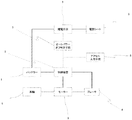
以下、本発明の実施形態を図面に基づいて詳細に説明する。図1に示すように、本発明の電動車はバッテリー1と、モーター3と、バッテリー1の電力をモーター3へ供給する制御装置2と、モーター3によって駆動される車輪5と、モーター3の回転軸を制動するブレーキ4と、電熱シート6と、電熱シート6へ電力を供給する継電手段7と、制御装置2へ動作信号を伝えるアクセル8と、アクセル8からの信号が一定時間無い場合継電手段7を切断制御するオートパワーオフ判定手段9を備えている。
【0008】
使用者がアクセル8を操作し、操作信号が制御装置2に入力されると、制御装置2はバッテリー1の電力をモーター3に供給する。このとき、ブレーキ4は制御装置2の信号によりモーター3の回転軸の制動が解除され、モーター3の回転により
車輪5が駆動され電動車は走行を始める。この様にブレーキ4は、電動車が走行しないときは制動し、走行する際にモーター3へ電力が供給されるときは制動を解除する。
【0009】
このとき、オートパワーオフ判定手段9は使用者が乗車していると判定し、継電手段7を接続制御し、電熱シート6へ電力が供給されシートが暖められる。
【0010】
一方、使用者が電動車を離れた場合、アクセルの操作はなくなりその状態で一定時間が経過すると、オートパワーオフ判定手段9は使用者が電動車から離れたと判定し、継電手段7を切断制御し、電熱シート6への電力を停止、電力の浪費を防止する。
【0011】
また、一般の電動車には内蔵されているバッテリー電圧測定手段を用い、バッテリー1の残容量が少ない場合は、オートパワーオフ判定に関わらず継電手段7を切断制御し、電熱シート6への電力を停止させ、バッテリー電力の使い切りを防止することもできる。
【0012】
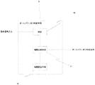
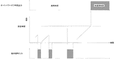
オート−パワーオフ判定手段9の動作の説明をする。オートパワーオフ判定手段9は、図2に示すように時計10と、時間比較手段11と、時間設定手段12を設け、アクセルなどの動作信号が入力されたとき時計10をゼロに戻し、動作信号が無くなると時計10の計時を開始する。通常、電動車が使用されている状態では図3に示すように動作信号が次々と入力され、時計10の計時はあまり進まないままゼロに戻されるということを繰り返す。この間、時計10の時間は時間設定手段12の時間より少ないため時間比較手段11より電動車が使用状態であることを出力する。しかし、使用者が電動車を離れた場合など電動車が使用されない状態になると、時計10の計時は進み、やがて時間設定手段12に設定された時間、例えば5分に達することで時間比較手段11によって電動車が未使用状態であることを出力する。
【0013】
オートパワーオフ判定手段9の替わりに、電動車本体の電源スイッチ、例えばキースイッチなどと連動して電熱シート6への電力を接続、切断することでも同様の効果を得られる。この場合は、電源スイッチ内部に継電機能を持たせても良いし、電源スイッチはそのままでその出力を継電手段7に与え電源制御しても良い。
【0014】
アクセル入力信号の替わりに、モーター3の動作状態を監視し、それを動作信号としてオートパワーオフ判定手段9に入力しても同様の効果が得られる。監視する方法としては、モーター端子電圧を電圧測定手段で測定し、モーター3が動作しているときはモーター端子電圧がゼロでない電圧になることを検出すればよい。
【0015】
また、モーター3が動作しているときブレーキ4は制動解除する事を利用して、ブレーキ4の制御信号を監視し、動作信号として入力することでオートパワーオフ判定してもよい。
【0016】
一方、シート内部に感圧手段を設け、直接使用者の着座を検知し、直接継電手段7を制御しても同様の効果を得られる。この場合、感圧手段としてはゴム製の感圧スイッチや一般的な押しボタンスイッチを使用してもよい。
【0017】
電熱シート6が何らかの原因で過熱した場合、回路切断し温度の異常上昇を防止するために継電手段7とは別に温度ヒューズを設けてもよい。
【0018】
電熱シート6の発熱部分は、一般的には座面部だけであるが、これに限らず背面部、ふくらはぎ部、側面部などを含めて身体全体を暖めても良い。この場合、温度ヒューズは各部分独立して設けることが望ましい。
【0019】
【発明の効果】本発明によれば、電動車においてシートを暖める電熱シートを、未使用時の電力浪費を自動で防ぐことにより、バッテリー上がりによる立ち往生や、使用者の電熱シートの電源管理負担を開放することができ、安心して暖かいシートを利用することができる。
【図面の簡単な説明】
【図1】本発明の実施例の形態に係る電動車の構成図
【図2】オートパワーオフ判定手段の構成図
【図3】オートパワーオフ判定手段の動作の流れ図
【符号の説明】
1 バッテリー
2 制御装置
3 モーター
4 ブレーキ
5 車輪
6 電熱シート
7 継電手段
8 アクセル入力手段
9 オートパワーオフ判定手段
10 時計
11 時間比較手段
12 時間設定手段[0001]
BACKGROUND OF THE INVENTION 1. Field of the Invention The present invention relates to power control of an electric heating seat of an electric vehicle.
[0002]
2. Description of the Related Art A general electric vehicle currently on the market has a built-in battery and uses all the power of the battery as a source of all operations. Electric heating sheets are available on the market that draw electric power from the battery and operate a built-in heater to heat the seat. With this electric heating seat, you can get on the electric car warmly even in cold seasons such as winter.
[0003]
However, the power consumption of the electric heating sheet is not small, and there is a possibility that the power of the battery is significantly consumed depending on the method of use. Therefore, it is necessary to provide a power switch or the like on the electric heating sheet and turn off the power except when necessary. However, when the user leaves the seat or the like, the user does not know that the electric heating sheet is operating only by looking at it, so that it is often possible to forget to turn off the power. In this case, when the user notices, the power of the battery is wasted, and in the worst case, the motor cannot be driven and the user may get stuck, which may give the user a very inconvenient feeling.
[0004]
In addition, even when the user does not forget to turn off the power supply of the electric heating sheet, the user pays attention to the operation of the power supply and gives a burden to the user, paying attention to the rising of the battery.
[0005]
SUMMARY OF THE INVENTION An object of the present invention is to provide an electric vehicle for automatically controlling the power supply of an electric heating sheet.
[0006]
[Means for Solving the Problems]
In order to achieve the above object, a battery, a motor for driving wheels, a brake for braking the motor, a control device for supplying power from the battery to the motor, and accelerator input means for providing a signal to the control device The electric vehicle having an electric heating sheet for warming the seat and a relay means for controlling the supply of electric power from the battery to the electric heating sheet does not receive a signal from the accelerator input means for a certain period of time. Automatic power-off determining means for determining that use of the vehicle has been interrupted, and controlling the relay means by the automatic power-off determining means, so that when a user leaves the electric vehicle and a certain time elapses, the electric heating sheet is automatically transferred to the electric heating sheet. Power is cut off, and waste of power can be prevented.
[0007]
BEST MODE FOR CARRYING OUT THE INVENTION
Hereinafter, embodiments of the present invention will be described in detail with reference to the drawings. As shown in FIG. 1, the electric vehicle according to the present invention includes a battery 1, a motor 3, a control device 2 for supplying electric power of the battery 1 to the motor 3, wheels 5 driven by the motor 3, and rotation of the motor 3. A brake 4 for braking the shaft, an electric heating sheet 6, a relay means 7 for supplying electric power to the electric heating sheet 6, an accelerator 8 for transmitting an operation signal to the control device 2, and a relay when there is no signal from the accelerator 8 for a predetermined time. An automatic power-off determining means 9 for controlling the disconnection of the power means 7 is provided.
[0008]
When the user operates the accelerator 8 and an operation signal is input to the control device 2, the control device 2 supplies the electric power of the battery 1 to the motor 3. At this time, the brake of the rotating shaft of the motor 3 is released by the signal of the control device 2 of the brake 4, and the rotation of the motor 3 drives the wheels 5, and the electric vehicle starts running. As described above, the brake 4 brakes when the electric vehicle does not travel, and releases the braking when power is supplied to the motor 3 when traveling.
[0009]
At this time, the automatic power-off determining means 9 determines that the user is in the vehicle, controls the connection of the relay means 7, and supplies power to the electric heating sheet 6 to warm the seat.
[0010]
On the other hand, when the user leaves the electric vehicle, the operation of the accelerator stops, and after a certain period of time has elapsed, the auto power-off determining means 9 determines that the user has left the electric vehicle and disconnects the relay means 7. It controls and stops electric power to the electric heating sheet 6 to prevent waste of electric power.
[0011]
When the remaining capacity of the battery 1 is small, the relay unit 7 is controlled to be cut off regardless of the auto power-off determination. Power can also be turned off to prevent running out of battery power.
[0012]
The operation of the auto-power-off determining means 9 will be described. As shown in FIG. 2, the automatic power-off determining means 9 includes a clock 10, a time comparing means 11, and a time setting means 12, and returns the clock 10 to zero when an operation signal such as an accelerator is inputted, When there is no more, the clock of the clock 10 starts. Normally, in the state where the electric vehicle is used, the operation signals are successively input as shown in FIG. 3, and the time of the timepiece 10 is returned to zero without progressing much. During this time, since the time of the clock 10 is shorter than the time of the time setting means 12, the time comparing means 11 outputs that the electric vehicle is in use. However, when the electric vehicle is not used, for example, when the user leaves the electric vehicle, the clock of the clock 10 advances, and eventually reaches the time set in the time setting unit 12, for example, 5 minutes. Output that the electric vehicle is in an unused state.
[0013]
The same effect can be obtained by connecting and disconnecting electric power to the electric heating sheet 6 in conjunction with a power switch of the electric vehicle body, for example, a key switch or the like, instead of the automatic power-off determining means 9. In this case, a power relay function may be provided inside the power switch, or the output of the power switch may be provided to the relay means 7 as it is to control the power.
[0014]
The same effect can be obtained by monitoring the operating state of the motor 3 instead of the accelerator input signal and inputting it to the auto power-off determining means 9 as an operating signal. As a monitoring method, the motor terminal voltage may be measured by the voltage measuring means, and it may be detected that the motor terminal voltage becomes a non-zero voltage when the motor 3 is operating.
[0015]
In addition, utilizing the fact that the brake 4 is released when the motor 3 is operating, the control signal of the brake 4 may be monitored, and the automatic power-off determination may be made by inputting the control signal as an operation signal.
[0016]
On the other hand, the same effect can be obtained by providing pressure sensing means inside the seat, directly detecting the seating of the user, and controlling the direct relay means 7. In this case, a rubber pressure-sensitive switch or a general push button switch may be used as the pressure-sensitive means.
[0017]
If the electric heating sheet 6 is overheated for some reason, a temperature fuse may be provided separately from the relay means 7 in order to cut the circuit and prevent an abnormal rise in temperature.
[0018]
The heat generating portion of the electric heating sheet 6 is generally only the seat surface portion, but the present invention is not limited to this, and the entire body including the back surface portion, the calf portion, and the side portion may be warmed. In this case, it is desirable to provide the thermal fuse independently for each part.
[0019]
According to the present invention, an electric heating seat for warming a seat in an electric vehicle is automatically prevented from wasting power when not in use. It can be opened and a warm seat can be used with confidence.
[Brief description of the drawings]
FIG. 1 is a configuration diagram of an electric vehicle according to an embodiment of the present invention. FIG. 2 is a configuration diagram of an auto power-off determination unit. FIG. 3 is a flowchart of the operation of the auto power-off determination unit.
DESCRIPTION OF SYMBOLS 1 Battery 2 Control device 3 Motor 4 Brake 5 Wheel 6 Electric heating sheet 7 Relay means 8 Accelerator input means 9 Auto power-off determination means 10 Clock 11 Time comparison means 12 Time setting means