JP2004165165A - Spark plug - Google Patents
Spark plug Download PDFInfo
- Publication number
- JP2004165165A JP2004165165A JP2003383388A JP2003383388A JP2004165165A JP 2004165165 A JP2004165165 A JP 2004165165A JP 2003383388 A JP2003383388 A JP 2003383388A JP 2003383388 A JP2003383388 A JP 2003383388A JP 2004165165 A JP2004165165 A JP 2004165165A
- Authority
- JP
- Japan
- Prior art keywords
- electrode
- spark plug
- weight
- content
- section
- Prior art date
- Legal status (The legal status is an assumption and is not a legal conclusion. Google has not performed a legal analysis and makes no representation as to the accuracy of the status listed.)
- Pending
Links
Images


Classifications
-
- H—ELECTRICITY
- H01—ELECTRIC ELEMENTS
- H01T—SPARK GAPS; OVERVOLTAGE ARRESTERS USING SPARK GAPS; SPARKING PLUGS; CORONA DEVICES; GENERATING IONS TO BE INTRODUCED INTO NON-ENCLOSED GASES
- H01T13/00—Sparking plugs
- H01T13/20—Sparking plugs characterised by features of the electrodes or insulation
- H01T13/39—Selection of materials for electrodes
Abstract
Description
本発明は、請求項1および請求項7の上位概念部に記載の形式の点火プラグ、すなわち電極を備えた点火プラグであって、電極の一方の端区分に電極区分が設けられている形式のものに関する。 The invention relates to a spark plug of the type described in the preamble of claim 1 and claim 7, that is to say a spark plug with electrodes, wherein the electrode section is provided at one end section of the electrode. About things.
このような形式の点火プラグは、たとえばドイツ連邦共和国特許出願公開第10015642号明細書に記載されている。この点火プラグは中心電極と接地電極とを有しており、両電極の間には、電圧を印加することによって火花ギャップが形成される。電極は電極ベースボディを有しており、この電極ベースボディには、高い耐損耗性の範囲を形成する電極区分が固定されている。電極ベースボディは主としてニッケルから成っていて、銅から成る熱伝導性のコアを有していてよい。前記電極区分は、元素イリジウムおよびニッケルを含有する合金から成っている。前記電極区分はレーザ溶接、抵抗溶接またはろう接によって電極ベースボディに被着される。 A spark plug of this type is described, for example, in DE 10015642 A1. The spark plug has a center electrode and a ground electrode, and a spark gap is formed between the two electrodes by applying a voltage. The electrode has an electrode base body, on which electrode sections forming a high wear-resistant range are fixed. The electrode base body is mainly made of nickel and may have a thermally conductive core made of copper. Said electrode section consists of an alloy containing the elements iridium and nickel. The electrode sections are applied to the electrode base body by laser welding, resistance welding or brazing.
このような点火プラグでは、電極ベースボディへの電極区分の被着時、特に溶接による被着時またはエンジン内での使用時に、前記電極区分と電極ベースボディとの間に高い熱機械的な応力が発生するという不都合がある。
本発明の課題は、冒頭で述べた形式の点火プラグを改良して、前記電極区分と電極ベースボディとの間に極めて僅かな熱機械的な応力しか生じず、しかも廉価に製造可能となるような点火プラグを提供することである。 The object of the invention is to improve a spark plug of the type mentioned at the outset in such a way that very little thermomechanical stresses occur between the electrode section and the electrode base body and can be manufactured inexpensively. It is to provide a simple spark plug.
この課題を解決するために本発明の第1の構成では、前記電極区分が、銅を含有した合金を有しているようにした。 In order to solve this problem, in the first configuration of the present invention, the electrode section has an alloy containing copper.
上記課題を解決するために本発明の第2の構成では、前記電極区分が、白金とロジウムとを含有した合金を有しているようにした。 In order to solve the above problem, in the second configuration of the present invention, the electrode section has an alloy containing platinum and rhodium.
本発明による点火プラグには、次のような利点がある。すなわち、前記電極区分と電極ベースボディとの間に極めて僅かな熱機械的な応力しか生じないように前記電極区分の材料が選択されており、前記電極区分が特に高い耐摩耗性を有している。さらに、貴金属含量を減少させることによってコスト節約を達成することができる。 The spark plug according to the present invention has the following advantages. That is, the material of the electrode section is selected such that only very little thermomechanical stress occurs between the electrode section and the electrode base body, and the electrode section has a particularly high wear resistance. I have. In addition, cost savings can be achieved by reducing the noble metal content.
請求項2〜請求項6ならびに請求項8以下に記載の手段により、請求項1および請求項7に記載の点火プラグの有利な構成および改良が可能となる。 Advantageous configurations and improvements of the spark plugs according to the first and seventh aspects are enabled by the means described in the second to sixth aspects and the eighth aspect and the following aspects.
結合されるべき材料が同程度の熱膨張率および低い弾性率を有していると、熱機械的な応力を最小限に抑えることができる。特許請求の範囲に記載の組成は、電極ベースボディの材料に対する前記電極区分の材料の最適な適合を可能にする。 Thermomechanical stresses can be minimized if the materials to be joined have comparable coefficients of thermal expansion and low modulus. The claimed composition allows an optimal adaptation of the material of the electrode section to the material of the electrode base body.
前記電極区分が、60〜99質量%の白金含量と、1〜40質量%の銅含量とを有している場合または前記電極区分が、30〜89質量%の白金含量と、1〜40質量%の銅含量と、10〜30質量%のロジウム含量とを有している場合または前記電極区分が、30〜98質量%の白金含量と、1〜40質量%の銅含量と、1〜30質量%のイリジウム含量とを有している場合には、特に僅かな熱機械的な応力しか生じなくなる。また、70〜95質量%の白金含量と、5〜30質量%のロジウム含量とを有しているか、または30〜94質量%の白金含量と、5〜30質量%のロジウム含量と、1〜40質量%のニッケル含量とを有しているか、または30〜94質量%の白金含量と、5〜30質量%のロジウム含量と、1〜40質量%のイリジウム含量とを有している前記電極区分も特に適している。 When the electrode segment has a platinum content of 60-99% by mass and a copper content of 1-40% by mass, or the electrode segment has a platinum content of 30-89% by mass and 1-40% by mass. % Or a rhodium content of 10 to 30% by weight or the electrode section has a platinum content of 30 to 98% by weight, a copper content of 1 to 40% by weight, With an iridium content of 5% by weight, only small thermomechanical stresses occur. It also has a platinum content of 70 to 95% by weight and a rhodium content of 5 to 30% by weight, or a platinum content of 30 to 94% by weight, a rhodium content of 5 to 30% by weight, Said electrode having a nickel content of 40% by weight or a platinum content of 30 to 94% by weight, a rhodium content of 5 to 30% by weight and an iridium content of 1 to 40% by weight Segmentation is also particularly suitable.
前記電極区分が、付加的にイットリウム、ジルコニウム、ハフニウム、チタン、タンタル、タングステン、オスミウム、ルテニウム、金、銀およびパラジウムのグループからの1種の金属または酸化物または数種の金属または酸化物を、それぞれ最大1質量%までの含量で含有していると有利である。この手段により、特に高い温度における前記電極区分の合金の機械的な強度が高められる。 The electrode section additionally comprises one or more metals or oxides from the group of yttrium, zirconium, hafnium, titanium, tantalum, tungsten, osmium, ruthenium, gold, silver and palladium; It is advantageous if they are contained in amounts of up to 1% by weight in each case. By this measure, the mechanical strength of the alloy of the electrode section, especially at high temperatures, is increased.
以下に、本発明を実施するための最良の形態を図面につき詳しく説明する。 Hereinafter, the best mode for carrying out the present invention will be described in detail with reference to the drawings.
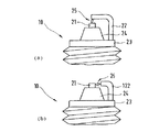
点火プラグの原理的な構造および機能形式は、公知先行技術から十分に知られており、たとえば「Bosch−technischen Unterrichtung−Zuendkerzen」(Robert Bosch GmbH、1985年)から知ることができる。図1(a)および(b)には、本発明の第1実施例および第2実施例として、点火プラグ10の燃焼室側の端部が概略的に側面図で示されている。点火プラグ10は金属製の管状のハウジング23を有しており、このハウジング23は、ほぼ半径方向対称的に形成されている。金属製のハウジング23の対称軸線に沿って設けられた中心の孔内には、同軸的に延びる絶縁体24が配置されている。この絶縁体24の長手方向軸線に沿って設けられた中心の孔内には、燃焼室側の端部で中心電極21が配置されている。この中心電極21は第1実施例および第2実施例では、絶縁体24の燃焼室側の端部で前記孔から突出している。図示していない別の実施例では、中心電極21が絶縁体24の孔から突出しないように配置されていてもよい。
The basic structure and mode of operation of spark plugs are well known from the prior art and can be found, for example, in "Bosch-technischen Unterrichtung-Zendkerzen" (Robert Bosch GmbH, 1985). FIGS. 1A and 1B schematically show a combustion chamber side end of a
中心電極21の、燃焼室から遠い方の端部では、絶縁体24に設けられた前記孔内に導電性のガラス溶融体(図示しない)が配置されている。このガラス溶融体は中心電極21を、同じく絶縁体24の中心の孔内に配置されている接続ピン(図示しない)に接続している。金属製のハウジング23の燃焼室側の端部には、少なくともさらに1つの接地電極22,122が配置されている。この接地電極22,122は、まずハウジング23から出発して、ハウジング23の対称軸線に対して平行に延び、それからハウジング23の対称軸線へ向かってほぼ直角に折り曲げられている。前記接続ピンと、導電性のガラス溶融体と、中心電極21とを介して点火プラグ10の燃焼室側の端部へ到達する電気的なエネルギにより、火花ギャップ25に沿って中心電極21と接地電極22,122との間に火花が発生させられる。この場合、火花は燃焼室内に存在する空気・燃料混合物に点火する。図2の(a)、(b)、(c)および(d)ならびに図4の(a)、(b)および(c)には、中心電極21の種々の実施例が詳細に図示されている。図3の(a)、(b)および(c)ならびに図5の(a)、(b)、(c)および(d)には、接地電極22,122の種々の実施例が詳細に図示されている。
At the end of the
図1の(a)に示した第1実施例と、図1の(b)に示した第2実施例とは、接地電極22,122の設計の点で互いに異なっている。第1実施例では、接地電極22が「屋根形電極」として形成されており、この場合、接地電極22は中心電極21の端面の上方にまで延びて接地電極22を屋根状に覆っている。火花ギャップ25は、屋根形電極として形成された接地電極22の場合にはハウジング23および絶縁体24の対称軸線の範囲に位置していて、中心電極21の端面と接地電極22の端区分との間に延びている。第2実施例では、接地電極122がハウジング23の対称軸線にまで延びていない。接地電極122の、中心電極21に面した端区分は、中心電極21の側方に並んで配置されていて、中心電極21の外周面へ向けられている。したがって、接地電極122は中心電極21の端面を超えて突出していないか、または少しだけしか突出していない。これに相応して、第2実施例の火花ギャップ25は中心電極21の側方の外周面と接地電極122の端面との間に形成される。
The first embodiment shown in FIG. 1A is different from the second embodiment shown in FIG. 1B in the design of the
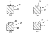
図2の(a)、(b)、(c)および(d)には、中心電極21の燃焼室側の端部の種々の実施例が横断面図で示されている。これらの実施例は特に第1実施例による点火プラグ10のために適している。中心電極21は電極ベースボディ32を有しており、この電極ベースボディ32の燃焼室側の端部には電極区分31が配置されている。この電極区分31は火花放電による火花浸食および腐食に対する高い耐性によりすぐれているので、点火プラグの長い機能時間が保証されている。電極区分31はこの場合、火花ギャップ25の一端を形成しているので、火花は直接に中心電極21の電極区分31の範囲で閃絡する。
2 (a), 2 (b), 2 (c) and 2 (d) show various embodiments of the end portion of the
図2の(a)、(b)、(c)および(d)に示した種々の実施例は、電極ベースボディ32における電極区分31の配置の点で互いに異なっている。図2(a)に示した実施例では、電極区分31が電極ベースボディ32の、燃焼室に面した側の端面を完全に覆っているので、電極区分31と電極ベースボディ32とは少なくとも電極区分31と電極ベースボディ32との間の移行範囲において同一の直径を有している。図2(b)に示した実施例では、円筒状の電極区分31が電極ベースボディ32の端面に真ん中で被着されており、この場合、電極区分31の直径は電極ベースボディ32の直径よりも小さく形成されている。図2(c)に示した中心電極21では、電極区分31が電極ベースボディ32の火花ギャップ側の端面を越えて電極ベースボディ32内に突入している。図2(d)に示した実施例では、電極区分31が電極ベースボディ32内に突入しており、この場合、電極区分31の、火花ギャップに面した側の端面と、電極ベースボディ32の、火花ギャップに面した側の端面とは同一平面に位置している。
The different embodiments shown in FIGS. 2A, 2B, 2C and 2D differ from one another in the arrangement of the
図3の(a)、(b)および(c)には、特に図1(a)に示した本発明の実施例のために特に適している接地電極22の燃焼室側の端区分の種々の実施例が示されている。この接地電極22は電極ベースボディ42を有しており、この電極ベースボディ42の、中心電極21に面した側には、電極区分41が設けられている。図3の(a)、(b)および(c)に示した実施例は、電極ベースボディ42における電極区分41の配置の点で互いに異なっている。図3(a)に示した実施例では、電極区分41が電極ベースボディ42の外部に設けられている。それに対して図3(c)に示した実施例では、電極区分41が、電極ベースボディ42に設けられた切欠き内に配置されており、しかも電極ベースボディ42の輪郭面を越えて突出していない。図3(b)に示した実施例では、電極区分41が図3(c)の場合と同様に、電極ベースボディ42に設けられた切欠き内に配置されているが、しかし図3(c)の場合とは異なり電極ベースボディ42から突出している。
FIGS. 3a, 3b and 3c show various combustion chamber-side end sections of the
図4の(a)、(b)および(c)には、中心電極21の燃焼室側の端部の別の2つの実施例が示されている。これらの実施例は、特に第2実施例による点火プラグ10のために適している。中心電極21は電極ベースボディ52を有している。この電極ベースボディ52には、電極区分51が配置されており、この電極区分51は火花浸食および腐食に対する高い耐性を有している。電極区分51は中空円筒状の形状を有していて、電極ベースボディ52に設けられた切欠き内に嵌め込まれている。したがって、電極区分51は中心電極21の外周面もしくは輪郭面の1区分を形成している。図4の(a)および(c)に示した両実施例は次の点で互いに異なっている。すなわち、図4(a)に示した実施例では、電極区分51が中心電極21の端面にまで到達しており、それに対して図4(c)に示した実施例では、中心電極21に設けられた、電極区分51が配置された切欠きが、中心電極21の端面にまで到達していない。本発明のさらに別の実施例(図示しない)は、図4の(a)、(b)および(c)に示した実施例とは次の点で異なっている。すなわち、この実施例では、電極区分51が電極ベースボディ52の輪郭面を越えて突出しており、これにより電極区分51の直径は電極ベースボディ52の直径よりも大きく形成されている。
FIGS. 4A, 4B and 4C show two other embodiments of the end of the
図5の(a)、(b)、(c)および(d)には、特に図1(b)に示した本発明の実施例のために適している接地電極122の別の実施例が示されている。接地電極122はやはり電極ベースボディ132を有しており、この電極ベースボディ132には、火花浸食および腐食に対する高い耐性を有している電極区分131が配置されている。図5の(a)、(b)、(c)および(d)に示した実施例は、ジオメトリ的な構成の点では図2の(a)、(b)、(c)および(d)に示した実施例に相当しているので、詳しい説明は省略する。
FIGS. 5 (a), (b), (c) and (d) show another embodiment of a
中心電極21の電極ベースボディ32,52ならびに接地電極22,122の電極ベースボディ42,132は、主としてニッケルまたはニッケル合金から成っていて、たいていは銅コアを有している。この銅コアにより、良好な熱伝導が保証されている。
The
電極区分31,41,51,131は、プレート、ピンまたは平らに押し潰されたボールとして、レーザ溶接によって電極ベースボディ32,42,52,132に被着される。電極区分31,41,51,131と電極ベースボディ32,42,52,132とを結合するためには、拡散溶接または抵抗溶接も適している。電極区分31,41,51,131を電極ベースボディ32,42,52,132と溶接する場合には、高い温度が発生し、この高い温度に基づき、材料に高い熱機械的な応力(thermomechanisch.Spannungen)が生ぜしめられる。エンジンにおける使用時でも、最大1000℃までの高い温度が発生し、この温度は短時間で400℃にまで冷却し得る。このことは、熱膨張率差および電極区分31,41,51,131および電極ベースボディ32,42,52,132の材料の弾性率(Eモジュール)の絶対値に対して比例する熱機械的な応力を生ぜしめる。
The
電極区分31,41,51,131の材料のための以下に挙げる各構成では、僅かな熱機械的な応力しか生じないように材料組成が選択されている。
In the following configurations for the materials of the
電極区分31,41,51,131の材料の第1の構成:
白金:96質量%
銅:4%
電極区分31,41,51,131の材料の第2の構成:
白金:80質量%
銅:10質量%
ロジウム:10質量%
電極区分31,41,51,131の材料の第3の構成:
白金:70質量%
銅:10質量%
イリジウム:20質量%
電極区分31,41,51,131の材料の第4の構成:
白金85質量%
ロジウム15質量%
電極区分31,41,51,131の材料の第5の構成:
白金:65質量%
ロジウム:15質量%
イリジウム:20質量%
電極区分31,41,51,131の材料の第6の構成:
白金:65質量%
ロジウム:15質量%
ニッケル20質量%。
First configuration of the material of the
Platinum: 96% by mass
Copper: 4%
A second configuration of the material of the
Platinum: 80% by mass
Copper: 10% by mass
Rhodium: 10% by mass
Third configuration of the material of the
Platinum: 70% by mass
Copper: 10% by mass
Iridium: 20% by mass
Fourth configuration of the material of the
85% by mass of platinum
Rhodium 15% by mass
Fifth configuration of the material of the
Platinum: 65% by mass
Rhodium: 15% by mass
Iridium: 20% by mass
Sixth configuration of the material of the
Platinum: 65% by mass
Rhodium: 15% by mass
Nickel 20% by mass.
図6には、白金(Pt)から成る電極区分31,41,51,131と、96質量%の白金含量と4質量%の銅含量とから成る(Pt+Cu)電極区分31,41,51,131とに関して、摩耗体積V(mm3)が運転時間t(時間)の関数として描かれている。図6の線図から判るように、第1の構成(Pt+Cu)の組成を有する電極区分31,41,51,131は、純粋な白金から成る電極区分31,41,51,131よりも著しく少ない摩耗を示している。
FIG. 6 shows
電極区分31,41,51,131は上で挙げた材料に対して付加的に、イットリウム、ジルコニウム、ハフニウム、チタン、タンタル、タングステン、オスミウム、ルテニウム、金、銀およびパラジウムのグループからの1種の金属または酸化物または数種の金属または酸化物を、それぞれ最大1質量%までの含量で含有していてよい。
The
10 点火プラグ
21 中心電極
22 接地電極
23 ハウジング
24 絶縁体
25 火花ギャップ
31 電極区分
32 電極ベースボディ
41 電極区分
42 電極ベースボディ
51 電極区分
52 電極ベースボディ
131 電極区分
132 電極ベースボディ
DESCRIPTION OF
Claims (15)
Applications Claiming Priority (1)
| Application Number | Priority Date | Filing Date | Title |
|---|---|---|---|
| DE10252736A DE10252736B4 (en) | 2002-11-13 | 2002-11-13 | spark plug |
Publications (1)
| Publication Number | Publication Date |
|---|---|
| JP2004165165A true JP2004165165A (en) | 2004-06-10 |
Family
ID=32239999
Family Applications (1)
| Application Number | Title | Priority Date | Filing Date |
|---|---|---|---|
| JP2003383388A Pending JP2004165165A (en) | 2002-11-13 | 2003-11-13 | Spark plug |
Country Status (3)
| Country | Link |
|---|---|
| US (1) | US20040140745A1 (en) |
| JP (1) | JP2004165165A (en) |
| DE (1) | DE10252736B4 (en) |
Cited By (8)
| Publication number | Priority date | Publication date | Assignee | Title |
|---|---|---|---|---|
| JP2008198545A (en) * | 2007-02-15 | 2008-08-28 | Ngk Spark Plug Co Ltd | Spark plug for internal combustion engine |
| JP2009037750A (en) * | 2007-07-31 | 2009-02-19 | Denso Corp | Spark plug for internal combustion engines |
| JP2009070810A (en) * | 2007-08-23 | 2009-04-02 | Ngk Spark Plug Co Ltd | Spark plug for internal combustion engine |
| WO2011102355A1 (en) * | 2010-02-17 | 2011-08-25 | 田中貴金属工業株式会社 | Spark plug electrode material having excellent spark consumption resistance and excellent discharge characteristics |
| WO2011155509A1 (en) * | 2010-06-11 | 2011-12-15 | 田中貴金属工業株式会社 | Material for spark plug electrode with excellent spark wear resistance |
| WO2011155101A1 (en) | 2010-06-11 | 2011-12-15 | 日本特殊陶業株式会社 | Spark plug |
| KR101353670B1 (en) | 2007-02-21 | 2014-01-20 | 세이코 인스트루 가부시키가이샤 | Triangular wave generation circuit |
| JP2017152360A (en) * | 2015-12-15 | 2017-08-31 | フェデラル モーグル イグニッション ゲーエムベーハーFederal−Mogul Ignition GmbH | Spark plug |
Families Citing this family (18)
| Publication number | Priority date | Publication date | Assignee | Title |
|---|---|---|---|---|
| EP1677400B1 (en) * | 2004-12-28 | 2019-01-23 | Ngk Spark Plug Co., Ltd | Spark plug |
| DE102006009790A1 (en) * | 2006-03-01 | 2007-09-06 | Beru Ag | Reinforcing method for sheathing a central electrode (CE) in a spark plug for internal combustion engines uses a spark point of metal material capable of greater wear than the CE's other material |
| EP2012397B1 (en) * | 2007-07-06 | 2016-08-24 | Federal-Mogul Ignition GmbH | Spark plug and method for its production |
| US8030830B2 (en) | 2007-11-15 | 2011-10-04 | Fram Group Ip Llc | Iridium alloy for spark plug electrodes |
| EP2599172A4 (en) | 2010-07-29 | 2013-12-25 | Federal Mogul Ignition Co | Electrode material for use with a spark plug |
| US8471451B2 (en) | 2011-01-05 | 2013-06-25 | Federal-Mogul Ignition Company | Ruthenium-based electrode material for a spark plug |
| DE112012000600B4 (en) | 2011-01-27 | 2018-12-13 | Federal-Mogul Ignition Company | A spark plug electrode for a spark plug, spark plug, and method of manufacturing a spark plug electrode |
| DE112012000947B4 (en) | 2011-02-22 | 2018-03-22 | Federal-Mogul Ignition Company | Method for producing an electrode material for a spark plug |
| DE112012002699B4 (en) | 2011-06-28 | 2018-12-13 | Federal-Mogul Ignition Company | Spark plug and method of manufacturing an electrode of a spark plug |
| US20140184054A1 (en) * | 2011-07-28 | 2014-07-03 | Tanaka Kikinzoku Kogyo K.K. | Clad Electrode for Spark Plug and Method For Manufacturing Same |
| US10044172B2 (en) | 2012-04-27 | 2018-08-07 | Federal-Mogul Ignition Company | Electrode for spark plug comprising ruthenium-based material |
| DE112013002619B4 (en) | 2012-05-22 | 2018-12-27 | Federal-Mogul Ignition Company | Method for producing an electrode material |
| US8979606B2 (en) | 2012-06-26 | 2015-03-17 | Federal-Mogul Ignition Company | Method of manufacturing a ruthenium-based spark plug electrode material into a desired form and a ruthenium-based material for use in a spark plug |
| US9231380B2 (en) | 2012-07-16 | 2016-01-05 | Federal-Mogul Ignition Company | Electrode material for a spark plug |
| DE102015100835A1 (en) | 2015-01-21 | 2015-12-31 | Federal-Mogul Ignition Gmbh | spark plug |
| WO2022040544A1 (en) * | 2020-08-21 | 2022-02-24 | Federal-Mogul Ignition Llc | Spark plug electrode and method of manufacturing the same |
| WO2022234492A1 (en) | 2021-05-04 | 2022-11-10 | Federal-Mogul Ignition Gmbh | Spark plug electrode and method of manufacturing the same |
| US11831130B2 (en) | 2022-03-29 | 2023-11-28 | Federal-Mogul Ignition Gmbh | Spark plug, spark plug electrode, and method of manufacturing the same |
Family Cites Families (12)
| Publication number | Priority date | Publication date | Assignee | Title |
|---|---|---|---|---|
| US2239561A (en) * | 1939-01-19 | 1941-04-22 | Baker & Co Inc | Spark plug |
| US4771209B1 (en) * | 1979-10-22 | 1996-05-14 | Champion Spark Plug Co | Spark igniter having precious metal ground electrode inserts |
| ZA805008B (en) * | 1979-10-22 | 1981-08-26 | Champion Spark Plug Co | Spark igniter |
| JPS59160988A (en) * | 1983-03-02 | 1984-09-11 | 日本特殊陶業株式会社 | Spark plug |
| DE4431143B4 (en) * | 1994-09-01 | 2004-09-23 | Robert Bosch Gmbh | Spark plug for an internal combustion engine |
| JPH1197151A (en) * | 1997-09-17 | 1999-04-09 | Ngk Spark Plug Co Ltd | Spark plug |
| US6045424A (en) * | 1998-07-13 | 2000-04-04 | Alliedsignal Inc. | Spark plug tip having platinum based alloys |
| US6412465B1 (en) * | 2000-07-27 | 2002-07-02 | Federal-Mogul World Wide, Inc. | Ignition device having a firing tip formed from a yttrium-stabilized platinum-tungsten alloy |
| JP4305713B2 (en) * | 2000-12-04 | 2009-07-29 | 株式会社デンソー | Spark plug |
| JP3702838B2 (en) * | 2001-02-08 | 2005-10-05 | 株式会社デンソー | Spark plug and manufacturing method thereof |
| JP4271379B2 (en) * | 2001-02-08 | 2009-06-03 | 株式会社デンソー | Spark plug |
| US6664719B2 (en) * | 2001-03-28 | 2003-12-16 | Ngk Spark Plug Co., Ltd. | Spark plug |
-
2002
- 2002-11-13 DE DE10252736A patent/DE10252736B4/en not_active Expired - Fee Related
-
2003
- 2003-11-13 US US10/712,552 patent/US20040140745A1/en not_active Abandoned
- 2003-11-13 JP JP2003383388A patent/JP2004165165A/en active Pending
Cited By (15)
| Publication number | Priority date | Publication date | Assignee | Title |
|---|---|---|---|---|
| JP2008198545A (en) * | 2007-02-15 | 2008-08-28 | Ngk Spark Plug Co Ltd | Spark plug for internal combustion engine |
| KR101353670B1 (en) | 2007-02-21 | 2014-01-20 | 세이코 인스트루 가부시키가이샤 | Triangular wave generation circuit |
| JP2009037750A (en) * | 2007-07-31 | 2009-02-19 | Denso Corp | Spark plug for internal combustion engines |
| JP2009070810A (en) * | 2007-08-23 | 2009-04-02 | Ngk Spark Plug Co Ltd | Spark plug for internal combustion engine |
| US8624472B2 (en) | 2007-08-23 | 2014-01-07 | Ngk Spark Plug Co., Ltd. | Spark plug for internal combustion engine |
| CN102754292A (en) * | 2010-02-17 | 2012-10-24 | 田中贵金属工业株式会社 | Material for ignition plug electrode excellent in durability to spark erosion and discharge characteristics |
| JP2011171037A (en) * | 2010-02-17 | 2011-09-01 | Tanaka Kikinzoku Kogyo Kk | Material for ignition plug electrode excellent in durability to spark erosion and discharge characteristics |
| WO2011102355A1 (en) * | 2010-02-17 | 2011-08-25 | 田中貴金属工業株式会社 | Spark plug electrode material having excellent spark consumption resistance and excellent discharge characteristics |
| WO2011155101A1 (en) | 2010-06-11 | 2011-12-15 | 日本特殊陶業株式会社 | Spark plug |
| JP2011258510A (en) * | 2010-06-11 | 2011-12-22 | Ngk Spark Plug Co Ltd | Spark plug |
| JP2011258486A (en) * | 2010-06-11 | 2011-12-22 | Ngk Spark Plug Co Ltd | Material for ignition plug electrode having excellent spark wear resistance |
| WO2011155509A1 (en) * | 2010-06-11 | 2011-12-15 | 田中貴金属工業株式会社 | Material for spark plug electrode with excellent spark wear resistance |
| US8618725B2 (en) | 2010-06-11 | 2013-12-31 | Ngk Spark Plug Co., Ltd. | Spark plug |
| KR101409547B1 (en) * | 2010-06-11 | 2014-06-19 | 니혼도꾸슈도교 가부시키가이샤 | Spark plug |
| JP2017152360A (en) * | 2015-12-15 | 2017-08-31 | フェデラル モーグル イグニッション ゲーエムベーハーFederal−Mogul Ignition GmbH | Spark plug |
Also Published As
| Publication number | Publication date |
|---|---|
| DE10252736A1 (en) | 2004-06-03 |
| DE10252736B4 (en) | 2004-09-23 |
| US20040140745A1 (en) | 2004-07-22 |
Similar Documents
| Publication | Publication Date | Title |
|---|---|---|
| JP2004165165A (en) | Spark plug | |
| JP5090170B2 (en) | Ignition system for an internal combustion engine | |
| US6094000A (en) | Spark plug for internal combustion engine | |
| US7449823B2 (en) | Spark plug with specific electrode material | |
| EP0377938B1 (en) | A spark plug structure | |
| EP1576707B1 (en) | Ignition device having an electrode formed from an iridium-based alloy | |
| EP1309053B1 (en) | Spark plug | |
| JP3902756B2 (en) | Spark plug | |
| MXPA06008753A (en) | Spark plug configuration having a noble metal tip. | |
| EP1517420A2 (en) | Spark plug and related manufacturing method | |
| JP5809673B2 (en) | Spark plug | |
| KR101168204B1 (en) | Ignition device having an electrode tip formed from an iridium-based alloy | |
| JP4295064B2 (en) | Spark plug | |
| GB2302367A (en) | I.c. engine spark plug with noble metal chip of Ir-Rh alloy | |
| US6971937B2 (en) | Method of manufacturing a spark plug for an internal combustion engine | |
| JP4070228B2 (en) | Manufacturing method of spark plug | |
| JP2002231411A (en) | Spark plug for internal combustion engine | |
| JP4834264B2 (en) | Spark plug | |
| US7268474B2 (en) | Alloy, electrode with the alloy, and ignition device with the alloy | |
| JPH097734A (en) | Side electrode type spark plug | |
| JP4435646B2 (en) | Spark plug | |
| JP6403643B2 (en) | Spark plug | |
| JPH09129357A (en) | Spark plug for internal combustion engine | |
| MX2007000942A (en) | Ignition device having an electrode tip formed from an iridium-based alloy | |
| JP2005100898A (en) | Spark plug for internal combustion engine |