JP2004163480A - Map preparation system and map management system - Google Patents
Map preparation system and map management system Download PDFInfo
- Publication number
- JP2004163480A JP2004163480A JP2002326259A JP2002326259A JP2004163480A JP 2004163480 A JP2004163480 A JP 2004163480A JP 2002326259 A JP2002326259 A JP 2002326259A JP 2002326259 A JP2002326259 A JP 2002326259A JP 2004163480 A JP2004163480 A JP 2004163480A
- Authority
- JP
- Japan
- Prior art keywords
- data
- map
- generation
- software
- management
- Prior art date
- Legal status (The legal status is an assumption and is not a legal conclusion. Google has not performed a legal analysis and makes no representation as to the accuracy of the status listed.)
- Pending
Links
Images


Classifications
-
- G—PHYSICS
- G09—EDUCATION; CRYPTOGRAPHY; DISPLAY; ADVERTISING; SEALS
- G09B—EDUCATIONAL OR DEMONSTRATION APPLIANCES; APPLIANCES FOR TEACHING, OR COMMUNICATING WITH, THE BLIND, DEAF OR MUTE; MODELS; PLANETARIA; GLOBES; MAPS; DIAGRAMS
- G09B29/00—Maps; Plans; Charts; Diagrams, e.g. route diagram
-
- G—PHYSICS
- G06—COMPUTING; CALCULATING OR COUNTING
- G06T—IMAGE DATA PROCESSING OR GENERATION, IN GENERAL
- G06T17/00—Three dimensional [3D] modelling, e.g. data description of 3D objects
- G06T17/05—Geographic models
-
- G—PHYSICS
- G06—COMPUTING; CALCULATING OR COUNTING
- G06F—ELECTRIC DIGITAL DATA PROCESSING
- G06F16/00—Information retrieval; Database structures therefor; File system structures therefor
- G06F16/20—Information retrieval; Database structures therefor; File system structures therefor of structured data, e.g. relational data
- G06F16/29—Geographical information databases
-
- G—PHYSICS
- G09—EDUCATION; CRYPTOGRAPHY; DISPLAY; ADVERTISING; SEALS
- G09B—EDUCATIONAL OR DEMONSTRATION APPLIANCES; APPLIANCES FOR TEACHING, OR COMMUNICATING WITH, THE BLIND, DEAF OR MUTE; MODELS; PLANETARIA; GLOBES; MAPS; DIAGRAMS
- G09B29/00—Maps; Plans; Charts; Diagrams, e.g. route diagram
- G09B29/10—Map spot or coordinate position indicators; Map reading aids
Abstract
Description
【0001】
【発明の属する技術分野】
本発明は、地理情報システム(GIS:Geographic Information System)にかかわり、基点からの距離と構造物データとの対応づけにより管理された距離ベース構造物管理データに格納されている構造物パラメータを用いて地図上に構造物図形を生成するシステムに関する。
【0002】
【従来の技術】
鉄道設備や道路設備、河川設備などに関連する構造物の情報は、あらかじめ決められた基点から構造物までの距離に対応させたデータ(キロ程データという名称も使われている)として管理されている。具体的には、構造物の情報として建造年月日、管理番号、構造などが考えられるが、これらの情報は、あらかじめ定められている基点から、施設の開始点と終了点までの距離と対応付けられて管理される。
【0003】
【発明が解決しようとする課題】
上述した構造物情報がデータベースに格納されている場合、情報の検索は、構造物の名称や距離を検索キーとして行われる。しかしこの方法では、構造物までの距離はわかっていても位置はわからない。位置を確認するためには別途、地図のような図面を参照する必要がある。このため構造物の位置とその内容を確認するためには,構造物データを格納したデータベースだけでなく、地図の参照も必要となる.これにより構造物に損傷が発生した場合などでは場所を特定することが容易に行えない。さらに構造物データと地図データがコンピュータデータにされていても互いに関連付けられていないため、一方の更新を行っても、他方の更新に確実につながるという保証はない。このため一方の更新だけで、他方をそのままにしておくとデータ間で矛盾が発生することが考えられる。このような場合、地図データや構造物データの信頼性が低下することになる。そのため、構造物データと地図データを確実に連動させ、構造物の位置を地図によって確認することができるようにするとともに、構造物データと地図データの間で矛盾の発生しない更新を行う必要がある。
【0004】
【課題を解決するための手段】
上記の課題を解決するため、距離ベース構造物データと地図データを関連付けることによって距離ベース構造物データに格納されている構造物パラメータに対応する数値データから地図上へ重畳する図形データを生成する。このため、地図データには、形状を発生させるためのスケルトン図形のみを作成しておき、距離ベース構造物データに格納された基点から開始点まで距離と基点から終了点までの距離に基づいてスケルトン図形を追跡し図形生成範囲を特定する手段と、形状生成関数ライブラリより生成させる図形の形状生成関数を選択する手段と、距離ベース構造物データから形状発生に必要となる構造物パラメータを取り出して、選択した形状生成関数に入力することにより構造物形状を生成する形状生成手段を導入することにより、距離ベース構造物データから図形による構造物データを生成することによって解決する。
【0005】
【発明の実施の形態】
本願の発明は、上記問題点を解決するため、構造物データである数値データから図形データを生成し地図に重ねていく地図生成を導入することにより、構造物データと地図データを関連付ける。具体的には、地図データには、構造物データを用いて形状を発生させるためのガイドとなる概略図形(以下、スケルトン図形という)のみを作成しておき、構造物データに格納されている基点座標と開始点および終了点までの距離を用いて、それぞれの距離に基づいてスケルトン図形を追跡して形状生成範囲を特定する。そして形状生成関数ライブラリより構造物図形を生成させる形状生成関数を選択して、構造物データを選択した形状生成関数に入力することにより、構造物形状を生成し図形形状による構造物データを生成する。このような地図生成システムの構成要素は次のようになる。
(1)地図データ蓄積部101
座標列から構成されるスケルトン図形とその他の地物を表すベクトル図形から構成される地図データを格納するデータ蓄積媒体。例えばハードディスクに相当する。
(2)距離ベース構造物データ蓄積装置102
構造物の情報と、あらかじめ決められた基点から該構造物の開始点および終了点までの距離を対応づけて記録し、管理される距離ベース構造物データ(以下、構造物データと記す)を格納するデータ蓄積媒体。構造物の情報としては、具体的には、構造物の情報として対応するスケルトン図形の番号基点から図形生成開始点までの距離、基点から図形生成終了点までの距離、形状生成関数番号、高架図形番号、高架幅、高架高さ、壁図形番号、壁厚さ、壁高さだけでなく、建造年月日、構造内容などが考えられる。例えばハードディスクに相当する。
(3)地図生成部103
構造物データから地図データを生成する機能であり、図1において104から113の機能によって構成される。それぞれ以下に示す。
(4)地図データ検索部104
地図データを地図データ蓄積部101より検索して読み出す機能。
(5)構造物データ検索部105
構造物データを距離ベース構造物データ蓄積装置102より検索して読み出す機能。
(6)スケルトン図形検索・追跡部106
図形データの生成を行うための、ガイドとなる図形(スケルトン図形)を地図データの中から検索し、さらに構造物データの項目である基点座標と開始点および終了点までの距離データからスケルトン図形を追跡し図形生成の範囲を決定する機能。
(7)図形生成情報検索部107
構造物データ検索部105で検索した構造物データから図形生成に必要となるデータ項目を検索する機能。
(8)図形生成次元選択部108
立体で形状を生成するか平面図形で形状を生成するかを判定する機能。
(9)形状生成関数ライブラリ109
構造物データのデータ項目をパラメータとして構造物図形の生成を行う形状生成関数プログラムを格納したプログラムライブラリ。
(10) 形状生成関数検索部110
形状生成関数プログラムを形状生成関数ライブラリ108から検索する機能。
(11)立体形状生成部111
形状生成関数に従って立体図形を生成し、図形の交差部での整形を行う機能。
(12)3D形状生成部112
形状生成関数に従って平面図形を生成し、図形の交差部での整形を行う機能。
(13)地図表示部113
生成した地図データを表示する機能
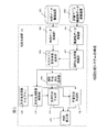
距離ベース構造物データを用いた地図生成について、高架橋データの生成を例に図2に示す。図2(a)は地図データ蓄積装置101から検索された地図データ201であり、このなかに高架橋を表すスケルトン図形202が記載されている。図2(b)はスケルトン図形202に沿って平面形状データ203〜211を生成した例である。ここで図形203、204、205は高架橋を表す図形であり、図形204、204、207、208、210、211は壁を表す図形である。図2(c)は平面地図201の視点を変更して斜め視地図212に変換し、スケルトン図形202に沿って立体形状により高架橋データを生成した例である。図2(c)では壁データ213〜218が生成されている.図2(b)における壁データの対応は,204→213、205→214、207→215、208→216、210→217、211→218である。また橋脚データ219が表示されている。橋脚データは立体表示によりはじめて生成される図形である。
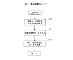
図2に示すような地図データを距離ベース構造物データを用いて生成するステップを図3に示す。また、構造物データと地図データとの関係を図4に示す。
ステップ1:地図データの検索(ステップ301)
地図データ検索部104は地図データ蓄積装置101より、図4に示すような地図データ401を検索する。この中には構造物の図形データを生成するためのガイドとなるスケルトン図形402が含まれている。
ステップ2:距離ベース構造物データの検索(ステップ302)
距離ベース構造物データ検索部105は距離ベース構造物データ蓄積装置102より、図5に示すような距離ベース構造物データ413を検索する。
ステップ3:すべてのスケルトン図形についての実行済確認(ステップ303)
地図データ401に含まれるすべてのスケルトン図形について、ステップ304以降を実行したかどうかの確認を行う。未済であればスケルトン図形を検索しステップ304以降を実施する。実行済であれば処理を終了する。スケルトン図形の検索は、スケルトン検索・追跡部106で地図データの中から検索する。この検索は地図座標データ403のレイヤ(層)番号(LYN)404を参照し、スケルトン図形に対応する層番号持つ図形を選択することに対応する。
ステップ4:構造物データの選択(ステップ304)
スケルトン検索・追跡部106において、ステップ302で検索した構造物データの中から、スケルトン図形の図形番号(FGN)405に対応する構造物データ413を検索する(対応づけ435)。
ステップ5:地図上基点の生成(ステップ305)
図形生成情報検索部107ではステップ4(ステップ304)で検索された構造物データに格納されている基点座標(BCO)415を検索し,スケルトン図形402上の点407に配置する(対応づけ436)。この基点座標はかならずしもスケルトン図形の座標に対応していない。また地図の精度が不十分のためスケルトン図形上にない場合もある。このときはスケルトン図形を構成する最寄りの線分に基点座標から垂線を下ろし、新しい基点座標とする。
ステップ6:すべての構造物データに対して実効済かどうかの確認(ステップ306)
距離ベース構造物データ409に記載されたすべての基点座標について実行済であることを確認する。未済であればステップ307以降を実施し、実行済であればステップ303を実行する。
ステップ7:図形生成範囲の検索(ステップ307)
スケルトン検索・追跡部106では、基点から開始点までの距離(DIST_S)416と終了点までの距離(DIST_E)417に相当する場所まで基点からスケルトン図形402の追跡を行い、地図上の開始点と終了点の位置を特定し図形生成範囲406を特定する。このときの開始点Ps 1408と終了点Pe 1409の座標は、図形生成開始/終了点管理データ425に格納する(対応づけ438)。開始点はSCO 426,終了点はECO 427であり、Ps 1の座標は(Xs1, Ys1, Zs1)428、Pe 1の座標は(Xe1, Ye1, Ze1)429である。
ステップ8:形状生成関数の検索(ステップ308)
形状生成関数検索部110では、形状生成関数ライブラリ109から構造物図形を生成する関数を選択する。形状生成関数ライブラリ430は、関数番号FUNC_N431と対応付けられた形状生成関数スクリプト(FUNCTION)432が格納されており、構造物データ413に格納された図形生成番号(FUNC_N)418と同一の番号433に対応する形状生成関数434を選択する(対応づけ437)。
ステップ9:図形次元の選択(ステップ309)
表示する次元の選択を行う。これは形状生成関数434のスクリプトによって表示次元が決まる。形状生成関数スクリプト434は関数名に「3D」と記載されており立体表現になることを示す。表示次元が立体の場合は、ステップ310以降を実行し、2次元(平面)の場合はステップ314以降を実行する。
ステップ10:立体形状データの生成(ステップ310)
立体形状生成部111では、構造物データ413に記載された形状生成パラメータに従って立体の高架橋データを生成する。図4では、高架幅ELW420、高架高さELH421、壁厚さWLW423、壁高さWLH424を形状生成パラメータとして形状生成関数434に引数として入力する。このとき生成した構造物図形データは地図座標データ403の形式で表されるが、図形番号(FGN)405は、立体高架図形、立体壁図形についてそれぞれ高架図形番号(FNE)419、壁図形番号(FNW)422の値を格納する。また層番号(LYN)は生成した図形であることを示す番号とする。
ステップ11:交差部の整形(ステップ311)
ステップ310において生成した形状は、スケルトン図形の折れ曲がり位置において図形がオーバーラップすることがある。そのため、立体形状生成部111では、交差部のオーバーラップを計算し整形を行う。
ステップ12:立体地図データの格納(ステップ312)
ステップ311で生成した構造物図形データを地図データ蓄積装置101に格納する。
ステップ13:立体地図データの表示(ステップ313)
地図表示部113は、ステップ311で生成した図形データを表示する。これは図2(c)に示す表示イメージとなる。図5において形状生成関数434から構造物図形データ(高架図形データ410、壁図形データ411、412)が生成されている(対応づけ439)。
ステップ14:平面形状データの生成(ステップ314)
平面形状生成部112では、構造物データ413に記載された形状生成パラメータに従って平面の高架橋データを生成する。ここでは高架幅ELW416、壁厚さWLW423を形状生成パラメータとして形状生成関数にパラメータとして入力する。このとき生成した構造物図形データは地図座標データ403の形式(Z座標は0を入れておく)で表されるが、図形番号(FGN)405は、平面高架図形、平面壁図形についてそれぞれ高架図形番号(FNE)419、壁図形番号(FNW)422の値を格納する。また層番号(LYN)は生成した図形であることを示す番号とする。
ステップ15:平面図形交差部の整形(ステップ315)
ステップ314において生成した形状はスケルトン図形の折れ曲がり部において図形がオーバーラップすることがある。そのため、平面形状生成部112では、交差部のオーバーラップを計算し整形を行う。
ステップ16:平面地図データの格納(ステップ316)
ステップ314で生成した構造物図形データを地図データ蓄積装置101に格納する。
ステップ17:平面地図データの表示(ステップ317)
地図表示部113は、ステップ314で生成した図形データを表示する。これは図2(b)に示す表示イメージとなる。
以上のように図3に示す地図生成ステップを利用することによって、地図データを生成することができるが、さらに構造物データと矛盾しない地図の更新にも利用することができる。例えば、更新内容として、立体データの長さや立体データの高さが考えられる。このような場合、地図図形の変更を伴う。そのため次のような更新ステップを実行する。
ステップ1:距離ベース構造物データの数値変更(ステップ401)
構造物データ検索部105より距離ベース構造物データを検索し、形状パラメータに対応するデータ項目の値を変更する。
ステップ2:地図データの消去(ステップ402)
更新の対象となったスケルトン図形を検索し、このスケルトン図形に対応して生成した地図データを消去する。これは構造物データ413に格納された図形番号(FNE419またはFNW422)に対応する図形データを地図座標データ403から検索してデータを消去することに相当する。
ステップ3:地図データの生成(ステップ403)
図3に示す地図データの生成ステップを、スケルトン図形に対して実行する。
このように、構造物データと地図データとの連携により、構造物データの変更が地図の変更につながるため、両方を更新する場合と比較して更新に要するコストが低減されるとともに、地図データは古いデータは消去されて新しいデータが生成されるため、構造物データと地図データとの矛盾を回避することができる。
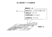
以上に示すような方式で地図図形を生成すると、生成した図形を選択することによって、構造物の図形生成に使われるパラメータ以外の関連する属性を検索することもできる。いま、図形生成関連以外の構造物データが413に追加格納されているとする。地図座標データ403の形式で図形を生成した場合に、構造物データ413に格納された、高架図形番号(FNE)419と壁図形番号(FNW)422を図形番号(FGN)405に格納されているため、図形を選択した場合、この図形番号(FGN)と一致する構造物データ413の図形番号(FGN)414を検索し、表示する構造物データを検索して表示することになる。図6に属性を検索した結果を示す。ここでは壁図形を表す図形601を選択し、関連する属性データ602を検索して表示した結果である。
図2および図6は実際にユーザに見える表示インタフェースを表す。図2では平面地図(図2(a))から構造物データを生成した地図(図2(b))を生成表示し、さらに必要によって立体地図(図2(c))を生成する。また、ここから図7に示すように立体形状図形を指示することにより構造物データの検索を行う。又、指示入力手段を介して構造物データを更新する指示を入力した場合には、更新された情報に基づいた構造物を生成して表示しなおすことができる。
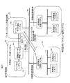
以上に示した、地図作成方式は専用ハードウエアだけでなく計算機ソフトウエアによっても実現される。とくに道路や鉄道のような長距離に及ぶ施設管理においては、決められた区間ごとに管理者が存在する。そして地図作成ソフトウエアの利用者は多数存在するため、地図作成ソフトウエアを利用者毎にインストールするのではなく、必要とするときにダウンロードする方法が有効である。これにより新しい施設の地図形状生成に対応してソフトウエアのバージョンが上がった場合、すべての利用者にバージョンアップソフトウエアの提供が容易となる。また、地図/構造物データについても各区間毎の施設管理者が隣接する区間の施設の地図/構造物データを参照することもあるため、地図/構造物データをネットワークを利用してダウンロードする。図7に示すような運用システムによってデータやプログラムを供給する。図7の運用システムは、次の3個の組織によって構成される。
プログラム提供組織701
地図生成ソフトウエアと地図/構造物データを保管管理している組織である。ここには提供する地図生成ソフトウエアと地図/構造物データを管理するデータ・ソフトウエア提供システム706が配置される。
区間施設管理組織702
実際に地図生成ソフトウエアを使用する組織である。ここには、区間管理組織で使用する各区間に対応する地図/構造物データと、地図生成ソフトウエアの利用を管理する区間施設管理システム707、実際に地図/構造物データと地図生成ソフトウエアを使用する利用端末システム708により構成される。
中央管理組織703
区間施設管理組織702で生成または更新した地図/構造物データを参照する組織である。ここでは、全区間における地図/構造物データを収集して格納する全施設データ保管システム709とデータを参照するためのデータ表示システム710より構成される。
これらの組織はネットワーク704と705によって接続されている。ネットワーク704は組織全体を接続する。またネットワーク705は区間施設管理組織702の中にのみ利用可能である。これらのネットワークはインタネットに基づくイントラネットであってもよい。次に地図/構造物データ運用の仕組みを示す。
地図/構造物データおよび地図生成ソフトウエアはあらかじめデータ・プログラム提供組織701にて管理されている。まず、区間施設管理組織702の利用端末システム708が、区間施設管理システム707に対して地図/構造物データおよび地図生成ソフトウエアの仕様を申告する。区間施設管理システム707は各利用端末システム708からの要求をまとめて、データ・ソフトウエア提供システム706に対して送付する。そしてデータ・ソフトウエア提供システム706ではその要求に従って、区間ごとの地図/構造物データおよび地図生成ソフトウエアを区間施設管理システム707にネットワークを通して配布する。また、隣接する区間のデータを要求された場合も対応する。いったん区間施設管理システム707に要求された地図/構造物データと地図生成ソフトウエアは格納され、利用端末システム708が区間施設管理システム707にアクセスして地図/構造物データおよび地図生成ソフトウエアをダウンロードして使用する。このようなシステムでは、データやソフトウエアの利用者が区間毎にグループ化され、グループごとにデータやソフトウエアを管理する区間施設管理システム707にアクセスを行うため、データ・ソフトウエア提供システムから直接ダウンロードしなくてもよくデータやソフトウエア利用準備に要する時間が短縮できる。
区間施設管理組織702での利用によって変更された地図/構造物データは、データ・プログラム提供組織701に送られる。また、全体管理組織703において現状の地図/構造物データを参照する場合には、データ・ソフトウエア提供システム706に対して最新のデータを要求する。データ・ソフトウエア提供システム706は最新の地図/構造物データを前施設データ保管システム709に送付する。全体管理組織703では地図/構造物データの維持管理や、地図生成のような実作業は行わない。全施設データ保管システム709に格納された地図/構造物データをデータ表示システム710を用いて参照する。
データ・ソフトウエア提供組織は地図生成ソフトウエアの使用回数によって区間施設管理組織702に対して課金する。また、地図/構造物データの著作権を保有する場合は、地図/構造物データの提供を課金する。課金の関係は次のような、方法が考えられる。
利用端末システムごとの使用ライセンス方式
データ・プログラム提供組織701は利用端末システム708ごとに固有の番号(ID)を付けて利用端末システムごとの利用によって課金する。区間施設管理システム707では、利用端末からの要求に基づいてそのIDをデータ・プログラム提供組織701に送付する。そしてデータ・ソフトウエア提供システム706で、端末ごとの使用の可否の判断及び課金して、ソフトウエアを区間施設管理システム707に送る。
区間施設管理組織ごとの使用ライセンス方式
期間契約によってデータ・ソフトウエア提供組織701と区間施設管理組織702との間で地図生成ソフトウエアの使用を許可する。
以上は地図生成ソフトウエアのライセンス契約であるが、地図データや属性データの権利をデータ・ソフトウエア提供組織701が保有している場合は上記のライセンス契約を地図/構造物データの使用に対しても行う。
以上のように本願では、
構造物の概略図形を有する地図データと、基点座標と該基点から構成物図形の開始点と終了点までの距離とを対応づけた構造物管理データを記録する記録手段に接続され、
上記基点に対応する位置を上記地図データから検索する手段と、
上記構造物図形を生成する範囲を上記概略図形のデータを用いて決定する手段と、
上記生成区間に上記構造物管理データに格納された構造物パラメータを利用して構造物形状生成プログラムによって構造物図形生成する手段と、
該生成した構造物図形を表示させる手段とを有することを特徴とする地図生成システム。
さらに、地図を検索する地図データ検索部と、距離ベース構造物データを検索する距離ベース構造物データ検索部と、距離ベース構造物DBから距離関連情報を検索する距離情報検索部と地図に記載されたスケルトン図形データの追跡を行い図形生成範囲を決定するスケルトン図形追跡部と、構造物図形の生成範囲をスケルトン図形を追跡することによって距離に対応付けられた構造物パラメータを検索する構造物パラメータ検索部、構造物形状生成プログラムからなる形状生成関数ライブラリ、形状生成関数を選択する形状生成関数検索部、構造物生成範囲に平面図形による構造物図形を生成する平面図形形状生成部、構造物生成範囲に立体図形による構造物図形を生成する立体図形形状生成部、生成した地図図形を表示する地図表示部より構成し、地図データ検索部で検索した地図データに記載されたスケルトン図形データを、距離ベース構造物データ検索部によって検索された構造物データに記載されている構造物までの距離情報に基づいて構造物図形生成範囲を検索するスケルトン図形検索部により構造物図形生成範囲を決定し、構造物パラメータ検索部によって構造物データから検索された構造物パラメータを用いて、平面図形形状生成部、立体図形形状生成部によって構造物図形を、形状生成関数検索部によって検索した形状生成関数によって生成し、地図表示部によって表示することを特徴とする地図生成システムを開示した。
【0006】
【発明の効果】
距離ベース構造物データに記述した数値情報を用いて地図を生成することにより、地図データの入力に要するコストを低減することができる。また、距離ベース構造物データの更新によって地図データを再度計算生成することにより、構造物データと地図データの両方を人手で変更を行う場合と比較して、地図の更新に要するコストが低減できるとともに、距離ベース構造物データと地図データとの矛盾を回避することもできる。
【図面の簡単な説明】
【図1】距離ベース構造物データを利用した地図生成システムの構成を示す図である。
【図2】地図生成の表示例を示す図である。
【図3】地図生成のフローを示す図である。
【図4】距離ベース構造物データから地図を作成するためのデータ関連を示す図である
【図5】地図更新のフローを示す図である。
【図6】生成した地図から属性を検索した例を示す図である。
【図7】地図生成ソフトウエアを運用する方法である。
【符号の説明】
101……地図データ蓄積装置、102……距離ベース構造物データ蓄積装置、103……地図生成部、104……地図データ検索部、105……構造物データ検索部、106……スケルトン図形検索・追跡部、107……図形生成情報検索部、108……図形次元選択部、109……形状生成関数ライブラリ、110……形状生成関数検索部、111……立体形状生成部、112……平面形状生成部、113……地図表示部、401……地図データ、402……スケルトン図形、403……地図座標データ、404……層番号(LYN)、405……図形番号(FGN)、406……距離ベース構造物データ、406……図形生成範囲、407……基点座標、408……図形生成開始点、409……図形生成終了点、410……高架データ、411……壁データ、412……壁データ、413……距離ベース構造物データ、414……図形番号(FGN)、415……基点座標(BCO)、416……基点から図形生成開始点までの距離(DIST_S)、417……基点から図形生成終了点までの距離(DIST_E)、418……形状生成関数番号(FUNC_N)、419……高架図形番号(FNE)420……高架幅(ELW)、421……高架高さ(ELH)、422……壁図形番号(FNW)、423……壁厚さ(WLW)、424……壁高さ(WLH)、425……図形生成開始/終了点管理データ、426……地図上開始点座標(SCO)、427……地図上終了点座標(ECO)、428……地図上開始点座標値、429……地図上終了点座標値、430……形状生成関数ライブラリ、431……形状生成関数番号(FUNC_N)、432……形状関数(FUNCTION)、433……形状生成関数番号値、434……形状生成関数スクリプト
435……地図データと構造物データの対応づけ、436……構造物データの基準点座標と地図上の基点との対応づけ、437……構造物データと形状生成関数ライブラリの対応づけ、438……地図上の開始点/終了点と図形生成開始点/終了点管理データとの対応づけ、439……形状生成関数ライブラリと地図データとの対応づけ。[0001]
TECHNICAL FIELD OF THE INVENTION
The present invention provides a geographic information system (GIS:GeographicInformationSand a system for generating a structure graphic on a map using the structure parameters stored in the distance-based structure management data managed by associating the distance from the base point with the structure data.
[0002]
[Prior art]
Information on structures related to railway facilities, road facilities, river facilities, etc. is managed as data (also using the name of kilometer data) corresponding to the distance from a predetermined base point to the structure. I have. Concretely, the information on the structure can be the construction date, management number, structure, etc. These information correspond to the distance from the predetermined base point to the start and end points of the facility. Attached and managed.
[0003]
[Problems to be solved by the invention]
When the above-described structure information is stored in the database, the search for the information is performed using the name and the distance of the structure as a search key. However, in this method, the distance to the structure is known, but the position is not known. In order to confirm the position, it is necessary to separately refer to a drawing such as a map. Therefore, in order to confirm the position of the structure and its contents, it is necessary to refer not only to the database that stores the structure data but also to the map. This makes it difficult to specify the location when the structure is damaged or the like. Furthermore, even if the structure data and the map data are computer data, they are not associated with each other. Therefore, there is no guarantee that updating of one will surely lead to updating of the other. For this reason, if only one update is performed and the other is left as it is, inconsistency may occur between data. In such a case, the reliability of the map data and the structure data is reduced. Therefore, it is necessary to reliably link the structure data and the map data so that the position of the structure can be confirmed on the map, and to update the structure data and the map data without inconsistency. .
[0004]
[Means for Solving the Problems]
In order to solve the above-described problem, graphic data to be superimposed on a map is generated from numerical data corresponding to a structure parameter stored in the distance-based structure data by associating the distance-based structure data with map data. Therefore, in the map data, only a skeleton figure for generating a shape is created, and the skeleton is based on the distance from the base point to the start point and the distance from the base point to the end point stored in the distance-based structure data. Means for tracking a figure and specifying a figure generation range, means for selecting a shape generation function of a figure to be generated from a shape generation function library, and extracting structure parameters necessary for shape generation from distance-based structure data, The problem can be solved by introducing a shape generation unit that generates a structure shape by inputting the selected shape generation function into the selected shape generation function, thereby generating structure data based on figures from the distance-based structure data.
[0005]
BEST MODE FOR CARRYING OUT THE INVENTION
In order to solve the above problems, the invention of the present application associates structure data with map data by introducing a map generation that generates graphic data from numerical data that is structure data and superimposes the data on a map. Specifically, in the map data, only a schematic figure (hereinafter, referred to as a skeleton figure) serving as a guide for generating a shape using the structure data is created, and a base point stored in the structure data is created. Using the coordinates and the distances to the start point and the end point, the skeleton figure is tracked based on each distance to specify the shape generation range. Then, a shape generation function for generating a structure figure is selected from the shape generation function library, and the structure data is input to the selected shape generation function, thereby generating a structure shape and generating structure data based on the figure shape. . The components of such a map generation system are as follows.
(1) Map
A data storage medium for storing map data composed of a skeleton graphic composed of a coordinate sequence and a vector graphic representing other features. For example, it corresponds to a hard disk.
(2) Distance-based structure
Information of a structure is recorded in association with a distance from a predetermined base point to a start point and an end point of the structure, and managed distance-based structure data (hereinafter, referred to as structure data) is stored. Data storage medium. As the information on the structure, specifically, the number of the corresponding skeleton figure as the information on the structure, the distance from the base point to the figure generation start point, the distance from the base point to the figure generation end point, the shape generation function number, the elevated figure Not only the number, elevated width, elevated height, wall figure number, wall thickness, wall height, but also the construction date, structural content, and the like can be considered. For example, it corresponds to a hard disk.
(3) Map generator 103
This is a function of generating map data from structure data, and is configured by
(4) Map
A function of searching and reading map data from the map
(5) Structure
A function of retrieving and reading structure data from the distance-based structure
(6) Skeleton figure search / tracking unit 106
A guide figure (skeleton figure) for generating figure data is searched from the map data, and a skeleton figure is calculated from base point coordinates and distance data to the start point and end point, which are items of the structure data. A function to track and determine the scope of figure generation.
(7) Graphic generation information search unit 107
A function of searching the structure data searched by the structure
(8) Graphic generation dimension selection unit 108
A function to determine whether to generate a shape in three dimensions or a planar figure.
(9) Shape
A program library that stores a shape generation function program that generates a structure figure using data items of structure data as parameters.
(10) Shape generation
A function of retrieving a shape generation function program from the shape generation function library 108.
(11) Three-dimensional shape generation unit 111
A function that generates a three-dimensional figure according to the shape generation function and shapes it at the intersection of the figures.
(12) 3D
A function to generate a plane figure according to the shape generation function and to shape it at the intersection of the figures.
(13)
Function to display generated map data
Regarding map generation using distance-based structure data, FIG. 2 illustrates generation of viaduct data as an example. FIG. 2A shows
FIG. 3 shows steps for generating map data as shown in FIG. 2 using the distance-based structure data. FIG. 4 shows the relationship between the structure data and the map data.
Step 1: Search for map data (Step 301)
The map
Step 2: Search for distance-based structure data (Step 302)
The distance-based structure
Step 3: Confirmation of execution for all skeleton figures (Step 303)
For all skeleton figures included in the
Step 4: Select structure data (Step 304)
The skeleton search / tracking unit 106 searches the structure data retrieved in step 302 for
Step 5: Generating a base point on the map (Step 305)
The graphic generation information retrieval unit 107 retrieves the base point coordinates (BCO) 415 stored in the structure data retrieved in step 4 (step 304) and arranges them at a
Step 6: Check whether all structure data has been executed (Step 306)
It is confirmed that the execution has been completed for all the base point coordinates described in the distance-based structure data 409. If not completed, step 307 and subsequent steps are performed, and if completed, step 303 is performed.
Step 7: Search for figure generation range (step 307)
The skeleton search / tracking unit 106 tracks the skeleton figure 402 from the base point to a location corresponding to the distance (DIST_S) 416 from the base point to the start point and the distance (DIST_E) 417 from the end point to the start point on the map. The position of the end point is specified, and the
Step 8: Search for a shape generation function (Step 308)
The shape generation
Step 9: Selection of figure dimensions (Step 309)
Select the dimensions to be displayed. The display dimension is determined by the script of the
Step 10: generation of three-dimensional shape data (step 310)
The three-dimensional shape generation unit 111 generates three-dimensional viaduct data in accordance with the shape generation parameters described in the
Step 11: Shaping the intersection (Step 311)
In the shape generated in step 310, the figures may overlap at the bending position of the skeleton figure. Therefore, the three-dimensional shape generation unit 111 calculates and shapes the overlap of the intersection.
Step 12: storage of three-dimensional map data (step 312)
The structure graphic data generated in step 311 is stored in the map
Step 13: Display of 3D map data (Step 313)
The
Step 14: Generation of planar shape data (Step 314)
The plane
Step 15: Shaping the intersection of the plane figure (Step 315)
In the shape generated in
Step 16: storing plane map data (step 316)
The structure graphic data generated in
Step 17: Display of planar map data (Step 317)
The
As described above, the map data can be generated by using the map generation step shown in FIG. 3, but can also be used for updating a map that does not contradict the structure data. For example, the length of three-dimensional data and the height of three-dimensional data can be considered as the update content. In such a case, there is a change in the map figure. Therefore, the following update steps are performed.
Step 1: Numerical change of distance-based structure data (Step 401)
The structure
Step 2: Deletion of map data (Step 402)
The skeleton figure to be updated is searched, and the map data generated corresponding to the skeleton figure is deleted. This corresponds to searching graphic data corresponding to the graphic number (FNE419 or FNW422) stored in the
Step 3: Generating map data (Step 403)
The map data generation step shown in FIG. 3 is executed for the skeleton figure.
As described above, since the link between the structure data and the map data causes a change in the structure data to lead to a change in the map, the cost required for the update is reduced as compared with the case where both are updated, and the map data is Since old data is deleted and new data is generated, inconsistency between structure data and map data can be avoided.
When a map graphic is generated by the method described above, related attributes other than the parameters used for generating the graphic of the structure can be searched by selecting the generated graphic. Now, it is assumed that structure data other than those related to graphic generation is additionally stored in 413. When a figure is generated in the form of the map coordinate
2 and 6 show the display interface that is actually visible to the user. In FIG. 2, a map (FIG. 2 (b)) in which structure data is generated from a plan map (FIG. 2 (a)) is generated and displayed, and a three-dimensional map (FIG. 2 (c)) is generated if necessary. Further, from here, the structure data is searched by designating a three-dimensional figure as shown in FIG. In addition, when an instruction to update the structure data is input through the instruction input unit, the structure can be generated and displayed based on the updated information.
The map creation method described above is realized not only by dedicated hardware but also by computer software. In particular, in managing facilities over long distances such as roads and railroads, there is a manager for each determined section. Since there are many users of the map creation software, it is effective to download the map creation software when needed instead of installing the software for each user. As a result, when the version of the software is increased in response to the generation of the map shape of a new facility, it becomes easy to provide the upgraded software to all users. Also, regarding the map / structure data, since the facility manager of each section may refer to the map / structure data of the facility in the adjacent section, the map / structure data is downloaded using the network. Data and programs are supplied by an operation system as shown in FIG. The operation system of FIG. 7 is configured by the following three organizations.
An organization that stores and manages map generation software and map / structure data. Here, a map generation software to be provided and a data / software providing system 706 for managing map / structure data are arranged.
Section
The organization that actually uses the map generation software. Here, the map / structure data corresponding to each section used by the section management organization, the section
The section refers to the map / structure data generated or updated by the section
These organizations are connected by
The map / structure data and the map generation software are managed in advance by the data /
The map / structure data changed by the use by the section
The data software providing organization charges the section
License system used for each terminal system
The data /
Use license method for each section facility management organization
The term contract permits the use of the map generation software between the data
The above is the license agreement for the map generation software. If the data /
As described above, in the present application,
Map data having a schematic figure of a structure, and a recording means for recording structure management data in which base point coordinates and distances from the base point to the start point and the end point of the constituent figure are connected;
Means for searching the map data for a position corresponding to the base point;
Means for determining a range in which the structural figure is generated using data of the schematic figure;
Means for generating a structure graphic by a structure shape generation program using a structure parameter stored in the structure management data in the generation section;
Means for displaying the generated structure graphic.
Further, a map data search unit for searching a map, a distance-based structure data search unit for searching distance-based structure data, a distance information search unit for searching distance-related information from the distance-based structure DB, and a map are described in the map. Skeleton figure tracking unit that tracks the skeleton figure data that has been set and determines the figure generation range, and structure parameter search that searches the skeleton figure for the generation range of the structure figure and searches for the structure parameter associated with the distance Section, a shape generation function library including a structure shape generation program, a shape generation function search section for selecting a shape generation function, a plane figure shape generation section for generating a structure figure by a plane figure in a structure generation range, a structure generation range The three-dimensional figure shape generation part that generates the structure figure by the three-dimensional figure, the map display part that displays the generated map figure The skeleton graphic data described in the map data retrieved by the map data retrieval unit is structured based on the distance information to the structure described in the structure data retrieved by the distance-based structure data retrieval unit. The skeleton figure search unit that searches the object figure generation range determines the structure figure generation range, and the structure parameter search unit uses the structure parameters retrieved from the structure data to generate a plane figure shape generation unit and three-dimensional figure shape A map generation system has been disclosed in which a structure graphic is generated by a generation unit using a shape generation function searched by a shape generation function search unit and displayed by a map display unit.
[0006]
【The invention's effect】
By generating a map using the numerical information described in the distance-based structure data, the cost required for inputting the map data can be reduced. Also, by regenerating the map data by updating the distance-based structure data, the cost required for updating the map can be reduced as compared with a case where both the structure data and the map data are changed manually. Also, inconsistency between the distance-based structure data and the map data can be avoided.
[Brief description of the drawings]
FIG. 1 is a diagram showing a configuration of a map generation system using distance-based structure data.
FIG. 2 is a diagram showing a display example of map generation.
FIG. 3 is a diagram showing a flow of map generation.
FIG. 4 is a diagram showing data relations for creating a map from distance-based structure data.
FIG. 5 is a diagram showing a flow of map updating.
FIG. 6 is a diagram showing an example of searching for an attribute from a generated map.
FIG. 7 shows a method for operating map generation software.
[Explanation of symbols]
101: Map data storage device, 102: Distance-based structure data storage device, 103: Map generation unit, 104: Map data search unit, 105: Structure data search unit, 106: Skeleton figure search / Tracking unit 107... Figure generation information search unit 108... Figure
435... Correlation between map data and
Claims (9)
上記基点に対応する位置を上記地図データから検索する手段と、
上記構造物図形を生成する範囲を上記概略図形のデータを用いて決定する手段と、
上記生成区間に上記構造物管理データに格納された構造物パラメータを利用して構造物図形生成する手段と、
該生成した構造物図形を表示させる手段とを有することを特徴とする地図生成システム。Map data having a schematic figure of a structure, and a recording means for recording structure management data in which base point coordinates and distances from the base point to the start point and the end point of the constituent figure are connected;
Means for searching the map data for a position corresponding to the base point;
Means for determining a range in which the structural figure is generated using data of the schematic figure;
Means for generating a structure graphic using the structure parameters stored in the structure management data in the generation section,
Means for displaying the generated structure graphic.
上記指示入力手段から受けた指示情報を上記構造物管理情報から検索する手段とを更に有し、
該検索された構造物管理情報の管理する構造物を含む上記地図データを表示させることを特徴とする請求項1乃至2に記載の地図生成システム。Instruction input means;
Means for retrieving the instruction information received from the instruction input means from the structure management information,
3. The map generation system according to claim 1, wherein the map data including the structure managed by the searched structure management information is displayed.
上記指示入力手段を介して上記構造物管理情報の更新指示を受けた際に、更新された上記構造物管理情報に基づいて、該構造物管理情報の管理する構成物を再生成する手段とをさらに有することを特徴とする請求項1乃至3の何れかに記載の地図生成システム。Instruction input means;
Means for regenerating a component managed by the structure management information based on the updated structure management information when receiving an update instruction of the structure management information via the instruction input means. The map generation system according to any one of claims 1 to 3, further comprising:
少なくとも1の構造物を表示した上記地図データを表示手段に表示させる手段と、
基点からの上記構造物の開始点及び終了点までの距離情報と該構造物の属性情報とを表示させる手段と、
上記表示した距離情報若しくは属性情報の少なくとも何れかについての変更入力を受ける手段と、
上記変更入力に基づいた構造物を上記地図データに生成して上記表示手段に再表示させる手段とを有することを特徴とする地図生成システム。Recording means for recording map data and structure management information of structures in the map;
Means for displaying on the display means the map data showing at least one structure;
Means for displaying distance information from the base point to the start point and end point of the structure and attribute information of the structure,
Means for receiving a change input for at least one of the displayed distance information or attribute information,
Means for generating a structure based on the change input on the map data and redisplaying the structure on the display means.
上記表示手段は、上記表示された構造物が上記表示手段で指示されると、該構造物の構造物データも表示することを特徴とする請求項4記載の地図生成システム。Further comprising instruction means,
5. The map generation system according to claim 4, wherein when the displayed structure is designated by the display device, the display unit also displays the structure data of the structure.
上記サーバは、
プログラムと上記複数のコンピュータの識別番号を記録する手段と、
上記コンピュータからのアクセス要求の可否を判断する手段とを有し、
上記プログラムは、上記基点に対応する位置を上記地図データから検索するステップと、上記構造物管理データに基づいて設定される上記地図データ上の領域に上記構造物を生成するステップとを上記コンピュータに実行させるものであることを特徴とする地図管理システム。A map data having a schematic figure of a structure, a server that records structure management data in which base coordinates and a distance from the base to the start point and the end point of the constituent figure are recorded, and a plurality of computers,
The above server,
Means for recording a program and identification numbers of the plurality of computers,
Means for judging whether or not an access request is received from the computer,
The program includes a step of searching the map data for a position corresponding to the base point, and a step of generating the structure in an area on the map data set based on the structure management data. A map management system characterized by being executed.
Priority Applications (3)
| Application Number | Priority Date | Filing Date | Title |
|---|---|---|---|
| JP2002326259A JP2004163480A (en) | 2002-11-11 | 2002-11-11 | Map preparation system and map management system |
| KR1020030078974A KR20040041512A (en) | 2002-11-11 | 2003-11-10 | Map generating system and map management system |
| US10/703,420 US7107150B2 (en) | 2002-11-11 | 2003-11-10 | Map generating system and map management system |
Applications Claiming Priority (1)
| Application Number | Priority Date | Filing Date | Title |
|---|---|---|---|
| JP2002326259A JP2004163480A (en) | 2002-11-11 | 2002-11-11 | Map preparation system and map management system |
Publications (2)
| Publication Number | Publication Date |
|---|---|
| JP2004163480A true JP2004163480A (en) | 2004-06-10 |
| JP2004163480A5 JP2004163480A5 (en) | 2005-10-20 |
Family
ID=32462551
Family Applications (1)
| Application Number | Title | Priority Date | Filing Date |
|---|---|---|---|
| JP2002326259A Pending JP2004163480A (en) | 2002-11-11 | 2002-11-11 | Map preparation system and map management system |
Country Status (3)
| Country | Link |
|---|---|
| US (1) | US7107150B2 (en) |
| JP (1) | JP2004163480A (en) |
| KR (1) | KR20040041512A (en) |
Cited By (3)
| Publication number | Priority date | Publication date | Assignee | Title |
|---|---|---|---|---|
| CN105303637A (en) * | 2015-11-03 | 2016-02-03 | 用友网络科技股份有限公司 | Coordinate point uploading and automatic routing inspection device and method based on mobile application |
| WO2019102968A1 (en) * | 2017-11-22 | 2019-05-31 | 三菱電機株式会社 | Map collecting system, map server device, vehicle-mounted device, and map collecting method |
| JP2019139680A (en) * | 2018-02-15 | 2019-08-22 | 株式会社デンソー | Virtual environment creation device |
Families Citing this family (21)
| Publication number | Priority date | Publication date | Assignee | Title |
|---|---|---|---|---|
| JP4319857B2 (en) * | 2003-05-19 | 2009-08-26 | 株式会社日立製作所 | How to create a map |
| JP2005069967A (en) * | 2003-08-27 | 2005-03-17 | Alpine Electronics Inc | Onboard navigation apparatus |
| US7822741B2 (en) * | 2004-06-21 | 2010-10-26 | Microsoft Corporation | API for programmatic retrieval and replay of database trace |
| JP5265077B2 (en) * | 2005-01-18 | 2013-08-14 | パイオニア株式会社 | Map distribution device, map acquisition device, map processing system, map distribution method, map acquisition method, map distribution program, map acquisition program, and recording medium |
| KR100634536B1 (en) * | 2005-01-25 | 2006-10-13 | 삼성전자주식회사 | 3 dimensional transformation method for 2 dimensional overpass data on 3 dimensional graphics environment and apparatus therefor, and 3 dimensional visualization method for 2 dimensional overpass data on 3 dimensional graphics environment and apparatus using the same |
| CN100392655C (en) * | 2006-01-17 | 2008-06-04 | 中国地质调查局发展研究中心 | National geologic maps data model system |
| US8484059B2 (en) * | 2006-10-17 | 2013-07-09 | At&T Intellectual Property I, L.P. | Methods, systems, and products for surveying facilities |
| US11482058B2 (en) | 2008-09-09 | 2022-10-25 | United Parcel Service Of America, Inc. | Systems and methods for utilizing telematics data to improve fleet management operations |
| US8416067B2 (en) | 2008-09-09 | 2013-04-09 | United Parcel Service Of America, Inc. | Systems and methods for utilizing telematics data to improve fleet management operations |
| US8838631B2 (en) * | 2008-09-25 | 2014-09-16 | Jr East Consultants Company | Facility management system using geographic information system |
| KR100967690B1 (en) * | 2010-03-10 | 2010-07-07 | 주식회사 삼원알텍 | Heating apparatus having water level sensing function |
| US9208626B2 (en) | 2011-03-31 | 2015-12-08 | United Parcel Service Of America, Inc. | Systems and methods for segmenting operational data |
| US9117190B2 (en) | 2011-03-31 | 2015-08-25 | United Parcel Service Of America, Inc. | Calculating speed and travel times with travel delays |
| US9953468B2 (en) | 2011-03-31 | 2018-04-24 | United Parcel Service Of America, Inc. | Segmenting operational data |
| US8996287B2 (en) | 2011-03-31 | 2015-03-31 | United Parcel Service Of America, Inc. | Calculating speed and travel times with travel delays |
| US9070100B2 (en) | 2011-03-31 | 2015-06-30 | United Parcel Service Of America, Inc. | Calculating speed and travel times with travel delays |
| US9129449B2 (en) | 2011-03-31 | 2015-09-08 | United Parcel Service Of America, Inc. | Calculating speed and travel times with travel delays |
| US9805521B1 (en) | 2013-12-03 | 2017-10-31 | United Parcel Service Of America, Inc. | Systems and methods for assessing turns made by a vehicle |
| CN104599324A (en) * | 2015-02-06 | 2015-05-06 | 浪潮集团有限公司 | Map data loading method and map data loading device based on GIS (geographic information system) platform |
| US20160334225A1 (en) | 2015-05-11 | 2016-11-17 | United Parcel Service Of America, Inc. | Determining street segment headings |
| CN113252034A (en) * | 2020-02-12 | 2021-08-13 | 华为技术有限公司 | Path planning method and related equipment |
Family Cites Families (6)
| Publication number | Priority date | Publication date | Assignee | Title |
|---|---|---|---|---|
| US6321158B1 (en) * | 1994-06-24 | 2001-11-20 | Delorme Publishing Company | Integrated routing/mapping information |
| US5802492A (en) * | 1994-06-24 | 1998-09-01 | Delorme Publishing Company, Inc. | Computer aided routing and positioning system |
| JP3322137B2 (en) * | 1996-08-29 | 2002-09-09 | 株式会社デンソー | Vehicle navigation device |
| US6163749A (en) * | 1998-06-05 | 2000-12-19 | Navigation Technologies Corp. | Method and system for scrolling a map display in a navigation application |
| AU2001245573A1 (en) * | 2000-03-10 | 2001-09-24 | Spectra Precision Inc. | Versatile transmitter and receiver for position measurement |
| JP3783525B2 (en) * | 2000-05-18 | 2006-06-07 | 株式会社デンソー | Average vehicle speed calculation device and recording medium |
-
2002
- 2002-11-11 JP JP2002326259A patent/JP2004163480A/en active Pending
-
2003
- 2003-11-10 US US10/703,420 patent/US7107150B2/en not_active Expired - Fee Related
- 2003-11-10 KR KR1020030078974A patent/KR20040041512A/en not_active Application Discontinuation
Cited By (5)
| Publication number | Priority date | Publication date | Assignee | Title |
|---|---|---|---|---|
| CN105303637A (en) * | 2015-11-03 | 2016-02-03 | 用友网络科技股份有限公司 | Coordinate point uploading and automatic routing inspection device and method based on mobile application |
| CN105303637B (en) * | 2015-11-03 | 2018-05-18 | 用友网络科技股份有限公司 | Coordinate points upload and automatic inspection device and method based on mobile application |
| WO2019102968A1 (en) * | 2017-11-22 | 2019-05-31 | 三菱電機株式会社 | Map collecting system, map server device, vehicle-mounted device, and map collecting method |
| JP6541924B1 (en) * | 2017-11-22 | 2019-07-10 | 三菱電機株式会社 | Map collection system, map server device, in-vehicle device, and map collection method |
| JP2019139680A (en) * | 2018-02-15 | 2019-08-22 | 株式会社デンソー | Virtual environment creation device |
Also Published As
| Publication number | Publication date |
|---|---|
| US7107150B2 (en) | 2006-09-12 |
| KR20040041512A (en) | 2004-05-17 |
| US20040111213A1 (en) | 2004-06-10 |
Similar Documents
| Publication | Publication Date | Title |
|---|---|---|
| JP2004163480A (en) | Map preparation system and map management system | |
| JP5143149B2 (en) | Map information distribution method and map information distribution apparatus | |
| US7930100B2 (en) | Computer readable medium storing a map data updating program and map data updating terminal | |
| US7406482B2 (en) | System and method for updating a geographic database using satellite imagery | |
| JP5189838B2 (en) | Map data distribution system, map data distribution method, and communication terminal | |
| CN102338638B (en) | Navigation equipment and its map data updating method | |
| CN103927374B (en) | A kind of Web GIS map layer creation method based on SharpMap | |
| CN104679864A (en) | Intelligent tracking method and intelligent tracking device for suspected target based on GIS (Geographic Information System) | |
| JP2012527008A (en) | Location-based data service apparatus and method | |
| KR100998472B1 (en) | Apparatus and Method for Managing of Land Information | |
| CN102788586A (en) | Method and system for incremental updating of navigation electronic map | |
| JP2002024702A (en) | System and method for information rating, and computer- readable recording medium having information rating program recorded therein | |
| Morris et al. | Digital trail libraries | |
| KR20120034383A (en) | Automatic map update system and method thereof | |
| TW200944758A (en) | Methods and systems for adjusting route planning results, and machine readable medium thereof | |
| JP3495641B2 (en) | Updated map information distribution system, updated map information distribution server system, updated map information distribution client system, method, and recording medium recording the method | |
| CN111581306B (en) | Driving track simulation method and device | |
| CN112597579A (en) | Engineering project digital delivery method and system based on BIM | |
| CN110455276A (en) | A kind of path personalization route planning method | |
| US20210224466A1 (en) | Methods and systems for geographic map generation and rendering and unique miles and routes navigation | |
| JP3621286B2 (en) | Road map vectorization method and apparatus | |
| KR20010113202A (en) | Method For Indication Of Advertisement by using position information In Electronic Map | |
| JP3302986B1 (en) | Information management system | |
| JP2001033269A (en) | Three-dimensional road guidance image presenting method, three-dimensional guidance image presenting device and recording medium having three-dimensional guidance image presentation program recorded thereon | |
| CN114090706A (en) | Map management method, map management device and computer-readable storage medium |
Legal Events
| Date | Code | Title | Description |
|---|---|---|---|
| A521 | Written amendment |
Free format text: JAPANESE INTERMEDIATE CODE: A523 Effective date: 20050624 |
|
| A621 | Written request for application examination |
Free format text: JAPANESE INTERMEDIATE CODE: A621 Effective date: 20050624 |
|
| RD02 | Notification of acceptance of power of attorney |
Free format text: JAPANESE INTERMEDIATE CODE: A7422 Effective date: 20060512 |
|
| RD04 | Notification of resignation of power of attorney |
Free format text: JAPANESE INTERMEDIATE CODE: A7424 Effective date: 20060512 |
|
| A131 | Notification of reasons for refusal |
Free format text: JAPANESE INTERMEDIATE CODE: A131 Effective date: 20080527 |
|
| A521 | Written amendment |
Free format text: JAPANESE INTERMEDIATE CODE: A523 Effective date: 20080723 |
|
| A02 | Decision of refusal |
Free format text: JAPANESE INTERMEDIATE CODE: A02 Effective date: 20090203 |