JP2004163211A - Method of filling gel into hollow fiber, hollow fiber filled with gel, and organism-related substance microarray using the same - Google Patents
Method of filling gel into hollow fiber, hollow fiber filled with gel, and organism-related substance microarray using the same Download PDFInfo
- Publication number
- JP2004163211A JP2004163211A JP2002328179A JP2002328179A JP2004163211A JP 2004163211 A JP2004163211 A JP 2004163211A JP 2002328179 A JP2002328179 A JP 2002328179A JP 2002328179 A JP2002328179 A JP 2002328179A JP 2004163211 A JP2004163211 A JP 2004163211A
- Authority
- JP
- Japan
- Prior art keywords
- gel
- hollow fiber
- fiber
- hollow
- solution
- Prior art date
- Legal status (The legal status is an assumption and is not a legal conclusion. Google has not performed a legal analysis and makes no representation as to the accuracy of the status listed.)
- Pending
Links
Images


Abstract
Description
【0001】
【発明の属する技術分野】
本発明は、毛細管、中空繊維等のキャピラリーへゲルを充填する方法、及びゲル充填中空繊維の製造方法に関する。ゲル充填中空繊維は、キャピラリーゲル電気泳動、DNAマイクロアレイ等に使用される。
【0002】
【従来の技術】
キャピラリーゲル電気泳動法は、糖鎖の分離解析、光学分割、遺伝子配列解析等に広く利用されている。近年においては、ヒトゲノムプロジェクトの本格化により、ゲノム解析分野で広範囲に利用されており、例えば遺伝子発現解析、SNPs等の多型解析、プロテオーム解析等に利用されている。
【0003】
遺伝子発現解析の一例としては、予め有用な遺伝子由来のDNA断片等のプローブを、ゲルに固定化したゲル充填キャピラリーを準備し、検体をキャピラリー内へ導入して、プローブとの相互作用を観察する試みがなされている(特開平3−47097号公報参照)。
【0004】
さらにゲル充填キャピラリーは、DNAマイクロアレイの構成部材としても使用されている。このマイクロアレイは、整然配列した複数本のゲル充填キャピラリーを含むブロック体をキャピラリーの長手方向と交叉する方向で切断することにより得られる。このマイクロアレイは、各キャピラリーにより区画化され、該区画にゲルが保持されている。キャプチャープローブはゲルに保持されている。
【0005】
上記いずれの場合もキャピラリーにゲルを充填する必要があるが、ゲルを充填する方法としては、加圧してゲル溶液をキャピラー内に押し込む方法(加圧法:例えば特開平2−128158号、特開平5−196603号)、ゲル溶液を吸引してキャピラリー内に吸い上げる方法(減圧法:例えば特開2000−321244号)、減圧と加圧を併用する方法(例えば特開平3−31752号)に大別される。
【0006】
【特許文献1】
特開平2−128158号公報
【特許文献2】
特開平5−196603号公報
【特許文献3】
特開2000−321244号公報
【特許文献4】
特開平3−31752号公報
【0007】
【発明が解決しようとする課題】
キャピラリーのような細孔管に溶液を充填するには、精密な液量制御が必要となるが、上記のいずれの公報も両端が開口したキャピラリーへの充填方法であるため、液の噴出しや漏洩のおそれがある。このため、ゲル溶液を吸い上げた反対側のキャピラリー端を加圧して充填液量を制御している例もあるが装置が大掛かりとなる。
【0008】
また、ガラスキャピラリーのように光学的に透明な材質のものであれば光学的な手法で検知する方法も可能であるが、金属製カラムなど遮光性の材質のものであれば、上記解決手段は採用できない。
【0009】
【発明を解決するための手段】
本発明者らは上記課題に鑑み、鋭意検討を行った結果、キャピラリーの片端側を密封することにより、ゲル形成性溶液のキャピラリーへの充填を正確且つ簡便に行う方法を見いだし、本発明を完成させた。
【0010】
本発明は、一端を密封した中空繊維の開放端側を、減圧雰囲気の系内でゲル形成性溶液に浸漬し、次いで該系内に気体を封入して該系内を減圧雰囲気から常圧以上の加圧雰囲気とすることにより該中空繊維中空部に該溶液を充填させ、充填された該溶液を中空繊維中空部内でゲル化させることを含む中空繊維へのゲル充填方法である。
【0011】
また、本発明は、以下の工程を含むゲル充填中空繊維の製造方法である。
(1)一端を密封した中空繊維の開放端を減圧雰囲気の系内でゲル形成性溶液に浸漬する工程。
(2)系内を減圧雰囲気から常圧以上の加圧雰囲気とし、中空繊維中空部にゲル形成性溶液を充填する工程。
(3)中空繊維中空部に充填されたゲル形成性溶液をゲル化する工程。
【0012】
さらには、上記方法で製造されたゲル充填中空繊維は、生体関連物質マイクロアレイの構成部材として使用される。
すなわち、本発明は、以下の工程を含む生体関連物質マイクロアレイの製造方法である。
(1)請求項9記載の方法により製造したゲル充填中空繊維を複数本、集束し、繊維配列体を形成する工程。
(2)該繊維配列体を繊維の長手方向と交叉する方向で切断する工程。
【0013】
また、本発明は、以下の工程を含む生体関連物質マイクロアレイの製造方法である。
(1)複数本の中空繊維を集束し、繊維配列体を形成する工程。
(2)請求項5の方法で、該繊維配列体の各中空繊維中空部にゲル形成性溶液を充填する工程。
(3)該繊維配列体を繊維の長手方向と交叉する方向で切断する工程。
【0014】
【発明の実施の形態】
本発明において、「ゲル形成性溶液」とは、ゲル形成性重合性モノマー等の反応性物質を含有する溶液であって、該モノマー等を重合、架橋させることにより該溶液がゲル状物となることが可能な溶液をいう。そのようなモノマーとしては、アクリルアミド、ジメチルアクリルアミド、ビニルピロリドン、メチレンビスアクリルアミド等が挙げられる。この場合、溶液には、重合開始剤等が含まれていてもよい。
【0015】
また、本発明の「ゲル形成性溶液」とは、アガロース等の温度依存性の可逆ゲル、即ち冷却することでゲル化が可能な溶液も含まれる。ゲル形成性溶液の溶媒としては水等が挙げられる。
【0016】
更に本発明のゲル形成溶液には、生体関連物質を含んでいてもよい。生体関連物質としては、核酸(DNA、RNA等)、アミノ酸、ペプチド、タンパク質、糖、脂質等が挙げられる。
【0017】
これら生体関連物質は、公知の方法によりゲルに固定される。例えば、ゲル成分として重合性モノマーを使用した場合、生体関連物質に不飽和官能基を導入しておくことで、モノマー成分と共重合反応により、ゲル成分に固定することができる。また、アガロースを使用する場合は、アビジン−ビオチンの特異的結合を利用することにより生体関連物質を固定することも可能である。
【0018】
本発明において、「中空繊維」とは内部に空洞を有するマカロニ状の繊維をいい、極細管、キャピラリー、中空糸等と同義に使用される。
中空繊維に使用する原材料は、中空繊維に加工可能なものであれば、有機材料、無機材料のいずれでも良く、例えば、ナイロン6、ナイロン66、芳香族ポリアミド等のポリアミド系の各種繊維、ポリエチレンテレフタレート、ポリブチレンテレフタレート、ポリ乳酸、ポリグリコール酸、ポリカーボネート等のポリエステル系の各種繊維、ポリアクリロニトリル等のアクリル系の各種繊維、ポリエチレンやポリプロピレン等のポリオレフィン系の各種繊維、ポリメタクリル酸メチル等のポリメタクリレート系の各種繊維、ポリビニルアルコール系の各種繊維、ポリ塩化ビニリデン系の各種繊維、ポリ塩化ビニル系繊維、ポリウレタン系の各種繊維、フェノール系繊維、ポリフッ化ビニリデンやポリテトラフルオロエチレン等からなるフッ素系繊維、ポリアルキレンパラオキシベンゾエート系等の材料が使用できる。
【0019】
中空繊維を、光学検出手段を用いるデバイスの構成として使用する場合は、透明性のあるものが好ましい。そのような材料としては、ポリカーボネート系材料、ポリメチルメタクリレート系材料である。
中空繊維の外径は、2mm以下、好ましくは1mm以下である。内径は0.2mm以上1.0mm以下が好ましい。
【0020】
上記の中空繊維は片端の開口部が密封、封止されている。密封、封止は、加圧、減圧条件下のいずれの場合にも気密性が保持されていれば良く、その方法は特に限定するものではない。一般に熱融着や樹脂を流し込んで開口部を封止する方法が採用される。
【0021】
次に上記のごとく片端が密封された中空繊維の中空部にはゲル形成性溶液が充填される。
具体的には、気圧、温度等の調節が可能な系内、例えばチャンバー内に、前記中空繊維及びゲル形成性溶液を入れた容器を設置する。ここで使用するチャンバーは真空/減圧、及び加温が可能なものであれば特に限定されず、例えば市販の真空乾燥機、実験用ガラス反応器等を使用することができる。減圧時の圧力は、ゲル形成性溶液が中空繊維の一端の密封された位置まで十分に充填するために必要な圧力とする。圧力は中空繊維の長さ、中空繊維の内径、ゲル形成性溶液の粘土等により適宜選択される。好ましくは50mmHgであり、さらに好ましくは30mmHg以下である。
【0022】
次に中空繊維の開放端側をゲル形成性溶液へ浸漬する。浸漬の方法としては、例えばチャンバー内に中空繊維の開放端側の開口部が下向きとなるように設置し、その下にゲル形成性溶液を入れた容器を設置する。前記容器を例えば、昇降台上に設置すれば、昇降台を上下することにより、中空繊維を溶液に浸漬することができる。また中空繊維を上下することにより溶液に浸漬することも可能である。昇降台は特に限定されないが、空気圧又は油圧により作動する昇降台が好ましい。
【0023】
中空繊維の開口部をゲル形成性溶液に浸漬するタイミングは、系内を減圧雰囲気下にする前後のいずれでも良い。溶液中に気泡が生じ、充填液に気泡が混入する恐れがあるため、減圧操作を行った後、浸漬操作を行うことが好ましい。
【0024】
次に、中空繊維の開口部をゲル形成性溶液に浸漬した状態で、系内の圧力(気圧)を減圧状態から常圧以下に加圧することで、中空繊維中空部の内外の気圧差により、ゲル形成性溶液が中空繊維の中空部に充填される(図1参照)。この加圧工程において、系内の気圧は常圧以上であれば特に限定されないが、好ましくは760mmHg〜1000mmHgである。加圧操作は、例えば系内に気体を導入することで実施することができる。気体としては、例えばゲル形成性溶液としてアクリルアミド系のモノマーを含む溶液を使用した場合、重合反応やゲル形成反応を阻害しないような不活性ガスが好ましい。具体的には、窒素ガス、アルゴンガスである。
【0025】
さらに中空繊維として、ポリメチルメタクリレート系、ポリカーボネート系の中空繊維を使用した場合、無機材料からなる中空繊維に比べ、水蒸気透過性が高いため、ゲル形成中又は形成後のゲルの乾燥が問題となる場合がある。このような問題点を解決するために、充填操作の際、系内を水蒸気圧に飽和させておくことが好ましい。水蒸気圧を飽和させる方法としては、例えば気体を封入することにより、系内を加圧して溶液を中空部に充填する際、気体を図4に示すような水蒸気ポットを通す。これにより水蒸気が飽和した気体を系内に導入することができ、系内を水蒸気圧で飽和することができる。また、充填操作完了後に系内に水を直接供給することも可能である。水を直接供給する場合は霧状に吹き込むことにより効率よく系内の湿度を飽和にすることができる。
上記のごとく充填操作が終了した後、公知の方法により重合、ゲル化を実施することによりゲル充填中空繊維を製造することができる。
【0026】
また、生体関連物質を含有するゲルを用いて上記のようにしてゲル充填中空繊維を製造し、生体関連物質を含有するゲルが導入された中空繊維を、複数本、集束固定化し、繊維の長手方向(繊維軸方向)と交叉する方向で切断することにより、生体関連物質マイクロアレイを製造することができる。
【0027】
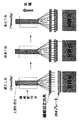
また、本発明の充填方法によれば、複数本の中空繊維を束ねた中空繊維束(繊維配列体)の各中空繊維に一度にゲル形成性溶液を充填することも可能である。公知の方法、例えば、特開2000−270878号公報記載の方法に従い、繊維配列体を作成する。次に、図5に示すよう繊維配列体の開口端部側を、繊維固定治具に固定する。繊維固定治具の下方には、昇降台上に複数のウェルからなるプレートが設置されている。ウェル部にゲル形成性溶液が添加されている。昇降台を上下することにより、繊維固定治具の固定された各中空繊維が、各ウェル内に保持されているゲル形成性溶液に浸漬し、先に述べた方法により充填操作が実施される。
【0028】
上記のごとく各中空繊維にゲル形成性溶液が充填され、中空部にゲルを形成することができる。このようにして作成されたゲル充填中空繊維配列体を繊維の長手方向と交叉する方向で切断をすることにより、生体関連物質マイクロアレイを製造することができる。
【0029】
【実施例】
以下、実施例により本発明をより詳細に説明する。
<実施例1> アクリルアミドゲルの中空繊維への充填
以下、図2を使用して説明する。
1.充填準備
中空繊維として、ガラスキャピラリーA(フューズドシリカ製、内径150μm、長さ30cm)を用意した。その片側の口をエポキシ樹脂で密封した。次に、充填するアクリルアミドモノマー溶液を入れた20cc容器B及び充填用チャンバーとして用いる2Lの3つ口セパラタブルフラスコCを用意した。アクリルアミドモノマー溶液の調製方法は以下の通りである。
【0030】
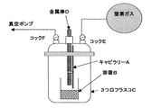
アクリルアミド(アルドリッチ社製)150mg及びメチレンビスアクリルアミド(アルドリッチ社製)8mgを10分間超音波脱気した蒸留水1840mgに溶解した後、過硫酸カリウム10%水溶液を2mg添加した溶液を容器Bに入れた。次にガラスキャピラリーA及びモノマー溶液を入れた容器Bを3つ口フラスコCに設置し、3つ口フラスコCにはキャピラリーを固定する金属棒D、2方コックE、Fを2個所に取り付け、更にコックEには窒素を封入したバルーン、コックFには真空ポンプへの接続チューブをそれぞれ取り付けた。ガラスキャピラリーAは金属棒Dの先に固定し、更に金属棒Dはネジ式の止め具で減圧時に下がらないように固定した。
【0031】
2.溶液のキャピラリーへの充填
始めにフラスコC内を窒素置換するために以下の操作を行った。
まず、窒素バルーンをつないだコックEを閉め、真空ポンプにつないだコックFを開けてフラスコC内を30mmHgまで減圧した。次にコックFを閉め、コックEを開けてフラスコC内を780mmHgまで加圧した。その後同様の減圧及び加圧操作を5回繰り返した。次にもう一度コックEを閉め、コックFを開けてフラスコC内を20mmHgまで減圧した後、コックFを閉め、金属棒Dのネジ固定式留め具を緩めて金属棒をキャピラリーAの先端の口が溶液に十分に浸漬するまでフラスコC内に押し下げて再びネジをしっかり締めて固定した。次にコックEを開いてフラスコ内を780mmHgまで加圧した。加圧操作後、溶液はキャピラリーのほぼ密封された位置まで充填された。次にフラスコCを70℃の恒温槽に移し、3時間重合せしめ、ゲル充填キャピラリーを得た。
【0032】
<実施例2> DNAマイクロアレイの作成
以下、図4を使用して説明する。
1.中空繊維配列体及び充填溶液の準備
三菱エンジニアリング(株)製のポリカーボネートを溶融紡糸して得た長さ60cmの非多孔質中空繊維(内径160μm、外径280μm)384本を8×24に配列させてウレタン樹脂で固めた繊維配列体を用意し、その繊維配列体の一方の口を384本すべて樹脂で塞いだ。次に充填する溶液としてジメチルアクリルアミド9部、メチレンビスアクリルアミド1部からなる15%水溶液を6cc調製し、更に10%アゾ系開始剤溶液(和光純薬社製VA044)を6μl加えた重合溶液を作成した。次にこの重合液を15μlに2pmol/μlの末端アクリルアミド修飾DNA(商品名アクリダイト:ユーロジェンティック社)溶液5μlを混合したものを384プレートの各ウェルに分注したものを用意し、前記繊維配列体と供に遠隔操作が可能な空気圧式昇降台を具備した真空乾燥機内に入れ、溶液を分注した384プレートは乾燥機内の昇降台の上に配置し、繊維配列体は各糸先が384プレートの各ウェルに入るように専用の固定治具で固定して配置した。
【0033】
2.充填重合操作方法
充填重合用のチャンバーとして市販の真空乾燥機を用い、これに窒素吹き込みライン及び真空ラインを以下の通り接続した。
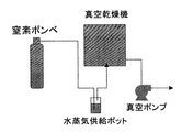
初めに真空乾燥機内を窒素置換するために真空乾燥機のパージラインに窒素ガスの供給ラインを接続し、真空ラインは真空ポンプに接続した。更に窒素ガスラインには窒素ガスを飽和水蒸気圧にするための水蒸気供給ポット(図3参照)を窒素ラインの途中に設置した。次に真空ポンプで乾燥機内を30mmHgまで減圧した後、窒素ガスをパージラインより乾燥機内に吹き込み、780mmHgまで加圧した。その後同様の減圧及び加圧操作を5回繰り返して乾燥機内を窒素ガス雰囲気にした。次にもう一度真空ポンプで20mmHgまで減圧した後、遠隔操作にて昇降台を引き上げて繊維配列体の各糸先を384プレートの各ウェル中の溶液に浸漬させた。次いで再度窒素ガスを吹き込んで乾燥機内圧力を780mmHgまで加圧した後、窒素ガスを3L/min.の流量で乾燥機に供給しながら温度を55℃に設定して昇温を開始し、そのまま3時間重合を行った。
【0034】
3.配列体の薄片化
上記の充填重合操作で得られたゲル充填繊維配列体を繊維軸方向に対して垂直方向にミクロトームで厚さ500μmに薄片化することで、各中空繊維に仕切られた中にDNA断片が固定化されたゲルのスポットが8×24に配列されたDNAマイクロアレイを得た。
【0035】
【発明の効果】
キャピラリーの片端側を密封することにより、ゲル形成性溶液のキャピラリーへの充填を正確且つ簡便に行うことが可能となる。また、キャピラリーが複数本、集束固定化した繊維配列体の各繊維にゲル形成性溶液を充填するに好適な方法である。
【図面の簡単な説明】
【図1】一端を封止した中空繊維の内部を減圧状態とし、中空繊維の開放端を溶液に浸漬して加圧することにより、中空繊維内部に溶液が充填されることを示す図である。
【図2】充填用チャンバーの一例を示す図である。
【図3】本発明の方法を実施するための装置の一例である。
【図4】水蒸気供給ポットの一例を示す図である。
【図5】繊維配列体の各繊維に溶液を充填する方法を示す図である。[0001]
TECHNICAL FIELD OF THE INVENTION
The present invention relates to a method for filling a capillary such as a capillary or a hollow fiber with a gel, and a method for producing a gel-filled hollow fiber. The gel-filled hollow fiber is used for capillary gel electrophoresis, DNA microarray, and the like.
[0002]
[Prior art]
Capillary gel electrophoresis is widely used for separation analysis of sugar chains, optical resolution, gene sequence analysis, and the like. In recent years, due to the full-fledged human genome project, it has been widely used in the field of genome analysis, for example, gene expression analysis, polymorphism analysis of SNPs and the like, and proteome analysis.
[0003]
As an example of gene expression analysis, a gel-filled capillary in which a probe such as a DNA fragment derived from a useful gene has been immobilized on a gel is prepared, a sample is introduced into the capillary, and the interaction with the probe is observed. Attempts have been made (see JP-A-3-47097).
[0004]
Furthermore, gel-filled capillaries are also used as components of DNA microarrays. This microarray is obtained by cutting a block body including a plurality of gel-filled capillaries arranged in an orderly manner in a direction crossing the longitudinal direction of the capillaries. This microarray is partitioned by each capillary, and a gel is held in the partition. The capture probe is held on a gel.
[0005]
In any of the above cases, it is necessary to fill the capillary with the gel. As a method of filling the gel, a method of pressing the gel solution into the capillary by applying pressure (for example, Japanese Patent Application Laid-Open Nos. 196603), a method of sucking and sucking a gel solution into a capillary (decompression method: for example, JP-A-2000-32244), and a method of using both reduced pressure and pressure (for example, JP-A-3-31752). You.
[0006]
[Patent Document 1]
Japanese Patent Application Laid-Open No. 2-128158 [Patent Document 2]
JP-A-5-196603 [Patent Document 3]
JP 2000-322244 A [Patent Document 4]
JP-A-3-31752
[Problems to be solved by the invention]
Precise liquid volume control is required to fill the pore tube such as a capillary with a solution.However, any of the above publications is a method of filling a capillary with both ends open, so that the ejection of the liquid or There is a risk of leakage. For this reason, there is an example in which the amount of the filling liquid is controlled by pressurizing the capillary end on the opposite side from which the gel solution has been sucked up, but the apparatus becomes large-scale.
[0008]
In addition, if it is made of an optically transparent material such as a glass capillary, a method of detecting by an optical method is also possible, but if it is made of a light-shielding material such as a metal column, the above-mentioned solution means Can not be adopted.
[0009]
[Means for Solving the Invention]
In view of the above problems, the present inventors have conducted intensive studies and, as a result, have found a method for accurately and easily filling a capillary with a gel-forming solution by sealing one end of the capillary, and completed the present invention. I let it.
[0010]
In the present invention, the open end side of the hollow fiber whose one end is sealed is immersed in a gel-forming solution in a system under a reduced pressure atmosphere, and then a gas is sealed in the system so that the inside of the system is reduced from a reduced pressure atmosphere to a normal pressure or higher. And filling the hollow fiber hollow portion with the solution by applying a pressurized atmosphere as described in (1), and gelling the filled solution in the hollow fiber hollow portion.
[0011]
Further, the present invention is a method for producing a gel-filled hollow fiber including the following steps.
(1) A step of immersing the open end of the hollow fiber with one end sealed in a gel-forming solution in a system under a reduced pressure atmosphere.
(2) A step of changing the system from a reduced-pressure atmosphere to a pressurized atmosphere of normal pressure or more, and filling the hollow portion of the hollow fiber with a gel-forming solution.
(3) A step of gelling the gel-forming solution filled in the hollow portion of the hollow fiber.
[0012]
Further, the gel-filled hollow fiber produced by the above method is used as a constituent member of a biologically relevant substance microarray.
That is, the present invention is a method for producing a biologically relevant substance microarray including the following steps.
(1) A step of bundling a plurality of gel-filled hollow fibers produced by the method according to claim 9 to form a fiber array.
(2) a step of cutting the fiber array in a direction crossing the longitudinal direction of the fiber;
[0013]
Further, the present invention is a method for producing a biologically relevant substance microarray including the following steps.
(1) A step of bundling a plurality of hollow fibers to form a fiber array.
(2) A step of filling the hollow portion of each hollow fiber of the fiber array with a gel-forming solution according to the method of claim 5.
(3) a step of cutting the fiber array in a direction crossing the longitudinal direction of the fiber.
[0014]
BEST MODE FOR CARRYING OUT THE INVENTION
In the present invention, the “gel-forming solution” is a solution containing a reactive substance such as a gel-forming polymerizable monomer, and the solution becomes a gel by polymerizing and cross-linking the monomer and the like. Solution. Such monomers include acrylamide, dimethylacrylamide, vinylpyrrolidone, methylenebisacrylamide, and the like. In this case, the solution may contain a polymerization initiator and the like.
[0015]
The “gel-forming solution” of the present invention also includes a temperature-dependent reversible gel such as agarose, that is, a solution that can be gelled by cooling. Water and the like are mentioned as a solvent of the gel-forming solution.
[0016]
Further, the gel-forming solution of the present invention may contain a biological substance. Examples of the biological substance include nucleic acids (DNA, RNA, etc.), amino acids, peptides, proteins, sugars, lipids, and the like.
[0017]
These bio-related substances are fixed to a gel by a known method. For example, when a polymerizable monomer is used as a gel component, by introducing an unsaturated functional group into a bio-related substance, it can be fixed to the gel component by a copolymerization reaction with the monomer component. When agarose is used, it is also possible to immobilize a biological substance by utilizing avidin-biotin specific binding.
[0018]
In the present invention, the term "hollow fiber" refers to a macaroni-like fiber having a hollow inside, and is used synonymously with ultrafine tubes, capillaries, hollow fibers, and the like.
The raw material used for the hollow fiber may be any of an organic material and an inorganic material as long as it can be processed into a hollow fiber. For example, various polyamide-based fibers such as nylon 6, nylon 66, aromatic polyamide, and polyethylene terephthalate Polyester fibers such as polybutylene terephthalate, polylactic acid, polyglycolic acid, and polycarbonate; acrylic fibers such as polyacrylonitrile; polyolefin fibers such as polyethylene and polypropylene; polymethacrylates such as polymethyl methacrylate -Based fibers, polyvinyl alcohol-based fibers, polyvinylidene chloride-based fibers, polyvinyl chloride-based fibers, polyurethane-based fibers, phenol-based fibers, fluorine made of polyvinylidene fluoride, polytetrafluoroethylene, etc. Fibers, polyalkylene para oxybenzoate material such system can be used.
[0019]
When the hollow fiber is used as a component of a device using the optical detection means, a transparent one is preferable. Such materials include polycarbonate-based materials and polymethyl methacrylate-based materials.
The outer diameter of the hollow fiber is 2 mm or less, preferably 1 mm or less. The inner diameter is preferably from 0.2 mm to 1.0 mm.
[0020]
The hollow fiber has an opening at one end hermetically sealed. Sealing and sealing are not particularly limited as long as airtightness is maintained under any of pressurized and depressurized conditions. Generally, a method of sealing the opening by heat fusion or pouring a resin is employed.
[0021]
Next, the hollow part of the hollow fiber whose one end is sealed as described above is filled with a gel-forming solution.
Specifically, a container containing the hollow fiber and the gel-forming solution is provided in a system in which the pressure, temperature, and the like can be adjusted, for example, in a chamber. The chamber used here is not particularly limited as long as vacuum / decompression and heating can be performed. For example, a commercially available vacuum dryer, a laboratory glass reactor, or the like can be used. The pressure at the time of depressurization is a pressure necessary for sufficiently filling the gel-forming solution to a sealed position at one end of the hollow fiber. The pressure is appropriately selected depending on the length of the hollow fiber, the inner diameter of the hollow fiber, the clay of the gel-forming solution, and the like. Preferably it is 50 mmHg, more preferably 30 mmHg or less.
[0022]
Next, the open end side of the hollow fiber is immersed in a gel-forming solution. As a method for immersion, for example, the hollow fiber is installed in the chamber such that the opening on the open end side faces downward, and a container containing a gel-forming solution is installed below the hollow fiber. For example, if the container is placed on a lifting platform, the hollow fiber can be immersed in the solution by moving the lifting platform up and down. It is also possible to immerse the hollow fiber in the solution by moving it up and down. The lifting platform is not particularly limited, but is preferably a pneumatically or hydraulically operated lifting platform.
[0023]
The timing of immersing the opening of the hollow fiber in the gel-forming solution may be before or after the inside of the system is placed under a reduced pressure atmosphere. Since bubbles may be generated in the solution and the bubbles may be mixed into the filling liquid, it is preferable to perform the pressure reduction operation and then perform the immersion operation.
[0024]
Next, in a state where the opening of the hollow fiber is immersed in the gel-forming solution, the pressure (atmospheric pressure) in the system is increased from a reduced pressure to a normal pressure or less, so that a pressure difference between the inside and the outside of the hollow fiber hollow portion causes The hollow part of the hollow fiber is filled with the gel-forming solution (see FIG. 1). In this pressurizing step, the pressure in the system is not particularly limited as long as it is equal to or higher than normal pressure, but is preferably 760 mmHg to 1000 mmHg. The pressurizing operation can be performed, for example, by introducing a gas into the system. As the gas, for example, when a solution containing an acrylamide-based monomer is used as the gel-forming solution, an inert gas that does not inhibit the polymerization reaction or the gel-forming reaction is preferable. Specifically, they are nitrogen gas and argon gas.
[0025]
Furthermore, when a hollow fiber of polymethyl methacrylate or polycarbonate is used as the hollow fiber, since the water vapor permeability is higher than that of a hollow fiber made of an inorganic material, drying of the gel during or after gel formation becomes a problem. There are cases. In order to solve such a problem, it is preferable that the inside of the system be saturated with steam pressure during the filling operation. As a method for saturating the water vapor pressure, for example, when the inside of the system is pressurized by filling the gas with a solution by filling the hollow portion with a gas, a gas is passed through a water vapor pot as shown in FIG. As a result, a gas saturated with water vapor can be introduced into the system, and the inside of the system can be saturated with water vapor pressure. It is also possible to supply water directly into the system after the filling operation is completed. When supplying water directly, it is possible to efficiently saturate the humidity in the system by blowing it into a mist.
After the filling operation is completed as described above, the gel-filled hollow fiber can be produced by performing polymerization and gelation by a known method.
[0026]
In addition, a gel-filled hollow fiber is produced as described above using a gel containing a bio-related substance, and a plurality of hollow fibers into which the gel containing a bio-related substance is introduced are bundled and fixed, and the length of the fiber is fixed. By cutting in a direction crossing the direction (fiber axis direction), a biologically relevant substance microarray can be manufactured.
[0027]
Further, according to the filling method of the present invention, it is also possible to fill each hollow fiber of a hollow fiber bundle (fiber array) obtained by bundling a plurality of hollow fibers with the gel-forming solution at once. A fiber array is prepared according to a known method, for example, a method described in JP-A-2000-27078. Next, as shown in FIG. 5, the opening end side of the fiber array is fixed to a fiber fixing jig. Below the fiber fixing jig, a plate made up of a plurality of wells is placed on a lifting table. A gel-forming solution is added to the well. By moving the lifting table up and down, each hollow fiber fixed by the fiber fixing jig is immersed in the gel-forming solution held in each well, and the filling operation is performed by the method described above.
[0028]
As described above, each hollow fiber is filled with the gel-forming solution, and a gel can be formed in the hollow portion. By cutting the gel-filled hollow fiber array produced in this manner in a direction crossing the longitudinal direction of the fiber, a biologically relevant substance microarray can be manufactured.
[0029]
【Example】
Hereinafter, the present invention will be described in more detail with reference to examples.
<Example 1> Filling of acrylamide gel into hollow fibers Hereinafter, description will be made with reference to Fig. 2.
1. Glass capillary A (made of fused silica, inner diameter 150 μm, length 30 cm) was prepared as a filling preparation hollow fiber. One side of the mouth was sealed with epoxy resin. Next, a 20 cc container B containing an acrylamide monomer solution to be filled and a 2 L three-neck separable flask C used as a filling chamber were prepared. The method for preparing the acrylamide monomer solution is as follows.
[0030]
After dissolving 150 mg of acrylamide (manufactured by Aldrich) and 8 mg of methylenebisacrylamide (manufactured by Aldrich) in 1840 mg of distilled water which was ultrasonically degassed for 10 minutes, a solution to which 2 mg of a 10% aqueous solution of potassium persulfate was added was placed in Container B. . Next, the glass capillary A and the container B containing the monomer solution are set in a three-necked flask C, and the three-necked flask C is provided with two metal rods D and two-way cocks E and F for fixing the capillaries, Further, a balloon filled with nitrogen was attached to the cock E, and a connection tube to a vacuum pump was attached to the cock F. The glass capillary A was fixed at the tip of a metal rod D, and the metal rod D was further fixed with a screw-type stopper so as not to fall during depressurization.
[0031]
2. At the beginning of the filling of the solution into the capillary, the following operation was performed to replace the inside of the flask C with nitrogen.
First, the cock E connected to a nitrogen balloon was closed, and the cock F connected to a vacuum pump was opened to reduce the pressure in the flask C to 30 mmHg. Next, the cock F was closed, the cock E was opened, and the inside of the flask C was pressurized to 780 mmHg. Thereafter, the same decompression and pressurization operations were repeated five times. Next, the cock E was closed again, the cock F was opened, the pressure in the flask C was reduced to 20 mmHg, the cock F was closed, the screw-type fastener of the metal rod D was loosened, and the end of the capillary A was closed. It was pushed down into flask C until it was fully immersed in the solution, and the screw was tightened and fixed again. Next, the cock E was opened and the inside of the flask was pressurized to 780 mmHg. After the pressurization operation, the solution was filled up to a substantially sealed position of the capillary. Next, the flask C was transferred to a constant temperature bath at 70 ° C. and polymerized for 3 hours to obtain a gel-filled capillary.
[0032]
<Example 2> Preparation of DNA microarray A description will be given below with reference to Fig. 4.
1. Preparation of Hollow Fiber Array and Filling Solution 384 nonporous hollow fibers (inner diameter 160 μm, outer diameter 280 μm) of 60 cm in length obtained by melt-spinning polycarbonate manufactured by Mitsubishi Engineering Co., Ltd. are arranged in an 8 × 24 arrangement. A fiber array solidified with urethane resin was prepared, and one opening of the fiber array was closed with 384 resin pieces. Next, 6 cc of a 15% aqueous solution consisting of 9 parts of dimethylacrylamide and 1 part of methylenebisacrylamide was prepared as a solution to be filled, and a polymerization solution was prepared by further adding 6 μl of a 10% azo-based initiator solution (VA044 manufactured by Wako Pure Chemical Industries, Ltd.). did. Next, a mixture of 15 μl of this solution and 5 μl of a 2 pmol / μl terminal acrylamide-modified DNA (trade name: Acrydite: Eurogentic) solution was dispensed into each well of a 384 plate to prepare the fiber array. The 384 plate into which the solution was dispensed was placed in a vacuum dryer equipped with a pneumatic elevator capable of remote operation together with the body, and the plate was placed on the elevator in the dryer. The plate was fixed and fixed with a dedicated fixing jig so as to enter each well of the plate.
[0033]
2. Packing polymerization operation method A commercially available vacuum dryer was used as a chamber for the packing polymerization, and a nitrogen blowing line and a vacuum line were connected to the chamber as follows.
First, a nitrogen gas supply line was connected to a purge line of the vacuum dryer to replace the inside of the vacuum dryer with nitrogen, and the vacuum line was connected to a vacuum pump. Further, a steam supply pot (see FIG. 3) for setting the nitrogen gas to a saturated steam pressure was installed in the nitrogen gas line in the middle of the nitrogen line. Next, the pressure inside the dryer was reduced to 30 mmHg by a vacuum pump, and then nitrogen gas was blown into the dryer from a purge line to pressurize the dryer to 780 mmHg. Thereafter, the same depressurizing and pressurizing operations were repeated five times to make the inside of the dryer a nitrogen gas atmosphere. Next, the pressure was again reduced to 20 mmHg by a vacuum pump, and then the lifting platform was pulled up by remote control to immerse each thread end of the fiber array in the solution in each well of the 384 plate. Next, nitrogen gas was blown again to increase the internal pressure of the dryer to 780 mmHg, and then nitrogen gas was supplied at 3 L / min. The temperature was set to 55 ° C. while supplying to the drier at a flow rate of, and the temperature was raised, and polymerization was carried out for 3 hours.
[0034]
3. The gel-filled fiber array obtained by the above-described filling polymerization operation was sliced to a thickness of 500 μm with a microtome in a direction perpendicular to the fiber axis direction, so that each hollow fiber was partitioned. A DNA microarray in which the spots of the gel on which the DNA fragments were immobilized were arranged in 8 × 24 was obtained.
[0035]
【The invention's effect】
By sealing one end side of the capillary, it is possible to accurately and simply fill the capillary with the gel-forming solution. Further, this is a method suitable for filling a gel-forming solution into each fiber of a fiber array in which a plurality of capillaries are bundled and fixed.
[Brief description of the drawings]
FIG. 1 is a view showing that the inside of a hollow fiber is filled with a solution by evacuating the open end of the hollow fiber into a solution and pressurizing the inside of the hollow fiber with one end sealed.
FIG. 2 is a diagram showing an example of a filling chamber.
FIG. 3 is an example of an apparatus for performing the method of the present invention.
FIG. 4 is a diagram illustrating an example of a steam supply pot.
FIG. 5 is a diagram showing a method for filling each fiber of the fiber array with a solution.
Claims (11)
(1)一端を密封した中空繊維の開放端を減圧雰囲気の系内でゲル形成性溶液に浸漬する工程。
(2)系内を減圧雰囲気から常圧以上の加圧雰囲気とし、中空繊維中空部にゲル形成性溶液を充填する工程。
(3)中空繊維中空部に充填されたゲル形成性溶液をゲル化する工程。A method for producing a gel-filled hollow fiber, comprising the following steps.
(1) A step of immersing the open end of the hollow fiber whose one end is sealed in a gel-forming solution in a system under a reduced pressure atmosphere.
(2) A step in which the system is changed from a reduced pressure atmosphere to a pressurized atmosphere of normal pressure or higher, and the hollow portion of the hollow fiber is filled with the gel-forming solution.
(3) A step of gelling the gel-forming solution filled in the hollow portion of the hollow fiber.
(1)請求項9記載の方法により得られるゲル充填中空繊維を複数本、集束し、繊維配列体を形成する工程。
(2)該繊維配列体を繊維の長手方向と交叉する方向で切断する工程。A method for producing a biologically relevant substance microarray, comprising the following steps.
(1) A step of bundling a plurality of gel-filled hollow fibers obtained by the method according to claim 9 to form a fiber array.
(2) a step of cutting the fiber array in a direction crossing the longitudinal direction of the fiber;
(1)複数本の中空繊維を集束し、繊維配列体を形成する工程。
(2)請求項5の方法により、該繊維配列体の各中空繊維中空部にゲル形成性溶液を充填する工程。
(3)該繊維配列体を繊維の長手方向と交叉する方向で切断する工程。A method for producing a biologically relevant substance microarray, comprising the following steps.
(1) A step of bundling a plurality of hollow fibers to form a fiber array.
(2) A step of filling the hollow part of each hollow fiber of the fiber array with a gel-forming solution by the method of claim 5.
(3) a step of cutting the fiber array in a direction crossing the longitudinal direction of the fiber.
Priority Applications (1)
| Application Number | Priority Date | Filing Date | Title |
|---|---|---|---|
| JP2002328179A JP2004163211A (en) | 2002-11-12 | 2002-11-12 | Method of filling gel into hollow fiber, hollow fiber filled with gel, and organism-related substance microarray using the same |
Applications Claiming Priority (1)
| Application Number | Priority Date | Filing Date | Title |
|---|---|---|---|
| JP2002328179A JP2004163211A (en) | 2002-11-12 | 2002-11-12 | Method of filling gel into hollow fiber, hollow fiber filled with gel, and organism-related substance microarray using the same |
Publications (1)
| Publication Number | Publication Date |
|---|---|
| JP2004163211A true JP2004163211A (en) | 2004-06-10 |
Family
ID=32806549
Family Applications (1)
| Application Number | Title | Priority Date | Filing Date |
|---|---|---|---|
| JP2002328179A Pending JP2004163211A (en) | 2002-11-12 | 2002-11-12 | Method of filling gel into hollow fiber, hollow fiber filled with gel, and organism-related substance microarray using the same |
Country Status (1)
| Country | Link |
|---|---|
| JP (1) | JP2004163211A (en) |
Cited By (7)
| Publication number | Priority date | Publication date | Assignee | Title |
|---|---|---|---|---|
| JP2006214982A (en) * | 2005-02-07 | 2006-08-17 | Biomolecular Engineering Research Institute | Affinitive polyacrylamide electrophoretic method |
| JP2007256037A (en) * | 2006-03-23 | 2007-10-04 | Gunma Prefecture | Gel for isoelectric point electrophoresis in two-dimensional electrophoretic system |
| JP2010122208A (en) * | 2008-10-20 | 2010-06-03 | Mitsubishi Rayon Co Ltd | Method for manufacturing gel-filled array and method for manufacturing biochip |
| WO2013165018A1 (en) | 2012-05-02 | 2013-11-07 | 三菱レイヨン株式会社 | Probe or probe set for evaluating influence of ultraviolet ray on skin, and nucleic acid microarray |
| WO2018168816A1 (en) | 2017-03-14 | 2018-09-20 | 株式会社ジーシー | Dna chip for detecting dental caries bacteria |
| WO2019088272A1 (en) | 2017-11-02 | 2019-05-09 | 三菱ケミカル株式会社 | Intra-oral inspection method using information for bacteria groups associated with clinical indices |
| WO2019088271A1 (en) | 2017-11-02 | 2019-05-09 | 三菱ケミカル株式会社 | Method for estimating inflammation area of periodontal pockets |
-
2002
- 2002-11-12 JP JP2002328179A patent/JP2004163211A/en active Pending
Cited By (8)
| Publication number | Priority date | Publication date | Assignee | Title |
|---|---|---|---|---|
| JP2006214982A (en) * | 2005-02-07 | 2006-08-17 | Biomolecular Engineering Research Institute | Affinitive polyacrylamide electrophoretic method |
| JP4595575B2 (en) * | 2005-02-07 | 2010-12-08 | 三菱化学株式会社 | Affinity polyacrylamide electrophoresis |
| JP2007256037A (en) * | 2006-03-23 | 2007-10-04 | Gunma Prefecture | Gel for isoelectric point electrophoresis in two-dimensional electrophoretic system |
| JP2010122208A (en) * | 2008-10-20 | 2010-06-03 | Mitsubishi Rayon Co Ltd | Method for manufacturing gel-filled array and method for manufacturing biochip |
| WO2013165018A1 (en) | 2012-05-02 | 2013-11-07 | 三菱レイヨン株式会社 | Probe or probe set for evaluating influence of ultraviolet ray on skin, and nucleic acid microarray |
| WO2018168816A1 (en) | 2017-03-14 | 2018-09-20 | 株式会社ジーシー | Dna chip for detecting dental caries bacteria |
| WO2019088272A1 (en) | 2017-11-02 | 2019-05-09 | 三菱ケミカル株式会社 | Intra-oral inspection method using information for bacteria groups associated with clinical indices |
| WO2019088271A1 (en) | 2017-11-02 | 2019-05-09 | 三菱ケミカル株式会社 | Method for estimating inflammation area of periodontal pockets |
Similar Documents
| Publication | Publication Date | Title |
|---|---|---|
| JP5441142B2 (en) | Microfluidic planar lipid bilayer array and analytical method using the planar lipid bilayer membrane | |
| US5840388A (en) | Polyvinyl alcohol (PVA) based covalently bonded stable hydrophilic coating for capillary electrophoresis | |
| JP4859071B2 (en) | Instruments for assay, synthesis, and storage, and methods of making, using, and operating the same | |
| WO1996023220A9 (en) | Polyvinyl alcohol (pva) based covalently bonded stable hydrophilic coating for capillary electrophoresis | |
| US20140011703A1 (en) | Automatic injection device for microarray chip and automatic injection hybridization microarray chip | |
| JP6029366B2 (en) | Integrated cartridge for pretreatment / electrophoresis, pretreatment integrated capillary electrophoresis apparatus, and pretreatment integrated capillary electrophoresis method | |
| JP2000508763A (en) | Acrylic microchannels and their use in electrophoretic applications | |
| AU5635190A (en) | Casting of gradient gels | |
| JPH04232456A (en) | Separating-column preparing method and separating-column preparing system | |
| EP0427845A1 (en) | Gel casting method and apparatus | |
| JP2004163211A (en) | Method of filling gel into hollow fiber, hollow fiber filled with gel, and organism-related substance microarray using the same | |
| US20010023827A1 (en) | Copolymers capillary gel electrophoresis | |
| CN110982011A (en) | Light-directing bending material and preparation method thereof | |
| JP2004524540A (en) | Electrophoresis separation system | |
| JPH04315046A (en) | Micro-column for gel electrophoresis and manufacture thereof | |
| EP0494958B1 (en) | Gel packed columns suitable for use in chromatography | |
| JP2011133470A (en) | Biomolecule immobilization array having biomolecule immobilization carrier consisting of hydrophilic gel | |
| JP5349241B2 (en) | Method for producing gel-filled array and method for producing biochip | |
| JP2001248072A (en) | Method for treating inner wall part of hollow fiber and method for packing gel | |
| JPH11230936A (en) | Device for filling gel into capillary column | |
| US20210369647A1 (en) | Micro-solid phase extraction | |
| Liang et al. | Formation of concentration gradient and its application to DNA capillary electrophoresis | |
| CN113063834B (en) | Method for visually detecting substance concentration based on mobile exchange interface | |
| JP5660468B2 (en) | Method for producing gel microarray for detecting bio-related substances | |
| US20220080410A1 (en) | Pre-Shaping Fluidic Sample in a Planar Way Before Processing |