JP2004160980A - Synchronizing processing for printing constituent element - Google Patents
Synchronizing processing for printing constituent element Download PDFInfo
- Publication number
- JP2004160980A JP2004160980A JP2003180046A JP2003180046A JP2004160980A JP 2004160980 A JP2004160980 A JP 2004160980A JP 2003180046 A JP2003180046 A JP 2003180046A JP 2003180046 A JP2003180046 A JP 2003180046A JP 2004160980 A JP2004160980 A JP 2004160980A
- Authority
- JP
- Japan
- Prior art keywords
- image
- mark
- image plane
- marks
- planes
- Prior art date
- Legal status (The legal status is an assumption and is not a legal conclusion. Google has not performed a legal analysis and makes no representation as to the accuracy of the status listed.)
- Pending
Links
Images


Classifications
-
- G—PHYSICS
- G06—COMPUTING; CALCULATING OR COUNTING
- G06K—GRAPHICAL DATA READING; PRESENTATION OF DATA; RECORD CARRIERS; HANDLING RECORD CARRIERS
- G06K15/00—Arrangements for producing a permanent visual presentation of the output data, e.g. computer output printers
-
- G—PHYSICS
- G06—COMPUTING; CALCULATING OR COUNTING
- G06K—GRAPHICAL DATA READING; PRESENTATION OF DATA; RECORD CARRIERS; HANDLING RECORD CARRIERS
- G06K2215/00—Arrangements for producing a permanent visual presentation of the output data
- G06K2215/0082—Architecture adapted for a particular function
- G06K2215/0091—Outputting only video data, e.g. Hard copy of CRT display
Landscapes
- Engineering & Computer Science (AREA)
- General Engineering & Computer Science (AREA)
- Physics & Mathematics (AREA)
- General Physics & Mathematics (AREA)
- Theoretical Computer Science (AREA)
- Editing Of Facsimile Originals (AREA)
- Record Information Processing For Printing (AREA)
- Accessory Devices And Overall Control Thereof (AREA)
- Facsimiles In General (AREA)
- Inking, Control Or Cleaning Of Printing Machines (AREA)
- Image Processing (AREA)
- Image Analysis (AREA)
Abstract
Description
【技術分野】
本発明は、デジタル印刷装置に関し、より詳しくは、フォームの完全な部分を構成する全ての成分が同期していることを検出するための技術に関する。
【背景技術】
デジタル印刷装置では、文書は、多数のフォーム(組み版)から構成され得る。フォームの各々は、複数のイメージから構成され得る。各イメージは、複数のイメージ平面から構成され得る。これらの用語は、印刷産業で一般に使用されているが、これらの用語の意味は、厳密に定義されているわけではなく、様々に用いられがちである。本明細書では、例えばページ等の、印刷媒体の物理的部分の意味を示す。フォームは、1つ又は2つの側面を持ち得る。フォーム原点は、フォームの一番上の地点である。一方、指示マークは、ピン送り指示のための物理的標識又は論理演算上の位置であり、フォーム原点を同定するものである。文書は、例えば本又は複数ページの請求書等の、論理的に関連づけられた一連のフォームとして定義され得る。印刷物は、一連の文書として定義され得る。文書は、巻き取りが巳を横切って2列に印刷される複数のフォームから構成される場合がある。フォームの一側面に印刷された情報は、イメージである。一方、イメージ平面は、単一の印刷手段により印刷されたイメージの「レイヤー(層)」である。例えば、処理されたカラー印刷物では、CYMKの各色が、一つの印刷手段(印刷エンジン)により、別のイメージ平面に印刷される。印刷手段は、一つのイメージ平面又は一つのイメージ平面の一部分を印刷する、印刷ヘッド等のマーキング装置である。AFP/IPDS(アドバンスド・ファンクション・プリンティング/インテリジェント・プリンティング・データ・ストリーム)環境下では、OCA(オブジェクト・コンテント・アーキテクチャー)カラーの各々は、別のイメージ平面内にある。イメージ平面整合(IPC)マークは、イメージ平面と関連づけられた標識を言う。複合イメージグループ(CIG)マークは、フォーム内の各イメージ平面のための一つのIPCマークから構成されるIPCマークの組である。
フォームの幅は、印刷手段の印刷領域より大きい場合があり、複数の印刷手段が、完全なフォームを構成するため並列に一緒に編成され得る。非常に単純な文書では、複数の連続フォームの各々が、フォームの一側面にのみ印刷される一つのイメージ平面から構成されるものであり得る。このような文書は、一般に単一の印刷手段を使用して印刷されるので、この場合には、同期化は問題とならない。しかし、多くの文書は、より複雑であり、各フォームを形成するため、複数の印刷手段を必要とする。この典型例は、多色で印刷される2側面のフォーム(両面フォーム)、又は、複数編成の印刷手段から構成されたフォームである。印刷手段が、互いに同期していない可能性、又は印刷手段のいずれかに送られたデータが同期していない可能性がある。この結果、複数のイメージ又は複数のイメージの部分は、もはや、適切なフォームへと適切に同期しなくなってしまう。この不正確な同期の結果は、一般に非常に重大であり、この状態を検出するための測定手段が必要である。
同期化を検出し処理するための様々な方法が存在する。例えば、印刷装置の中には、フォームの各側面に、バーコード又はデータを含んだ他のマークを印刷し、当該フォームが印刷された後に、当該コード又はマークを読み取って、これらが適切に同期化されていることを保証しているものがある。同期化を検出するための現存する方法は、特定のマークの印刷、当該マークを読み取るためのリーダー又はスキャナー、及び、当該マークを解釈し、その結果を評価するためのソフトウェアを必要としている。このような装置は、単色の場合に適しているが、多数の印刷手段が使用される場合、即ち、2列の複合4色印刷物の場合は、非常に取り扱いにくいものである。
【発明の開示】
【発明が解決しようとする課題】
したがって、同期化を検出するための改良手段が、特に多色を用いた印刷において、必要とされている。
【課題を解決するための手段】
上記必要性に対処するため、本発明の同期化装置及び方法においては、媒体の部分についての適切な同期化の情報が検出可能され得る。本発明は、イメージを構成するイメージ平面の全てが適切に整合され、同じフォーム上に印刷されているか否かを検出する。本発明は、更に、フォームの前面及び背面の両方におけるイメージの同期化について、いかなるエラーをも検出する。本発明は、更に、イメージを構成するイメージ平面が、組み合わされた印刷手段を使用して印刷される場合のイメージ同期化において、いかなるエラーをも検出する。
本発明の一つの特徴によれば、印刷物について、各フォームの完成された部分を構成する構成要素の全てが同期して印刷されていることを検出し、又は、同期化エラーの場合には、エラー状態が通知されるための、方法が提供される。印刷物は、少なくとも1つのフォームを備え、各フォームは、1より多いイメージを含んでいてもよい。各イメージは、1以上のイメージ平面を含んでいてもよく、文書の各フォーム上のイメージが変わってもよい。
本発明によれば、各イメージは、各々の個々のイメージ平面と連係されたイメージ平面整合(IPC)マークの組から構成される複合イメージグループ(CIG)マークを含んでいる。IPCマークは、特定のイメージを構成する完全な組のイメージ平面が存在するか否かを決定することが、これらのマークの検査を介して可能となるように、各印刷手段により印刷される。各イメージ平面のためのIPCマークは、それらが重なり合わず、且つ、それらの相対位置が後でセンサーにより検出することができるような固定された既知の態様で互いに対してそれらが位置決めされるように、当該イメージ内に配置されている。IPCマークのための相対位置は、CIGマークの原点を基準とする。1組のIPCマークの適切な関係の検出は、有効なCIGマークを画成し、よって、完成されたイメージを画成する。しかし、当該イメージの同期性を判定するため、本発明は、発生して検出されることを必要とする追加の情報を提供する。
特定のフォームを構成する1組のイメージは、フォームの原点から同じ距離に配置された、各イメージに対するCIGマークの原点を持っている。連続するフォームに対して、フォーム原点からのCIGマークの距離は変化する。特定のフォーム上のイメージの全てが印刷された後、当該フォームと連係されたCIGマークは、センサーを用いて読み取られ、IPCマークの全てが有効であり、フォーム原点から同じ距離オフセットされているか否かが決定される。フォーム上のIPCマークの全てに対するフォーム原点からの距離が同じ場合、CIGマークは有効であり、「有効フォーム」を示す状態が形成される。「有効フォーム」状態の欠如は、当該フォーム上の情報が適切に整合されていないことを示すため印刷装置により使用される。
このおうに、本発明の目的は、印刷物における全てのフォームの全てのイメージの全てのイメージ平面の同期化の際におけるエラーを検出するための手段を提供することである。本発明の他の目的及び利点は、以下の説明、添付図面及び添付した請求の範囲から明らかとなろう。
【実施を実施するための最良の形態】
本発明は、フォーム上に印刷された情報の全てが適切に同期化されているか否かを検出する。この同期化は、媒体の前面又は背面の両方で検出可能である。本発明により提案された同期化検出は、1つまでの文書又は2つまでの文書、即ち単一文書又は二連文書に特に適しているが、任意のレイアウトの情報にまで拡張することができる。更には、本発明の説明は、1より多くの印刷手段を含む、デジタルインクジェット印刷装置に言及しているが、説明された問題及び該問題を検出するための方法は、1より多くの印刷手段を備えた任意のデジタル印刷装置に適用可能であることは、デジタルプリンターを理解している誰にとっても明らかであるべきである。
ここで、図1を参照すると、一連の連続フォーム10a、10b及び10cが示されている。各々の一例としてのフォームは、1つのイメージから構成され、各々が4つのイメージ平面12a、12b、12c、12d、14a、14b、14c、14d、16a、16b、16c、16d、18a、18b、18c、18dを備えている。例を用いて説明すると、これらのイメージ平面は、イメージのシアン、マゼンタ、イエロー、及び、ブラックの各部分に相当している。代替例は、一つの印刷手段が、フォームの左側を印刷し、第2の印刷手段がフォームの右側を印刷し、2つ以上の印刷手段がフォームの後方側を印刷するために使用されるシステムである。印刷するとき、多重イメージ平面は、結果として生じる複合イメージが意図されたイメージ平面から構成されるように適切に同期化されることが必要となる。1つ又はそれ以上の印刷手段が他のエンジンに対して同期化から外れる場合、又は、印刷手段に送られたデータが同期化から外れた場合、イメージ又は編成印刷手段の場合におけるイメージの一部分は、もはや適切に同期されなくなる。不正確な同期の結果は、一般に、その結果として生じたフォームが不正確なデータを含むということにおいて非常に重大である。
例を用いると、図2は、16a、16b及び16cにより表された第3のイメージ平面が「ずれて」しまっている状態を示している。よって、フォーム10aは、イメージ平面16aを無くしており、フォーム10b及び10cは、それらの上に以前のフォームからの第3のイメージ平面16a及び16bを各々持つことになる。これは、各フォーム上のイメージが不適切なイメージ平面から構成されている誤状態を生じさせる。各文書が先立つ文書と同じである、従来の印刷工程では、このようなずれは、ほとんど重大な影響をもたらさない。しかし、可変データが印刷されるとき、このようなずれは、非常に重大となり得る。例えば、印刷されている文書が財務諸表であった場合、このようなずれは、イメージ平面の一つが、別のイメージ平面に送られるであろう、次の文書上に印刷される財政記録の一部分を含むような結果をもたらし得る。このずれのエラーは、印刷される計算書を受け取る人間により直ちに検出されるが、印刷装置のオペレーターが検出することは難しい。更に、このようなずれは、典型的には、単一の文書ではなく、大きな印刷物で問題となる。
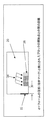
ここで、図3を参照すると、本発明は、各々のフォーム20上に整合マークを配置することを目的とし、当該目的は、当該フォームを構成する構成要素の全てが互いに関連して適切に調整されている場合に云うことができる。本発明によれば、フォーム20の各イメージの各イメージ平面は、当該イメージ平面を印刷するため使用されたのと同じ印刷手段により印刷される、イメージ平面整合(IPC)マーク24を含んでいる。図3では、イメージ平面整合マークは、各イメージ平面毎に異なる模様が描かれた矩形として示されている。即ち、それらは、この文書において互いから区別することができる。実際には、当業者により理解されるように、イメージ平面整合マークは、任意形状とすることができ、それらが存在するものとして、又は、存在しないものとして認識することができるかぎり、当該マークを完全に又は部分的に挿入することができる。好ましい実施形態では、イメージ平面整合マーク24は、中身が描かれた矩形であり、約1.6cm2(1/4インチ平方)以下とすることができる。フォーム上の各イメージに対して、当該イメージを構成するイメージ平面の全てに対して1組のイメージ平面整合マークが存在している。その結果生じた組は、複合イメージグループ(CIG)マークとなる。CIGマークの構成は、そのマークが、互いから既知のオフセット又は相対的配置で位置決めされるようになっている。IPCマークの配置は、データの用意か、又は、ラスターイメージプロセッサー(RIPS)によりデータに追加されるかのいずれかで達成することができる。
図4a及び図4bは、多重フォーム30a、30b、32a、32b、34a、34b、36a、36bを示しており、これらの各々は、連係されたCIGマーク26を持っている。一つのフォームからの複数のイメージ及びイメージの各部分が、別のフォーム上での同期化及び印刷からずれないことを確実にするため、図2の一例としての場合におけるように、フォームの間で差異が形成される。例えば、CIGマークの位置は、フォーム毎にばらついていてもよい。そのような方法は、連続するイメージのためのCIGマークが、フォームの原点又は指示マークから様々に異なる距離だけ変位されるべきことを要求する。図4aでは、各々のCIGマーク26は、フォームの頂部から異なる距離dで離れている。フォーム36a及び36bの頂部からのCIGマーク26の距離は、ゼロであり、一方、フォーム34a及び34bに対して、その距離はxであり、フォーム32a及び32bに対して、その距離は、x+yであり、最後に、フォーム30a及び30bに対して、その距離は、x+y+zである。ここで、z、y、zは、常にゼロよりも大きく、各々が、個々のIPCマークの幅よりも大きい。図4aでは、第1のフォームに対する距離dは、一つの原点にあり、この距離dは、CIGマークが連続する文書に対する原点から更に離れる方に移動し、次いで原点位置にリセットする状態で、周期的パターンで変動する。図4aの基本的設備において、CIG26の出発点のために4つの固定位置が選択され、位置27として標識が付与される。各々のCIGマーク位置の出発点は、少なくともIPCマークのサイズ分だけ以前のCIGマークよりも原点から更に離れている距離のところにある。CIGマークは、フォームからフォームへと異なる量だけ原点に対してシフトされるが、CIGマークを構成する個々のIPCマークの相対的配置は、常に同じままである。
フォームを構成するイメージ平面が適切に同期化される限り、CIGを構成するIPCマークは、他のIPCマークに対して適切な相対的配置を持つ。しかし、イメージ平面の一つが不適切に同期化されるようになると、当該イメージ平面と連係されたIPCマークの、他のイメージ平面のIPCマークに対する相対的配置は、不正確となる。例を用いると、CIGマークが、原点に対して4つの異なる位置を通してシフトされるシステムが考えられる。フォーム1に関するCIGが原点に位置し、フォーム2に関するCIGが原点から約5.2cm(2インチ)だけシフトされ、フォーム3に関するCIGが原点から約10.2cm(4インチ)だけシフトされ、フォーム4に関するCIGが原点から約15.ccm(6インチ)だけシフトされている。このパターンは、フォーム5上で、CIGマークが再び原点のところにあるように繰り返される。図4aでは、CIGマークの全てが完成し、IPCマークの全てが互いに対して適切に配置される。このことは、それらが適切に同期化されていることを示している。
図4bは、イメージ平面の一つが同期化から逸脱した場合を示している。これらのフォームの上側列に関するイメージ平面は、同期化されたままとなったおり、その結果、それらのCIGマークは完成し、全てのIPCマークが互いに対して適切に配置されている。フォーム1Bは正確であるが、フォーム2Bでは、同期化エラーが生じている。CIGブロックにおける第3のIPCマーク28aに対応するイメージ平面は、印刷ができなかった。その代わりに、当該イメージ平面は、1フォームだけ遅延され、フォーム3Bの一部分として印刷された。他のイメージ平面に対して適切に同期化されたならば、位置28aで印刷されたはずであったそのIPCマークは、今や28bで印刷されている。同様に、フォーム3Bの第3のIPCマークに対応するイメージ平面は、今やフォーム4Bの一部分として印刷されており、このため、そのIPCマークは、他のIPCマークと適切な空間的関係で印刷されないことになる。
第3のIPCマークが他のIPCマークに対して適切に配置されていないことを検出することにより、対応するイメージ平面が不適切にシフトされたことを容易に検出することができる。そのような検出は、後述されるように、システムオペレーターにより視覚的になすことができ、又は、電子センサーにより、なすことができる。
この例は、第3のIPCマークに対応するイメージ平面のシフトを検出することができることを示しているが、任意のイメージ平面のシフトを検出することができることは、当業者には明らかであろう。1より多いフォーム分のシフトも検出することができる。この例では、CIGは、フォームからフォームへ均一量でステップ移動されている。しかし、不均一なステップ移動を用いることもできる。本明細書の例は、原点に対して4つの位置を通して周期的に配置されるCIGマークをもっていた。しかし、より一般的には、他の周期長さを使用することができる。なお更に一般的には、CIGマークは、原点からランダム距離に配置することができる。
上記に示された例では、他のIPCマークに対する第3のIPCマークの配置におけるシフトを記述することにより、第3のIPCマークに対応するイメージ平面が1フォームだけ他のイメージ平面から遅延したことを決定することができた。一般には、CIGマークがフォームからフォームへ首尾一貫した態様でシフトされる実施例は、どのイメージ平面がシフトされたかのみではなく、どのくらいの量だけシフトされたかをも同定することを可能にする。このことが同定された場合、誤ったイメージ平面を適切な同期化状態へ戻すようにシフトするため、修正作用を取ることができる。図4bに示されたエラーに対しては、第3のIPCマークに対応するイメージ平面を1フォームだけ先に移動させることが必要となろう。それにより、これらのイメージ平面は、適切に同期化されることになる。この態様では、本発明は、同期化エラーを同定するための手段と、イメージ平面を再同期化するための手段とを提供する。
特定のフォームにおける同期化エラーの検出は、当該欠陥フォーム上に印刷されたマークを用いるか、又は、コンピュータ追跡処理のいずれかによって、それらのフォームにマーク又はラベルを付与することも可能にし、それにより、例えばエンベロープに挿入する間等の、印刷物の引き続く処置の間、これらの欠陥フォームを処置することができる。一つの好ましい実施例では、欠陥フォームが淘汰される段階において、これらの特定のフォームは、イメージ平面の一つにより印刷されるフォーム識別バーコードを用いて同定される。次に、欠陥フォームを再印刷することができる。各文書の全てのイメージ平面が適切に同期化されていることを確実にするため各文書を同定するバーコード及びCIGマークの組み合わせは、それらの印刷物が全体的に適切に印刷されたことの確信を印刷カスタマーに提供するため使用することができる。
フォームがその部分の全てと適切に同期化されているのみならず、それが文書用のイメージの適切なシーケンスにあることを決定することが望ましいことがある。例えば印刷シーケンス番号、バーコード又は文書の実際のシーケンスを表す口座番号、他のカスタマー若しくはクライアント同定シンボル等の他のマーク等の従来手段が、一般的である。本発明によれば、このシーケンス番号は、イメージ平面の一つだけに印刷されることを必要としている。よって、試験時には、単一イメージ平面のシーケンスは、正確であると決定され、本発明の教えを使用して、イメージ平面の全てが同期化されていると決定することができる場合には、イメージ平面の全てが適切なシーケンスにあることがわかる。
残念ながら、フォームからフォームへCIGマークが周期的に繰り返し配置されている場合、イメージ平面がCIGマークの繰り返し長さに等しい量だけシフトされるならば、エラーを検出することができない。上述された我々の一例としてのシステムに関し、4つのフォームにより他のイメージ平面を導くのがシアンイメージの場合、シアンイメージ平面のフォーム5が他のイメージ平面のフォーム1と共に印刷される。これらのフォームの両方のためのCIGマークが原点にあるとき、同期化エラーを検出することができない。代替の実施例では、CIGマークは、2つの連続的CIGマークが、同じオフセット距離には決して無いことを補償されるように、ランダムに即ち繰り返し距離では無くオフセットされる。このようにして、少なくとも数フォーム内で、任意のイメージ平面のずれ量の同期化エラーを検出することが可能となる。この実施例は、1組のフォームが繰り返され、当該繰り返しに合致する整合性においてエラーが発生する場合には、有利となる。
なお、CIGマークが交互に印刷されたフォーム上でのみ印刷される場合には、本発明を使用して同期化エラーを検出することができる。例えば、CIGマークが、図4aのフォーム1及び3等の奇数番号のフォーム上に印刷されるだけである場合には、イメージ平面の一つのフォーム分のずれは、何も印刷されるべきではない例えばフォーム2及び4等の偶数番号のフォーム上にIPCマークを印刷する結果をもたらす。このため、エラーの検出を、同様になすことができる。更には、文書当たりにして一度だけ文書を構成するフォームの同期化をチェックするためには、文書内の選択されたフォームにだけIPCマークを追加するが、文書それ自体にはIPCマークを印刷しないことは明らかであろう。例えば、IPCマークを、文書の間の分離頁上に印刷することができる。
図5に示されるように、CIGマークのインジケータ26の完全さを検査することによって、単一のCIGマークを構成するIPCマークの全てが存在することを検出するため、センサーが使用される。完全さは、検査時点で当該イメージのためのIPCマーク24の全てが互いに正しい関係にあることを示している。CIGマークのインジケータ26は、単一センサー38又は複数のセンサー38のいずれかで検出され得る。1つ又はそれ以上のセンサーは、IPCマークが互いに既知のオフセット関係で存在していることを検知する。IPCマークの適切な空間的関係が検出されて、信号即ち状態が完全さを示したとき、同期化イメージが良好なCIG(複合イメージグループ)状態を示していると主張することができる。当該フォームの原点からのCIGマーク構成要素の共通の空間的関係に起因して、フォームの検査は、当該フォームの任意の特定の時刻又は位置でなされる必要はない。IPCマーク全ての簡単な一致状態それ自体が、良好なフォームを示している。
本発明の利点は、印刷される媒体の前方側及び後方側の両方に、媒体の各側にIPCマーク24を印刷することにより同期化検出を適用することができる、ということである。CIG状態がフォームの両方の側に対して同時に存在する状態は、完成フォーム状態を示している。本発明の更なる利点は、多重フォームが連続するペーパーに亘って2まで(又はnまで)印刷されるところの文書の同期化を、互いに関して確証することができると共に、各フォームに対するイメージ平面の全てが連続するペーパーに亘る部分及び/又は原点に対する連続するペーパーの両側において厳密に同じ位置にそれらのCIGマークを配置させることを確実にするようにチェックすることができるということである。例えば、図4aでは、フォーム30a及び30bは、それらのCIGマークを、互いに対して等しく配置させている。これは、フォーム32a及び32b、フォーム34a及び34b、並びに、フォーム36a及び36bの場合に対してである。
上述された本発明の実施例では、IPCマークが、所定の容易に検出される空間的関係に従って互いに対して配置されていた。各フォームに対する、IPCマークの集まり、即ちCIGマークは、一つのフォームのマークを、他のフォームのマークから区別するため、原点に対してフォームからフォームへとシフトされた。少なくとも1つの他のフォーム上の複合イメージグループマークからの一つのフォーム上の複合イメージグループの区別は、各複合イメージグループマークを構成するイメージ平面整合マークの間の容易に検出可能な関係が、イメージ平面が適切に同期化されている場合には完全であるが、イメージ平面が適切に同期化されていない場合には破れるようにしてなされる。第1のフォーム上の複合イメージグループマークが、第1のフォームに直ちに続いて、又は、該第1のフォームに先立って印刷された2以上のフォームの各々の複合イメージグループマークから区別することができるように区別するための手段を適用することができる。
本発明によれば、IPCマークは、形状、文字、数字、又は、他のマークを含んでいてもよい。異なるイメージ平面のためのIPCマークは、複合イメージの他のIPCマークに対して所定の容易に検出可能な関係を持っている。前述した実施例は、IPCマークの間に特定の容易に検出可能な空間的関係を利用したが、他の多くの容易に検出可能な関係も利用可能である。そのような関係の一つは、形状、文字又は数字が合致するということである。CIGマークは、フォーム間で使用される、形状、文字又は数字を変えることにより、フォーム間で区別することができる。このようにして、フォーム上のIPCマークの間の所定の容易に検出される形状関係は、イメージ平面が適切に同期化されている場合には、完全であるが、イメージ平面が適切に同期化されていない場合には、破れる。
一つの好ましい実施例では、CIGマークを構成するIPCマークの各々に対して、別々のセンサーが使用される。CIGマークのセンサーは、フォームのイメージの全てが印刷され、連続するペーパーに亘って全てのフォームが印刷されたところの下流側にペーパー経路に隣接して配置されている。本発明の一実施例によれば、これらのセンサーは、該センサーの相対的配置がIPCマークの所望の相対的配置と合致するように位置が定められている。適切に同期化された組のフォームがこれらのセンサーを横切ったとき、該センサー及びIPCマークの相対的配置が合致されていることは、IPCマークがそれらの対応するセンサーによって同時に検出される結果をもたらす。この状態は、「同期化されているフォーム(Forms In Sync)」又はFIS状態を形成する。FIS状態は、フォームの次の頂部がセンサーに達するまで、ラッチされ、保持される。その代わりに、CIGマークは、CIGマーク状態を決定することができる限り、他の位置に配置されてもよい。1組の物理的センサーを、個々のIPCマークと同じオフセットで、ペーパー経路に亘って配置することができ、IPCマークがセンサーの下方を通過して検出されるとき、同時検出の状態を形成することができる。IPCマーク全ての同時検出は、良好なCIGマークを示しており、よって、これはイメージが完全である証拠である。センサーの互いに対する物理的関係が、空間的関係を決定する一つの方法を提供することは当業者には明らかであろう。しかし、これらのセンサーは、実際には、IPCマークを検出するのに適した任意の位置に配置されることができると共に、上記関係をソフトウェア又は電子回路を介して内挿することができる。
本発明によれば、印刷工程は、印刷情報を管理する印刷コントローラにより制御される。ジョブが印刷するとき、コントローラは、印刷経路に沿って第1のフォームの位置を追跡する。コントローラは、各フォームの頂部が何時CIGマークセンサーに達したかを追跡し又は検知する。これらのセンサーがCIGマークの位置を検知し、FIS信号がリセットされる。これが第1のフォームである場合には、それはFIS値を捨てる。フォームが進行するとき、CIGマークセンサーの各々は、文書完成信号を捜し求める。多数のCIGセンサーからの出力は、「同期化されているフォーム」状態が発生するように、一緒にアンド演算される。次のフォームの頂部が達したとき、コントローラは、「同期化されているフォーム」状態を検知することを予期する。コントローラがこの状態を検知しない場合、同期逸脱状態が存在しており、コントローラは、オペレータに通知するか、又は、当該ジョブの生成を中止するため適切な処置を取ることができる。
別の好ましい実施例では、単一のセンサーが用いられる。検出器は、ペーパーから反射された光を検知する。マスクがペーパー及びセンサーの間に配置される。マスク中の開口のパターンは、IPCマークの通常のパターンと一致するように形成されている。IPCマークがマスク中の開口の一つと整列されたとき、センサーにより検出される光の量が減少する。IPCマークがマスク中の開口の各々と整列され、それによりIPCマークが適切に同期化されたフォームの適切な相対的配置を持っていることを示している場合には、センサーにより検出された光は、最小レベルにまで減少される。検出された光強度が、適切な最小レベルに達しており、それにより適切に同期化されたフォームを表しているか否かを決定するため、センサー出力に適用される閾値検出回路を使用することができる。
本発明を、詳細に、その好ましい実施例を参照して説明したが、他の変形及び変更が、添付した請求の範囲で画定される本発明の範囲から逸脱すること無しに可能となることは明らかであろう。
【図面の簡単な説明】
【図1】図1は、各々が多重イメージ平面を備えたイメージから構成された、一連の連続フォームを示す。
【図2】図2は、連続イメージが図1に示されるようにその適切な位置から変位されたエラー状態を示している。
【図3】図3は、本発明の同期検出技術を、整合マークを組み込むことにより実施するフォームを示している。
【図4】図4a及び図4bは、本発明の同期検出技術を示す多重フォームを示している。
【図5】図5は、連続的に印刷され且つ印刷中にセンサーにより読み取られる整合マークを示している。【Technical field】
The present invention relates to digital printing devices, and more particularly to techniques for detecting that all components that make up a complete part of a form are synchronized.
[Background Art]
In a digital printing device, a document can be composed of a number of forms. Each of the forms may be composed of multiple images. Each image may be composed of multiple image planes. Although these terms are commonly used in the printing industry, the meaning of these terms is not strictly defined and is often used in various ways. In this specification, the meaning of a physical portion of a print medium such as a page is indicated. The foam may have one or two sides. The form origin is the top point of the form. On the other hand, the instruction mark is a physical marker or a logical operation position for pin feed instruction, and identifies a form origin. A document may be defined as a series of logically related forms, such as a book or a multi-page invoice. A print can be defined as a series of documents. A document may be composed of multiple forms in which the winding is printed in two rows across the snake. The information printed on one side of the form is an image. On the other hand, an image plane is a "layer" of an image printed by a single printing means. For example, in a processed color print, each color of CYMK is printed on another image plane by one printing means (print engine). The printing means is a marking device, such as a print head, for printing one image plane or a part of one image plane. Under the AFP / IPDS (Advanced Function Printing / Intelligent Printing Data Stream) environment, each of the OCA (Object Content Architecture) colors is in a separate image plane. An image plane alignment (IPC) mark refers to an indicator associated with an image plane. A composite image group (CIG) mark is a set of IPC marks consisting of one IPC mark for each image plane in the form.
The width of the form may be larger than the printing area of the printing means, and multiple printing means may be organized together in parallel to form a complete form. In a very simple document, each of a plurality of continuous forms may consist of a single image plane printed on only one side of the form. In such a case, synchronization is not an issue since such documents are typically printed using a single printing means. However, many documents are more complex and require multiple printing means to form each form. A typical example of this is a two-sided form (double-sided form) that is printed in multiple colors, or a form composed of a plurality of printing units. The printing means may be out of sync with each other, or the data sent to any of the printing means may be out of sync. As a result, the images or portions of the images are no longer properly synchronized to the proper form. The consequences of this inaccurate synchronization are generally very significant and require measurement means to detect this condition.
There are various ways to detect and handle synchronization. For example, some printing devices print barcodes or other marks, including data, on each side of a form, read the codes or marks after the form is printed, and synchronize them appropriately. There is something that guarantees that Existing methods for detecting synchronization require the printing of a particular mark, a reader or scanner to read the mark, and software to interpret the mark and evaluate the results. Such an apparatus is suitable for a single color, but is very difficult to handle when a large number of printing means are used, i.e. for two rows of composite four-color prints.
DISCLOSURE OF THE INVENTION
[Problems to be solved by the invention]
Therefore, an improved means for detecting synchronization is needed, especially in multi-color printing.
[Means for Solving the Problems]
To address the above need, in the synchronization apparatus and method of the present invention, appropriate synchronization information for a portion of a medium may be detected. The present invention detects whether all of the image planes that make up the image are properly aligned and printed on the same form. The present invention also detects any errors in synchronizing the images on both the front and back of the form. The invention further detects any errors in image synchronization when the image planes making up the image are printed using the combined printing means.
According to one feature of the invention, for a printed matter, detecting that all of the components that make up the completed part of each form are printed synchronously, or, in the case of a synchronization error, A method is provided for notifying an error condition. The print includes at least one form, each form may include more than one image. Each image may include one or more image planes, and the image on each form of the document may change.
According to the present invention, each image includes a composite image group (CIG) mark composed of a set of image plane alignment (IPC) marks associated with each individual image plane. The IPC marks are printed by each printing means such that it is possible, through inspection of these marks, to determine whether there is a complete set of image planes that make up a particular image. The IPC marks for each image plane are such that they are non-overlapping and they are positioned relative to each other in a fixed and known manner such that their relative position can later be detected by sensors. Is located in the image. The relative position for the IPC mark is based on the origin of the CIG mark. Detection of the proper relationship of a set of IPC marks defines a valid CIG mark, and thus a completed image. However, to determine the synchrony of the images, the present invention provides additional information that needs to be generated and detected.
The set of images that make up a particular form has the origin of the CIG mark for each image, located at the same distance from the origin of the form. For successive forms, the distance of the CIG mark from the form origin changes. After all of the images on a particular form have been printed, the CIG marks associated with that form are read using a sensor to determine if all of the IPC marks are valid and offset the same distance from the form origin. Is determined. When the distance from the form origin to all of the IPC marks on the form is the same, the CIG mark is valid and a state indicating “valid form” is formed. The lack of a "valid form" state is used by the printing device to indicate that the information on the form is not properly aligned.
Thus, it is an object of the present invention to provide a means for detecting errors in synchronizing all image planes of all images of all forms in a print. Other objects and advantages of the present invention will be apparent from the following description, the accompanying drawings and the appended claims.
BEST MODE FOR CARRYING OUT THE INVENTION
The present invention detects whether all of the information printed on the form is properly synchronized. This synchronization can be detected on both the front or back of the media. The synchronization detection proposed by the present invention is particularly suitable for up to one document or up to two documents, i.e. a single document or a duplex document, but can be extended to any layout information. . Furthermore, while the description of the present invention refers to a digital inkjet printing device that includes more than one printing means, the described problem and a method for detecting the problem may be more than one printing means. It should be clear to anyone who understands digital printers that it is applicable to any digital printing device with a.
Referring now to FIG. 1, a series of
Using the example, FIG. 2 shows a situation where the third image planes represented by 16a, 16b and 16c have been "shifted". Thus,
Referring now to FIG. 3, the present invention seeks to place alignment marks on each
4a and 4b show
As long as the image planes that make up the form are properly synchronized, the IPC marks that make up the CIG have the proper relative placement with respect to other IPC marks. However, if one of the image planes becomes improperly synchronized, the relative placement of the IPC mark associated with that image plane with respect to the IPC mark of the other image plane will be incorrect. Using the example, a system is contemplated in which the CIG mark is shifted through four different positions with respect to the origin. The CIG for Form 1 is located at the origin, the CIG for
FIG. 4b shows the case where one of the image planes has deviated from synchronization. The image planes for the upper rows of these forms have remained synchronized so that their CIG marks are complete and all IPC marks are properly positioned relative to each other. Form 1B is accurate, but Form 2B has a synchronization error. The image plane corresponding to the
By detecting that the third IPC mark is not properly positioned with respect to the other IPC marks, it can be easily detected that the corresponding image plane has been improperly shifted. Such detection can be made visually by a system operator, as described below, or by electronic sensors.
Although this example shows that a shift in the image plane corresponding to the third IPC mark can be detected, it will be apparent to those skilled in the art that any image plane shift can be detected. . Shifts of more than one form can also be detected. In this example, the CIG is stepped in uniform amounts from form to form. However, non-uniform step moves can also be used. The examples herein had CIG marks periodically arranged through four positions relative to the origin. However, more generally, other period lengths can be used. Still more generally, the CIG marks can be located at a random distance from the origin.
In the example shown above, by describing the shift in the placement of the third IPC mark relative to the other IPC mark, the image plane corresponding to the third IPC mark was delayed by one form from the other image plane. Could be determined. In general, embodiments in which the CIG marks are shifted from form to form in a consistent manner allows to identify not only which image plane has been shifted, but also how much. If this is identified, corrective action can be taken to shift the wrong image plane back to the proper synchronization state. For the error shown in FIG. 4b, the image plane corresponding to the third IPC mark will need to be moved one form forward. Thereby, these image planes will be properly synchronized. In this aspect, the present invention provides means for identifying a synchronization error and for resynchronizing the image planes.
The detection of synchronization errors in certain forms, either by using marks printed on the defective forms or by marking or labeling those forms, either by computer tracking processes, This allows these defective forms to be treated during subsequent treatment of the printed matter, for example during insertion into an envelope. In one preferred embodiment, at the stage where the defective forms are culled, these particular forms are identified using a form identification barcode printed by one of the image planes. The defective form can then be reprinted. The combination of the barcode and CIG mark that identifies each document to ensure that all image planes of each document are properly synchronized is a conviction that their prints have been properly printed overall. Can be used to provide printing customers.
Not only is the form properly synchronized with all of its parts, but it may be desirable to determine that it is in the proper sequence of images for the document. Conventional means such as printing sequence numbers, bar codes or other marks such as account numbers representing the actual sequence of documents, other customer or client identification symbols are common. According to the invention, this sequence number needs to be printed on only one of the image planes. Thus, during testing, the sequence of a single image plane is determined to be accurate and if, using the teachings of the present invention, it can be determined that all of the image planes are synchronized, the image It can be seen that all of the planes are in the proper sequence.
Unfortunately, if the CIG marks are periodically repeated from form to form, no error can be detected if the image plane is shifted by an amount equal to the repeating length of the CIG marks. For our example system described above, if it is a cyan image that leads to another image plane by four forms, then form 5 of the cyan image plane is printed along with form 1 of the other image plane. When the CIG mark for both of these forms is at the origin, no synchronization error can be detected. In an alternative embodiment, the CIG marks are offset randomly, rather than a repetition distance, so that two consecutive CIG marks are compensated for never being at the same offset distance. In this way, it is possible to detect a synchronization error of the shift amount of an arbitrary image plane within at least several forms. This embodiment is advantageous if a set of forms is repeated and an error occurs in the consistency that matches the repeat.
In the case where the CIG mark is printed only on the alternately printed form, a synchronization error can be detected using the present invention. For example, if the CIG mark is only printed on odd-numbered forms, such as forms 1 and 3 in FIG. 4a, then one form shift in the image plane should not be printed. This results in printing the IPC mark on even numbered forms, such as
As shown in FIG. 5, a sensor is used to detect the presence of all of the IPC marks that make up a single CIG mark by checking the integrity of the
An advantage of the present invention is that synchronization detection can be applied by printing IPC marks 24 on each side of the medium, both on the front side and the back side of the medium to be printed. A state where the CIG state exists simultaneously on both sides of the form indicates a completed form state. A further advantage of the present invention is that the synchronization of documents where multiple forms are printed up to two (or up to n) over successive papers can be assured with respect to each other and the image plane for each form That is, it can be checked to ensure that the CIG marks are placed in exactly the same position on all sides of the continuous paper relative to the origin and / or over the continuous paper. For example, in FIG. 4a, forms 30a and 30b have their CIG marks positioned equally with respect to each other. This is the case for
In the embodiments of the present invention described above, the IPC marks were positioned relative to each other according to a predetermined easily detected spatial relationship. The collection of IPC marks, or CIG marks, for each form has been shifted from form to form with respect to the origin to distinguish marks on one form from marks on another form. The distinction of the composite image group on one form from the composite image group mark on at least one other form is such that an easily detectable relationship between the image plane alignment marks that make up each composite image group mark has It is perfect if the planes are properly synchronized, but breaks if the image planes are not properly synchronized. The composite image group mark on the first form may be distinguished from the composite image group mark of each of two or more forms printed immediately following the first form or prior to the first form. Means for discrimination can be applied as much as possible.
According to the present invention, an IPC mark may include a shape, a letter, a number, or another mark. The IPC marks for the different image planes have a predetermined easily detectable relationship to the other IPC marks of the composite image. While the embodiments described above have utilized certain easily detectable spatial relationships between the IPC marks, many other easily detectable relationships are also available. One such relationship is that shapes, letters or numbers match. CIG marks can be distinguished between forms by changing the shape, letters or numbers used between the forms. In this way, the predetermined easily detected geometric relationship between the IPC marks on the form is perfect if the image planes are properly synchronized, but the image planes are properly synchronized. If not, it will break.
In one preferred embodiment, a separate sensor is used for each of the IPC marks that make up the CIG mark. The CIG mark sensor is located adjacent to the paper path downstream of where all of the form images have been printed and all forms have been printed over the continuous paper. According to one embodiment of the present invention, the sensors are positioned such that their relative placement matches the desired relative placement of the IPC marks. When a properly synchronized set of forms traverses these sensors, that the relative placement of the sensors and the IPC marks is matched, the result that the IPC marks are detected simultaneously by their corresponding sensors. Bring. This state forms the "Forms In Sync" or FIS state. The FIS state is latched and held until the next top of the foam reaches the sensor. Instead, the CIG mark may be located at other positions as long as the CIG mark state can be determined. A set of physical sensors can be placed across the paper path at the same offset as the individual IPC marks, forming a state of coincidence when the IPC marks are detected below the sensors. be able to. Simultaneous detection of all IPC marks indicates a good CIG mark, thus this is evidence that the image is complete. It will be apparent to those skilled in the art that the physical relationship of the sensors to each other provides one way to determine the spatial relationship. However, these sensors can, in fact, be located at any position suitable for detecting the IPC mark, and the above relationship can be interpolated via software or electronic circuitry.
According to the present invention, the printing process is controlled by a print controller that manages print information. As the job prints, the controller tracks the position of the first form along the print path. The controller tracks or detects when the top of each form reaches the CIG mark sensor. These sensors detect the position of the CIG mark, and the FIS signal is reset. If this is the first form, it discards the FIS value. As the form progresses, each of the CIG mark sensors looks for a document completion signal. The outputs from multiple CIG sensors are ANDed together such that a "synchronized form" condition occurs. When the top of the next form is reached, the controller expects to detect a "synchronized form" condition. If the controller does not detect this condition, a de-synchronization condition exists and the controller can notify the operator or take appropriate action to stop generating the job.
In another preferred embodiment, a single sensor is used. The detector detects light reflected from the paper. A mask is placed between the paper and the sensor. The pattern of the opening in the mask is formed so as to match the normal pattern of the IPC mark. When the IPC mark is aligned with one of the openings in the mask, the amount of light detected by the sensor decreases. If the IPC mark is aligned with each of the openings in the mask, thereby indicating that the IPC mark has the proper relative placement of the properly synchronized form, the light detected by the sensor Is reduced to a minimum level. Using a threshold detection circuit applied to the sensor output to determine if the detected light intensity has reached a suitable minimum level, thereby representing a properly synchronized form. it can.
Although the present invention has been described in detail with reference to preferred embodiments thereof, it is to be understood that other variations and modifications may be made without departing from the scope of the invention as defined in the appended claims. It will be obvious.
[Brief description of the drawings]
FIG. 1 shows a series of continuous forms, each composed of images with multiple image planes.
FIG. 2 shows an error condition in which the continuous image has been displaced from its proper position as shown in FIG.
FIG. 3 shows a form that implements the synchronization detection technique of the present invention by incorporating alignment marks.
FIGS. 4a and 4b show multiple forms illustrating the synchronization detection technique of the present invention.
FIG. 5 shows an alignment mark printed continuously and read by a sensor during printing.
Claims (10)
前記プリンタは、連係する印刷手段を用いて印刷媒体上に印刷することが可能であり、
前記印刷物は、複数のフォームを備え、
前記フォームの各々は、フォーム原点を有し、
前記フォームの各々は、少なくとも一つのイメージを備え、
前記イメージの各々は、少なくとも一つのイメージ平面を備え、
一つのイメージを構成する前記イメージ平面は、複合イメージを構成し、
前記複合イメージの各々は、フォーム毎に変化することができ、
前記方法は、
前記複数のフォームのうちのフォーム上の少なくとも一つの複合イメージを構成する前記複数のイメージ平面の各々に、少なくとも一つのイメージ平面整合マークを割り当て、各イメージ平面のための前記少なくとも一つのイメージ平面整合マークは、複数のイメージ整合マークとなり、前記複数のイメージ整合マークの各々が、前記複合イメージ内の当該イメージの他のイメージ平面のイメージ平面整合マークに対して、所定の位置に配置されるようにする工程と、
前記少なくとも一つのイメージ平面整合マークを、複合イメージグループマークを形成するために用い、前記複合イメージグループマークの原点を、オフセット距離と定義される既知の距離だけ前記フォーム原点からオフセットされた、前記少なくとも一つのイメージ平面整合マークの最初の一つの先頭側端部とする工程と、
一つのフォームに対する各複合イメージグループマークの前記オフセット距離を、フォーム毎に共通の量づつ変更し、その結果、イメージ平面の同期化のエラーがあると、前記少なくとも一つのイメージ平面整合マークの少なくとも一つの要素の相対位置が、前記少なくとも一つのイメージ平面マークの他の要素に対する所定の位置関係から外れるようにする工程と、
各イメージ平面に関連づけられた少なくとも一つのイメージ整合マークを備える前記複数のイメージ整合マークが、前記複合イメージの他の全てのイメージ平面の前記複数のイメージ整合マークの他の要素の各々に対して、適切な位置関係にあることを検出する工程と、
前記フォームに関連づけられた前記複数のイメージ整合マークの全てが、互いに適切な位置関係にある場合に、同期化が適切であることを認定し、前記フォームに関連づけられた前記複数のイメージ整合マークの少なくとも一つが、前記フォームに関連づけられた他のイメージ整合マークと適切な位置関係にない場合に、同期化にエラーがあることを認定する工程と、
を備えた方法。A method for detecting synchronization of all image planes that make up a completed form for printing on a printer, comprising:
The printer can print on a print medium using an associated printing unit,
The printed matter includes a plurality of forms,
Each of the forms has a form origin,
Each of the forms comprises at least one image;
Each of the images comprises at least one image plane;
The image planes constituting one image constitute a composite image,
Each of the composite images can vary from form to form;
The method comprises:
Assigning at least one image plane alignment mark to each of the plurality of image planes constituting at least one composite image on a form of the plurality of forms, the at least one image plane alignment mark for each image plane; The mark is a plurality of image alignment marks, each of the plurality of image alignment marks being positioned at a predetermined position relative to an image plane alignment mark of another image plane of the image in the composite image. The process of
The at least one image plane alignment mark is used to form a composite image group mark, and the origin of the composite image group mark is offset from the form origin by a known distance defined as an offset distance. The first one of the image plane alignment marks as the first end,
The offset distance of each composite image group mark for one form is changed by a common amount for each form, so that if there is an error in synchronizing the image planes, at least one of the at least one image plane alignment mark will be changed. Causing the relative position of one element to deviate from a predetermined positional relationship with respect to another element of the at least one image plane mark;
The plurality of image registration marks comprising at least one image registration mark associated with each image plane, wherein each of the plurality of image registration marks on each of the other image planes of the composite image comprises: Detecting the proper positional relationship;
When all of the plurality of image matching marks associated with the form are in an appropriate positional relationship with each other, it is determined that synchronization is appropriate, and the plurality of image matching marks associated with the form are identified. Certifying that there is an error in synchronization if at least one is not in proper position with other image alignment marks associated with the form;
Method with.
フォームを形成する各イメージ平面の各々に関連づけられた複数のイメージ平面整合マークを決定する工程と、
前記複数のイメージ平面整合マークから構成される複合イメージグループマークを形成し、複合イメージグループマークの前記複数のイメージ平面整合マークの個々が、前記複数のイメージ平面整合マークの他の要素に対して、容易に検出可能な関係を持つようにする工程と、
一つのフォームの複合イメージグループマークを、少なくとも一つの他のフォームの複合イメージグループマークから区別することにより、前記イメージ平面が適切に同期化されているときには、各複合イメージグループマークを構成する前記複数のイメージ平面整合マークの個々の要素間の前記容易に検出可能な関係が完全であるとし、前記イメージ平面が適切に同期化されていないときには、前記複数のイメージ平面整合マークの個々の要素間の前記容易に検出可能な関係が不完全であるとする手段を適用する工程と、
前記複数のイメージ平面整合マークの個々の要素間の前記容易に検出可能な関係が完全であるか不完全であるかを検出する手段を用いる工程と、
前記容易に検出可能な関係が完全であるか不完全であるかについての同期化に関する表示を提供する工程と
を備えた方法。A method for detecting errors in synchronizing image planes forming a form in a print, comprising:
Determining a plurality of image plane alignment marks associated with each of the image planes forming the form;
Forming a composite image group mark composed of the plurality of image plane alignment marks, wherein each of the plurality of image plane alignment marks of the composite image group mark is relative to other elements of the plurality of image plane alignment marks; Providing an easily detectable relationship;
By distinguishing the composite image group mark of one form from the composite image group mark of at least one other form, the plurality of composite image group marks constituting each composite image group mark when the image planes are properly synchronized. Assume that the easily detectable relationship between the individual elements of the image plane alignment marks is complete, and that when the image planes are not properly synchronized, the individual elements of the plurality of image plane alignment marks are not synchronized. Applying a means that the easily detectable relationship is incomplete;
Using means for detecting whether the easily detectable relationship between the individual elements of the plurality of image plane alignment marks is complete or incomplete;
Providing an indication regarding the synchronization of whether the easily detectable relationship is complete or incomplete.
イメージの一つのイメージ平面上にシーケンス番号を印刷する工程と、
各フォームの同期性を確認する工程と、
前記並び番号を検出する工程と、
検出された各シーケンス番号が正しく連続していることを確認する工程と
を更に備えた請求項8に記載の方法。To detect that all image planes of the printed matter are properly aligned,
Printing a sequence number on one image plane of the image;
Checking the synchronicity of each form;
Detecting the sequence number;
Confirming that each detected sequence number is correctly contiguous.
文書の少なくとも一つのフォームに検索番号を割り当てる工程と、
前記割り当てられた検索番号をイメージの一つのイメージ平面上に印刷する工程と、
各フォームの同期生を確認する工程と、
前記検索番号を検出する工程と、
検出された検索番号の各々が正しい順序であることを確認する工程と
を更に備えた請求項8に記載の方法。To detect that all image planes of the printed matter are properly aligned,
Assigning a search number to at least one form of the document;
Printing the assigned search number on one image plane of the image;
A step of checking the synchronization of each form;
Detecting the search number;
Verifying that each of the detected search numbers is in the correct order.
Applications Claiming Priority (1)
| Application Number | Priority Date | Filing Date | Title |
|---|---|---|---|
| US10/178,872 US7209600B2 (en) | 2002-06-24 | 2002-06-24 | Synchronization of components for printing |
Related Child Applications (1)
| Application Number | Title | Priority Date | Filing Date |
|---|---|---|---|
| JP2010089616A Division JP2010167788A (en) | 2002-06-24 | 2010-04-08 | Synchronization of components for printing |
Publications (1)
| Publication Number | Publication Date |
|---|---|
| JP2004160980A true JP2004160980A (en) | 2004-06-10 |
Family
ID=29717891
Family Applications (2)
| Application Number | Title | Priority Date | Filing Date |
|---|---|---|---|
| JP2003180046A Pending JP2004160980A (en) | 2002-06-24 | 2003-06-24 | Synchronizing processing for printing constituent element |
| JP2010089616A Withdrawn JP2010167788A (en) | 2002-06-24 | 2010-04-08 | Synchronization of components for printing |
Family Applications After (1)
| Application Number | Title | Priority Date | Filing Date |
|---|---|---|---|
| JP2010089616A Withdrawn JP2010167788A (en) | 2002-06-24 | 2010-04-08 | Synchronization of components for printing |
Country Status (3)
| Country | Link |
|---|---|
| US (1) | US7209600B2 (en) |
| EP (1) | EP1376451A3 (en) |
| JP (2) | JP2004160980A (en) |
Cited By (1)
| Publication number | Priority date | Publication date | Assignee | Title |
|---|---|---|---|---|
| US8284438B2 (en) | 2007-11-15 | 2012-10-09 | Konica Minolta Business Technologies, Inc. | Image forming apparatus and image forming method for printing a sequential pattern |
Families Citing this family (10)
| Publication number | Priority date | Publication date | Assignee | Title |
|---|---|---|---|---|
| DE10307798A1 (en) * | 2003-02-24 | 2004-09-09 | OCé PRINTING SYSTEMS GMBH | Method for monitoring printed data in a printing system |
| US7967407B2 (en) * | 2006-02-03 | 2011-06-28 | R.R. Donnelley | Use of a sense mark to control a printing system |
| US20070236723A1 (en) * | 2006-04-07 | 2007-10-11 | Gaertner Joseph P | Determining a restart point or reprint range for reprinting a print job |
| US8753026B2 (en) * | 2007-06-29 | 2014-06-17 | R.R. Donnelley & Sons Company | Use of a sense mark to control a printing system |
| US8035836B2 (en) * | 2007-07-25 | 2011-10-11 | Eastman Kodak Company | Fast job halt in a high speed press |
| US7911636B2 (en) * | 2007-07-25 | 2011-03-22 | Eastman Kodak Company | Multi-head press data delivery rate control |
| US20090027714A1 (en) * | 2007-07-25 | 2009-01-29 | Kuhn William C | Job startup control for job queuing |
| US9098903B2 (en) | 2009-07-21 | 2015-08-04 | R.R. Donnelley & Sons Company | Systems and methods for detecting alignment errors |
| US9511603B2 (en) * | 2014-09-30 | 2016-12-06 | Eastman Kodak Company | Method for printing image planes on substrate |
| US10370214B2 (en) | 2017-05-31 | 2019-08-06 | Cryovac, Llc | Position control system and method |
Citations (5)
| Publication number | Priority date | Publication date | Assignee | Title |
|---|---|---|---|---|
| JPH03246060A (en) * | 1990-02-26 | 1991-11-01 | Canon Inc | Recording device |
| JPH11216854A (en) * | 1998-01-30 | 1999-08-10 | Copyer Co Ltd | Ink jet image forming apparatus |
| JPH11254795A (en) * | 1998-03-09 | 1999-09-21 | Chescom International Kk | Printer matter inspection device, machine readable recording medium with recorded printing data, and printed matter |
| JP2001071605A (en) * | 1999-09-07 | 2001-03-21 | Showa Information Systems Co Ltd | Method and apparatus for inspecting print mechanism |
| JP2001287421A (en) * | 2000-04-07 | 2001-10-16 | Hitachi Koki Co Ltd | Perfecting system for continuous form |
Family Cites Families (7)
| Publication number | Priority date | Publication date | Assignee | Title |
|---|---|---|---|---|
| GB1590805A (en) * | 1976-08-10 | 1981-06-10 | Toppan Printing Co Ltd | Checking condition of printed sheet matters |
| US6199480B1 (en) * | 1992-06-06 | 2001-03-13 | Heideiberger Druckmaschinen | Arrangement for determining register deviations of a multicolor rotary printing machine |
| ES2169342T3 (en) * | 1996-09-23 | 2002-07-01 | Wifag Maschf | MEASUREMENT BLOCK AND METHOD FOR OBTAINING QUALITY DATA IN MULTICOLOR PRINTING MACHINES. |
| US6164847A (en) * | 1997-01-28 | 2000-12-26 | Agfa Corporation | Imaging parameter detection |
| JP3640080B2 (en) * | 1997-05-28 | 2005-04-20 | セイコーエプソン株式会社 | Serial recording apparatus and method |
| JP3587995B2 (en) * | 1998-10-30 | 2004-11-10 | シャープ株式会社 | Image forming device |
| US6657740B1 (en) * | 1999-09-10 | 2003-12-02 | The United States Of America As Represented By The National Security Agency | Method of printing portion of document with accountability and error detection |
-
2002
- 2002-06-24 US US10/178,872 patent/US7209600B2/en active Active
-
2003
- 2003-06-16 EP EP03253778A patent/EP1376451A3/en not_active Withdrawn
- 2003-06-24 JP JP2003180046A patent/JP2004160980A/en active Pending
-
2010
- 2010-04-08 JP JP2010089616A patent/JP2010167788A/en not_active Withdrawn
Patent Citations (5)
| Publication number | Priority date | Publication date | Assignee | Title |
|---|---|---|---|---|
| JPH03246060A (en) * | 1990-02-26 | 1991-11-01 | Canon Inc | Recording device |
| JPH11216854A (en) * | 1998-01-30 | 1999-08-10 | Copyer Co Ltd | Ink jet image forming apparatus |
| JPH11254795A (en) * | 1998-03-09 | 1999-09-21 | Chescom International Kk | Printer matter inspection device, machine readable recording medium with recorded printing data, and printed matter |
| JP2001071605A (en) * | 1999-09-07 | 2001-03-21 | Showa Information Systems Co Ltd | Method and apparatus for inspecting print mechanism |
| JP2001287421A (en) * | 2000-04-07 | 2001-10-16 | Hitachi Koki Co Ltd | Perfecting system for continuous form |
Cited By (1)
| Publication number | Priority date | Publication date | Assignee | Title |
|---|---|---|---|---|
| US8284438B2 (en) | 2007-11-15 | 2012-10-09 | Konica Minolta Business Technologies, Inc. | Image forming apparatus and image forming method for printing a sequential pattern |
Also Published As
| Publication number | Publication date |
|---|---|
| JP2010167788A (en) | 2010-08-05 |
| US20030234959A1 (en) | 2003-12-25 |
| US7209600B2 (en) | 2007-04-24 |
| EP1376451A3 (en) | 2011-02-23 |
| EP1376451A2 (en) | 2004-01-02 |
Similar Documents
| Publication | Publication Date | Title |
|---|---|---|
| JP2010167788A (en) | Synchronization of components for printing | |
| JP4487581B2 (en) | Double continuous printing apparatus and double continuous printing method | |
| JP3831449B2 (en) | Double-sided printing maintenance device | |
| US6335978B1 (en) | Variable printing system and method with optical feedback | |
| US8985727B2 (en) | Inkjet printing apparatus | |
| JP2009226716A (en) | Image forming apparatus, cutting device, image forming system image forming program and cutting program | |
| US20210274050A1 (en) | Verification apparatus, control method therefor, print system, and storage medium | |
| JP2019111758A (en) | Printer, printing system and program | |
| JP2007137012A (en) | Printer and its control method | |
| US20120140271A1 (en) | Image forming system and image forming apparatus | |
| JP2001287421A (en) | Perfecting system for continuous form | |
| JP2931784B2 (en) | Printer device | |
| JP2006327072A (en) | Double-side printer, inspection method for both-side printed matter, and program | |
| JP2004195878A (en) | Apparatus and method for inspecting printed matter | |
| US9333792B2 (en) | Printing system and method, control device, and computer program product comprising print data integrity monitoring | |
| EP2484533B1 (en) | Printer | |
| JP4457700B2 (en) | Page error inspection device | |
| JPH10217432A (en) | Device for controlling register | |
| JP2001260339A (en) | Printer | |
| JP2000255885A (en) | System for sorting printed matter | |
| JPS5881164A (en) | Method and apparatus for inspecting print | |
| JP2006091212A (en) | Printer and print result check method | |
| JP2020199662A (en) | Printing system and printing method | |
| JP2011090503A (en) | Passing ticket issuing device and passing ticket issuing system | |
| JP2001341393A (en) | Apparatus and method for inspecting set/photoprinted data |
Legal Events
| Date | Code | Title | Description |
|---|---|---|---|
| A711 | Notification of change in applicant |
Free format text: JAPANESE INTERMEDIATE CODE: A711 Effective date: 20040331 |
|
| RD04 | Notification of resignation of power of attorney |
Free format text: JAPANESE INTERMEDIATE CODE: A7424 Effective date: 20040705 |
|
| RD02 | Notification of acceptance of power of attorney |
Free format text: JAPANESE INTERMEDIATE CODE: A7422 Effective date: 20040705 |
|
| A621 | Written request for application examination |
Free format text: JAPANESE INTERMEDIATE CODE: A621 Effective date: 20060511 |
|
| A131 | Notification of reasons for refusal |
Free format text: JAPANESE INTERMEDIATE CODE: A131 Effective date: 20090609 |
|
| A02 | Decision of refusal |
Free format text: JAPANESE INTERMEDIATE CODE: A02 Effective date: 20091208 |