JP2004157904A - Printer control program and printer - Google Patents
Printer control program and printer Download PDFInfo
- Publication number
- JP2004157904A JP2004157904A JP2002324792A JP2002324792A JP2004157904A JP 2004157904 A JP2004157904 A JP 2004157904A JP 2002324792 A JP2002324792 A JP 2002324792A JP 2002324792 A JP2002324792 A JP 2002324792A JP 2004157904 A JP2004157904 A JP 2004157904A
- Authority
- JP
- Japan
- Prior art keywords
- pdl
- data
- printing
- printer
- image
- Prior art date
- Legal status (The legal status is an assumption and is not a legal conclusion. Google has not performed a legal analysis and makes no representation as to the accuracy of the status listed.)
- Pending
Links
Images


Landscapes
- Accessory Devices And Overall Control Thereof (AREA)
- Record Information Processing For Printing (AREA)
Abstract
Description
【0001】
【発明の属する技術分野】
本発明は、パーソナルコンピュータなどのコンピュータ機器からの印刷データをレーザープリンタやデジタル複写機あるいはインクジェットプリンタや熱転写プリンタなどのプリンタ機器で印刷する印刷システムにおいて、トナーやインクあるいは熱溶融インクなどの印字材料を節約して印刷する節約モードにおける印字材料節約技術に関する。
【0002】
【従来の技術】
コンピュータ機器等から印刷処理データをレーザープリンタやデジタル複写機などのプリンタ機器に送信し、印刷処理データに従って印刷装置としてのプリンタ機器にて文書印刷を行う印刷システムにおいて、従来から下書き印刷やドラフトモードと称して、例えば、印刷データをラスタライズする際にドットを間引いて印刷品位を落とす代わりに高速出力することや、トナーセーブモードと称して、例えば、印字濃度を下げてトナーなどの印字材料を節約することが行われてきた。
【0003】
その例として、従来の印刷装置にはホストコンピュータ機器から送られた印字情報を印刷装置側で解析し、文字種、サイズから文字の太さを判断し、それに応じた濃度で印字処理することでトナーセーブを行う技術が知られている。(例えば、特許文献1参照。)
また、印字材料を節約する技術として、プリンタの制御装置において、トナー節約モードでは強制的に文字の輪郭線のみで印字する技術も知られている。(例えば、特許文献2参照。)
また、印字材料を節約する技術として、省トナーモード時に画像データの塗りつぶし領域を間引きデータによって置換して、輪郭線および間引き後の塗りつぶし領域画像を合成して印字する技術も知られている。(例えば、特許文献3参照。)
【特許文献1】
特開平10−315542号公報
【特許文献2】
特開平5−309871号公報
【特許文献3】
特開平9−27041号公報
【0004】
【発明が解決しようとする課題】
上記の従来技術では、印字材料節約のために文字の濃度を下げて印刷したり文字の輪郭線のみ印刷することはできるが、円や四角形などの図形に関しては考慮されておらず、図形を含む文書を印刷する際の印字材料節約として十分ではない場合があった。中間調のイメージデータに関しても濃度を下げて印字するようにしているが、これも、印字材料節約としては、十分でない場合があった。
【0005】
さらに、上記特許文献1に記載されるトナーセーブは、選択した濃度データをもとに、トナーセーブ制御部においてトナー量を制御するものであり、制御方法としては現像バイアス電圧の切り替え、露光量の調整、感光体ドラムへの帯電電荷量の制御、などが記載され、ハードウェアを制御するものである。従って、特有の装置を必要とするかハードウェアコストの上昇を招くことになる。
【0006】
特許文献2に記載される技術によると、トナー節約モードにおいては強制的に文字の輪郭線のみで印字するが、文字のサイズが小さい場合には、文字の視認性に劣り、下書き印刷として都合が悪い場合があった。また、特許文献2に記載される従来技術においては、ビットマップフォントとアウトラインフォントの双方を具えることが必須となる。
【0007】
特許文献3に記載される技術によると、プリンタに、画素データから輪郭線を抽出するための特有の回路構成が必要であるとともに、間引きデータを生成するための特有の回路構成が必要であり、ハードウェアコストの上昇を招くことになる。
【0008】
そこで、本発明はハードウェアコストの上昇を招くことなく、より効果的に、印字材料を節約する技術を提供することを課題とする。さらに、下書き印刷として用いた場合に小さい文字の視認性を確保した上で、効果的に印字材料を節約して文書データを印刷できる技術を提供することを課題とする。
【0009】
【課題を解決するための手段】
上記課題を解決するために、請求項1の発明の印刷装置制御プログラムは、
所定のモードが指定されているか否かを判別するステップと、
該所定のモードが指定されている場合に、印刷処理すべき文書データを印刷するのに必要な印字材料の消費を削減すべく、ページ記述言語を変更するステップと、
を含む。
【0010】
この、請求項1の印刷装置制御プログラムによれば、印字材料を節約するモードが指定されているときに、印字材料消費を節約するように、ページ記述言語で記述される印刷装置へのデータおよび制御コマンドを変更する。従って、これを解釈実行する印刷装置においては、印字材料節約モードが指定されているときに、印刷するときの印字材料消費を削減することができる。
【0011】
上記課題を解決するために、請求項2の発明の印刷装置制御プログラムは、
所定のモードが指定されているか否かを判別するステップと、
該所定のモードが指定されている場合に、印刷処理すべき文書データに含まれる文字オブジェクトの文字サイズを判定するステップと、
判定された文字サイズを所定の文字サイズと比較するステップと、
判定された文字サイズが所定の文字サイズ以上である場合に
文字オブジェクトが輪郭線として印刷されるべく印刷処理データを変更するステップと、
を含む。
【0012】
また、請求項3の発明の印刷装置制御プログラムは、
所定のモードが指定されているか否かを判別するステップと、
該所定のモードが指定されている場合に、印刷処理すべき文書データに含まれる図形オブジェクトが、塗りつぶし図形であるか否かを判定するステップと、
判定された図形オブジェクトが塗りつぶし図形である場合に
図形オブジェクトが輪郭線として印刷されるべく印刷処理データを変更するステップと、
を含む。
【0013】
また、請求項4の発明の印刷装置制御プログラムは、
所定のモードが指定されているか否かを判別するステップと、
該所定のモードが指定されている場合に、印刷処理すべき文書データに含まれるイメージオブジェクトがイメージ領域の輪郭線として印刷されるべく印刷処理データを変更するステップと、
を含む。
【0014】
上記請求項2〜4の印刷装置制御プログラムは、所定のモードが指定されているか否かを判別し、所定のモードあるいは印字材料節約モードが指定されている場合に、
(1)印刷処理すべき文書データに含まれる文字オブジェクトの文字サイズが所定のサイズ以上であった場合に、
(2)印刷処理すべき文書データに含まれる図形オブジェクトが塗りつぶし図形であった場合に、
(3)印刷処理すべき文書データにイメージオブジェクトが含まれる場合に、
各々該当するオブジェクトを輪郭線として印刷されるべく印刷処理データを変更することにより、印刷装置によって使用される印字材料の使用量を節約する。
【0015】
上記課題を解決するために、請求項5の発明の印刷装置は、
プログラムを格納する不揮発性メモリ装置と、
プログラムを実行するCPU演算装置と、
を含み、
該不揮発性メモリ装置に、請求項1乃至請求項4のいずれかに記載の印刷装置制御プログラムが格納され、該CPU演算装置によって実行されることを特徴とする。
【0016】
この印刷装置によれば、所定のモードが設定されている場合に、コンピュータ機器から送信された印刷処理すべき文書データに、所定のサイズ以上の文字オブジェクトや図形オブジェクトあるいはイメージオブジェクトが含まれていると、各々該当するオブジェクトを輪郭線として印刷されるべく印刷処理データを変更することにより、印刷装置によって使用される印字材料の使用量を節約する。
【0017】
【発明の実施の形態】
以下、本発明の実施の形態を図面を参照しつつ説明する。
【0018】
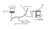
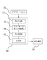
図1は、本発明が適用される印刷システムの機器構成の例を示す図である。
本発明は、ネットワーク11に接続された印刷機能を有するプリンタ12とコンピュータ14とで構成される印刷システムであっても、ネットワーク11に接続された印刷機能を有するデジタル複写機13とコンピュータ14とで構成される印刷システムであっても、適用可能である。以下、ネットワーク11に接続された印刷機能を有するプリンタ12とコンピュータ14とで構成される印刷システムを例にとって説明する。
【0019】
図2はプリンタ12とコンピュータ14とで構成される印刷システムの概略構成を示すブロック図である。コンピュータ14は、演算装置CPU21とこれに接続されるメモリ装置ROM22やメモリ装置RAM23によって構成される。そして、このコンピュータ14にはさらに、外部記憶装置24、入力装置25、表示装置26が組み込まれ、あるいは接続されている。このコンピュータ14とネットワーク11を介してプリンタ12が接続され、印刷システム20が構成されている。なおコンピュータ14とプリンタ12はネットワークではなくケーブル回線によって直接接続されていてもよい。
【0020】
この印刷システムにおいて、文書作成、表示、印刷指示などを行うアプリケーションソフトウェアは通常ROM22または外部記憶装置24からRAM23に読み込まれ、CPU21によって実行される。使用者は表示装置26に表示される情報を見ながらキーボードやポインティングデバイスなどの入力装置25によってコンピュータ14を操作し、アプリケーションソフトウェアを実行している印刷システムに印刷を指示する。
【0021】
使用者の入力操作によってアプリケーションソフトウェアが受けた印刷指示は、アプリケーションソフトウェアからの文書印刷の要求となって、文書データがプリンタドライバに渡される。CPU12によって実行されるプリンタドライバは、渡された文書データを印刷処理データに変換し、ネットワーク11を介してプリンタ12に印刷処理データを送信し、プリンタ12はこの印刷処理データに従って文書を印刷する。
【0022】
ここで、プリンタドライバは、ネットワーク回線や各種記憶媒体にて提供されうる印刷装置制御プログラムであり、コンピュータ14のメモリ装置ROM22や外部記憶装置24に格納されるものである。このプリンタドライバは、コンピュータを起動する際に、あるいは、アプリケーションソフトウェアが印刷指示を受ける際にメモリ装置ROM22や外部記憶装置24からメモリ装置RAM23に読み込まれ、印刷指示が行われたときにCPU12によって解釈実行されるプログラムである。
【0023】
[第1の実施形態]
図3は、図2に示したコンピュータ14のCPU21によって実行されるアプリケーションソフトウェア、プリンタドライバ、およびコンピュータ14に組み込まれた出力装置36(図2では図示せず)を図示するものであり、第1の実施形態の要部を説明するブロック図である。図中矢印は、データの流れを示す。
【0024】
枠で囲まれた部分は、印刷制御プログラムであるところのプリンタドライバ30である。プリンタドライバ30は、アプリケーションソフトウェア35とは独立しており、PDL作成部31と出力部32とで構成される。
【0025】
PDL作成部31では、アプリケーションソフトウェアから印刷要求される文書データを受け取り、印刷処理データとしてPDL(Page−Description Language:ページ記述言語)データを作成する。このとき、PDL作成部31では、トナーセーブモードが選択されているかどうかを判断し、選択されていれば、トナー消費が削減されるようにPDLデータを作成する。出力部32では、作成されたPDLデータを外部インターフェイスである出力装置36へ出力する。この出力装置36に接続されるネットワーク11を介して、作成されたPDLデータはプリンタ12へ出力される。
【0026】
上記プリンタドライバ30の機能を図4に示すフローチャートに沿って説明する。アプリケーションソフトから印刷要求される文書データを受け取ったプリンタドライバ30は、PDL作成処理(S1)によって、PDLデータを作成する。次に、作成したPDLデータをデータ出力(S2)する。
【0027】
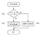
図5は、PDL作成処理S1の詳細を示すフローチャートである。PDL作成処理では、まずトナーセーブモードが選択されているか否かを判断(S11)し、選択されていれば、トナーセーブPDL作成処理を行う(S12)。また、選択されていなければ、通常PDL作成処理を行う(S13)。
【0028】
ここで、印刷システムにおけるトナーセーブモードの選択は、アプリケーションソフトウェアから文書印刷を指示する際に印刷条件としてトナーセーブモードを選択する、あるいは予めプリンタドライバに対する印刷条件として設定しておくことができる。
【0029】
図24は、GUIウィンドウシステムを用いたコンピュータにおいて、アプリケーションソフトウェアから文書の印刷指示をするときにモニター画面に表示される印刷指示ウインドウの例である。印刷指示ウインドウ40には、印刷を指示する印刷ボタン41、印刷をキャンセルするキャンセルボタン42、印刷指示先のプリンタの名称を表示あるいは印刷指示先のプリンタを選択できるプルダウンメニュー43、印刷範囲指定部44、印刷部数指定部45、印刷モード設定部46、プリンタの詳細設定を行うメニューウィンドウを呼び出す詳細設定ボタン47が描画されている。
【0030】
印刷範囲指定部44には、文書の全ページを印刷するか、現在表示されているページのみを印刷するか、あるいはページ指定を行って印刷するかを選択するためのラジオボタン44a、44b、44cが表示されており、ユーザーは、マウスやトラックボールなどのポインタ機能を有するポインティングデバイスによってポイントすることで、印刷範囲の指定を行う。ページ指定を行って印刷することを選択した場合は、表示されているテキストボックス44d、44eをポイントし、キーボードから数値を入力することでページ範囲を指定する。印刷部数指定部45には、印刷部数を指定するテキストボックス45aが表示されており、このテキストボックス45aをポイントし、数値を入力することで、印刷部数を指定する。印刷モード設定部には、トナーセーブモードを指定するためのチェックボックス46aが表示されており、このチェックボックスをポイントしてチェックマークを付けることで、トナーセーブモードを指定する。なお、このチェックボックスはトグル動作をし、ポイント動作を繰り返すことで、チェックマークが付いたり消えたりする。そして、このチェックボックス46aにチェックの付いた状態で印刷ボタンをポインタ装置を用いて押すと、トナーセーブモードを指定して文書印刷を指示することができる。
【0031】
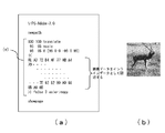
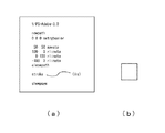
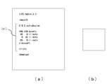
ここで、通常PDL作成処理で作成されるPDLデータの例を図6(a)、図7(a)、図8(a)、およびそれらによって印刷されるイメージを各々図6(b)、図7(b)、図8(b)に示す。なお、これ以降説明するPDLデータは、アドビシステムズ社によって制定されているポストスクリプトと呼ばれるPDL(ページ記述言語)によって表現されたデータ即ちPS(PostScript)データである。ただし、PDLデータとしてはこれに限るものではなく、PDLとしては、ヒューレット・パッカード社のプリンタに採用されているHP−PCL(Printer Control Language)や、セイコーエプソン社のプリンタに採用されているESC/Pageなど、様々なPDLであってよい。
【0032】
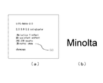
図6(a)は、フォントが「Helvetica」で、サイズが40ポイント、色が(r,g,b)=(0.0,0.0,0.8)で文字「Minolta」を座標(200,200)に表示するPSデータである。このPSデータによって印刷されるイメージは、図6(b)に示されるような、文字画像となる。
【0033】
図7(a)は、色が(r,g,b)=(0,0,0)で塗りつぶされた正方形を座標(50,50)に表示するPSデータである。このPSデータによって印刷されるイメージは、図7(b)に示されるような、塗りつぶされた正方形の図形画像となる。
【0034】
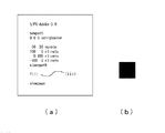
図8(a)は、イメージデータを描画するPSデータの例である。このPSデータによって印刷されるイメージは、図8(b)に示されるような、イメージ画像となる。
【0035】
図5記載のトナーセーブPDL作成処理S12の詳細を図9に示すフローチャートに従って説明する。
【0036】
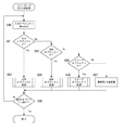
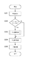
トナーセーブPDL作成処理では、まず入力オブジェクトを読み込む(S90)。次に読み込んだ入力オブジェクトが文字オブジェクトか否かを判断(S91)し、文字オブジェクトであれば、文字オブジェクト処理(S92)を行う。文字オブジェクトでなければ、次に図形オブジェクトか否かを判断(S93)する。その結果、図形オブジェクトであれば、図形オブジェクト処理(S94)を行う。S93の判断の結果図形オブジェクトでもなければ、イメージオブジェクトか否かを判断(S95)し、イメージオブジェクトであれば、イメージオブジェクト処理(S96)を行う。S95の判断の結果イメージオブジェクトでもなければ、そのオブジェクトには通常PDL作成処理(S97)を行う。これらの処理を行うたびに全PDLオブジェクト終了か否かを判定(S98)し、全PDLオブジェクト終了でなければ、S90へ戻って次の入力オブジェクトを読み込み、各ステップを繰り返し、これらの処理をすべてのオブジェクトに対し行う。全PDLオブジェクト終了であれば、トナーセーブPDL作成処理を終了する。
【0037】
上記の文字オブジェクト処理(S92)においては、その文字オブジェクトの文字サイズと所定の文字サイズとを比較することによって、輪郭線で表示するべきかどうかの判断を行う。文字サイズが大きい場合は、その文字を印刷することによる印字材料の消費が大きく、輪郭線として印刷することにより印字材料消費量の削減効果が大きく、また、その文字を判読する際にも不都合は生じない。しかしながら、文字サイズが小さい場合は、もともと印字材料の消費が少ないことと、印刷された文字を判読する際に読み難くなるため、輪郭線として印刷することの長所が失われてしまう。従って、印字材料消費量を削減することが目的とはいえ、可読性に劣らない印刷を行うためには、文字のサイズによって判断することが必要である。なお、比較の基準とする文字サイズは、35ポイントとして説明するが、これに限られるものではなく、可読性と印字材料消費削減の兼ね合いで、適当な値を設定すればよい。
【0038】
文字オブジェクト処理(S92)の詳細を、図10のフローチャートに示す。
【0039】
まず、35ポイント以上の文字サイズであるかどうかを判別する(S101)。
35ポイント以上の文字サイズであれば、通常使用されるべき「show」オペレータに換えて「false charpath stroke」オペレータを用い、文字を輪郭線で表示するようなPDL(PSデータ)を作成する(S102)。35ポイントより小さい文字サイズであれば、S103へ進み、「show」オペレータを用いた通常PDL作成処理を行う。
【0040】
このようなトナーセーブPDL作成処理における文字オプジェクト処理によって作成されたPDLデータは、図11(a)に示すようなPSデータとなり、図6(a)に示したように通常のPDLデータ(PSデータ)では、(i)「show」オペレータであるべきものが、図11(a)の(ii)「false charpath stroke」オペレータに変更されたものになっている。これによって表示されるイメージは、図11(b)のごとく、輪郭線であらわされた文字画像となる。
【0041】
ここで、「show」オペレータは、ポストスクリプトにおいて、
文字を受け取ると、現在指定されているフォントを使って、そのフォントのグリフ記述を取得して、指定された文字列のグリフをページに描画するオペレータである。一方、「charpath」オペレータは、指定された文字列の輪郭を取得するオペレータであって、直前に論理値「false」が指定されたとき、オペレータは、文字列のグリフの輪郭を現在の描画経路に追加する。これを「stroke」オペレータによって、現在の描画経路に沿って線を描画すると、指定されたフォントのグリフの輪郭のみの文字列がページに描画されることになる。
【0042】
次に上記の図形オブジェクト処理(S94)の詳細を、図12のフローチャートに示す。
【0043】
まず、入力オブジェクトが塗りつぶし図形であるかどうかを判別(S121)する。次に塗りつぶし図形であれば、S122へ進み、通常使用されるべき「fill」オペレータに換えて「Stroke」オペレータを用い、図形を輪郭線のみで表示するようにPDL(PSデータ)を作成する。塗りつぶし図形でない図形は、通常PDL作成処理(S123)を行う。
【0044】
このようなトナーセーブPDL作成処理における図形オプジェクト処理によって作成されたPDLデータは、図13(a)に示すようなPSデータとなり、図7(a)に示した通常のPDLデータ(PSデータ)において、(iii)「fill」オペレータであったものが、(iv)「stroke」オペレータに変更されたものになっている。これによって表示されるイメージは、図13(b)のごとく、輪郭線であらわされた図形画像となる。
【0045】
ここで、「fill」オペレータは、ポストスクリプトにおいて、現在の描画経路の内側を現在指定されている色で塗りつぶすよう指示するオペレータである。一方、「stroke」オペレータは前述のごとく、現在の描画経路に沿って線を描画するよう指示するオペレータである。
【0046】
上記のイメージオブジェクト処理(S95)の詳細を、図14のフローチャートに示す。
【0047】
S141においては、イメージオブジェクトの描画位置、描画領域サイズを判定し、イメージオブジェクトの描画領域サイズに応じた大きさの矩形を黒色の輪郭線のみで描画するように、即ち、イメージオブジェクトを輪郭線図形オブジェクトに変更したPDL(PSデータ)を作成する。
【0048】
このようなトナーセーブPDL作成処理におけるイメージオブジェクト処理によって作成されたPDLデータは、図15(a)に示すようなPSデータとなる。図8(a)に示した通常のPDLデータ(PSデータ)において、イメージオブジェクト指定されていた(図中(v)の記述)ものが、同じ大きさの黒い輪郭線で描画される矩形の図形を描く(図中(vi)の記述)ように変更されたものになっている。これによって表示されるイメージは、図15(b)のごとく、輪郭線であらわされた図形画像となる。
【0049】
ここで、図8(a)中の(v)部分に記載されたポストスクリプトの記述に関して説明する。「100 100 translate」は、イメージ画像を描画する場所を「水平方向に100単位、垂直方向に100単位」に指定する。「95 95 scale」は、イメージ画像のスケールの拡大縮小を指定する。イメージ画像は、もともと「水平方向に1単位、垂直方向に1単位」の単位正方形として扱われるので、これを各々95倍して描画する。次の行の、「95 95 8」とあるのは、イメージ画像データソースのサイズであって、高さ95ピクセル、横幅95ピクセルで、各8ビットのRGB値でであることを示す。続く「[95 0 0 −95 0 95]」は、単位正方形に対するデータ配置を指定する。中括弧内には、画像データがRGB各色8ビットの16進データで記述されている。
「colorimage」は、カラーイメージを描画するオペレータである。「colorimage」の前に指定された「false」は、単一のデータソースからイメージを取得することを指定するオペランドであり、続く「3」は、色成分の数を指定するオペランドである。以上の記述によって、95×95ピクセルのRGB各色8ビットのカラーイメージが、高さ95単位、幅95単位の大きさで、描画される。
【0050】
一方、図15(a)中の(vi)部分に記載されたポストスクリプトの記述においては、「0 0 0 setrgbcolor」によって、現在の描画色が黒に指定される。「100 100 moveto」で、現在の描画ポイントが、「水平方向に100単位、垂直方向に100単位」の場所に置かれる。その場所から「95 0 rlineto」、「「0 95 rlineto」」、「−95 0 rlineto」のオペレータによって、現在の描画ポイントから指定された相対位置へ向かって直線が描画経路として設定され、「closepath」で、現在の描画経路が閉じられる。最後にstrokeによって、描画経路に沿って線が描かれる。
【0051】
従って、図8(a)中の(v)部分の記述であるべきものを図15(a)中の(vi)部分の記述に変更すると、高さ95単位、幅95単位で描かれるイメージ画像であるべきものが、その描画領域と同じ大きさの輪郭線の矩形として描画される。
【0052】
なお、この図8、図15に示した例では、カラーイメージデータを対象とした場合を示したが、モノクロイメージデータの場合も同様の処理を行う。
【0053】
以上説明したようなプリンタドライバ30で作成され出力されるPDLデータは、トナーセーブモードが指定されている場合に、以下のようなものになっている。即ち、トナー材料を多く消費する大きな文字は、輪郭線で出力するようなPDLへ変更し、また、塗りつぶし図形は輪郭線のみで出力するようなPDLへ変更され、あるいは、イメージデータはそのイメージ領域の大きさを表現する輪郭線画像として出力するようなPDLへ変更されたものになっている。このPDLデータをプリンタ12が受け取って、そのPDLデータをプリンタ12が解釈実行し、紙などへの媒体への印刷を行うと、トナー材料を多く消費する大きな文字は、輪郭線で表され、また、塗りつぶし図形は輪郭線のみの図形に変換され、あるいは、イメージデータは、そのイメージの大きさを表現する輪郭線画像として印刷される。その結果、このプリンタドライバ30を用いた印刷システムにおいては、トナーセーブモードを選択して印刷を実行すると、トナーの消費量を削減し、トナーを節約することになる。
【0054】
また、本第1の実施形態のように、コンピュータ側で実行されるドライバプログラムにてPDLを変更する場合、同じPDL(ページ記述言語)に対応したプリンタであれば、どのプリンタに送信しても同じようにトナーを節約することができる。
【0055】
[第2の実施形態]
図18は、図2に示したコンピュータ14のCPU21によって実行されるアプリケーションソフトウェア、プリンタドライバ、およびコンピュータ14に組み込まれた出力装置36(図2では図示せず)を図示するものであり、第2の実施形態の要部を説明するブロック図である。図中矢印は、データの流れを示す。
【0056】
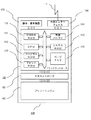
枠で囲まれた部分は、印刷制御プログラムであるところのプリンタドライバ50である。プリンタドライバ50は、アプリケーションソフトウェア35とは独立しており、PDL作成部51とトナーセーブモード判断部53、PDL変更部54、出力部52とで構成される。
【0057】
PDL作成部51では、アプリケーションソフトウェアから印刷要求される文書データを受け取り、印刷処理データとして通常のPDLデータを作成する。
【0058】
トナーセーブモード判断部53では、トナーセーブモードが設定されているか否かを判断する。
【0059】
PDL変更部54では、トナーセーブモード判断部53で判断された結果に基づき、トナーセーブモードが選択されていれば、トナー消費が削減されるようにPDL作成部51で作成されたPDLデータを変更する。出力部52では、作成されたPDLデータを外部インターフェイスである出力装置36へ出力する。この出力装置36に接続されるネットワーク11を介して、作成されたPDLデータはプリンタ12へ出力される。
【0060】
上記プリンタドライバ50の機能を図19に示すフローチャートに沿って説明する。まずアプリケーションソフトから印刷要求される文書データを受け取ったプリンタドライバ50は、PDL作成処理(S201)によって、通常のPDLデータを作成する。次に、トナーセーブモードが指定されているか否かを判断(S202)する。ここで、印刷システムにおけるトナーセーブモードの選択は、第1の実施形態と同様に行われる。トナーセーブモードが指定されていると判断されたら、S201において作成したPDLデータをPDL変更部54においてPDL変更処理(S203)を行い、通常のPDLデータをトナー消費が削減されるようなPDLデータへ変更する。S202において、トナーセーブモードが指定されていないと判断されたらPDL変更処理は行わない。以上のステップを経て作成されあるいは変更されたPDLデータは、続いて、データ出力(S204)される。
【0061】
図20は、上記PDL変更処理S203の詳細を示すフローチャートである。PDL変更処理では、まずPDL作成処理(S201)で作成されたPDLデータからPDLオブジェクトを読み込む(S211)。
【0062】
次に、読み込んだPDLオブジェクトが文字オブジェクトか否かを判断(S212)し、文字オブジェクトであれば、文字オブジェクト処理(S213)を行う。文字オブジェクトでなければ、次に図形オブジェクトか否かを判断(S214)する。その結果、図形オブジェクトであれば、図形オブジェクト処理(S215)を行う。S214の判断の結果図形オブジェクトでもなければ、イメージオブジェクトか否かを判断(S216)し、イメージオブジェクトであれば、イメージオブジェクト処理(S217)を行う。S216の判断の結果イメージオブジェクトでもなければ、そのオブジェクトには処理を行わない。以上の全ての処理を行うたびに全PDLオブジェクト終了か否かを判定(S218)し、全PDLオブジェクト終了でなければ、S211へ戻って次の入力オブジェクトを読み込み、各ステップを繰り返し、これらの処理をすべてのオブジェクトに対し行う。全PDLオブジェクト終了であれば、PDL変更処理を終了する。
【0063】
以下、図20に示すフローチャート中の文字オブジェクト処理(S213)、図形オブジェクト処理(S215)、イメージオブジェクト処理(S217)の詳細を説明する。なお、ここで、図19のフローチャートのPDL作成処理(S201)によって作成される通常のPDLデータは、第1実施の形態と同様に、PSデータであるものとする。その例として、PSデータに含まれる文字オブジェクトは、図6(a)に示すスクリプトで表されたものであり、図形オブジェクトは図7(a)に示すスクリプトで表されたものであり、イメージオブジェクトは図8(a)に示すスクリプトで表されたPSデータであるとする。また、各々の通常のPSデータによって印刷される画像イメージは、各々図6(b)、図7(b)、図8(b)となる。
【0064】
上記の文字オブジェクト処理(S213)の詳細を、図21のフローチャートに示す。まず、35ポイント以上の文字サイズであるかどうかを判別する(S221)。35ポイント以上の文字サイズであれば、「show」オペレータを「false charpath stroke」オペレータに置き換えて、文字を輪郭線で表示するようにPDL(PSデータ)を変更する(S222)。35ポイントより小さい文字サイズであれば、S222へ進まず、処理を終了する。
【0065】
このようなPDL変更処理における文字オプジェクト処理によって変更されたPDLデータは、図11(a)に示すようなPSデータとなり、図6(a)に示した通常のPDLデータ(PSデータ)において、(i)「show」オペレータであったものが、(ii)「false charpath stroke」オペレータに変更されたものになっている。これによって印刷されるイメージは、図11(b)のごとく、輪郭線であらわされた文字画像となる。
【0066】
次に上記の図形オブジェクト処理(S215)の詳細を、図22のフローチャートに示す。
【0067】
まず、入力オブジェクトが塗りつぶし図形であるかどうかを判別(S231)する。次に塗りつぶし図形であれば、S122へ進み「fill」オペレータに換えて「Stroke」オペレータを用い、図形を輪郭線のみで表示するようにPDL(PSデータ)を変更する。塗りつぶし図形でない図形であれば、S232へ進まず、処理を終了する。
【0068】
このようなPDL変更処理における図形オプジェクト処理によって変更されたPDLデータは、図13(a)に示すようなPSデータとなり、図7(a)に示した通常のPDLデータ(PSデータ)において、(iii)「fill」オペレータであったものが、(iv)「stroke」オペレータに変更されたものになっている。これによって印刷されるイメージは、図13(b)のごとく、輪郭線であらわされた図形画像となる。
【0069】
上記のイメージオブジェクト処理(S217)の詳細を、図23のフローチャートに示す。
【0070】
S241においては、イメージオブジェクトの描画位置、描画領域サイズを判定し、イメージオブジェクトの描画領域サイズに応じた大きさの矩形を黒色の輪郭線のみで描画するように、PDL(PSデータ)を変更する。即ち、イメージオブジェクトを輪郭線図形オブジェクトに変更するようにPDL(PSデータ)を変更する。
【0071】
このようなPDL変更処理におけるイメージオプジェクト処理によって変更されたPDLデータは、図15(a)に示すようなPSデータとなり、図8(a)に示した通常のPDLデータ(PSデータ)において、イメージオブジェクト指定されていた(図中(v)の記述)ものが、同じ大きさの黒い輪郭線で描画される矩形の図形を描く(図中(vi)の記述)ように変更されたものになっている。これによって印刷されるイメージは、図15(b)のごとく、輪郭線であらわされた図形画像となる。
【0072】
なお、この図8、図15に示した例では、カラーイメージデータを対象とした場合を示したが、モノクロイメージデータの場合も同様の処理を行う。
【0073】
以上説明したようなプリンタドライバ50で作成され出力されるPDLデータは、トナーセーブモードが指定されている場合は、トナー材料を多く消費する大きな文字は、輪郭線で出力するようなPDLへ変更し、また、塗りつぶし図形は輪郭線のみで出力するようなPDLデータへ変更されたものになっている。このPDLデータを印刷装置が受け取って、そのPDLデータを印刷装置が解釈実行し、紙などへの媒体への印刷を行うと、トナー材料を多く消費する大きな文字は、輪郭線で表され、また、塗りつぶし図形は輪郭線のみの図形に変換され、あるいは、イメージデータは、そのイメージの大きさを表現する輪郭線画像として印刷される。その結果、このプリンタドライバ30を用いた印刷システムにおいては、トナーセーブモードを選択して印刷を実行すると、トナーの消費量を削減し、トナーを節約することになる。
【0074】
また、本第2の実施形態のように、コンピュータ側で実行されるドライバプログラムにてPDLを変更する場合、同じPDL(ページ記述言語)に対応したプリンタであれば、どのプリンタに送信しても同じようにトナーを節約することができる。
【0075】
[第3の実施形態]
まず、第3の実施形態で印刷装置として使用されるプリンタを図25のブロック図で説明する。
【0076】
プリンタ100は、プリンタコントローラ101、メカコントローラ102、プリントエンジン103、外部インターフェイス104、操作・表示装置120を具える。
【0077】
プリンタコントローラ101は、CPU111、プログラムROM112、フォントROM113、受信バッファ114、システムRAM115、ページメモリ116、CMOSRAM118を含み、これらはシステムバスによって接続されている。
【0078】
CPU111は、プログラムROM112に格納されたプログラムを実行し、そのプログラムに従って、操作・表示装置120による指示と、CMOSRAM118に記憶されている設定情報と、受信した印刷処理データとに従って、プリンタ全体を制御する。
【0079】
プログラムROM112は、CPU111によって実行されるプリンタ制御プログラムを格納する読み出し専用の半導体メモリである。この読み出し専用の半導体メモリとしては、不揮発性のメモリ装置が用いられる。
【0080】
フォントROM113は、印刷に用いる文字の形状データ即ちフォントデータを格納する。
【0081】
受信バッファ114は、外部から受信した印刷処理データを一時的に格納するランダムアクセスメモリである。
【0082】
システムRAMは、CPU111の演算処理のデータの格納や、ダウンロードしたフォントを格納するのに用いられるランダムアクセスメモリである。
【0083】
ページメモリ116は、印刷処理データの印刷対象がラスタライズされたビットマップデータを格納するランダムアクセスメモリである。
【0084】
CMOSRAM118は、コンピュータ機器から指定されたり操作・表示装置からの操作で設定されたりするプリンタの設定情報や、自己診断結果情報などを記憶しておく半導体メモリであって、プリンタ100の電源が切られてもその内容が消えないように、バッテリバックアップされている。
【0085】
メカコントローラ112は、プリントエンジンの機械的な制御を行うコントローラであり、プリンタコントローラ101およびプリントエンジン103に接続されている。
【0086】
プリントエンジン103は、印字材料としてトナーを用い、帯電装置、レーザーやLEDなどの露光装置、感光体ドラム、現像装置、転写装置、給紙搬送装置、定着装置などからなる電子写真作像システムからなる。プリンタコントローラから送られるラスタライズされたビットマップデータに従って、感光体ドラム上に静電気潜像を形成し、現像装置のトナーを用いて現像し、給紙搬送装置で送られる紙に転写装置を用いてトナー画像を転写した後、定着装置にて紙上の転写されたトナー画像を定着することで、印刷を行う。
【0087】
なお、プリントエンジン103は、インクを紙に飛翔させて印刷を行うインクジェットシステムからなるものでもよいし、ワックスインクをサーマルヘッドで溶融して紙に印字する熱転写システムからなるものなどでもよい。
【0088】
外部インターフェイス104は、ネットワーク11に接続され、ネットワークに接続されたコンピュータ機器からの印刷処理データをネットワークを介して受け取り、プリンタコントローラ101の受信バッファ114へ印刷処理データを格納する。上記ネットワークに換えて、コンピュータとプリンタ100がケーブル回線で直接接続される場合も同様である。
【0089】
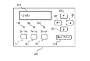
操作・表示装置120は、図26に示すような操作パネル120である。操作パネルには、ボタン121、122、123、メニューキー124、カーソルキー125、126、127、128、および液晶表示装置からなるメッセージディスプレイ129が備わっている。又、オンライン表示、印刷中、エラー警告を行うLEDランプ131、132、133を具える。
【0090】
ユーザーは、メッセージディスプレイ129の表示に従って、また、各LEDランプの点灯状態を判断して、それぞれのボタンやキーを操作することで、プリンタ100に対する指示や設定を行う。プリンタ100の各種設定を行う際は、メニューキーを押下することでメッセージディスプレイに表示されるメニューを各カーソルキーを操作してメニューの項目や設定値を選択する。選択されたメニューの項目や設定値は、メニューキーの押下で確定することができる。
【0091】
第3の実施形態では上述したプリンタ100のプログラムROM112に格納されたプリンタ制御プログラムに、PDL変更機能が備わる。この第3の実施形態の主要部を図27のブロック図に示す。
【0092】
枠で囲まれた部分は、プログラムROM112に格納され、CPU111によって読み込まれ実行されるプリンタ制御プログラム90である。プリンタ制御プログラム90は、PDL読込み部91とトナーセーブモード判断部92、PDL変更部93、PDL解析処理部94とを含んで構成される。
【0093】
プリンタ100が外部インターフェイス104を通じてネットワーク接続されたコンピュータから受け取り、受信バッファ114へ格納する印刷処理データは、ページ記述言語で記述されたPDLデータである。
【0094】
PDL読込み部では、上述の受信バッファ114に一時的に格納されたPDLデータを順次読み込む。トナーセーブモード判断部53では、印刷要求を行ったコンピュータからの印刷時の指示によってトナーセーブモードが設定されているか、あるいは、上記操作パネルの操作によって、プリンタ100に対し、トナーセーブモードが設定されているか否かを判断する。
【0095】
PDL変更部93では、トナーセーブモード判断部92で判断された結果に基づき、トナーセーブモードが選択されていれば、トナー消費が削減されるようにPDL読込み部91で読み込んだPDLデータを変更する。PDL解析処理部94は、PDLデータに従って、PDLデータに含まれる文字オブジェクトや図形オブジェクトあるいはイメージオブジェクト等をラスタライズし、ページメモリ116に格納する。また、PDL解析処理部94は、PDLデータに含まれるプリンタに対するコマンド要求を解釈して、メカコントローラ102に指示を送り、プリントエンジン103を動作させる。このようにして、ページメモリに蓄えられたビットマップデータをプリントエンジン103に送ることで文書データの印刷が実行される。
【0096】
上記プリンタ制御プログラム90の機能を図28に示すフローチャートに沿って説明する。
【0097】
上述の受信バッファ114に一時的に格納されたPDLデータを順次読み込む(S301)。次に、トナーセーブモードが指定されているか否かを判断(S302)する。トナーセーブモードが指定されていると判断されたら、PDLデータをPDL変更部93においてPDL変更処理(S303)を行い、通常のPDLデータをトナー消費が削減されるようなPDLデータへ変更する。S303において、トナーセーブモードが指定されていないと判断されたらPDL変更処理は行わない。以上のステップを経て作成されあるいは変更されたPDLデータは、続いて、PDL解析処理(S204)され、PDLデータに従って、印刷処理(S305)される。
【0098】
上記PDL変更処理303の詳細は、上述の図20のフローチャートに示すPDL変更処理と同一である。また、図29に示すように、逐次読み込んだPDLオブジェクトを変換処理し、変換したPDLデータをPDL解析処理へ流すものであってもよい。
【0099】
図29は、上記PDL変更処理S303の一例の詳細を示すフローチャートである。まずPDLデータからPDLオブジェクトを読み込む(S311)。
【0100】
次に、読み込んだPDLオブジェクトが文字オブジェクトか否かを判断(S312)し、文字オブジェクトであれば、文字オブジェクト処理(S313)を行う。文字オブジェクトでなければ、次に図形オブジェクトか否かを判断(S314)する。その結果、図形オブジェクトであれば、図形オブジェクト処理(S315)を行う。S314の判断の結果図形オブジェクトでもなければ、イメージオブジェクトか否かを判断(S316)し、イメージオブジェクトであれば、イメージオブジェクト処理(S317)を行う。S316の判断の結果イメージオブジェクトでもなければ、そのオブジェクトには処理を行わなずにこのPDL変更処理を終了する。
【0101】
、図29のフローチャートにおける、各オブジェクト処理(S313、S315、S317)の詳細は、第2の実施形態と同じであり、文字オブジェクト処理(S313)は図21のフローチャート、図形オブジェクト処理(S315)は図22のフローチャート、イメージオブジェクト処理(S317)は図23のフローチャートで示されるものと同一である。
【0102】
以上説明したようなプリンタ制御プログラム90を実行するプリンタ100においては、コンピュータ14から受信したPDLデータを解釈実行する前に、トナーセーブモードが指定されている場合は、トナー材料を多く消費する大きな文字は、輪郭線で出力するようなPDLへ変更し、また、塗りつぶし図形は輪郭線のみで出力するようなPDLデータへ変更する。この変更されたPDLデータを後段のPDL解析処理部で解釈実行し、紙などへの媒体への印刷を行うと、トナー材料を多く消費する大きな文字は、輪郭線で表され、また、塗りつぶし図形は輪郭線のみの図形に変換され、あるいは、イメージデータは、そのイメージの大きさを表現する輪郭線画像として印刷される。その結果、プリンタ制御プログラム90を実行するプリンタ100を用いた印刷システムにおいては、トナーセーブモードを選択して印刷を実行すると、トナーの消費量を効果的に削減し、トナーを節約することができる。
[第4の実施形態]
上述の第2の実施形態では、プリンタドライバ内部で、トナーセーブモードが指定されているか否かの判断を行い、PDL変更処理をおこなっているが、この機能を、独立した別プログラムとして構成し、プリンタドライバから出力装置36へ送信されるPDLデータを横取りして受け取ってPDL変更処理を行うフィルタープログラムとして作用するものとしてもよい。 その形態を図30のブロック図に示す。
【0103】
図30は、図2に示したコンピュータ14のCPU21によって実行されるアプリケーションソフトウェア、プリンタドライバ、フィルタープログラム、およびコンピュータ14に組み込まれた出力装置36(図2では図示せず)を図示するものであり、第4の実施形態の要部を説明するブロック図である。図中矢印は、データの流れを示す。
【0104】
図中85は、通常のPDLを出力するプリンタドライバである。プリンタドライバ85は、アプリケーションソフトウェア35とは独立しており、PDL作成部86と出力部87とで構成される。
【0105】
PDL作成部86では、アプリケーションソフトウェアから印刷要求される文書データを受け取り、印刷処理データとして通常のPDLデータを作成する。
【0106】
出力部87では、作成されたPDLデータを、通常は外部インターフェイスである出力装置36へ出力する。
【0107】
図中80は、フィルタープログラムであって、上記プリンタドライバ85とは独立したプログラムであり、トナーセーブモード判断部81と、PDL変更部82、および出力部83とで構成される。フィルタープログラム80は、上記プリンタドライバ85がPDLデータを出力すると呼び出されて実行される。
【0108】
フィルタープログラム80のトナーセーブモード判断部81では、トナーセーブモードが設定されているか否かを判断する。トナーセーブモードが設定されていると判断すると、PDL変更部82では、上記プリンタドライバ83の出力するPDLデータを横取りして逐次読み込んで、トナー消費が削減されるようにPDLデータを変更するPDL変更処理をおこなう。出力部83では、PDL変更部82で変更処理されたPDLデータを出力装置36へ送信する。
【0109】
コンピュータ14の外部インターフェイスである出力装置36へ送信されたPDLデータは、出力装置36に接続されたネットワークあるいはケーブル回線を介してプリンタへ送信され、プリンタにおいて紙へ印刷される。
【0110】
PDL変更部82におけるPDL変更処理は、第2の実施形態において図20を用いて説明したPDL変更処理あるいは上述の第3の実施形態において図29を用いて説明したPDL変更処理と同様に行われる。
【0111】
以上説明したようなフィルタープログラム80で出力されるPDLデータは、トナーセーブモードが指定されている場合は、トナー材料を多く消費する大きな文字は、輪郭線で出力するようなPDLへ変更し、また、塗りつぶし図形は輪郭線のみで出力するようなPDLデータへ変更されたものになっている。このPDLデータを印刷装置が受け取って、そのPDLデータを印刷装置が解釈実行し、紙などへの媒体への印刷を行うと、トナー材料を多く消費する大きな文字は、輪郭線で表され、また、塗りつぶし図形は輪郭線のみの図形に変換され、あるいは、イメージデータは、そのイメージの大きさを表現する輪郭線画像として印刷される。その結果、このプリンタドライバ30を用いた印刷システムにおいては、トナーセーブモードを選択して印刷を実行すると、トナーの消費量を削減し、トナーを節約することになる。
【0112】
また、本第4の実施形態のように、コンピュータ側で実行されるフィルタープログラムにてPDLを変更する場合、同じPDL(ページ記述言語)に対応したプリンタであれば、どのプリンタに送信しても同じようにトナーを節約することができる。
[他の実施の形態]
第4の実施形態におけるフィルタープログラムのような機能を、プリンタへの印刷データを一時的に蓄えて、順次プリンタへ送信するスプーラプログラムの機能として実装してもよい。 また、以上の説明では、コンピュータと印刷装置とそれらを接続するネットワークあるいは、ケーブル回線からなる印刷システムとして説明してきたが、コンピュータ機器と印刷装置の間のネットワークまたはケーブル回線にプリントサーバを介在させた形態でも良い。さらに、介在するプリントサーバに、プログラムを格納する不揮発性メモリ装置と、プログラムを実行するCPU演算装置と、が含まれる場合、不揮発性メモリ装置に格納されるプログラムとしてそのような機能を持たせ、プリントサーバのCPU演算装置にて実行させるようにしても良い。
【0113】
さらに、以上の第1から第4の実施形態では、トナーセーブモードが指定されているか否かの判断を行い、それに応じてPDL変更処理を行う機能を、ソフトウェアプログラムとして実装する形態を主に説明したが、そのような機能を電気回路化してハードウェアとして実装するものであってもよい。
【0114】
以上説明した実施の形態におけるPDL変更処理では、文字オブジェクト処理において、輪郭線で表示するか否かの判定を文字の大きさで判定したが、これに限定するものではない。文字の大きさと文字の形状即ちフォントの種類と両方を併せて輪郭線文字で表示するのか否かを判断しても良いし、また、フォントの種類によって判断基準とする所定の文字サイズの大きさを変更するようにしても良い。これによって、多様なフォントを用いる文書において、より判読しやすくかつ効果的に印字材料の消費量を削減することが可能となる。
【0115】
また、以上説明した文字や図形あるいはイメージオブジェクト処理では、各オブジェクトを輪郭線のみで表示することとしたが、これに限定するものではない。例えば、輪郭線の中にハッチング処理を施すことにしてもよいし、輪郭線の中を網点で塗りつぶすようにしても効果は劣るものの、トナー消費を削減することができる。
【0116】
また、図形オブジェクトとしては、塗りつぶし図形に限らず、線幅により、幅の大きな線分は輪郭線のみで再現するようにしたりすることで、トナー消費量を節約することも可能である。図13は、10ポイント幅の線分を、輪郭線のみで表現した例である。さらに、図14に示すように中間調を有するグラディエーション画像部を輪郭で再現することも可能である。
【0117】
また、イメージオブジェクトに関しては、輪郭線であらわした画像領域の中に、小さい文字や、濃度の薄い文字で、「イメージ画像」などの文字を印字して、識別を容易にするように工夫しても良い。
【0118】
なお、以上説明した実施の形態には、請求項に掲げるものほか、以下に掲げるような発明も含む。
【0119】
[第6の発明]
所定のモードが指定されているか否かを判別するステップと、
該所定のモードが指定されている場合に、印刷処理すべき文書データに含まれる文字オブジェクトの文字サイズおよび文字の形状の種類を判定するステップと、
判定された文字の形状の種類によって、所定の文字サイズを決定するステップと、
判定された文字サイズが所定の文字サイズ以上である場合に
文字オブジェクトが輪郭線として印刷されるべく印刷処理データを変更するステップと、
を含む、印刷装置制御プログラム。
【0120】
[第7の発明]
請求項1乃至4あるいは、上記第6の発明において、所定のモードが、印字材料節約モードであることを特長する印刷装置制御プログラム。
【0121】
[第8の発明]
プログラムを格納する不揮発性メモリ装置と、
プログラムを実行するCPU演算装置と、
を含み、
該不揮発性メモリ装置に、上記第6乃至第7の発明に記載の印刷装置制御プログラムが格納され、該CPU演算装置によって実行されること
を特徴とする印刷装置。
【0122】
[第9の発明]
請求項5あるいは第8の発明に記載の印刷装置において、
さらに、印字材料節約モードを指定するモード指定手段を有することを特徴とする印刷装置。
【0123】
[第10の発明]
プログラムを格納する不揮発性メモリ装置と、
プログラムを実行するCPU演算装置と、
を含み、
該不揮発性メモリ装置に、請求項1乃至4または、上記第6または第7の発明に記載の印刷装置制御プログラムが格納され、該CPU演算装置によって実行されること
を特徴とするプリントサーバ装置。
【0124】
[第11の発明]
印字材料節約モードを指定するモード指定手段と、
印字材料節約モードが指定されているか否かを判別するモード判定手段と、
印字材料節約モードが指定されている場合に、印刷処理すべき文書データに含まれる 文字オブジェクト の文字サイズを判定する文字サイズ判定手段と、
判定された文字サイズを所定の文字サイズと比較する手段と、
判定された文字サイズが所定の文字サイズ以上である場合に
文字オブジェクトが輪郭線として印刷されるべく印刷処理データを変更する手段と、
を有する事を特徴とする印刷システム。
【0125】
[第12の発明]
第11の発明において、さらに、
文書データに含まれる文字オブジェクトの文字の形状の種類を判定する手段と、判定された文字の形状の種類によって、所定の文字サイズを決定する手段と、を含む、印刷システム。
【0126】
[第13の発明]
印字材料節約モードを指定するモード指定手段と、
印字材料節約モードが指定されているか否かを判別するモード判定手段と、
印字材料節約モードが指定されている場合に、印刷処理すべき文書データに含まれる図形オブジェクトが塗りつぶし図形であるか否かを判定する手段と、
判定された図形オブジェクトが塗りつぶし図形である場合に
図形オブジェクトが輪郭線として印刷されるべく印刷処理データを変更する手段と、
を有する事を特徴とする印刷システム。
【0127】
[第14の発明]
印字材料節約モードを指定するモード指定手段と、
印字材料節約モードが指定されているか否かを判別するモード判定手段と、
トナー節約モードを指定するモード指定手段と、
トナー節約モードが指定されているか否かを判別するモード判定手段と、
印字材料節約モードが指定されている場合に、印刷処理すべき文書データに含まれるイメージオブジェクトがイメージ領域の輪郭線として印刷されるべく印刷処理データを変更する手段と、
を有する事を特徴とする印刷システム。
【0128】
【発明の効果】
以上説明したように、本発明の請求項1〜4記載の印刷装置制御プログラム、あるいは、請求項5記載の印刷装置によれば、所定のモードあるいは印字材料節約モードが指定されているか否かを判別し、印刷処理すべき文書データに含まれる所定のサイズ以上の文字オブジェクトや塗りつぶし図形オブジェクトあるいはイメージオブジェクトを、各々輪郭線として印刷されるべく印刷処理データを変更することで、文書の判読性を損なうことなく、印刷装置によって使用されるトナーの使用量を効果的に節約するすることができる。
【図面の簡単な説明】
【図1】本発明が適用される印刷システムの機器構成の例を示す図である。
【図2】本発明が適用される印刷システムの概略構成を示すブロック図である。
【図3】第1の実施形態の主要部を示すブロック図である。
【図4】第1の実施形態におけるプリンタドライバの機能を説明するフローチャートである。
【図5】第1の実施形態におけるPDL作成処理の機能を説明するフローチャートである。
【図6】(a)は文字オブジェクトを表すPDLデータの例であり、(b)はそのPDLデータに従って印刷される画像である。
【図7】(a)は塗りつぶし図形オブジェクトを表すPDLデータの例であり、(b)はそのPDLデータに従って印刷される画像である。
【図8】(a)はイメージオブジェクトを表すPDLデータの例であり、(b)はそのPDLデータに従って印刷される画像である。
【図9】第1の実施形態におけるトナーセーブPDL作成処理の機能を説明するフローチャートである。
【図10】第1の実施形態における文字オブジェクト処理を説明するフローチャートである。
【図11】(a)はトナー節約のために文字オブジェクトを輪郭線で表すPDLデータの例であり、(b)はそのPDLデータに従って印刷される画像である。
【図12】第1の実施形態における図形オブジェクト処理を説明するフローチャートである。
【図13】(a)はトナー節約のために輪郭線で図形オブジェクトを表すPDLデータの例であり、(b)はそのPDLデータに従って印刷される画像である。
【図14】第1の実施形態におけるイメージオブジェクト処理を説明するフローチャートである。
【図15】(a)はトナー節約のために輪郭線図形でイメージデータ領域を表すPDLデータの例であり、(b)はそのPDLデータに従って印刷される画像である。
【図16】本発明に係る線分画像を輪郭線図形画像に変更する例を示す画像である。
【図17】本発明に係るグラデーション画像を輪郭線図形に変更する例を示す画像である。
【図18】第2の実施形態の主要部を示すブロック図である。
【図19】第2の実施形態におけるプリンタドライバの機能を説明するフローチャートである。
【図20】第2の実施形態におけるPDL作成処理の機能を説明するフローチャートである。
【図21】第2の実施形態における文字オブジェクト処理を説明するフローチャートである。
【図22】第2の実施形態における図形オブジェクト処理を説明するフローチャートである。
【図23】第2の実施形態におけるイメージオブジェクト処理を説明するフローチャートである。
【図24】本発明が適用される印刷システムにおいて、トナー節約モードを指定することのできる印刷の指示を行うプログラムの画面表示の例を示す図である。
【図25】本発明が適用される印刷システムにおいて用いられるプリンタ装置の概略を示すブロック図である。
【図26】本発明が適用される印刷システムにおいて用いられるプリンタ装置の操作・表示装置の例を示す図である。
【図27】第3の実施形態の主要部を示すブロック図である。
【図28】第3の実施形態におけるプリンタ制御プログラムの機能を説明するフローチャートである。
【図29】第3の実施形態におけるプリンタ制御プログラムのPDL変更処理を説明するフローチャートである。
【図30】第4の実施形態の主要部を示すブロック図である。
【符号の説明】
11 ネットワーク
12 プリンタ
13 デジタル複写機
14 コンピュータ
20 印刷システム
21 演算装置CPU
22 メモリ装置ROM
23 メモリ装置RAM
24 外部記憶装置
25 入力装置
26 表示装置
30 プリンタドライバ
31 PDL作成部
32 出力部
35 アプリケーション
36 出力装置
40 印刷指示ウインドウ
41 印刷ボタン
42 キャンセルボタン
43 プルダウンメニュー
44 印刷範囲指定部
44a、44b、44c ラジオボタン
44d、44e テキストボックス
45 印刷部数指定部
45a テキストボックス
46 印刷モード設定部
46a チェックボックス
47 詳細設定ボタン
50 プリンタドライバ
51 PDL作成部
52 出力部
53 トナーセーブモード判断部
54 PDL変更部
80 フィルタープログラム
81 トナーセーブモード判断部
82 PDL変更部
83 出力部
85 プリンタドライバ
86 PDL作成部
87 出力部
90 プリンタ制御プログラム
91 PDL読込み部
92 トナーセーブモード判断部
93 PDL変更部
94 PDL解析処理部94
100 プリンタ
101 プリンタコントローラ
102 メカコントローラ
103 プリントエンジン
104 外部インターフェイス
111 CPU
112 プログラムROM
113 フォントROM
114 受信バッファ
115 システムRAM
116 ページメモリ
118 CMOSRAM
120 操作・表示装置
121、122、123 ボタン
124 メニューキー
125、126、127、128 カーソルキー
129 メッセージディスプレイ
131、132、133 LEDランプ[0001]
TECHNICAL FIELD OF THE INVENTION
The present invention relates to a printing system that prints print data from a computer device such as a personal computer with a printer device such as a laser printer, a digital copier, an ink jet printer, or a thermal transfer printer. The present invention relates to a printing material saving technique in a saving mode for saving and printing.
[0002]
[Prior art]
In a printing system that transmits print processing data from a computer device or the like to a printer device such as a laser printer or a digital copier, and prints a document on a printer device as a printing device in accordance with the print processing data, a draft printing or a draft mode is conventionally used. For example, when rasterizing print data, thinning out the dots to reduce the print quality instead of reducing the print quality, or in a toner save mode, for example, lowering the print density and saving printing material such as toner Things have been done.
[0003]
For example, a conventional printing device analyzes the printing information sent from the host computer device on the printing device side, determines the character thickness from the character type and size, and prints with the density corresponding to the toner. Techniques for performing saves are known. (For example, refer to
Further, as a technique for saving printing materials, a technique is also known in which a printer control device forcibly prints only the outline of a character in a toner saving mode. (For example, see
Further, as a technique for saving printing materials, there is also known a technique in which a filled area of image data is replaced with thinned data in a toner saving mode, and an outline and a thinned area image after thinning are synthesized and printed. (For example, see Patent Document 3)
[Patent Document 1]
JP-A-10-315542
[Patent Document 2]
JP-A-5-309871
[Patent Document 3]
JP-A-9-27041
[0004]
[Problems to be solved by the invention]
In the above-described conventional technology, it is possible to print with reduced character density or to print only the outline of the character in order to save printing material, but graphics such as circles and squares are not considered and include graphics. In some cases, this was not enough to save printing material when printing a document. Although the density of the halftone image data is also reduced, printing is not always sufficient to save printing material.
[0005]
Further, the toner save described in
[0006]
According to the technique described in
[0007]
According to the technology described in
[0008]
Therefore, an object of the present invention is to provide a technique for more effectively saving printing materials without increasing hardware costs. It is still another object of the present invention to provide a technique capable of saving document material and printing document data effectively while ensuring the visibility of small characters when used as draft printing.
[0009]
[Means for Solving the Problems]
In order to solve the above-mentioned problems, a printing apparatus control program according to the invention of
Determining whether a predetermined mode is designated; and
Changing the page description language so as to reduce consumption of printing material necessary to print the document data to be printed when the predetermined mode is specified;
including.
[0010]
According to the printing apparatus control program of the first aspect, when a mode for saving printing material is designated, data to the printing apparatus described in a page description language and data to be written in a page description language so as to save printing material consumption. Change control commands. Therefore, in a printing apparatus that interprets and executes this, it is possible to reduce the consumption of printing material when printing when the printing material saving mode is designated.
[0011]
In order to solve the above-mentioned problems, a printing apparatus control program according to a second aspect of the present invention,
Determining whether a predetermined mode is designated; and
Determining the character size of the character object included in the document data to be printed when the predetermined mode is designated;
Comparing the determined character size with a predetermined character size;
If the determined character size is greater than or equal to the predetermined character size
Changing the print processing data so that the character object is printed as an outline;
including.
[0012]
Further, according to a third aspect of the present invention, there is provided a printing apparatus control program,
Determining whether a predetermined mode is designated; and
Determining whether the graphic object included in the document data to be printed is a filled graphic when the predetermined mode is designated;
If the determined figure object is a filled figure
Changing the print processing data so that the graphic object is printed as an outline;
including.
[0013]
Further, according to a fourth aspect of the present invention, there is provided a printing apparatus control program,
Determining whether a predetermined mode is designated; and
Changing the print processing data so that the image object included in the document data to be printed is printed as the outline of the image area when the predetermined mode is designated;
including.
[0014]
The printing apparatus control program according to
(1) When the character size of the character object included in the document data to be printed is equal to or larger than a predetermined size,
(2) If the graphic object included in the document data to be printed is a filled graphic,
(3) When the image data is included in the document data to be printed,
By changing the print processing data so that each corresponding object is printed as an outline, the amount of printing material used by the printing apparatus is saved.
[0015]
In order to solve the above-mentioned problems, a printing apparatus according to the invention of claim 5 includes:
A non-volatile memory device for storing a program,
A CPU arithmetic unit for executing a program,
Including
The non-volatile memory device stores the printing device control program according to any one of
[0016]
According to this printing apparatus, when the predetermined mode is set, the document data to be subjected to the printing process transmitted from the computer device includes a character object, a graphic object, or an image object having a predetermined size or more. By changing the print processing data so that each corresponding object is printed as an outline, the amount of printing material used by the printing apparatus can be saved.
[0017]
BEST MODE FOR CARRYING OUT THE INVENTION
Hereinafter, embodiments of the present invention will be described with reference to the drawings.
[0018]
FIG. 1 is a diagram illustrating an example of a device configuration of a printing system to which the present invention is applied.
The present invention is directed to a printing system including a
[0019]
FIG. 2 is a block diagram illustrating a schematic configuration of a printing system including the
[0020]
In this printing system, application software for performing document creation, display, print instructions, and the like is usually read from the
[0021]
A print instruction received by the application software through a user's input operation becomes a request for document printing from the application software, and the document data is passed to the printer driver. A printer driver executed by the
[0022]
Here, the printer driver is a printing device control program that can be provided through a network line or various storage media, and is stored in the
[0023]
[First Embodiment]
FIG. 3 illustrates application software executed by the
[0024]
The portion surrounded by the frame is the
[0025]
The
[0026]
The function of the
[0027]
FIG. 5 is a flowchart showing details of the PDL creation processing S1. In the PDL creation process, first, it is determined whether or not the toner save mode is selected (S11). If the toner save mode is selected, the toner save PDL creation process is performed (S12). If not selected, a normal PDL creation process is performed (S13).
[0028]
Here, the selection of the toner save mode in the printing system can be performed by selecting the toner save mode as a print condition when instructing document printing from the application software, or can be set in advance as a print condition for the printer driver.
[0029]
FIG. 24 is an example of a print instruction window displayed on a monitor screen when a document print instruction is issued from application software in a computer using a GUI window system. In the
[0030]
[0031]
Here, examples of the PDL data created by the normal PDL creation processing are shown in FIGS. 6A, 7A and 8A, and images printed by them are shown in FIGS. 7 (b) and FIG. 8 (b). The PDL data described hereinafter is data expressed by PDL (Page Description Language) called PostScript, which is defined by Adobe Systems Incorporated, that is, PS (PostScript) data. However, the PDL data is not limited to this. As the PDL, HP-PCL (Printer Control Language) used in a printer of Hewlett-Packard Company and ESC / PSC used in a printer of Seiko Epson Corporation are used. Various PDLs, such as Page, may be used.
[0032]
FIG. 6A shows that the font is “Helvetica”, the size is 40 points, the color is (r, g, b) = (0.0, 0.0, 0.8), and the character “Minolta” is coordinated ( 200, 200). The image printed by the PS data is a character image as shown in FIG.
[0033]
FIG. 7A shows PS data that displays a square filled with (r, g, b) = (0, 0, 0) at coordinates (50, 50). The image printed by the PS data is a solid square graphic image as shown in FIG.
[0034]
FIG. 8A is an example of PS data for drawing image data. The image printed by this PS data is an image image as shown in FIG.
[0035]
Details of the toner save PDL creation process S12 shown in FIG. 5 will be described with reference to the flowchart shown in FIG.
[0036]
In the toner save PDL creation processing, first, an input object is read (S90). Next, it is determined whether the read input object is a character object (S91). If the input object is a character object, character object processing (S92) is performed. If it is not a character object, it is next determined whether or not it is a graphic object (S93). As a result, if it is a graphic object, a graphic object process (S94) is performed. If the result of determination in S93 is not a graphic object, it is determined whether or not it is an image object (S95). If it is an image object, image object processing (S96) is performed. If the result of determination in S95 is not an image object, normal PDL creation processing (S97) is performed on that object. Each time these processes are performed, it is determined whether or not all PDL objects have been completed (S98). If all PDL objects have not been completed, the process returns to S90 to read the next input object, repeats each step, and repeats these processes. For the object of If all PDL objects have been completed, the toner save PDL creation processing ends.
[0037]
In the above character object processing (S92), it is determined whether or not the character object should be displayed as an outline by comparing the character size of the character object with a predetermined character size. When the character size is large, the consumption of printing material by printing the character is large, the effect of reducing the amount of printing material consumption by printing as outlines is large, and there is no inconvenience when reading the character. Does not occur. However, when the character size is small, the advantages of printing as a contour line are lost because the consumption of the printing material is originally small, and the printed characters are difficult to read at the time of reading. Therefore, although the purpose is to reduce the consumption of printing material, it is necessary to judge according to the size of characters in order to perform printing that is not inferior in readability. The character size used as a reference for comparison will be described as 35 points, but is not limited to 35 points, and an appropriate value may be set in consideration of readability and reduction of printing material consumption.
[0038]
The details of the character object processing (S92) are shown in the flowchart of FIG.
[0039]
First, it is determined whether the character size is 35 points or more (S101).
If the character size is 35 points or more, a PDL (PS data) that displays characters with contour lines is created using a “false charpath stroke” operator instead of a “show” operator that is normally used (S102). ). If the character size is smaller than 35 points, the process advances to step S103 to perform normal PDL creation processing using a "show" operator.
[0040]
The PDL data created by the character object process in the toner save PDL creation process becomes PS data as shown in FIG. 11A, and ordinary PDL data (PS data) as shown in FIG. In ()), (i) what should be a “show” operator is changed to (ii) “false charpath stroke” operator in FIG. 11A. The image displayed by this is a character image represented by an outline as shown in FIG.
[0041]
Here, the "show" operator is
When a character is received, the glyph description of the font is acquired using the currently specified font, and the glyph of the specified character string is drawn on the page. On the other hand, the “charpath” operator is an operator for acquiring the outline of the specified character string. When the logical value “false” is specified immediately before, the operator changes the outline of the glyph of the character string to the current drawing path. Add to When this is drawn by the “stroke” operator along the current drawing path, a character string having only the outline of the glyph of the specified font is drawn on the page.
[0042]
Next, details of the graphic object processing (S94) are shown in the flowchart of FIG.
[0043]
First, it is determined whether the input object is a filled figure (S121). Next, if it is a filled graphic, the process proceeds to S122, and a PDL (PS data) is created so that the graphic is displayed only by the outline, using the "Stroke" operator instead of the "fill" operator which is normally used. For a graphic that is not a painted graphic, a normal PDL creation process (S123) is performed.
[0044]
The PDL data created by the graphic object process in the toner save PDL creation process is PS data as shown in FIG. 13A, and is the same as the normal PDL data (PS data) shown in FIG. , (Iii) the “fill” operator has been changed to (iv) the “stroke” operator. The image displayed in this way is a graphic image represented by an outline as shown in FIG.
[0045]
Here, the “fill” operator is an operator who instructs the inside of the current drawing path to be filled with the currently designated color in the postscript. On the other hand, the "stroke" operator is an operator who instructs to draw a line along the current drawing path, as described above.
[0046]
Details of the image object processing (S95) are shown in the flowchart of FIG.
[0047]
In S141, the drawing position and the drawing area size of the image object are determined, and a rectangle having a size corresponding to the drawing area size of the image object is drawn only with the black outline, that is, the image object is drawn with the outline graphic. Create PDL (PS data) changed to an object.
[0048]
The PDL data created by the image object processing in the toner save PDL creation processing becomes PS data as shown in FIG. In the normal PDL data (PS data) shown in FIG. 8A, a rectangular figure drawn with a black outline having the same size as the image object designated (description (v) in the figure) (The description of (vi) in the figure). The image displayed by this is a graphic image represented by an outline as shown in FIG.
[0049]
Here, the description of the postscript described in the part (v) in FIG. 8A will be described. “100 100 translate” designates a place where an image is to be rendered as “100 units in the horizontal direction and 100 units in the vertical direction”. “95 95 scale” specifies enlargement or reduction of the scale of the image image. Since the image image is originally treated as a unit square of "one unit in the horizontal direction and one unit in the vertical direction", each image is drawn by multiplying 95 times. “95 95 8” in the next line indicates the size of the image data source, which is 95 pixels in height and 95 pixels in width, and is an RGB value of 8 bits each. Subsequent “[950-9595]” specifies the data arrangement for the unit square. In the braces, the image data is described by hexadecimal data of 8 bits for each color of RGB.
“Colorimage” is an operator for drawing a color image. “False” specified before “colorimage” is an operand that specifies that an image is to be obtained from a single data source, and “3” that follows is an operand that specifies the number of color components. According to the above description, a color image of 95 × 95 pixels of 8 bits for each color of RGB is drawn in a size of 95 units in height and 95 units in width.
[0050]
On the other hand, in the description of the postscript described in the portion (vi) in FIG. 15A, the current drawing color is specified to be black by “000 setrgbcolor”. In “100 100 moveto”, the current drawing point is placed at a position of “100 units in the horizontal direction and 100 units in the vertical direction”. From the location, a straight line is set as a drawing path from the current drawing point to a specified relative position by an operator of “950 rlineto”, “095 rlineto”, and “−950 rlineto”, and “closepath” ", The current drawing path is closed. Finally, stroke is used to draw a line along the drawing path.
[0051]
Therefore, if the description of the part (v) in FIG. 8A is changed to the description of the part (vi) in FIG. 15A, an image image drawn in 95 units in height and 95 units in width Is drawn as a rectangle with an outline having the same size as the drawing area.
[0052]
Note that, in the examples shown in FIGS. 8 and 15, the case where color image data is targeted is shown, but the same processing is performed for monochrome image data.
[0053]
The PDL data created and output by the
[0054]
When the PDL is changed by a driver program executed on the computer side as in the first embodiment, any printer that supports the same PDL (page description language) can be transmitted to any printer. Similarly, toner can be saved.
[0055]
[Second embodiment]
FIG. 18 illustrates application software executed by the
[0056]
The portion surrounded by the frame is the
[0057]
The
[0058]
The toner save
[0059]
The
[0060]
The function of the
[0061]
FIG. 20 is a flowchart showing details of the PDL change processing S203. In the PDL change process, first, a PDL object is read from the PDL data created in the PDL creation process (S201) (S211).
[0062]
Next, it is determined whether the read PDL object is a character object (S212), and if it is a character object, a character object process (S213) is performed. If it is not a character object, it is next determined whether or not it is a graphic object (S214). As a result, if it is a graphic object, a graphic object process (S215) is performed. If the result of determination in S214 is not a graphic object, it is determined whether or not it is an image object (S216). If it is an image object, image object processing (S217) is performed. If the result of determination in S216 is not an image object, no processing is performed on that object. Each time all the above processes are performed, it is determined whether or not all PDL objects have been completed (S218). If not all PDL objects have been completed, the process returns to S211 to read the next input object, and repeats each step. For all objects. If all PDL objects have been completed, the PDL change processing ends.
[0063]
Hereinafter, details of the character object processing (S213), the graphic object processing (S215), and the image object processing (S217) in the flowchart shown in FIG. 20 will be described. Here, the normal PDL data created by the PDL creation process (S201) in the flowchart of FIG. 19 is PS data, as in the first embodiment. As an example, the character object included in the PS data is represented by the script shown in FIG. 6A, and the graphic object is represented by the script shown in FIG. Is PS data represented by the script shown in FIG. 6B, FIG. 7B, and FIG. 8B are images printed by the respective normal PS data.
[0064]
Details of the character object processing (S213) are shown in the flowchart of FIG. First, it is determined whether the character size is 35 points or more (S221). If the character size is 35 points or more, the "show" operator is replaced with a "false charpath stroke" operator, and the PDL (PS data) is changed so that the characters are displayed with outlines (S222). If the character size is smaller than 35 points, the process ends without proceeding to S222.
[0065]
The PDL data changed by the character object process in the PDL change process becomes PS data as shown in FIG. 11A. In the normal PDL data (PS data) shown in FIG. The i) “show” operator has been changed to (ii) the “false charpath stroke” operator. The image printed in this way is a character image represented by an outline as shown in FIG.
[0066]
Next, details of the graphic object processing (S215) are shown in the flowchart of FIG.
[0067]
First, it is determined whether or not the input object is a filled figure (S231). Next, if the figure is a filled figure, the process proceeds to S122, and the PDL (PS data) is changed so that the figure is displayed only by the outline using the "Stroke" operator instead of the "fill" operator. If the figure is not a painted figure, the process is terminated without proceeding to S232.
[0068]
PDL data changed by the graphic object processing in such PDL change processing becomes PS data as shown in FIG. 13A. In the normal PDL data (PS data) shown in FIG. iii) What was the "fill" operator has been changed to (iv) the "stroke" operator. As a result, the image to be printed is a graphic image represented by an outline as shown in FIG.
[0069]
Details of the image object processing (S217) are shown in the flowchart of FIG.
[0070]
In S241, the drawing position and the drawing area size of the image object are determined, and the PDL (PS data) is changed so that a rectangle having a size corresponding to the drawing area size of the image object is drawn only with a black outline. . That is, the PDL (PS data) is changed so that the image object is changed to the contour graphic object.
[0071]
The PDL data changed by the image object processing in the PDL change processing becomes PS data as shown in FIG. 15A, and the PDL data in the normal PDL data (PS data) shown in FIG. The object designated (description (v) in the figure) is changed to draw a rectangular figure drawn with a black outline of the same size (description (vi) in the figure). ing. The image printed in this way is a graphic image represented by an outline as shown in FIG.
[0072]
Note that, in the examples shown in FIGS. 8 and 15, the case where color image data is targeted is shown, but the same processing is performed for monochrome image data.
[0073]
As described above, the PDL data created and output by the
[0074]
When the PDL is changed by a driver program executed on the computer side as in the second embodiment, any printer that supports the same PDL (page description language) can be transmitted to any printer. Similarly, toner can be saved.
[0075]
[Third Embodiment]
First, a printer used as a printing device in the third embodiment will be described with reference to the block diagram of FIG.
[0076]
The
[0077]
The
[0078]
The
[0079]
The
[0080]
The
[0081]
The
[0082]
The system RAM is a random access memory used to store data for the arithmetic processing of the
[0083]
The
[0084]
The
[0085]
The
[0086]
The
[0087]
The
[0088]
The
[0089]
The operation /
[0090]
The user performs instructions and settings for the
[0091]
In the third embodiment, the printer control program stored in the
[0092]
The portion surrounded by the frame is the
[0093]
Print processing data that the
[0094]
The PDL reading unit sequentially reads the PDL data temporarily stored in the
[0095]
The
[0096]
The function of the
[0097]
The PDL data temporarily stored in the
[0098]
The details of the
[0099]
FIG. 29 is a flowchart showing details of an example of the PDL change processing S303. First, a PDL object is read from PDL data (S311).
[0100]
Next, it is determined whether the read PDL object is a character object (S312), and if it is a character object, a character object process (S313) is performed. If it is not a character object, it is next determined whether or not it is a graphic object (S314). As a result, if it is a graphic object, a graphic object process (S315) is performed. If the result of the determination in S314 is not a graphic object, it is determined whether or not it is an image object (S316). If it is an image object, image object processing (S317) is performed. If the result of determination in S316 is that the object is not an image object, this object is not processed and this PDL change processing ends.
[0101]
The details of each object process (S313, S315, S317) in the flowchart of FIG. 29 are the same as those in the second embodiment, the character object process (S313) is the flowchart of FIG. 21, and the graphic object process (S315) is The flowchart of FIG. 22 and the image object processing (S317) are the same as those shown in the flowchart of FIG.
[0102]
In the
[Fourth embodiment]
In the second embodiment described above, the printer driver determines whether or not the toner save mode is designated and performs the PDL change processing. However, this function is configured as an independent separate program. The PDL data transmitted from the printer driver to the
[0103]
FIG. 30 illustrates application software, a printer driver, a filter program executed by the
[0104]
[0105]
The
[0106]
The
[0107]
In the figure,
[0108]
The toner save
[0109]
The PDL data transmitted to the
[0110]
The PDL change processing in the
[0111]
In the PDL data output by the
[0112]
When the PDL is changed by a filter program executed on the computer side as in the fourth embodiment, any printer that supports the same PDL (page description language) can be transmitted to any printer. Similarly, toner can be saved.
[Other embodiments]
A function such as the filter program in the fourth embodiment may be implemented as a function of a spooler program that temporarily stores print data for a printer and sequentially transmits the print data to the printer. Further, in the above description, the printing system has been described as a computer and a printing apparatus and a network connecting them or a printing system including a cable line. It may be in a form. Furthermore, when the intervening print server includes a nonvolatile memory device that stores the program and a CPU arithmetic device that executes the program, the print server has such a function as the program stored in the nonvolatile memory device. The program may be executed by the CPU arithmetic unit of the print server.
[0113]
Further, in the above-described first to fourth embodiments, a description is mainly given of an embodiment in which a function of determining whether the toner save mode is designated and performing a PDL change process in accordance with the determination is implemented as a software program. However, such a function may be formed into an electric circuit and implemented as hardware.
[0114]
In the PDL change processing according to the embodiment described above, in the character object processing, the determination as to whether or not to display an outline is made based on the size of the character. However, the present invention is not limited to this. It may be determined whether or not both the character size and the character shape, that is, the font type, are to be displayed as outline characters, or the size of a predetermined character size as a criterion depending on the font type. May be changed. As a result, in a document using various fonts, it is possible to more easily read and effectively reduce the consumption of the printing material.
[0115]
In the above-described character, graphic, or image object processing, each object is displayed only by the outline, but the present invention is not limited to this. For example, a hatching process may be applied to the outline, and a halftone dot may be used to fill the outline, although the effect is inferior, but the toner consumption can be reduced.
[0116]
Further, the graphic object is not limited to a solid figure, and it is also possible to reduce toner consumption by reproducing a line segment having a large width with only a contour line depending on a line width. FIG. 13 shows an example in which a line segment having a width of 10 points is expressed only by a contour line. Further, as shown in FIG. 14, it is possible to reproduce a gradation image portion having a halftone with an outline.
[0117]
Also, for image objects, small characters or characters with low density are printed in the image area represented by outlines, such as "image images", to make identification easier. Is also good.
[0118]
The embodiments described above include the following inventions in addition to the ones recited in the claims.
[0119]
[Sixth invention]
Determining whether a predetermined mode is designated; and
Determining a character size and a character shape type of a character object included in document data to be printed when the predetermined mode is designated;
Determining a predetermined character size according to the determined type of character shape;
If the determined character size is greater than or equal to the predetermined character size
Changing the print processing data so that the character object is printed as an outline;
A printing device control program.
[0120]
[Seventh invention]
5. A printing apparatus control program according to
[0121]
[Eighth invention]
A non-volatile memory device for storing a program,
A CPU arithmetic unit for executing a program,
Including
The printing device control program according to the sixth or seventh aspect of the present invention is stored in the nonvolatile memory device, and is executed by the CPU operation device.
A printing device characterized by the above-mentioned.
[0122]
[Ninth invention]
The printing device according to
The printing apparatus further includes a mode designating unit that designates a print material saving mode.
[0123]
[Tenth invention]
A non-volatile memory device for storing a program,
A CPU arithmetic unit for executing a program,
Including
The non-volatile memory device stores the printing device control program according to any one of
A print server device characterized by the above-mentioned.
[0124]
[Eleventh invention]
Mode designating means for designating the printing material saving mode;
Mode determination means for determining whether or not the printing material saving mode is designated;
A character size determination unit configured to determine a character size of a character object included in document data to be printed when the printing material saving mode is designated;
Means for comparing the determined character size with a predetermined character size;
If the determined character size is greater than or equal to the predetermined character size
Means for changing the print processing data so that the character object is printed as an outline,
A printing system characterized by having:
[0125]
[Twelfth invention]
In the eleventh invention, further,
A printing system, comprising: means for determining the type of character shape of a character object included in document data; and means for determining a predetermined character size based on the determined type of character shape.
[0126]
[Thirteenth invention]
Mode designating means for designating the printing material saving mode;
Mode determination means for determining whether or not the printing material saving mode is designated;
Means for determining whether or not the graphic object included in the document data to be printed is a filled graphic when the print material saving mode is designated;
If the determined figure object is a filled figure
Means for changing the print processing data so that the graphic object is printed as an outline,
A printing system characterized by having:
[0127]
[14th invention]
Mode designating means for designating the printing material saving mode;
Mode determination means for determining whether or not the printing material saving mode is designated;
Mode designating means for designating the toner saving mode;
Mode determining means for determining whether or not the toner saving mode is designated;
Means for changing the print processing data so that the image object included in the document data to be printed is printed as an outline of the image area when the print material saving mode is designated;
A printing system characterized by having:
[0128]
【The invention's effect】
As described above, according to the printing apparatus control program according to
[Brief description of the drawings]
FIG. 1 is a diagram illustrating an example of a device configuration of a printing system to which the present invention is applied.
FIG. 2 is a block diagram illustrating a schematic configuration of a printing system to which the present invention is applied.
FIG. 3 is a block diagram showing a main part of the first embodiment.
FIG. 4 is a flowchart illustrating functions of a printer driver according to the first embodiment.
FIG. 5 is a flowchart illustrating functions of a PDL creation process according to the first embodiment.
FIG. 6A is an example of PDL data representing a character object, and FIG. 6B is an image printed according to the PDL data.
FIG. 7A is an example of PDL data representing a filled graphic object, and FIG. 7B is an image printed in accordance with the PDL data.
FIG. 8A is an example of PDL data representing an image object, and FIG. 8B is an image printed in accordance with the PDL data.
FIG. 9 is a flowchart illustrating functions of a toner save PDL creation process according to the first embodiment.
FIG. 10 is a flowchart illustrating character object processing according to the first embodiment.
11A is an example of PDL data representing a character object with an outline to save toner, and FIG. 11B is an image printed according to the PDL data.
FIG. 12 is a flowchart illustrating a graphic object process according to the first embodiment.
13A is an example of PDL data representing a graphic object with a contour line to save toner, and FIG. 13B is an image printed according to the PDL data.
FIG. 14 is a flowchart illustrating image object processing according to the first embodiment.
FIG. 15A is an example of PDL data representing an image data area by a contour figure to save toner, and FIG. 15B is an image printed according to the PDL data.
FIG. 16 is an image showing an example in which a line segment image according to the present invention is changed to a contour graphic image.
FIG. 17 is an image showing an example in which a gradation image according to the present invention is changed to a contour figure.
FIG. 18 is a block diagram showing a main part of the second embodiment.
FIG. 19 is a flowchart illustrating functions of a printer driver according to the second embodiment.
FIG. 20 is a flowchart illustrating a function of a PDL creation process according to the second embodiment.
FIG. 21 is a flowchart illustrating character object processing according to the second embodiment.
FIG. 22 is a flowchart illustrating graphic object processing according to the second embodiment.
FIG. 23 is a flowchart illustrating image object processing according to the second embodiment.
FIG. 24 is a diagram showing an example of a screen display of a program for giving a print instruction capable of designating a toner saving mode in a printing system to which the present invention is applied;
FIG. 25 is a block diagram schematically showing a printer used in a printing system to which the present invention is applied.
FIG. 26 is a diagram illustrating an example of an operation / display device of a printer device used in a printing system to which the present invention is applied.
FIG. 27 is a block diagram showing a main part of the third embodiment.
FIG. 28 is a flowchart illustrating functions of a printer control program according to the third embodiment.
FIG. 29 is a flowchart illustrating PDL change processing of a printer control program according to the third embodiment.
FIG. 30 is a block diagram showing a main part of the fourth embodiment.
[Explanation of symbols]
11 Network
12 Printer
13 Digital copier
14 Computer
20 Printing system
21 Computing device CPU
22 Memory device ROM
23 Memory device RAM
24 External storage device
25 Input device
26 Display device
30 Printer Driver
31 PDL creation unit
32 output section
35 Application
36 Output device
40 Print instruction window
41 Print button
42 Cancel button
43 Pulldown Menu
44 Print range designation section
44a, 44b, 44c radio buttons
44d, 44e text box
45 Number of copies to be specified
45a text box
46 Print mode setting section
46a check box
47 Detailed setting button
50 Printer Driver
51 PDL creation unit
52 Output unit
53 Toner save mode judgment unit
54 PDL change unit
80 Filter Program
81 Toner save mode judgment unit
82 PDL change unit
83 Output section
85 Printer Driver
86 PDL creation unit
87 Output section
90 Printer control program
91 PDL reading unit
92 Toner save mode judgment unit
93 PDL change unit
94 PDL
100 printer
101 Printer controller
102 Mechanical controller
103 print engine
104 External interface
111 CPU
112 Program ROM
113 Font ROM
114 Receive buffer
115 System RAM
116 page memory
118 CMOSRAM
120 Operation / display device
121, 122, 123 buttons
124 Menu key
125, 126, 127, 128 Cursor keys
129 Message display
131, 132, 133 LED lamp
Claims (5)
該所定のモードが指定されている場合に、印刷処理すべき文書データを印刷するのに必要な印字材料の消費を削減すべくページ記述言語を変更するステップと、
を含む、印刷装置制御プログラム。Determining whether a predetermined mode is designated; and
Changing the page description language to reduce the consumption of printing material required to print the document data to be printed when the predetermined mode is specified;
A printing device control program.
該所定のモードが指定されている場合に、印刷処理すべき文書データに含まれる文字オブジェクトの文字サイズを判定するステップと、
判定された文字サイズを所定の文字サイズと比較するステップと、
判定された文字サイズが所定の文字サイズ以上である場合に、文字オブジェクトが輪郭線として印刷されるべく印刷処理データを変更するステップと、
を含む、印刷装置制御プログラム。Determining whether a predetermined mode is designated; and
Determining the character size of the character object included in the document data to be printed when the predetermined mode is designated;
Comparing the determined character size with a predetermined character size;
Changing the print processing data so that the character object is printed as an outline when the determined character size is equal to or larger than a predetermined character size;
A printing device control program.
該所定のモードが指定されている場合に、印刷処理すべき文書データに含まれる図形オブジェクトが、塗りつぶし図形であるか否かを判定するステップと、
判定された図形オブジェクトが塗りつぶし図形である場合に、図形オブジェクトが輪郭線として印刷されるべく印刷処理データを変更するステップと、
を含む、印刷装置制御プログラム。Determining whether a predetermined mode is designated; and
Determining whether the graphic object included in the document data to be printed is a filled graphic when the predetermined mode is designated;
Changing the print processing data so that the graphic object is printed as an outline when the determined graphic object is a filled graphic;
A printing device control program.
該所定のモードが指定されている場合に、印刷処理すべき文書データに含まれるイメージオブジェクトがイメージ領域の輪郭線として印刷されるべく印刷処理データを変更するステップと、
を含む、印刷装置制御プログラム。Determining whether a predetermined mode is designated; and
Changing the print processing data so that the image object included in the document data to be printed is printed as the outline of the image area when the predetermined mode is designated;
A printing device control program.
プログラムを実行するCPU演算装置と、
を含み、
該不揮発性メモリ装置に、請求項1乃至請求項4のいずれかに記載の印刷装置制御プログラムが格納され、該CPU演算装置によって実行されること
を特徴とする印刷装置。A non-volatile memory device for storing a program,
A CPU arithmetic unit for executing a program,
Including
5. A printing apparatus, wherein the printing apparatus control program according to claim 1 is stored in the non-volatile memory device, and is executed by the CPU arithmetic unit.
Priority Applications (1)
| Application Number | Priority Date | Filing Date | Title |
|---|---|---|---|
| JP2002324792A JP2004157904A (en) | 2002-11-08 | 2002-11-08 | Printer control program and printer |
Applications Claiming Priority (1)
| Application Number | Priority Date | Filing Date | Title |
|---|---|---|---|
| JP2002324792A JP2004157904A (en) | 2002-11-08 | 2002-11-08 | Printer control program and printer |
Publications (2)
| Publication Number | Publication Date |
|---|---|
| JP2004157904A true JP2004157904A (en) | 2004-06-03 |
| JP2004157904A5 JP2004157904A5 (en) | 2005-08-04 |
Family
ID=32804230
Family Applications (1)
| Application Number | Title | Priority Date | Filing Date |
|---|---|---|---|
| JP2002324792A Pending JP2004157904A (en) | 2002-11-08 | 2002-11-08 | Printer control program and printer |
Country Status (1)
| Country | Link |
|---|---|
| JP (1) | JP2004157904A (en) |
Cited By (7)
| Publication number | Priority date | Publication date | Assignee | Title |
|---|---|---|---|---|
| JP2007272808A (en) * | 2006-03-31 | 2007-10-18 | Oki Data Corp | Image forming apparatus, information processor and image forming system |
| JP2011087000A (en) * | 2009-10-13 | 2011-04-28 | Canon Inc | Image processing apparatus and image processing method |
| JP2011109210A (en) * | 2009-11-13 | 2011-06-02 | Brother Industries Ltd | Image processing unit and program |
| JP2012027381A (en) * | 2010-07-27 | 2012-02-09 | Ricoh Co Ltd | Image processing device, image processing method, program and recording medium |
| JP2014057120A (en) * | 2012-09-11 | 2014-03-27 | Ricoh Co Ltd | Image forming apparatus, image forming method, program, and recording medium |
| JP2014155088A (en) * | 2013-02-12 | 2014-08-25 | Ricoh Co Ltd | Image processing apparatus and image forming apparatus |
| JP2014179112A (en) * | 2014-04-24 | 2014-09-25 | Oki Data Corp | Image formation system and information processing device |
-
2002
- 2002-11-08 JP JP2002324792A patent/JP2004157904A/en active Pending
Cited By (9)
| Publication number | Priority date | Publication date | Assignee | Title |
|---|---|---|---|---|
| JP2007272808A (en) * | 2006-03-31 | 2007-10-18 | Oki Data Corp | Image forming apparatus, information processor and image forming system |
| US8395810B2 (en) | 2006-03-31 | 2013-03-12 | Oki Data Corporation | Image forming apparatus, information processing apparatus, and image forming system |
| JP2011087000A (en) * | 2009-10-13 | 2011-04-28 | Canon Inc | Image processing apparatus and image processing method |
| JP2011109210A (en) * | 2009-11-13 | 2011-06-02 | Brother Industries Ltd | Image processing unit and program |
| US8643895B2 (en) | 2009-11-13 | 2014-02-04 | Brother Kogyo Kabushiki Kaisha | Image processing device capable of saving ink consumption |
| JP2012027381A (en) * | 2010-07-27 | 2012-02-09 | Ricoh Co Ltd | Image processing device, image processing method, program and recording medium |
| JP2014057120A (en) * | 2012-09-11 | 2014-03-27 | Ricoh Co Ltd | Image forming apparatus, image forming method, program, and recording medium |
| JP2014155088A (en) * | 2013-02-12 | 2014-08-25 | Ricoh Co Ltd | Image processing apparatus and image forming apparatus |
| JP2014179112A (en) * | 2014-04-24 | 2014-09-25 | Oki Data Corp | Image formation system and information processing device |
Similar Documents
| Publication | Publication Date | Title |
|---|---|---|
| US6833930B2 (en) | Printing control method and apparatus | |
| US8233164B2 (en) | Rendering apparatus, rendering method, and computer-readable storage medium | |
| JP3747130B2 (en) | Information processing apparatus, message display method, interface apparatus, and storage medium storing computer-readable program | |
| JP2000190573A (en) | Method for controlling printing and printing system | |
| US20070086050A1 (en) | Information processing apparatus, image processing method, and machine-readable medium | |
| JP3907362B2 (en) | Printing control method and apparatus, and printing system | |
| JP2003320715A (en) | Information processing apparatus, information processing system, method for controlling information output, storage medium, and program | |
| JP2004157904A (en) | Printer control program and printer | |
| JP2019012952A (en) | Information processing apparatus, information processing method, and program | |
| JP2004177884A (en) | Apparatus, method, and system for image processing | |
| JP2006159738A (en) | Print controller, its data processing method, and storage medium | |
| JP2005161819A (en) | Printer and printing controlling method | |
| JP4274495B2 (en) | Image output apparatus and method, image processing apparatus and method, and storage medium | |
| JPH11308450A (en) | Image forming device | |
| JP2004148832A (en) | Method and system for estimating print imaging material usage, and printing device | |
| JP2006079178A (en) | Print system and print control method | |
| JP4086425B2 (en) | Image processing apparatus and method | |
| JP2004062431A (en) | Information processing device and method, and print control program | |
| KR100571788B1 (en) | The method of printing the appointed domain of document enlargeably | |
| JPH10254213A (en) | Image forming system, image forming method, and storage medium | |
| US20100046028A1 (en) | Host apparatus, image forming apparatus, and printing data processing method thereof | |
| JP2005049949A (en) | Print controller and its control method | |
| JP2005242828A (en) | Information processing system, control method of same, image forming device, and control program | |
| JPH0969034A (en) | Information processor, printing device and printing system, and substitute printing method of printing system | |
| JP2002312141A (en) | Printing control device, printing information preparation method, program and recording medium |
Legal Events
| Date | Code | Title | Description |
|---|---|---|---|
| A711 | Notification of change in applicant |
Free format text: JAPANESE INTERMEDIATE CODE: A712 Effective date: 20040426 |
|
| A521 | Written amendment |
Free format text: JAPANESE INTERMEDIATE CODE: A523 Effective date: 20041227 |
|
| A621 | Written request for application examination |
Free format text: JAPANESE INTERMEDIATE CODE: A621 Effective date: 20041227 |
|
| A131 | Notification of reasons for refusal |
Free format text: JAPANESE INTERMEDIATE CODE: A131 Effective date: 20070213 |
|
| A02 | Decision of refusal |
Free format text: JAPANESE INTERMEDIATE CODE: A02 Effective date: 20070710 |