JP4274495B2 - Image output apparatus and method, image processing apparatus and method, and storage medium - Google Patents
Image output apparatus and method, image processing apparatus and method, and storage medium Download PDFInfo
- Publication number
- JP4274495B2 JP4274495B2 JP16394198A JP16394198A JP4274495B2 JP 4274495 B2 JP4274495 B2 JP 4274495B2 JP 16394198 A JP16394198 A JP 16394198A JP 16394198 A JP16394198 A JP 16394198A JP 4274495 B2 JP4274495 B2 JP 4274495B2
- Authority
- JP
- Japan
- Prior art keywords
- image
- information
- output
- system configuration
- configuration information
- Prior art date
- Legal status (The legal status is an assumption and is not a legal conclusion. Google has not performed a legal analysis and makes no representation as to the accuracy of the status listed.)
- Expired - Fee Related
Links
Images


Description
【0001】
【発明の属する技術分野】
本発明は画像出力装置および方法、画像処理装置および方法、並びに記憶媒体に関し、特に、ネットワーク等の所定の通信媒体を介しホスト・コンピュータ等に接続されるプリンタ等の画像出力装置およびその出力制御を行なう画像出力方法、当該ホスト・コンピュータ等に当たる画像処理装置およびその画像処理方法、並びに当該方法のプログラムを記憶した記憶媒体に関するものである。
【0002】
【従来の技術】
従来、装置に装着された機器の機器情報やプリンタ装置等の設定情報を記録紙等に印刷出力する出力装置が知られている。
【0003】
また、上記機器情報や設定情報をネットワーク等の通信媒体を介して接続されるホスト・コンピュータ等へ送信出力し、ホスト・コンピュータのディスプレイ等に送信情報に応じたビットマップ画像や文字情報として表示するソフトウェアが知られている。
【0004】
さらに上記ソフトウェアには、グラフィカルユーザインタフェース等を用いて表示された情報に基づいて上記出力装置の設定情報を変更することのできる処理システムを提供するものが在る。
【0005】
【発明が解決しようとする課題】
しかしながら上記の技術では、出力媒体に出力する情報およびホスト・コンピュータのディスプレイに表示される情報は、現時点での情報、あるいは最近取得した情報のみである。このため、出力装置の設定が変更された場合や増設機器が装着されて機器情報や設定情報が更新された場合に、どの情報が更新されたかが判断しにくいという問題があった。
【0006】
そこで、本発明は上記の問題点に鑑みてなされたものであって、装置の設定変更や機器の装着状態の変化に応じて出力画像を変更することで上記の問題点を解決した画像出力装置および方法、画像処理装置および方法、並びに当該方法のプログラムを記憶した記憶媒体を提供することを目的とする。
【0007】
上記の課題を解決するために案出された本発明の一態様は、増設機器装着手段を備えた画像出力装置において、前記増設機器装着手段に増設機器が装着されたことの検知に基づく該増設機器に関する機器情報と前記画像出力装置の印刷出力に係る設定項目の値を含むシステム構成情報を取得する取得手段、前記取得手段により既に取得してあるシステム構成情報を、新たに取得したシステム構成情報と比較する比較手段、前記比較手段による比較結果に基づいて、前記増設機器の装着状態の変化及び前記設定項目の変化を検知する検知手段、前記システム構成情報に関する画像情報を生成する画像生成手段、並びに、前記検知手段による検知結果及び前記画像生成手段により生成された画像情報に基づき、前記増設機器装着手段に対して新たな増設機器の装着を検知した場合、該新たに装着された増設機器の種類を表す情報と前記増設機器が新たに装着された旨を表現した通知情報とを含む画像を印刷出力し、及び、前記設定項目の値に変化があった場合、当該変化した値を示す画像を他の設定項目の値を示す画像とは異なる出力形式で印刷出力するように出力部を制御する出力手段を備えることを特徴とする。
【0008】
ここで、前記システム構成情報に含まれる前記設定項目の値は、排紙モードに関する情報を含むものであってよい。
【0009】
ここで、前記出力手段による前記出力部の制御は、新たな増設機器の装着または前記設定項目の値の変化が検知されたことに応じて行われるものであってよい。
【0010】
ここで、前記システム構成情報は、過去に変更された情報を複数保持し、前記出力手段は、該保持された情報に基づく変更履歴を含めた画像を印刷出力するように前記出力部を制御するものであってよい。
【0011】
上記の課題を解決するために案出された本発明の他の態様は、所定の通信媒体を介し画像出力装置と通信を行う画像処理装置において、前記画像出力装置に装着されている増設機器に関する機器情報と前記画像出力装置の印刷出力に係る設定項目の値を含むシステム構成情報を取得する取得手段、前記取得手段により既に取得してあるシステム構成情報を、新たに取得したシステム構成情報と比較する比較手段、前記比較手段による比較結果に基づいて、前記増設機器の装着状態の変化及び前記設定項目の変化を検知する検知手段、前記システム構成情報に関する画像情報を生成する画像生成手段、並びに、前記検知手段による検知結果及び前記画像生成手段により生成された画像情報に基づき、前記増設機器装着手段に対して新たな増設機器の装着を検知した場合、該新たに装着された増設機器の種類を表す情報と前記増設機器が新たに装着された旨を表現した通知情報とを含む画像を表示し、及び、前記設定項目の値に変化があった場合、当該変化した値を示す画像を他の設定項目の値を示す画像とは異なる表示形式で表示する表示手段を備えることを特徴とする。
【0012】
ここで、前記システム構成情報に含まれる前記設定項目の値は、排紙モードに関する情報を含むものであってよい。
【0013】
ここで、前記システム構成情報は、過去に変更された情報を複数保持し、前記表示手段は、該保持された情報に基づく変更履歴を含めた画像を表示するものであってよい。
【0014】
上記の課題を解決するために案出された本発明の他の態様は、増設機器装着手段を備えた画像出力装置の画像出力方法において、前記増設機器装着手段に増設機器が装着されたことの検知に基づく該増設機器に関する機器情報と前記画像出力装置の印刷出力に係る設定項目の値を含むシステム構成情報を取得する取得ステップ、前記取得ステップにおいて既に取得してあるシステム構成情報を、新たに取得したシステム構成情報と比較する比較ステップ、前記比較ステップにおける比較結果に基づいて、前記増設機器の装着状態の変化及び前記設定項目の変化を検知する検知ステップ、前記システム構成情報に関する画像情報を生成する画像生成ステップ、並びに、前記検知ステップにおける検知結果及び前記画像生成ステップにおいて生成された画像情報に基づき、前記増設機器装着手段に対して新たな増設機器の装着を検知した場合、該新たに装着された増設機器の種類を表す情報と前記増設機器が新たに装着された旨を表現した通知情報とを含む画像を印刷出力し、及び、前記設定項目の値に変化があった場合、当該変化した値を示す画像を他の設定項目の値を示す画像とは異なる出力形式で印刷出力するように出力部を制御する出力ステップを有することを特徴とする。
【0015】
ここで、前記システム構成情報に含まれる前記設定項目の値は、排紙モードに関する情報を含むものであってよい。
【0016】
ここで、前記出力ステップにおける前記出力部の制御は、新たな増設機器の装着または前記設定項目の値の変化が検知されたことに応じて行われるものであってよい。
【0017】
ここで、前記システム構成情報は、過去に変更された情報を複数保持し、前記出力ステップにおいて、該保持された情報に基づく変更履歴を含めた画像を印刷出力するように前記出力部を制御するものであってよい。
【0018】
上記の課題を解決するために案出された本発明の他の態様は、所定の通信媒体を介し画像出力装置と通信を行う画像処理装置の画像処理方法において、前記画像出力装置に装着されている増設機器に関する機器情報と前記画像出力装置の印刷出力に係る設定項目の値を含むシステム構成情報を取得する取得ステップ、前記取得ステップにおいて既に取得してあるシステム構成情報を、新たに取得したシステム構成情報と比較する比較ステップ、前記比較ステップにおける比較結果に基づいて、前記増設機器の装着状態の変化及び前記設定項目の変化を検知する検知ステップ、前記システム構成情報に関する画像情報を生成する画像生成ステップ、並びに、前記検知ステップにおける検知結果及び前記画像生成ステップにおいて生成された画像情報に基づき、前記増設機器装着手段に対して新たな増設機器の装着を検知した場合、該新たに装着された増設機器の種類を表す情報と前記増設機器が新たに装着された旨を表現した通知情報とを含む画像を表示し、及び、前記設定項目の値に変化があった場合、当該変化した値を示す画像を他の設定項目の値を示す画像とは異なる表示形式で表示する表示ステップを有することを特徴とする。
【0019】
ここで、前記システム構成情報に含まれる前記設定項目の値は、排紙モードに関する情報を含むものであってよい。
【0020】
ここで、前記システム構成情報は、過去に変更された情報を複数保持し、前記表示ステップにおいて、該保持された情報に基づく変更履歴を含めた画像を表示するものであってよい。
【0021】
上記の課題を解決するために案出された本発明の他の態様は、プログラムをコンピュータにより読み出し可能に記憶した記憶媒体であって、該コンピュータに読み出された該プログラムが該コンピュータに、画像出力装置が備える増設機器装着手段に増設機器が装着されたことの検知に基づく該増設機器に関する機器情報と前記画像出力装置の印刷出力に係る設定項目の値を含むシステム構成情報を取得する取得ステップ、前記取得ステップにおいて既に取得してあるシステム構成情報を、新たに取得したシステム構成情報と比較する比較ステップ、前記比較ステップにおける比較結果に基づいて、前記増設機器の装着状態の変化及び前記設定項目の変化を検知する検知ステップ、前記システム構成情報に関する画像情報を生成する画像生成ステップ、並びに、前記検知ステップにおける検知結果及び前記画像生成ステップにおいて生成された画像情報に基づき、前記増設機器装着手段に対して新たな増設機器の装着を検知した場合、該新たに装着された増設機器の種類を表す情報と前記増設機器が新たに装着された旨を表現した通知情報とを含む画像を印刷出力し、及び、前記設定項目の値に変化があった場合、当該変化した値を示す画像を他の設定項目の値を示す画像とは異なる出力形式で印刷出力するように出力部を制御する出力ステップを実行させることを特徴とする。
上記の課題を解決するために案出された本発明の他の態様は、プログラムをコンピュータにより読み出し可能に記憶した記憶媒体であって、該コンピュータに読み出された該プログラムが該コンピュータに、所定の通信媒体を介し画像出力装置と通信を行う画像処理装置に装着されている増設機器に関する機器情報と前記画像出力装置の印刷出力に係る設定項目の値を含むシステム構成情報を取得する取得ステップ、前記取得ステップにおいて既に取得してあるシステム構成情報を、新たに取得したシステム構成情報と比較する比較ステップ、前記比較ステップにおける比較結果に基づいて、前記増設機器の装着状態の変化及び前記設定項目の変化を検知する検知ステップ、前記システム構成情報に関する画像情報を生成する画像生成ステップ、並びに、前記検知ステップにおける検知結果及び前記画像生成ステップにおいて生成された画像情報に基づき、前記増設機器装着手段に対して新たな増設機器の装着を検知した場合、該新たに装着された増設機器の種類を表す情報と前記増設機器が新たに装着された旨を表現した通知情報とを含む画像を表示し、及び、前記設定項目の値に変化があった場合、当該変化した値を示す画像を他の設定項目の値を示す画像とは異なる表示形式で表示する表示ステップを実行させることを特徴とする。
【0022】
上記の通り構成した本発明によれば、増設機器の追加あるいは画像出力装置の設定変更に応じて、ステータス・プリント等の出力画像を印刷することが可能となり、画像出力装置に係わる状態変化を把握することができる。また、他の発明によれば、画像出力装置を直接確認する必要なしに、通信媒体を介して離れたホスト・コンピュータ等の画像処理装置から前記画像出力装置の変更箇所を把握することが可能となる。
【0023】
【発明の実施の形態】
本発明の実施の形態の構成を説明する前に、本発明を適用するに好適な開放型アーキテクチャを持つレーザビーム・プリンタの構成について、図1、図2を参照しながら説明する。
【0024】
なお、本発明を適用するプリンタは、レーザビーム・プリンタに限られるものではなく、他のプリント方式のプリンタでも良いことは言うまでもない。
【0025】
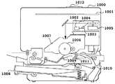
図1は本発明を適用可能な文字パターン出力装置の一例の構成を示す断面図であり、例えばレーザビーム・プリンタ(LBP)の場合を示す。
【0026】
図1において、1000はLBP本体であり、外部に接続されているホスト・コンピュータから供給される印刷情報(文字コード等)やフォーム情報あるいはマクロ命令等を入力して記憶するとともに、それらの情報に従って対応する文字パターンやフォーム・パターン等を作成し、記録媒体である記録紙等に像を形成する。以下では、LBP本体1000をプリンタ1000と称する。1012は操作パネルを有する操作部であり、操作のための複数のスイッチおよびLED/LCD表示器等を備えている。
【0027】
1001はプリンタ制御ユニットであり、プリンタ1000全体の制御およびホスト・コンピュータから供給される文字情報等の解析をする。このプリンタ制御ユニット1001は、主に文字情報を対応する文字パターンのビデオ信号に変換してレーザ・ドライバ1002に出力する。レーザ・ドライバ1002は半導体レーザ1003を駆動するための回路であり、入力されたビデオ信号に応じて半導体レーザ1003から出射されるレーザ光1004をオン/オフ切り換えする。
【0028】
レーザ光1004は回転多面鏡1005で回転面方向に偏光されて静電ドラム1006上を走査露光する。これにより、静電ドラム1006上には文字パターンの静電潜像が形成されることになる。この潜像は、静電ドラム1006周囲に配設された現像ユニット1007により現像された後、記録紙に転写される。この記録紙にはカット・シート記録紙を用いる。カット・シート記録紙はプリンタ1000に装着した用紙カセット1008に収納され、給紙ローラ1009および搬送ローラ1010、1011により装置内に取り込まれて、静電ドラム1006に供給される。
【0029】
またプリンタ1000には、拡張スロット(図示せず)を少なくとも1個以上備え、内蔵インタフェースに加えてLAN等に接続するオプション・インタフェース・ボード等の入出力デバイスを接続できるように構成されている。
【0030】
図2は本発明の一実施の形態を示す出力制御システムの構成を説明するブロック図である。なおここでは、図1に示したレーザビーム・プリンタを例にして説明する。
【0031】
図2において、3000はホスト・コンピュータで、ROM3のプログラムROM332に記憶された文書処理プログラム等に基づいて図形,イメージ,文字,表(表計算等を含む)等が混在した文書処理を実行するCPU1を備え、システム・ バス4に接続される各デバイスをCPU1が総括的に制御する。
【0032】
また、このROM3のプログラムROM332には、上記文書処理を実行した結果出力される情報をプリンタが解析可能なデータへ変換/プリンタ用言語を付加するプリンタ・ドライバ等CPU1の制御プログラム等を記憶し、ROM3のフォントROM331には上記文書処理の際に使用するフォント・データ等を記憶し、ROM3のデータROM333は上記文書処理等を行う際に使用する各種データを記憶する。RAM2は、CPU1のメイン・メモリ,ワーク・エリア等として機能する。キーボード・コントローラ(KBC)5は、キーボード9やボインティング・デバイス(図示せず)からのキー入力を制御する。
【0033】
CRTコントローラ(CRTC)6は、CRTディスプレイ(CRT)10の表示を制御する。ディスク・コントローラ(DKC)7は、ブート・プログラム,種々のアプリケーション,フォント・データ,ユーザ・ファイル,編集ファイル等を記憶するハード・ディスク(HD)、フロッピー・ディスク(FD)等の外部記憶装置11とのアクセスを制御する。
【0034】
ネットワーク・インタフェース・コントローラ(NIC)8は、所定の双方向性ネットワーク・インタフェース21を介してプリンタ1000に接続されて、プリンタ1000との通信制御処理を実行する。ネットワーク・インタフェース・コントローラ(NIC)8には、LAN等のネットワークに関するデバイスおよび他の外部装置(それぞれ図示せず)も接続される。
【0035】
なお、CPU1は、例えばRAM2上に設定された表示情報RAMへのアウトライン・ フォントの展開(ラスタライズ)処理を実行し、CRTディスプレイ10上でのWYSIWYG(ウィジウィグ:見たままのものが得られること、即ちディスプレイ上での最終出力形態をその都度確認できること、仕上り希望通りにディスプレイに表示したり、表示通りに出力装置で出力できること)を可能としている。また、CPU1は、CRTディスプレイ10上のマウス・カーソル(図示せず)等で指示されたコマンドに基づいて登録された種々のウインドウを開き、種々のデータ処理を実行する。
【0036】
プリンタ1000において、12はプリンタCPUで、ROM13のプログラムROM132に記憶された制御プログラム等、或いは外部記憶装置14に記憶された制御プログラム等に基づいて、システム・ バス15に接続される各種のデバイスとのアクセスを総括的に制御し、印刷部インタフェース16を介して接続される印刷部(プリンタ・ エンジン)17に出力情報としての画像信号を出力する。また、このROM13のプログラムROM132には、後述する図3のフロー・チャートで示されるようなCPU12の制御プログラム等を記憶する。
【0037】
ROM13のフォントROM131には、上記出力情報を生成する際に使用するフォント・データ等を記憶する。ハード・ディスク等の外部記憶装置14が無いプリンタの場合には、ROM13のデータROM133には、ホスト・コンピュータ上で利用される情報等を記憶している。
【0038】
入出力部18は操作のためのスイッチおよびLED表示器等を備え、ネットワークインタフェース21からネットワーク・ボード2000を介して操作・入力を行なうことで、CPU12によりホスト・コンピュータ3000との通信処理を制御可能となっており、プリンタ(LBP本体)1000内の情報等をホスト・コンピュータ3000に通知可能に構成されている。
【0039】
RAM19はCPU12のメイン・メモリ、ワーク・エリア等として機能し、増設ポート(図示せず)に接続されるオプションRAMによりメモリ容量を拡張することができるように構成されている。なお、RAM19は、出力情報展開領域、環境データ格納領域、フォント・テーブル作成領域、NVRAM等に用いられる。前述したハード・ディスク(HD)、ICカード等の外部記憶装置14は、ディスク・コントローラ(DKC)20によりアクセスを制御される。この外部記憶装置14はオプションとして接続され、フォント・データ、エミュレーション・プログラム、フォーム・データ等を記憶する。
【0040】
また、前述した外部記憶装置は1個に限らず、少なくとも1個以上備え、内蔵フォントに加えてオプション・ フォント・カード,言語系の異なるプリンタ制御言語を解釈するプログラムを格納した外部記憶装置を複数接続できるように構成されていても良い。さらに、NVRAM(図示せず)を有し、操作部1012からのプリンタモード設定情報を記憶するようにしても良い。
【0041】
上記のように構成されたプリンタ制御システムにおいて、以降図3および図4に示すフロー・チャートおよび図5、図6、図7、図8を参照して、本発明の実施の形態を詳述する。
【0042】
(第1の実施の形態)
図3は、本発明におけるプリンタ1000の電源起動時に装着された機器および設定値が変更された場合のステータス・プリント処理を示すフロー・チャートである。
【0043】
なお、同フロー・チャートおよび以下のフロー・チャートにおいて、各ステップ番号に S を付した。また、図3のフロー・チャートの制御手順はROM13のプログラムROM132に記憶されている。
【0044】
プリンタ1000が電源オンされるとS301において現在装着されている機器情報およびプリンタ1000に記憶されている設定情報を取得し、ステータス・プリントに出力されるシステム構成情報を生成する。このシステム構成情報は、過去一世代分が保持されている。つまり、前回装着されていた機器情報や前回の設定情報までが保持されている。S302で前回起動時に外部記憶装置14の所定の格納領域に格納されたシステム構成情報を読み出すと、S303において、S301で生成したシステム構成情報とS302で取得したシステム構成情報の内容を比較する。
【0045】
S304では、この比較結果に応じてシステム構成が変更されたか判断し、判断結果に応じて分岐する。比較したシステム構成情報の内容が変わっていなければ変更がないとして終了する。一方、比較した情報の内容が変わっていればシステム構成が変更されたと判断し、S305へ進んでS301で取得した現在のシステム構成情報からステータス・プリント出力データを生成する。
【0046】
次にS306において、S303で比較した内容のうち変更を確認した項目の値について、S305で生成したステータス・プリント出力データの該当箇所の出力形式を変更する。さらにS307では、S301で取得した設定情報から現在の排紙の向きの初期設定値を読み出して取得する。
【0047】
排紙の向きの初期設定値を読み出すとS308で、この設定値により縦送りかを判断し、判断結果に応じて分岐する。ここで排紙の向きが縦送りに設定されていると判断した場合にはS309に進み、ステータス・プリント出力時の排紙の向きを横送りに設定し、S311で印刷部においてステータス・プリントを処理して記録媒体に印刷出力する。
【0048】
一方、S308で横送りに設定されていると判定した場合には、S310でステータス・プリントの排紙の向きを縦送りに設定してS311の出力処理へ進む。S311でのステータス・プリントの印刷出力処理を行なうと、S312に進んで現在のシステム構成情報を外部記憶装置14の所定の格納領域に格納し、処理を終了する。
【0049】
(第2の実施の形態)
図4は、プリンタ1000に装着された機器および設定値が変更された場合に、ホスト・コンピュータ3000でプリンタ1000に関する情報表示を行なう場合の、本発明による処理を示すフロー・チャートである。
【0050】
なお、このフロー・チャートの制御手順を含んだプログラムは外部記憶装置11に記憶されており、当該プログラム実行時にDKC7を介してRAM2に展開され処理される。
【0051】
ホスト・コンピュータ3000上でプログラムが実行されると、まずS401で、出力装置であるプリンタ1000に対して現在のシステム構成情報の取得要求命令を送信する。
【0052】
システム構成情報を要求するとS402でこれに対する応答を判定し、応答状況に応じて分岐する。所定の時間内にプリンタ1000から応答があったと判定した場合はS403に進み、要求先のプリンタ(プリンタ1000)からシステム構成情報を受信する。続くS404では、前回プログラムを起動時に外部記憶装置11の所定の格納領域に格納されたシステム構成情報を読み出し、S405においてS403で受信したシステム構成情報とS404で取得したシステム構成情報の内容を比較する。S406では、この比較結果に応じてシステム構成が変更されたか判断し、判断結果に応じて分岐する。
【0053】
S406で比較したシステム構成情報の内容が変わってればシステム構成が変更されたと判断し、S407へ進んでS403で受信取得したシステム構成情報の更新された項目値について他の項目値と異なる表示書式でCRTディスプレイ10で表示されるように書式変更処理する。さらにS408において、S407と同様に更新された項目の出力装置(ホスト・コンピュータ3000)での表示に係わるビットマップ図の書式変更処理を行なって、S409においてCRTディスプレイ10のデバイス表示ウインドウ(図示せず)にシステム構成情報に関する画像および情報を表示した後、S410において本処理で受信した現在のシステム構成情報を外部記憶装置11の所定のシステム構成情報格納領域に格納し、処理を終了する。
【0054】
なお、上記S402において所定時間内に応答がない場合は、S412に進んでエラー通知して処理を終了する。上記S404においてシステム構成が変更されていない場合はS411に進み、S407,S408の変更処理を行なうことなくデバイス表示ウインドウ(図示せず)にシステム構成情報に関する画像および情報を表示した後、処理を終了する。
【0055】
(他の実施の形態)
図5は上記第1の実施の形態によって印刷処理されたステータス・プリントの出力例を示し、図の出力イメージは本発明に係わる出力装置(プリンタ1000)から出力媒体へ出力され、機器情報および設定情報を示している。
【0056】
たとえばS301で2000枚給紙カセットが新規に装着されたことを検知した場合には、このカセットを新規に追加装着したことを識別可能な、たとえば511で示される様なビットマップ画像アイコンを印刷出力する。このアイコン511は、「 2000」 という情報と、「 ついか」 という情報と、図示の給紙カセットの図形を含んでいる。
【0057】
さらに、設定項目の値の変更を検知した場合、例えば排紙モードの初期設定値が変更された場合には、512で示されるような他の項目値とは異なるフォント(この例では、明朝体に対してゴシック体)の強調文字を用いて強調出力処理を行なうことで変更箇所を明示的に表示する。513,514で示される項目も同様に強調出力処理することができる。
【0058】
また、システム構成情報は、第1の実施の形態では過去一世代分の情報が保持されていたが、さらに過去複数世代の情報を保持し、上記ステータス・プリントの出力に変更履歴を加えて印刷するようにしてもよい。さらに、システム構成情報の変更がホスト・コンピュータ3000からの遠隔操作によるものか、あるいはプリンタ1000の操作部1012からの制御によるものかを記憶することで、より詳細に機器情報を把握することが可能である。
【0059】
さらに図6のシステム構成情報を格納する記憶媒体のメモリマップ図を参照し、上記第2の実施の形態におけるシステム構成情報を外部記憶装置11に格納する場合の処理について詳述する。この場合、図6において601で示されるように、ホスト・コンピュータ3000の外部記憶装置11の所定のシステム構成情報格納領域は、図6において602で示されるような各出力装置毎にシステム構成情報が格納される。
【0060】
ネットワークを介してプリンタ1000およびホスト・コンピュータ3000が接続されている場合、通常、ネットワーク上にプリンタ1000以外の複数の同等の処理が可能な出力装置(プリンタ装置)が存在する場合がある。この場合、図6において601で示されるように、ホスト・コンピュータ3000の外部記憶装置11の所定のシステム構成情報格納領域603は、各出力装置毎に格納される。
【0061】
さらに、これら各々の出力装置のシステム構成情報の格納先を識別するための識別子としてたとえばMAC(Medium Access Control )アドレスが、システム構成情報格納領域603に対応したMACアドレス報格納領域602に格納される。このMACアドレスで、装置を一意に識別することができる。
【0062】
なお図7および図8に示す両ウインドウは、本発明の実施の形態によってCRTディスプレイ10に表示される、プリンタ1000に関するシステム構成情報の表示結果の例である。
【0063】
例えば2000枚給紙カセット(ペーパー・デッキ)が新たに装着された場合には、出力装置機器情報を示す図7のビットマップ図において、701で示されるようなビットマップ画像をウインドウ内で表示し、視覚的に変更箇所を表現している。このビットマップ画像701は、当該変更箇所の濃淡を変えて強調表示した図示のコピー機の図形と、「 追加」 という情報とを含んでいる。
【0064】
また図7において、追加されたペーパー・デッキについて他の給紙部とは異なる書体の表示702で給紙部情報について表示を行なう。さらに図7において、変更箇所に関する詳細情報703を表示してもよい。
【0065】
図8はシステム構成情報に関してさらに詳細な表示を行なう場合の表示結果の例であり、設定情報を示すビットマップ図である。
【0066】
図8において801で示されるように、変更された項目について他の項目とは異なるゴシック体等の強調文字を用いて表示を行なう。
【0067】
また、上記の実施の形態では、プリンタ1000の電源起動時あるいは、ホスト・コンピュータ3000上の制御プログラム起動時にプリンタ1000のシステム構成情報の変更を検知する処理手順となっているが、ホスト・コンピュータ3000あるいはプリンタ1000の操作部1012より設定変更が行なわれたことを検知し、この検知結果に基づいてステータス・プリントを印刷出力するか、あるいはホスト・コンピュータ3000のCRTディスプレイ10に表示出力するようにしてもよい。
【0068】
以上の通り本発明の実施の形態によれば、増設機器の追加あるいは出力装置の設定変更に応じて、ステータス・プリントを印刷することで出力装置に新たに装着された機器情報や出力装置設定値の変更の有無を視覚的に明示することが可能となり、出力装置の状態変化を容易に把握することができる。また、ホスト・コンピュータ上に出力装置のシステム構成情報の変更内容を表示することで、遠隔地にある出力装置や複数の出力装置の変更等を直接確認する必要なしに変更箇所を一元的に把握することが可能であり、より一層の機器管理の効率化を図ることができる。
【0069】
なお、上記した本発明の目的は、前述した実施の形態の機能を実現するソフトウェアのプログラムコードを記録した記憶媒体を、システムあるいは装置に供給し、そのシステムあるいは装置のコンピュータ(またはCPUやMPU等の処理装置)が記憶媒体に格納されたプログラムコードを読み出して実行することによっても、達成されることはいうまでもない。
【0070】
この場合、記憶媒体から読み出されたプログラムコード自体が本発明の新規な機能を実現することになり、そのプログラムコードを記憶した記憶媒体が本発明を構成することになる。
【0071】
プログラムコードをコンピュータ等に供給するための記憶媒体としては、例えば、フロッピー・ディスク、ハード・ディスク、光ディスク、光磁気ディスク、CD−ROM、CD−R、磁気テープ、不揮発性のメモリ・カード、ROMなどを用いることができる。
【0072】
また、コンピュータが読み出したプログラムコードを実行することにより、前述した実施の形態の機能が実現されるだけでなく、そのプログラムコードの指示に基づき、コンピュータ上で稼動しているOS(オペレーティング・システム)などが、実際の処理の一部または全部を行い、その処理によって前述した実施の形態の機能が実現される場合も含まれることは言うまでもない。
【0073】
さらに、記憶媒体から読み出されたプログラムコードが、コンピュータに挿入された機能拡張ボードやコンピュータに接続された機能拡張ユニットに備わるメモリに書き込まれた後、そのプログラムコードの指示に基づき、その機能拡張ボードや機能拡張ユニットに備わるCPUなどが実際の処理の一部または全部を行い、その処理によって前述した実施の形態の機能が実現される場合も含まれることは言うまでもない。
【0074】
【発明の効果】
以上、詳述したように本発明の画像出力装置および方法、画像処理装置および方法、並びに記憶媒体によるステータス・プリント出力制御システムでは、画像出力装置に新たに装着された機器情報や出力の設定値の変更の有無を視覚的に明示してユーザに知らせることが可能であり、さらに、ホスト・コンピュータ等の画像処理装置上に画像出力装置のシステム構成情報の変更内容を表示することで、遠隔地にある画像出力装置や複数の画像出力装置の変更等を通信媒体を介して一元的に把握することが可能であり、ネットワーク上でより一層の機器管理の効率化を図ることができるという効果がある。
【図面の簡単な説明】
【図1】レーザビーム・プリンタの内部構造を示す断面図である。
【図2】本発明の各実施の形態におけるプリンタ制御システムの構成を説明するブロック図である。
【図3】本発明の第1の実施の形態の処理の流れを示すフロー・チャートである。
【図4】本発明の第2の実施の形態の処理の流れを示すフロー・チャートである。
【図5】本発明に係わる画像出力装置(プリンタ)から出力媒体へ出力される機器情報および設定情報を示すステータス・プリントの出力イメージの説明図である。
【図6】本発明に係わる出力制御システムで画像出力装置のシステム構成情報を格納する記憶媒体のメモリマップ図である。
【図7】本発明に係わる画像処理装置(ホスト・コンピュータ)上に表示される画像出力装置機器情報を示すビットマップ図である。
【図8】本発明に係わる画像処理装置上に表示される画像出力装置の設定情報を示すビットマップ図である。
【符号の説明】
1,12 CPU
2,19 RAM
3,13 ROM
4,15 システム・ バス
11,14 外部記憶装置
16 印刷部インタフェース
17 印刷部
131,331 フォントROM
132,332 プログラムROM
133,333 データROM
511 アイコン
512〜514,702,801 強調文字
1000 プリンタ(LBP本体)
1012 操作部
2000 ネットワーク・ボード
3000 ホスト・コンピュータ[0001]
BACKGROUND OF THE INVENTION
The present invention relates to an image output apparatus and method, an image processing apparatus and method, and a storage medium, and more particularly to an image output apparatus such as a printer connected to a host computer or the like via a predetermined communication medium such as a network and output control thereof. The present invention relates to an image output method to be performed, an image processing apparatus corresponding to the host computer, the image processing method, and a storage medium storing a program of the method.
[0002]
[Prior art]
2. Description of the Related Art Conventionally, an output device that prints out device information of a device mounted on the device and setting information such as a printer device on a recording sheet or the like is known.
[0003]
The device information and setting information are transmitted and output to a host computer connected via a communication medium such as a network, and displayed as a bitmap image or character information corresponding to the transmitted information on the host computer display or the like. Software is known.
[0004]
Furthermore, some of the software provide a processing system that can change the setting information of the output device based on information displayed using a graphical user interface or the like.
[0005]
[Problems to be solved by the invention]
However, in the above technique, the information to be output to the output medium and the information to be displayed on the display of the host computer are only current information or recently acquired information. For this reason, there is a problem that it is difficult to determine which information has been updated when the setting of the output device is changed or when the extension information is installed and the device information and setting information are updated.
[0006]
Accordingly, the present invention has been made in view of the above-described problems, and an image output apparatus that solves the above-described problems by changing an output image in accordance with a change in apparatus settings or a change in the mounting state of equipment. And a method, an image processing apparatus and method, and a storage medium storing a program of the method.
[0007]
One aspect of the present invention devised to solve the above problem is an image output apparatus provided with an additional device mounting means, wherein the expansion based on the detection that the additional device is mounted on the additional device mounting means. Device information about the device andAboveAcquisition means for acquiring system configuration information including a value of a setting item relating to print output of the image output apparatus, comparison means for comparing the system configuration information already acquired by the acquisition means with newly acquired system configuration information, Based on a comparison result by the comparison unit, a detection unit that detects a change in the mounting state of the additional device and a change in the setting item, an image generation unit that generates image information related to the system configuration information, and the detection unit Based on the detection result and the image information generated by the image generation means, when the installation of a new extension device is detected with respect to the extension device mounting means, the newly installed extension deviceRepresents typeInformation andAboveThe fact that the expansion device is newly installedExpressedThroughKnowledgeWhen the image including the information is printed out and the value of the setting item is changed, the image indicating the changed value is different from the image indicating the value of the other setting item.outputOutput means for controlling the output unit so as to print out in a format is provided.
[0008]
here,The value of the setting item included in the system configuration information may include information regarding the paper discharge mode..
[0009]
here,The control of the output unit by the output unit may be performed in response to installation of a new extension device or a change in the value of the setting item..
[0010]
here,The system configuration information holds a plurality of information changed in the past, and the output means controls the output unit to print out an image including a change history based on the held information. May.
[0011]
Another aspect of the present invention devised to solve the above-described problem relates to an extension device mounted on the image output apparatus in an image processing apparatus that communicates with the image output apparatus via a predetermined communication medium. Acquiring means for acquiring system configuration information including device information and setting item values relating to print output of the image output device, comparing system configuration information already acquired by the acquiring means with newly acquired system configuration information Comparing means, detecting means for detecting a change in the mounting state of the additional device and a change in the setting item based on a comparison result by the comparing means, an image generating means for generating image information related to the system configuration information, and Based on the detection result by the detection unit and the image information generated by the image generation unit, a new expansion device is added to the expansion device mounting unit. In the case of detecting the attachment of the newly mounted additional equipmentRepresents typeInformation andAboveThe fact that the expansion device is newly installedExpressedThroughKnowledgeDisplay means for displaying an image including information and displaying the image indicating the changed value in a display format different from the image indicating the value of the other setting item when the value of the setting item is changed It is characterized by providing.
[0012]
Here, the value of the setting item included in the system configuration information may include information regarding the paper discharge mode.
[0013]
here,The system configuration information may hold a plurality of information changed in the past, and the display means may display an image including a change history based on the held information..
[0014]
Another aspect of the present invention devised to solve the above problem is that, in an image output method of an image output apparatus provided with an additional device mounting means, the additional device is mounted on the additional device mounting means. Device information related to the additional device based on detection andAboveAn acquisition step of acquiring system configuration information including a value of a setting item relating to the print output of the image output device; a comparison step of comparing the system configuration information already acquired in the acquisition step with the newly acquired system configuration information; Based on the comparison result in the comparison step, a detection step for detecting a change in the mounting state of the extension device and a change in the setting item, an image generation step for generating image information related to the system configuration information, and a detection step Based on the detection result and the image information generated in the image generation step, when the installation of a new extension device is detected with respect to the extension device mounting means, the newly installed extension deviceRepresents typeInformation andAboveThe fact that the expansion device is newly installedExpressedThroughKnowledgeWhen the image including the information is printed out and the value of the setting item is changed, the image indicating the changed value is different from the image indicating the value of the other setting item.outputAn output step for controlling the output unit so as to print out in a format is provided.
[0015]
Here, the value of the setting item included in the system configuration information may include information regarding the paper discharge mode.
[0016]
here,The control of the output unit in the output step may be performed in response to installation of a new extension device or detection of a change in the value of the setting item..
[0017]
Here, the system configuration information holds a plurality of information changed in the past, and controls the output unit to print out an image including a change history based on the held information in the output step. It may be a thing.
[0018]
Another aspect of the present invention devised to solve the above problem is an image processing method of an image processing apparatus that communicates with an image output apparatus via a predetermined communication medium, and is attached to the image output apparatus. An acquisition step of acquiring system configuration information including device information relating to the added expansion device and a setting item value relating to the print output of the image output device, and a system in which the system configuration information already acquired in the acquisition step is newly acquired A comparison step for comparing with configuration information, a detection step for detecting a change in the mounting state of the additional device and a change in the setting item based on a comparison result in the comparison step, and image generation for generating image information related to the system configuration information And the detection result in the detection step and the image generated in the image generation step Based on distribution, when detecting the mounting of a new expansion device relative to the extension device mounting means, of the newly mounted additional equipmentRepresents typeInformation andAboveThe fact that the expansion device is newly installedExpressedThroughKnowledgeA display step for displaying an image including information and displaying an image indicating the changed value in a display format different from an image indicating the value of another setting item when the value of the setting item is changed It is characterized by having.
[0019]
here,The value of the setting item included in the system configuration information may include information regarding the paper discharge mode.
[0020]
here,The system configuration information may hold a plurality of information changed in the past, and display an image including a change history based on the held information in the display step..
[0021]
Another aspect of the present invention devised to solve the above-described problems is a storage medium in which a program is stored so as to be readable by a computer, and the program read by the computer is stored in the computer. An acquisition step of acquiring system configuration information including device information related to the additional device based on detection that the additional device is mounted on the additional device mounting means included in the output device and a setting item value related to the print output of the image output device. A comparison step for comparing the system configuration information already acquired in the acquisition step with the newly acquired system configuration information, a change in the mounting state of the extension device and the setting item based on the comparison result in the comparison step Detection step for detecting a change in image, and image generation for generating image information related to the system configuration information If the installation of a new extension device is detected with respect to the extension device mounting means based on the detection result in the detection step and the image information generated in the image generation step, the newly installed extension EquipmentRepresents typeInformation andAboveThe fact that the expansion device is newly installedExpressedThroughKnowledgeWhen the image including the information is printed out and the value of the setting item is changed, the image indicating the changed value is different from the image indicating the value of the other setting item.outputAn output step for controlling the output unit to execute print output in a format is executed.
Another aspect of the present invention devised to solve the above problem is a storage medium storing a program so as to be readable by a computer, and the program read by the computer is stored in the computer in a predetermined manner. An acquisition step of acquiring system configuration information including device information relating to an additional device attached to an image processing apparatus that communicates with the image output apparatus via the communication medium and a value of a setting item relating to print output of the image output apparatus; The comparison step of comparing the system configuration information already acquired in the acquisition step with the newly acquired system configuration information, the change in the mounting state of the additional device and the setting item based on the comparison result in the comparison step A detection step for detecting a change, and an image generation step for generating image information relating to the system configuration information. In addition, when the installation of a new extension device is detected in the extension device mounting means based on the detection result in the detection step and the image information generated in the image generation step, the newly installed extension device ofRepresents typeInformation andAboveThe fact that the expansion device is newly installedExpressedThroughKnowledgeA display step for displaying an image including information and displaying an image indicating the changed value in a display format different from an image indicating the value of another setting item when the value of the setting item is changed Is executed.
[0022]
According to the present invention configured as described above, it is possible to print an output image such as a status / print according to the addition of an additional device or a setting change of the image output device, and grasps a state change related to the image output device. can do. In addition, according to another invention, it is possible to grasp the changed part of the image output device from an image processing device such as a host computer or the like separated via a communication medium without directly checking the image output device. Become.
[0023]
DETAILED DESCRIPTION OF THE INVENTION
Before describing the configuration of the embodiment of the present invention, the configuration of a laser beam printer having an open architecture suitable for applying the present invention will be described with reference to FIGS.
[0024]
Needless to say, the printer to which the present invention is applied is not limited to a laser beam printer, and may be a printer of another printing method.
[0025]
FIG. 1 is a cross-sectional view showing a configuration of an example of a character pattern output apparatus to which the present invention can be applied, and shows a case of a laser beam printer (LBP), for example.
[0026]
In FIG. 1,
[0027]
[0028]
The
[0029]
The
[0030]
FIG. 2 is a block diagram for explaining the configuration of the output control system according to the embodiment of the present invention. Here, the laser beam printer shown in FIG. 1 will be described as an example.
[0031]
In FIG. 2,
[0032]
In addition, the
[0033]
A CRT controller (CRTC) 6 controls display on a CRT display (CRT) 10. A disk controller (DKC) 7 is an
[0034]
A network interface controller (NIC) 8 is connected to the
[0035]
The
[0036]
In the
[0037]
The
[0038]
The input /
[0039]
The
[0040]
The above-described external storage device is not limited to one, but includes at least one external storage device that stores options, fonts, cards, and programs for interpreting different printer control languages in addition to built-in fonts. You may be comprised so that it can connect. Further, an NVRAM (not shown) may be provided, and printer mode setting information from the
[0041]
In the printer control system configured as described above, the embodiment of the present invention will be described in detail with reference to the flowcharts shown in FIGS. 3 and 4 and FIGS. 5, 6, 7, and 8. .
[0042]
(First embodiment)
FIG. 3 is a flowchart showing the status printing process when the device mounted at the time of power activation of the
[0043]
In the flow chart and the following flow chart, S is given to each step number. 3 is stored in a
[0044]
When the
[0045]
In S304, it is determined whether the system configuration has been changed according to the comparison result, and the process branches according to the determination result. If the contents of the compared system configuration information have not changed, the process ends with no change. On the other hand, if the contents of the compared information have changed, it is determined that the system configuration has been changed, and the process proceeds to S305 to generate status print output data from the current system configuration information acquired in S301.
[0046]
Next, in S306, the output format of the corresponding part of the status / print output data generated in S305 is changed for the value of the item confirmed to be changed among the contents compared in S303. In step S307, the initial setting value of the current discharge direction is read out and acquired from the setting information acquired in step S301.
[0047]
When the initial setting value of the paper discharge direction is read, in S308, it is determined whether the longitudinal feeding is performed based on this setting value, and the process branches according to the determination result. If it is determined that the paper discharge direction is set to vertical feed, the process advances to step S309 to set the paper discharge direction at the time of status print output to horizontal feed. In step S311, the print unit performs status printing. Processed and printed out on a recording medium.
[0048]
On the other hand, if it is determined in S308 that the horizontal feed is set, the status print paper discharge direction is set to the vertical feed in S310, and the process proceeds to the output process in S311. When the status print output process in S311 is performed, the process proceeds to S312 to store the current system configuration information in a predetermined storage area of the
[0049]
(Second Embodiment)
FIG. 4 is a flow chart showing processing according to the present invention when the
[0050]
The program including the control procedure of the flow chart is stored in the
[0051]
When the program is executed on the
[0052]
When system configuration information is requested, a response to this is determined in S402, and the process branches according to the response status. If it is determined that there is a response from the
[0053]
If the contents of the system configuration information compared in S406 have changed, it is determined that the system configuration has been changed, and the process proceeds to S407, where the updated item values of the system configuration information received and acquired in S403 are different from other item values. The format change process is performed so as to be displayed on the
[0054]
If there is no response within the predetermined time in S402, the process proceeds to S412 and an error is notified and the process is terminated. If the system configuration has not been changed in S404, the process proceeds to S411, and the image and information related to the system configuration information are displayed on the device display window (not shown) without performing the change processing in S407 and S408, and then the processing ends. To do.
[0055]
(Other embodiments)
FIG. 5 shows an output example of the status print that has been printed according to the first embodiment. The output image in the figure is output from the output device (printer 1000) according to the present invention to the output medium, and the device information and settings are displayed. Information is shown.
[0056]
For example, when it is detected in S301 that a 2000-sheet paper cassette is newly installed, a bitmap image icon as indicated by 511, for example, which can identify that this cassette is newly installed is printed out. To do. This icon 511 includes information “2000”, information “Tsukaika”, and a graphic of the paper cassette shown in the figure.
[0057]
Further, when a change in the value of the setting item is detected, for example, when the initial setting value of the paper discharge mode is changed, a font different from other item values as indicated by 512 (in this example, Mincho) The changed part is explicitly displayed by performing the emphasis output process using the emphasis character of the Gothic type). The items indicated by 513 and 514 can also be subjected to emphasis output processing.
[0058]
In the first embodiment, the system configuration information has been retained for the past generation. However, the system configuration information is also retained for the past multiple generations, and is printed by adding the change history to the status print output. You may make it do. Furthermore, it is possible to grasp device information in more detail by storing whether the change in the system configuration information is a remote operation from the
[0059]
Further, a process for storing the system configuration information in the second embodiment in the
[0060]
When the
[0061]
Further, for example, a MAC (Medium Access Control) address is stored in the MAC address
[0062]
Both windows shown in FIGS. 7 and 8 are examples of display results of system configuration information related to the
[0063]
For example, when a 2000 sheet cassette (paper deck) is newly installed, a bitmap image as indicated by 701 in the bitmap diagram of FIG. 7 showing the output device information is displayed in the window. , Visually expressing changes. The
[0064]
In FIG. 7, the paper feed unit information is displayed on the added paper deck with a
[0065]
FIG. 8 is an example of a display result when a more detailed display is made with respect to the system configuration information, and is a bit map showing the setting information.
[0066]
As indicated by
[0067]
In the above-described embodiment, the processing procedure for detecting a change in the system configuration information of the
[0068]
As described above, according to the embodiment of the present invention, in response to the addition of an additional device or the setting change of the output device, the device information newly installed in the output device or the output device setting value by printing the status print It is possible to visually indicate whether or not there is a change, and it is possible to easily grasp the state change of the output device. In addition, by displaying the change contents of the system configuration information of the output device on the host computer, the change location can be grasped centrally without the need to directly check the change of the output device or multiple output devices in the remote place. It is possible to improve the efficiency of device management.
[0069]
It is to be noted that the object of the present invention described above is to supply a storage medium storing software program codes for realizing the functions of the above-described embodiments to a system or apparatus, and the computer of the system or apparatus (or CPU, MPU, etc.) Needless to say, this can also be achieved by reading and executing the program code stored in the storage medium.
[0070]
In this case, the program code itself read from the storage medium realizes the novel function of the present invention, and the storage medium storing the program code constitutes the present invention.
[0071]
As a storage medium for supplying the program code to a computer or the like, for example, a floppy disk, a hard disk, an optical disk, a magneto-optical disk, a CD-ROM, a CD-R, a magnetic tape, a nonvolatile memory card, a ROM Etc. can be used.
[0072]
Further, by executing the program code read by the computer, not only the functions of the above-described embodiments are realized, but also an OS (Operating System) running on the computer based on an instruction of the program code. Needless to say, a case where the function of the above-described embodiment is realized by performing part or all of the actual processing and the processing is included.
[0073]
Further, after the program code read from the storage medium is written to a memory provided in a function expansion board inserted into the computer or a function expansion unit connected to the computer, the function expansion is performed based on the instruction of the program code. It goes without saying that the CPU or the like provided in the board or the function expansion unit performs part or all of the actual processing and the functions of the above-described embodiments are realized by the processing.
[0074]
【The invention's effect】
As described above, in the image output device and method, the image processing device and method, and the status / print output control system using the storage medium according to the present invention, the device information newly installed in the image output device and the output setting value It is possible to notify the user by visually indicating whether or not there has been a change, and by displaying the change contents of the system configuration information of the image output device on an image processing device such as a host computer, The change of the image output device or the plurality of image output devices in the network can be grasped centrally through the communication medium, and it is possible to further improve the efficiency of device management on the network. is there.
[Brief description of the drawings]
FIG. 1 is a cross-sectional view showing the internal structure of a laser beam printer.
FIG. 2 is a block diagram illustrating a configuration of a printer control system in each embodiment of the present invention.
FIG. 3 is a flowchart showing the flow of processing according to the first embodiment of the present invention.
FIG. 4 is a flowchart showing a process flow of the second embodiment of the present invention.
FIG. 5 is an explanatory diagram of an output image of a status print showing device information and setting information output from an image output apparatus (printer) according to the present invention to an output medium.
FIG. 6 is a memory map diagram of a storage medium for storing system configuration information of an image output apparatus in the output control system according to the present invention.
FIG. 7 is a bit map showing image output apparatus device information displayed on an image processing apparatus (host computer) according to the present invention.
FIG. 8 is a bit map showing setting information of an image output device displayed on an image processing device according to the present invention.
[Explanation of symbols]
1,12 CPU
2,19 RAM
3,13 ROM
4,15 system bus
11, 14 External storage device
16 Printing section interface
17 Printing department
131,331 Font ROM
132,332 Program ROM
133,333 Data ROM
511 icon
512-514, 702, 801 Emphasized characters
1000 Printer (LBP main unit)
1012 Operation unit
2000 Network board
3000 host computer
Claims (16)
前記増設機器装着手段に増設機器が装着されたことの検知に基づく該増設機器に関する機器情報と前記画像出力装置の印刷出力に係る設定項目の値を含むシステム構成情報を取得する取得手段、
前記取得手段により既に取得してあるシステム構成情報を、新たに取得したシステム構成情報と比較する比較手段、
前記比較手段による比較結果に基づいて、前記増設機器の装着状態の変化及び前記設定項目の変化を検知する検知手段、
前記システム構成情報に関する画像情報を生成する画像生成手段、並びに、
前記検知手段による検知結果及び前記画像生成手段により生成された画像情報に基づき、前記増設機器装着手段に対して新たな増設機器の装着を検知した場合、該新たに装着された増設機器の種類を表す情報と前記増設機器が新たに装着された旨を表現した通知情報とを含む画像を印刷出力し、及び、前記設定項目の値に変化があった場合、当該変化した値を示す画像を他の設定項目の値を示す画像とは異なる出力形式で印刷出力するように出力部を制御する出力手段
を備えることを特徴とする画像出力装置。In an image output device equipped with an additional device mounting means,
Acquiring means for acquiring system configuration information including the value of the setting item for the print output of the additional the additional equipment related to the device information based on the detection of the additional equipment is attached to the device mounting means and the image output apparatus,
Comparison means for comparing the system configuration information already acquired by the acquisition means with the newly acquired system configuration information;
Based on a comparison result by the comparison unit, a detection unit that detects a change in the mounting state of the additional device and a change in the setting item,
Image generating means for generating image information relating to the system configuration information, and
Based on the detection result by the detection unit and the image information generated by the image generation unit, when the installation of a new extension device is detected with respect to the extension device mounting unit, the type of the newly installed extension device is selected. information and the additional equipment represented an image print output including the newly mounted expresses that the notification information, and, if there is a change in the value of the setting item, an image indicating the changed value An image output apparatus comprising: an output unit that controls an output unit so as to print and output in an output format different from an image indicating values of other setting items.
前記出力手段は、該保持された情報に基づく変更履歴を含めた画像を印刷出力するように前記出力部を制御することを特徴とする請求項1乃至請求項3のいずれか1項に記載の画像出力装置。 The system configuration information holds a plurality of information changed in the past,
And the output means, according to any one of claims 1 to 3, characterized that you control the output unit so as to print out the image, including the change history based on the retained information image output device.
前記画像出力装置に装着されている増設機器に関する機器情報と前記画像出力装置の印刷出力に係る設定項目の値を含むシステム構成情報を取得する取得手段、
前記取得手段により既に取得してあるシステム構成情報を、新たに取得したシステム構成情報と比較する比較手段、
前記比較手段による比較結果に基づいて、前記増設機器の装着状態の変化及び前記設定項目の変化を検知する検知手段、
前記システム構成情報に関する画像情報を生成する画像生成手段、並びに、
前記検知手段による検知結果及び前記画像生成手段により生成された画像情報に基づき、前記増設機器装着手段に対して新たな増設機器の装着を検知した場合、該新たに装着された増設機器の種類を表す情報と前記増設機器が新たに装着された旨を表現した通知情報とを含む画像を表示し、及び、前記設定項目の値に変化があった場合、当該変化した値を示す画像を他の設定項目の値を示す画像とは異なる表示形式で表示する表示手段
を備えることを特徴とする画像処理装置。In an image processing apparatus that communicates with an image output apparatus via a predetermined communication medium,
Acquisition means for acquiring system configuration information including device information relating to an additional device attached to the image output device and a value of a setting item relating to print output of the image output device;
Comparison means for comparing the system configuration information already acquired by the acquisition means with the newly acquired system configuration information;
Based on a comparison result by the comparison unit, a detection unit that detects a change in the mounting state of the additional device and a change in the setting item,
Image generating means for generating image information relating to the system configuration information, and
Based on the detection result by the detection unit and the image information generated by the image generation unit, when the installation of a new extension device is detected with respect to the extension device mounting unit, the type of the newly installed extension device is selected. information and the additional equipment represented by displaying an image including a notification information representing the fact that the newly mounted, and, if there is a change in the value of the setting item, other images showing the changed value An image processing apparatus comprising: display means for displaying in a display format different from an image indicating the value of the setting item.
前記表示手段は、該保持された情報に基づく変更履歴を含めた画像を表示することを特徴とする請求項5または請求項6に記載の画像処理装置。 The image processing apparatus according to claim 5, wherein the display unit displays an image including a change history based on the held information.
前記増設機器装着手段に増設機器が装着されたことの検知に基づく該増設機器に関する機器情報と前記画像出力装置の印刷出力に係る設定項目の値を含むシステム構成情報を取得する取得ステップ、
前記取得ステップにおいて既に取得してあるシステム構成情報を、新たに取得したシステム構成情報と比較する比較ステップ、
前記比較ステップにおける比較結果に基づいて、前記増設機器の装着状態の変化及び前記設定項目の変化を検知する検知ステップ、
前記システム構成情報に関する画像情報を生成する画像生成ステップ、並びに、
前記検知ステップにおける検知結果及び前記画像生成ステップにおいて生成された画像情報に基づき、前記増設機器装着手段に対して新たな増設機器の装着を検知した場合、該新たに装着された増設機器の種類を表す情報と前記増設機器が新たに装着された旨を表現した通知情報とを含む画像を印刷出力し、及び、前記設定項目の値に変化があった場合、当該変化した値を示す画像を他の設定項目の値を示す画像とは異なる出力形式で印刷出力するように出力部を制御する出力ステップ
を有することを特徴とする画像出力方法。In the image output method of the image output apparatus provided with the additional device mounting means,
Acquiring system configuration information including the value of the setting item for the print output of the additional the additional equipment related to the device information based on the detection of the additional equipment is attached to the device mounting means and the image output apparatus,
A comparison step of comparing the system configuration information already acquired in the acquisition step with the newly acquired system configuration information;
Based on the comparison result in the comparison step, a detection step for detecting a change in the mounting state of the extension device and a change in the setting item,
An image generating step for generating image information relating to the system configuration information, and
Based on the detection result in the detection step and the image information generated in the image generation step, when the installation of a new extension device is detected with respect to the extension device mounting means, the type of the newly installed extension device is selected. information and the additional equipment represented an image print output including the newly mounted expresses that the notification information, and, if there is a change in the value of the setting item, an image indicating the changed value An image output method comprising: an output step of controlling an output unit so as to print and output in an output format different from an image showing values of other setting items.
前記出力ステップにおいて、該保持された情報に基づく変更履歴を含めた画像を印刷出力するように前記出力部を制御することを特徴とする請求項8乃至請求項10のいずれか1項に記載の画像出力方法。 11. The output unit according to claim 8, wherein, in the output step, the output unit is controlled to print out an image including a change history based on the held information. Image output method.
前記画像出力装置に装着されている増設機器に関する機器情報と前記画像出力装置の印刷出力に係る設定項目の値を含むシステム構成情報を取得する取得ステップ、
前記取得ステップにおいて既に取得してあるシステム構成情報を、新たに取得したシステム構成情報と比較する比較ステップ、
前記比較ステップにおける比較結果に基づいて、前記増設機器の装着状態の変化及び前記設定項目の変化を検知する検知ステップ、
前記システム構成情報に関する画像情報を生成する画像生成ステップ、並びに、
前記検知ステップにおける検知結果及び前記画像生成ステップにおいて生成された画像情報に基づき、前記増設機器装着手段に対して新たな増設機器の装着を検知した場合、該新たに装着された増設機器の種類を表す情報と前記増設機器が新たに装着された旨を表現した通知情報とを含む画像を表示し、及び、前記設定項目の値に変化があった場合、当該変化した値を示す画像を他の設定項目の値を示す画像とは異なる表示形式で表示する表示ステップ
を有することを特徴とする画像処理方法。In an image processing method of an image processing apparatus that communicates with an image output apparatus via a predetermined communication medium,
An acquisition step of acquiring system configuration information including device information relating to an additional device attached to the image output device and a value of a setting item relating to print output of the image output device;
A comparison step of comparing the system configuration information already acquired in the acquisition step with the newly acquired system configuration information;
Based on the comparison result in the comparison step, a detection step for detecting a change in the mounting state of the extension device and a change in the setting item,
An image generating step for generating image information relating to the system configuration information, and
Based on the detection result in the detection step and the image information generated in the image generation step, when the installation of a new extension device is detected with respect to the extension device mounting means, the type of the newly installed extension device is selected. information and the additional equipment represented by displaying an image including a notification information representing the fact that the newly mounted, and, if there is a change in the value of the setting item, other images showing the changed value An image processing method comprising: a display step of displaying in a display format different from an image indicating the value of the setting item.
前記表示ステップにおいて、該保持された情報に基づく変更履歴を含めた画像を表示することを特徴とする請求項12または請求項13に記載の画像処理方法。 14. The image processing method according to claim 12, wherein an image including a change history based on the held information is displayed in the display step.
画像出力装置が備える増設機器装着手段に増設機器が装着されたことの検知に基づく該増設機器に関する機器情報と前記画像出力装置の印刷出力に係る設定項目の値を含むシステム構成情報を取得する取得ステップ、
前記取得ステップにおいて既に取得してあるシステム構成情報を、新たに取得したシステム構成情報と比較する比較ステップ、
前記比較ステップにおける比較結果に基づいて、前記増設機器の装着状態の変化及び前記設定項目の変化を検知する検知ステップ、
前記システム構成情報に関する画像情報を生成する画像生成ステップ、並びに、
前記検知ステップにおける検知結果及び前記画像生成ステップにおいて生成された画像情報に基づき、前記増設機器装着手段に対して新たな増設機器の装着を検知した場合、該新たに装着された増設機器の種類を表す情報と前記増設機器が新たに装着された旨を表現した通知情報とを含む画像を印刷出力し、及び、前記設定項目の値に変化があった場合、当該変化した値を示す画像を他の設定項目の値を示す画像とは異なる出力形式で印刷出力するように出力部を制御する出力ステップ
を実行させることを特徴とする記憶媒体。A storage medium in which a program is stored so as to be readable by a computer, and the program read by the computer is stored in the computer,
Acquisition of acquiring system configuration information including device information relating to the extension device based on detection that the extension device has been installed in the extension device mounting means included in the image output device, and setting item values relating to print output of the image output device Step,
A comparison step of comparing the system configuration information already acquired in the acquisition step with the newly acquired system configuration information;
Based on the comparison result in the comparison step, a detection step for detecting a change in the mounting state of the extension device and a change in the setting item,
An image generating step for generating image information relating to the system configuration information, and
Based on the detection result in the detection step and the image information generated in the image generation step, when the installation of a new extension device is detected with respect to the extension device mounting means, the type of the newly installed extension device is selected. information and the additional equipment represented an image print output including the newly mounted expresses that the notification information, and, if there is a change in the value of the setting item, an image indicating the changed value A storage medium that executes an output step of controlling an output unit so as to print and output in an output format different from an image showing values of other setting items.
所定の通信媒体を介し画像出力装置と通信を行う画像処理装置に装着されている増設機器に関する機器情報と前記画像出力装置の印刷出力に係る設定項目の値を含むシステム構成情報を取得する取得ステップ、
前記取得ステップにおいて既に取得してあるシステム構成情報を、新たに取得したシステム構成情報と比較する比較ステップ、
前記比較ステップにおける比較結果に基づいて、前記増設機器の装着状態の変化及び前記設定項目の変化を検知する検知ステップ、
前記システム構成情報に関する画像情報を生成する画像生成ステップ、並びに、
前記検知ステップにおける検知結果及び前記画像生成ステップにおいて生成された画像情報に基づき、前記増設機器装着手段に対して新たな増設機器の装着を検知した場合、該新たに装着された増設機器の種類を表す情報と前記増設機器が新たに装着された旨を表現した通知情報とを含む画像を表示し、及び、前記設定項目の値に変化があった場合、当該変化した値を示す画像を他の設定項目の値を示す画像とは異なる表示形式で表示する表示ステップ
を実行させることを特徴とする記憶媒体。A storage medium in which a program is stored so as to be readable by a computer, and the program read by the computer is stored in the computer,
An acquisition step of acquiring system configuration information including device information relating to an extension device attached to an image processing apparatus that communicates with an image output apparatus via a predetermined communication medium, and setting item values relating to print output of the image output apparatus. ,
A comparison step of comparing the system configuration information already acquired in the acquisition step with the newly acquired system configuration information;
Based on the comparison result in the comparison step, a detection step for detecting a change in the mounting state of the extension device and a change in the setting item,
An image generating step for generating image information relating to the system configuration information, and
Based on the detection result in the detection step and the image information generated in the image generation step, when the installation of a new extension device is detected with respect to the extension device mounting means, the type of the newly installed extension device is selected. information and the additional equipment represented by displaying an image including a notification information representing the fact that the newly mounted, and, if there is a change in the value of the setting item, other images showing the changed value A storage medium that executes a display step of displaying in a display format different from an image indicating the value of the setting item.
Priority Applications (1)
| Application Number | Priority Date | Filing Date | Title |
|---|---|---|---|
| JP16394198A JP4274495B2 (en) | 1998-06-11 | 1998-06-11 | Image output apparatus and method, image processing apparatus and method, and storage medium |
Applications Claiming Priority (1)
| Application Number | Priority Date | Filing Date | Title |
|---|---|---|---|
| JP16394198A JP4274495B2 (en) | 1998-06-11 | 1998-06-11 | Image output apparatus and method, image processing apparatus and method, and storage medium |
Publications (2)
| Publication Number | Publication Date |
|---|---|
| JPH11348380A JPH11348380A (en) | 1999-12-21 |
| JP4274495B2 true JP4274495B2 (en) | 2009-06-10 |
Family
ID=15783738
Family Applications (1)
| Application Number | Title | Priority Date | Filing Date |
|---|---|---|---|
| JP16394198A Expired - Fee Related JP4274495B2 (en) | 1998-06-11 | 1998-06-11 | Image output apparatus and method, image processing apparatus and method, and storage medium |
Country Status (1)
| Country | Link |
|---|---|
| JP (1) | JP4274495B2 (en) |
Families Citing this family (5)
| Publication number | Priority date | Publication date | Assignee | Title |
|---|---|---|---|---|
| JP2004227496A (en) * | 2003-01-27 | 2004-08-12 | Sharp Corp | Image processor |
| JP4516782B2 (en) * | 2004-04-30 | 2010-08-04 | Juki株式会社 | Sewing machine control device |
| JP2007080171A (en) * | 2005-09-16 | 2007-03-29 | Ricoh Co Ltd | Apparatus and method for managing device, program, and recording medium |
| US7605933B2 (en) | 2006-07-13 | 2009-10-20 | Ricoh Company, Ltd. | Approach for securely processing an electronic document |
| JP2009193410A (en) | 2008-02-15 | 2009-08-27 | Sharp Corp | Information processing apparatus, information processing system, computer program, and recording medium with the computer program recorded thereon |
Family Cites Families (4)
| Publication number | Priority date | Publication date | Assignee | Title |
|---|---|---|---|---|
| JP2517115B2 (en) * | 1989-07-25 | 1996-07-24 | 松下電送株式会社 | Image communication device |
| US5832298A (en) * | 1995-05-30 | 1998-11-03 | Canon Kabushiki Kaisha | Adaptive graphical user interface for a network peripheral |
| JPH09141977A (en) * | 1995-11-20 | 1997-06-03 | Ricoh Co Ltd | Image forming unit and system |
| JPH09272232A (en) * | 1996-04-05 | 1997-10-21 | Canon Inc | Device for print control, method therefor and storage medium storing control program |
-
1998
- 1998-06-11 JP JP16394198A patent/JP4274495B2/en not_active Expired - Fee Related
Also Published As
| Publication number | Publication date |
|---|---|
| JPH11348380A (en) | 1999-12-21 |
Similar Documents
| Publication | Publication Date | Title |
|---|---|---|
| JP4274495B2 (en) | Image output apparatus and method, image processing apparatus and method, and storage medium | |
| JPH08258380A (en) | Printer controller, printer control system, and printer control method | |
| JPH09190312A (en) | Printing system and data processing method therefor | |
| JP2004192390A (en) | Data processor | |
| JP2004157904A (en) | Printer control program and printer | |
| JPH10187380A (en) | Device for controlling printing and method therefor and storage medium for storing program readable by computer | |
| JP3209858B2 (en) | Print control device and print control method | |
| JPH11191042A (en) | Data processor, data processing method therefor, and storage medium stored with computer-readable program | |
| JP3495876B2 (en) | Character output device, character output method, and storage medium storing computer readable program | |
| JPH10187390A (en) | Information processor, data processing method for information processor and recording medium storing program that can be read by computer | |
| JP2004227075A (en) | Printing system | |
| JP2001282476A (en) | Data processor, printer control, device, data processing method, and storage medium | |
| JPH08328782A (en) | Information processor, information processing method, printer, control method therefor, printing system and control method therefor | |
| JP3209859B2 (en) | Printing equipment | |
| JP2000263895A (en) | Image output control device, status outputting method thereof and memory medium storing program readable by computer | |
| JPH09146521A (en) | Device and method for output control | |
| JPH09191568A (en) | Output device and power supply control thereof | |
| JPH0872362A (en) | Printing device and control method thereof | |
| JPH09179700A (en) | Printer, printing device, printing system, and information processor | |
| JPH1091368A (en) | Print controller and its data processing method and storage medium storing readable program for computer | |
| JP2009031997A (en) | Print control system | |
| JP2004160919A (en) | Printer controller | |
| JP2003099232A (en) | Print controller, printer, print control system, font downloading system determining method, print control method, storage medium and program | |
| JP2000112700A (en) | Device for generating data base, printing system, method for displaying state change of printer and storage medium readable by computer | |
| JP2004192239A (en) | Information processor, printer, print controller and printing system |
Legal Events
| Date | Code | Title | Description |
|---|---|---|---|
| A621 | Written request for application examination |
Free format text: JAPANESE INTERMEDIATE CODE: A621 Effective date: 20050527 |
|
| A521 | Written amendment |
Free format text: JAPANESE INTERMEDIATE CODE: A523 Effective date: 20070625 |
|
| A977 | Report on retrieval |
Free format text: JAPANESE INTERMEDIATE CODE: A971007 Effective date: 20071115 |
|
| A131 | Notification of reasons for refusal |
Free format text: JAPANESE INTERMEDIATE CODE: A131 Effective date: 20071127 |
|
| A521 | Written amendment |
Free format text: JAPANESE INTERMEDIATE CODE: A523 Effective date: 20080128 |
|
| A131 | Notification of reasons for refusal |
Free format text: JAPANESE INTERMEDIATE CODE: A131 Effective date: 20081118 |
|
| RD13 | Notification of appointment of power of sub attorney |
Free format text: JAPANESE INTERMEDIATE CODE: A7433 Effective date: 20090114 |
|
| A521 | Written amendment |
Free format text: JAPANESE INTERMEDIATE CODE: A523 Effective date: 20090119 |
|
| A521 | Written amendment |
Free format text: JAPANESE INTERMEDIATE CODE: A821 Effective date: 20090114 |
|
| TRDD | Decision of grant or rejection written | ||
| A01 | Written decision to grant a patent or to grant a registration (utility model) |
Free format text: JAPANESE INTERMEDIATE CODE: A01 Effective date: 20090227 |
|
| A01 | Written decision to grant a patent or to grant a registration (utility model) |
Free format text: JAPANESE INTERMEDIATE CODE: A01 |
|
| A61 | First payment of annual fees (during grant procedure) |
Free format text: JAPANESE INTERMEDIATE CODE: A61 Effective date: 20090302 |
|
| R150 | Certificate of patent or registration of utility model |
Free format text: JAPANESE INTERMEDIATE CODE: R150 |
|
| FPAY | Renewal fee payment (event date is renewal date of database) |
Free format text: PAYMENT UNTIL: 20120313 Year of fee payment: 3 |
|
| FPAY | Renewal fee payment (event date is renewal date of database) |
Free format text: PAYMENT UNTIL: 20130313 Year of fee payment: 4 |
|
| FPAY | Renewal fee payment (event date is renewal date of database) |
Free format text: PAYMENT UNTIL: 20140313 Year of fee payment: 5 |
|
| LAPS | Cancellation because of no payment of annual fees |