JP2004156865A - Device and method for controlling operation of plasma arc type melting furnace - Google Patents
Device and method for controlling operation of plasma arc type melting furnace Download PDFInfo
- Publication number
- JP2004156865A JP2004156865A JP2002324023A JP2002324023A JP2004156865A JP 2004156865 A JP2004156865 A JP 2004156865A JP 2002324023 A JP2002324023 A JP 2002324023A JP 2002324023 A JP2002324023 A JP 2002324023A JP 2004156865 A JP2004156865 A JP 2004156865A
- Authority
- JP
- Japan
- Prior art keywords
- furnace
- plasma arc
- current
- melting furnace
- current value
- Prior art date
- Legal status (The legal status is an assumption and is not a legal conclusion. Google has not performed a legal analysis and makes no representation as to the accuracy of the status listed.)
- Withdrawn
Links
Images


Classifications
-
- Y—GENERAL TAGGING OF NEW TECHNOLOGICAL DEVELOPMENTS; GENERAL TAGGING OF CROSS-SECTIONAL TECHNOLOGIES SPANNING OVER SEVERAL SECTIONS OF THE IPC; TECHNICAL SUBJECTS COVERED BY FORMER USPC CROSS-REFERENCE ART COLLECTIONS [XRACs] AND DIGESTS
- Y02—TECHNOLOGIES OR APPLICATIONS FOR MITIGATION OR ADAPTATION AGAINST CLIMATE CHANGE
- Y02P—CLIMATE CHANGE MITIGATION TECHNOLOGIES IN THE PRODUCTION OR PROCESSING OF GOODS
- Y02P10/00—Technologies related to metal processing
- Y02P10/25—Process efficiency
Abstract
Description
【0001】
【発明の属する技術分野】
本発明は、炉本体に対向して挿入した主電極と炉底電極との間に発生させたプラズマアークにより炉内を高温に保持してなるプラズマアーク式溶融炉に関し、特にプラズマアーク式溶融炉に発生する迷走電流を検知して運転制御を行う装置及びその方法に関する。
【0002】
【従来の技術】
近年、廃棄物を焼却処理した後の焼却灰等を溶融処理するための炉としてプラズマアーク式溶融炉が広く用いられている。プラズマアーク式溶融炉は、廃棄物の減容化、無害化に有効で、さらに溶融後のスラグの再利用化が可能であることから最も有用な廃棄物処理装置の一つとして挙げられる。
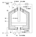
プラズマアーク式溶融炉の一例を図3に示す。図に示されるようにプラズマアーク式溶融炉50は、その炉内側を絶縁性を有する耐火材51で形成された側壁52、炉底54及び炉蓋53で形成され、炉外側を鉄皮55で被覆された炉本体と、前記炉蓋53及び炉底54に絶縁スリーブ56を介して挿入された主電極58及び炉底電極59と、を主要構成としている。
【0003】
かかる構成のプラズマアーク式溶融炉50は、一般的に環状黒鉛電極が用いられることが多く、炉内にプラズマアーク生成ガスを供給しながら電極間に電圧を印加してプラズマアークを生成し被溶融物を溶融処理する。炉内温度は1000℃以上に維持され、炉底部には被溶融物が溶融したスラグ層とメタル層とからなる出滓物が層状に形成される。
かかる溶融炉では炉内が高温に維持されるため、被溶融物として焼却灰等のように被溶融物中に比較的融点が低い塩類が含有されている場合には、塩類がガス中に揮散して炉内壁に付着する。このように付着した塩化カリウムや塩化ナトリウム等の付着物は導電率が高く、炉壁が絶縁不良をおこして迷走電流が発生する惧れがある。
【0004】
迷走電流の炉内導通経路は少なくとも2通り考えられる。炉内導通経路として、炉内壁耐火物に塩類が浸透して絶縁性が劣化した場合に、主電極58から耐火物を経て鉄皮55を通って炉底電極59へ抜ける経路、及び炉内に塩類等からなる付着物が堆積した場合に、主電極58から炉内壁の付着物を通って炉底電極59へ抜ける経路がある。
このような迷走電流が発生すると、炉内を適性温度に維持することができず被処理物の溶融状態が悪化し溶融炉が正常に稼動しなくなり、また炉壁に必要以上の負荷がかかるため損傷が著しくなるという問題が生じる。
【0005】
そこで、図3に示す特開2000−18552公報(特許文献1)では、主電極58と炉底電極59を絶縁する環状の絶縁材57を設け、該絶縁材を挟んで両電極間の電流又は電圧を計測する電流計60等の計測手段を設けている。これにより、絶縁不良による迷走電流を監視可能としている。
また、特開平6−331278号公報(特許文献2)では、炉底電極と絶縁物で隔離された炉底鉄皮間の電圧を測定し、かつ炉底電極から接地用抵抗体に流れる電流を測定して、これらの測定値に基づき炉底電極部の異常電圧を判定することにより、迷走電流による炉鉄皮の損傷を未然に防ぐ構成としている。
【0006】
【特許文献1】
特開2000−18552公報
【特許文献2】
特開平6−331278号公報
【0007】
【発明が解決しようとする課題】
しかしながら、これらの従来技術のように鉄皮の電流又は電圧を計測して迷走電流を監視する方法、若しくは炉底鉄皮の異常電圧を検出して迷走電流を検知する方法は非常に有効な方法であるが、前記したように、炉鉄皮を通る導通経路以外で発生する迷走電流を検知することは不可能であり、溶融炉に発生する迷走電流を完全に把握することはできない。
そこで、本発明はかかる従来技術の問題に鑑み、プラズマアーク式溶融炉における迷走電流の発生を確実に把握することができるとともに、これに基づき溶融炉を好適な状態で運転可能であるプラズマアーク式溶融炉の運転制御装置及びその方法を提供することを目的とする。
【0008】
【課題を解決するための手段】
そこで、本発明はかかる課題を解決するために、
絶縁性耐火物で形成された炉内壁を鉄皮で被覆した炉本体を有し、該炉本体に対向して挿入した主電極及び炉底電極間にプラズマアークを発生させて炉内を高温に保持してなるプラズマアーク式溶融炉の運転制御装置において、
前記主電極と炉底電極の間の電流値を計測する電流計測手段と、
炉外より透過窓を介して炉内のプラズマアーク生成部を撮像する赤外線カメラと、該赤外線カメラにより撮像された画像からプラズマアーク状態を解析する画像処理装置と、からなるプラズマアーク検知手段と、を備え、
前記電流計測手段で計測された電流値と前記プラズマアーク検知手段で得られたプラズマアーク状態解析結果から溶融炉に発生する迷走電流の有無を判定することを特徴とする。
【0009】
溶融炉内に発生したプラズマアークは固有の放射率を有しており、この放射率と温度に応じて赤外線放射量が異なる。そこで前記プラズマアーク検知手段は、前記赤外線カメラで撮像した赤外線画像信号を前記画像処理装置に取り込み、該画像処理装置により赤外線画像信号から赤外線放射量を輝度値とした濃淡画像を生成し、この画像データに基づきプラズマアーク形状、温度分布等のプラズマアーク状態を解析する構成とする。
【0010】
かかる装置を用いた好適な制御方法としては、
絶縁性耐火物で形成された炉内壁を鉄皮で被覆した炉本体を有し、該炉本体に対向して挿入した主電極及び炉底電極間にプラズマアークを発生させて炉内を高温に保持してなるプラズマアーク式溶融炉の運転制御方法において、
前記主電極と炉底電極の間の電流値を計測するとともに、
炉外に設置された赤外線カメラにより前記プラズマアーク発生部を撮像し、該撮像された画像からプラズマアーク状態を解析し、
前記電流値及びプラズマアーク状態の解析結果に基づき溶融炉に発生する迷走電流の有無を判定することを特徴とする。
【0011】
このように、前記解析結果と前記電極間電流値に基づき迷走電流の有無を判定しているため、従来のように鉄皮に流れる迷走電流のみでなく、経路が不明な電流も確実に検出することが可能となる。また、プラズマアークを画像認識する際に赤外線カメラを利用しているため、炉内が煤塵雰囲気で可視不能であってもプラズマアークを正確に識別することができる。
また、前記プラズマアークの解析結果に加えて電極間電流値からも判断しているため、電極の不具合等の別の要因によるプラズマアーク異常と明確に区別することができ、迷走電流の発生を正確に把握することができる。
【0012】
さらに、前記プラズマアーク式溶融炉の運転制御装置が、前記判定された迷走電流の有無に基づき、溶融炉への電力供給を制御する制御手段を備えた構成であることが好ましい。
これによれば、迷走電流が発生した状態で溶融炉の運転を続行することがないため、溶融炉に必要以上の負荷をかけることなく、また被処理物の溶融状態を好適に維持することができる。
【0013】
また、前記電極間を絶縁するごとく炉壁に配設した絶縁体を挟み、前記鉄皮の炉蓋側と炉底側間の漏洩電流を検知する第2の電流計測手段を設け、迷走電流の二重検知構造としたことを特徴とする。
このように、電極間電流値とプラズマアーク解析結果に基づく迷走電流の検知手段と、前記鉄皮の漏洩電流検知手段とからなる二重検知構造とすることで、溶融炉に発生する迷走電流を確実に検知することができるとともに、迷走電流発生箇所が把握し易くなる。
【0014】
さらに、前記制御装置を利用した方法として、前記計測された電流値が定常運転可能な閾値以上であり、かつ前記プラズマアークの解析結果が異常を示した場合に、溶融炉に迷走電流の発生有りと判定し溶融炉への電力供給を停止するように制御することが好ましい。
また、前記電極間を絶縁するように炉壁に配設した絶縁体を挟み、前記鉄皮の炉蓋側と炉底側間の漏洩電流を検知する第2の電流計測手段を設け、前記鉄皮の絶縁状態に基づく許容限界電流値より大である電流値が前記第2の電流計測手段にて所定時間以上検知された場合には溶融炉に供給する電力を停止し、許容限界電流値より小である場合には請求項4記載の迷走電流の有無の判定を行うと良い。
【0015】
【発明の実施の形態】
以下、図面を参照して本発明の好適な実施例を例示的に詳しく説明する。但しこの実施例に記載されている構成部品の寸法、材質、形状、その相対的配置等は特に特定的な記載がない限りは、この発明の範囲をそれに限定する趣旨ではなく、単なる説明例に過ぎない。
図1は本実施形態に係るプラズマアーク式溶融炉の運転制御装置の全体構成図、図2は本発明の実施形態に係る運転制御方法のフロー図である。
【0016】
図1に示されるように、本実施形態に係るプラズマアーク式溶融炉10は、絶縁性耐火物15で形成された炉蓋17、炉側壁18及び炉底19を鉄皮16で包皮した炉本体14と、前記炉蓋17に絶縁体20を介在させて挿入した主電極11と、前記炉底19に配設された炉底電極12と、を主要構成とし、直流電源13により主電極11と炉底電極12との間に直流電圧を印加し、プラズマアーク23を発生させて溶融炉内に投入された焼却灰等の被溶融物を溶融、スラグ化する。溶融された被処理物により溶融炉底部にスラグ層21及びメタル層22が形成されている。
【0017】
前記プラズマアーク23にて生成されたプラズマアーク高温ガス流により溶融状態となった被溶融物には低融点の塩類が多量に含まれており、これらは蒸気となって揮散し、炉内壁へ付着、浸透する。
炉本体14の大部分は、例えば硅石レンガ、アルミナ系キャスタブル等の絶縁性耐火物で形成されているが、前記塩類等の揮発物の付着により絶縁不良が生じたり、該揮発物の浸透により絶縁性が低下したりする。これらを原因として誘発される迷走電流を防止するために、耐火物15に環状絶縁体20を配設している。
【0018】
また、本実施形態では、前記主電極11と炉底電極12との間に、直流電源13と直列に第1電流計31を接続している。該第1電流計は31はプラズマアークを生成するために炉内へ供給される電力の電流値を測定する機能を有し、該測定された電流値は後述する迷走電流判定装置30に伝達される。
さらに、前記炉側壁18の上方に貫通孔27を設け、該貫通孔27を封止するように透過窓26を設けている。透過窓26は赤外線を透過可能な材質で形成され、炉外から該透過窓26を介してプラズマアーク生成部を撮像可能な位置に赤外線カメラ25を設置する。この赤外線カメラ25の波長は3μm以上のものが使用できるが、8μm以上のものが好ましい。
さらにまた、前記赤外線カメラ25には画像処理装置28が接続され、該赤外線カメラ25で撮像された画像データが伝送される。
【0019】
前記溶融炉内に発生したプラズマアーク23は固有の放射率を有しており、この放射率と温度に応じて赤外線放射量が異なる。前記赤外線カメラ25では撮像した赤外線画像信号を前記画像処理装置28に取り込み、該画像処理装置28により赤外線画像信号から赤外線放射量を輝度値とした濃淡画像を生成し、この画像データに基づきプラズマアーク形状、温度分布等のプラズマアーク状態を解析する。
このとき、前記赤外線カメラ25の取り付け角度と主電極位置を割出すことによりプラズマアーク長等のプラズマアーク形状を解析することが可能で、これよりプラズマアークの生成状態を正確に把握することができる。
【0020】
また、炉壁に介在する絶縁体20を挟み、前記鉄皮16の炉蓋側−炉底側間の電流を測定する第2電流計32を配設する。該第2電流計32により鉄皮16に流れる漏洩電流値を計測し、前記判定装置30に伝達する。
さらに、前記第1電流計31、画像処理装置28及び第2電流計32に接続され、該第1電流計31よりの電極間電流値、画像処理装置28よりのプラズマ状態解析結果、及び第2電流計32よりの鉄皮電流値から迷走電流の有無を判定する迷走電流判定手段30を設ける。
そして、前記判定手段30の判定結果に基づき、直流電源制御装置29にて直流電源13を制御する。
【0021】
図2を用いてかかる運転制御装置を使用した制御方法のフローの一例を説明する。本実施形態のプラズマアーク式溶融炉10に電力を供給して炉内を高温に保持し定常運転を行い(S1)、所定時間間隔を以って前記第2電流計32で鉄皮電流を計測する(S2)。このとき、計測された電流値が、漏洩電流が認められる許容電流値以上である場合、鉄皮に迷走電流の存在が認められ運転を停止してメンテナンスを行う。一方、許容電流値以下である場合、前記第1電流計31で主電極11−炉底電極12間電流を計測する(S4)。
【0022】
プラズマアークが正常に発生して通常運転が可能な電流値である閾値を予め設定しておき、前記計測された電流値と閾値を比較し(S5)、閾値より小である場合には、電極に正常に電流が流れていないとして溶融炉の運転を停止してメンテナンスを行い、一方閾値より大である場合には、画像処理装置28でプラズマアークの解析を行う(S6)。そして、解析によりプラズマアークが切れた等のプラズマアーク異常が所定時間以上認められたときには、経路不明の迷走電流が発生したと判定され直流電源制御装置29により炉内への電力供給を停止する。尚、前記プラズマアーク異常が認められない場合には、定常運転を続行する。
このように本実施形態では、鉄皮間電流値に基づいた迷走電流検知手段と、プラズマアーク状態の解析結果及び電極間電流に基づいた迷走電流検知手段の二重検知構造とすることにより、従来では検知不可能であった迷走電流を検知することが可能となる。
【0023】
【発明の効果】
以上記載のごとく本発明によれば、前記解析結果と前記電極間電流値に基づき迷走電流の有無を判定するため、従来のように鉄皮に流れる迷走電流のみでなく、経路が不明な電流も確実に検出することが可能となる。また、プラズマアークを画像認識する際に赤外線カメラを利用しているため、炉内が煤塵雰囲気で可視不能であってもプラズマアークを正確に識別することができる。
また、前記プラズマアークの解析結果に加えて電極間電流値からも判断しているため、電極の不具合等の別の要因によるプラズマアーク異常と明確に区別することができ、迷走電流の発生を正確に把握することができる。
さらに、電極間電流値とプラズマアーク解析結果に基づく迷走電流の検知手段と、前記鉄皮間の漏洩電流検知手段とからなる二重検知構造とすることで、溶融炉に発生する迷走電流を確実に検知することができるとともに、迷走電流発生箇所が把握し易くなる。
【図面の簡単な説明】
【図1】本実施形態に係るプラズマアーク式溶融炉の運転制御装置の全体構成図である。
【図2】本発明の実施形態に係る運転制御方法のフロー図である。
【図3】従来の迷走電流防止装置を配設した溶融炉の概略断面図である。
【符号の説明】
10 プラズマアーク式溶融炉
11 主電極
12 炉底電極
13 直流電源
15 耐火物
16 鉄皮
20 絶縁体
23 プラズマアーク
25 赤外線カメラ
26 透過窓
27 貫通孔
28 画像処理装置
29 直流電源制御装置
30 迷走電流判定装置
31 第1電流計
32 第2電流計[0001]
TECHNICAL FIELD OF THE INVENTION
The present invention relates to a plasma arc melting furnace in which the inside of a furnace is maintained at a high temperature by a plasma arc generated between a main electrode inserted into a furnace main body and a furnace bottom electrode, and particularly to a plasma arc melting furnace. The present invention relates to an apparatus and a method for controlling operation by detecting a stray current generated in a vehicle.
[0002]
[Prior art]
2. Description of the Related Art In recent years, a plasma arc melting furnace has been widely used as a furnace for melting and processing incineration ash and the like after incineration of waste. The plasma arc type melting furnace is one of the most useful waste treatment apparatuses because it is effective in reducing the volume and detoxification of waste, and can reuse slag after melting.
FIG. 3 shows an example of a plasma arc type melting furnace. As shown in the figure, a plasma arc type melting furnace 50 is formed by a
[0003]
In general, an annular graphite electrode is often used in the plasma arc type melting furnace 50 having such a configuration, and a plasma arc is generated by supplying a voltage between the electrodes while supplying a plasma arc generating gas into the furnace to generate a plasma arc. The material is melt processed. The temperature in the furnace is maintained at 1000 ° C. or higher, and a slag consisting of a slag layer and a metal layer in which the material to be melted is formed in a layer at the bottom of the furnace.
In such a melting furnace, since the inside of the furnace is maintained at a high temperature, when the material to be melted contains salts having a relatively low melting point, such as incineration ash, the salts are volatilized in the gas. And adhere to the furnace inner wall. The deposits such as potassium chloride and sodium chloride thus deposited have high conductivity, and may cause stray current due to poor insulation of the furnace wall.
[0004]
There are at least two possible paths of the stray current in the furnace. As a conduction path in the furnace, when salts infiltrate into the refractory on the inner wall of the furnace and the insulation property is deteriorated, a path from the main electrode 58 to the furnace bottom electrode 59 through the refractory to the furnace bottom electrode 59 via the refractory and the inside of the furnace. When deposits made of salts or the like are deposited, there is a path from the main electrode 58 to the bottom electrode 59 through the deposits on the inner wall of the furnace.
When such a stray current occurs, the inside of the furnace cannot be maintained at an appropriate temperature, the melting state of the object to be processed deteriorates, the melting furnace does not operate normally, and an excessive load is applied to the furnace wall. There is a problem that the damage is significant.
[0005]
Therefore, in Japanese Patent Application Laid-Open No. 2000-18552 (Patent Document 1) shown in FIG. 3, an annular
In Japanese Patent Application Laid-Open No. Hei 6-331278 (Patent Document 2), a voltage between a furnace bottom electrode and a furnace bottom steel shell isolated by an insulator is measured, and a current flowing from the furnace bottom electrode to a grounding resistor is measured. By measuring and determining the abnormal voltage of the furnace bottom electrode portion based on these measured values, damage to the furnace shell due to stray current is prevented beforehand.
[0006]
[Patent Document 1]
JP 2000-18552 [Patent Document 2]
JP-A-6-331278
[Problems to be solved by the invention]
However, a method of monitoring the stray current by measuring the current or voltage of the steel shell as in these conventional techniques, or a method of detecting the stray current by detecting an abnormal voltage of the hearth steel shell is a very effective method. However, as described above, it is impossible to detect a stray current generated in a part other than the conduction path through the furnace shell, and it is impossible to completely grasp a stray current generated in the melting furnace.
Accordingly, the present invention has been made in view of the problems of the related art, and it is possible to reliably grasp occurrence of stray current in a plasma arc type melting furnace, and to operate a melting furnace in a suitable state based on the current. An object of the present invention is to provide a melting furnace operation control device and a method thereof.
[0008]
[Means for Solving the Problems]
Therefore, the present invention, in order to solve such a problem,
It has a furnace body in which the furnace inner wall formed of an insulating refractory is covered with an iron shell, and generates a plasma arc between a main electrode and a furnace bottom electrode inserted opposite to the furnace body to raise the temperature in the furnace to a high temperature. In the operation control device of the plasma arc type melting furnace holding,
Current measuring means for measuring a current value between the main electrode and the furnace bottom electrode,
An infrared camera that captures an image of the plasma arc generator in the furnace from outside the furnace via a transmission window, and an image processing device that analyzes a plasma arc state from an image captured by the infrared camera, a plasma arc detection unit including: With
It is characterized in that the presence or absence of a stray current generated in the melting furnace is determined from the current value measured by the current measuring means and the plasma arc state analysis result obtained by the plasma arc detecting means.
[0009]
The plasma arc generated in the melting furnace has a specific emissivity, and the amount of infrared radiation varies depending on the emissivity and the temperature. Therefore, the plasma arc detecting means takes in an infrared image signal captured by the infrared camera into the image processing device, and generates a grayscale image using the amount of infrared radiation as a luminance value from the infrared image signal by the image processing device. It is configured to analyze the plasma arc state such as the plasma arc shape and temperature distribution based on the data.
[0010]
As a preferred control method using such a device,
It has a furnace body in which the furnace inner wall formed of an insulating refractory is covered with an iron shell, and generates a plasma arc between a main electrode and a furnace bottom electrode inserted opposite to the furnace body to raise the temperature in the furnace to a high temperature. In the operation control method of the plasma arc type melting furnace holding,
While measuring the current value between the main electrode and the furnace bottom electrode,
An image of the plasma arc generating section is taken by an infrared camera installed outside the furnace, and a plasma arc state is analyzed from the taken image,
It is characterized in that the presence or absence of a stray current generated in the melting furnace is determined based on the analysis result of the current value and the plasma arc state.
[0011]
As described above, since the presence or absence of the stray current is determined based on the analysis result and the inter-electrode current value, not only the stray current flowing through the steel skin as in the related art, but also the current whose path is unknown is reliably detected. It becomes possible. In addition, since an infrared camera is used for image recognition of the plasma arc, the plasma arc can be accurately identified even if the inside of the furnace is not visible due to the dust atmosphere.
In addition, since the determination is made based on the inter-electrode current value in addition to the analysis result of the plasma arc, it can be clearly distinguished from a plasma arc abnormality due to another factor such as a failure of the electrode, and the occurrence of the stray current can be accurately determined. Can be grasped.
[0012]
Furthermore, it is preferable that the operation control device of the plasma arc type melting furnace is provided with a control means for controlling power supply to the melting furnace based on the presence or absence of the determined stray current.
According to this, since the operation of the melting furnace is not continued in a state where the stray current is generated, it is possible to appropriately maintain the melting state of the processing object without applying an unnecessary load to the melting furnace. it can.
[0013]
Further, a second current measuring means for detecting a leakage current between the furnace lid side and the furnace bottom side of the steel shell is provided by sandwiching an insulator disposed on the furnace wall so as to insulate the electrodes, and It has a double detection structure.
As described above, the stray current generated in the melting furnace can be reduced by the double detection structure including the stray current detection means based on the inter-electrode current value and the result of the plasma arc analysis, and the leak current detection means of the steel shell. The detection can be performed reliably, and the location where the stray current occurs can be easily grasped.
[0014]
Furthermore, as a method using the control device, when the measured current value is equal to or more than a threshold value capable of steady operation and the analysis result of the plasma arc shows an abnormality, there is generation of a stray current in the melting furnace. It is preferable to control so as to stop the power supply to the melting furnace.
Further, a second current measuring means for detecting a leakage current between the furnace lid side and the furnace bottom side of the steel shell is provided with an insulator provided on the furnace wall so as to insulate the electrodes therebetween, and When a current value larger than the allowable limit current value based on the insulation state of the skin is detected by the second current measuring means for a predetermined time or more, the power supplied to the melting furnace is stopped, and If it is small, it is preferable to determine the presence or absence of the stray current according to
[0015]
BEST MODE FOR CARRYING OUT THE INVENTION
Hereinafter, preferred embodiments of the present invention will be illustratively described in detail with reference to the drawings. However, the dimensions, materials, shapes, relative arrangements, and the like of the components described in this embodiment are not intended to limit the scope of the present invention unless otherwise specified, and are merely illustrative examples. Not just.
FIG. 1 is an overall configuration diagram of an operation control device for a plasma arc melting furnace according to the present embodiment, and FIG. 2 is a flowchart of an operation control method according to the embodiment of the present invention.
[0016]
As shown in FIG. 1, a plasma arc melting furnace 10 according to the present embodiment has a
[0017]
The material to be melted by the plasma arc high-temperature gas flow generated by the
Most of the furnace body 14 is formed of an insulating refractory such as silica brick, alumina castable, or the like. However, the adhesion of the volatiles such as the salts causes insulation failure, or the volatiles infiltrate the insulation. Or decrease the quality. In order to prevent stray currents induced by these factors, a
[0018]
In the present embodiment, a
Further, a through
Furthermore, an
[0019]
The
At this time, it is possible to analyze the plasma arc shape such as the plasma arc length by determining the mounting angle of the
[0020]
Further, a
Furthermore, it is connected to the
Then, the
[0021]
An example of a flow of a control method using the operation control device will be described with reference to FIG. Electric power is supplied to the plasma arc type melting furnace 10 of the present embodiment to maintain the inside of the furnace at a high temperature and perform a steady operation (S1), and at a predetermined time interval, the iron current is measured by the
[0022]
A threshold value, which is a current value at which a plasma arc is normally generated and a normal operation is possible, is set in advance, and the measured current value is compared with the threshold value (S5). Assuming that the current is not flowing normally, the operation of the melting furnace is stopped and maintenance is performed. On the other hand, when the current is larger than the threshold value, the plasma arc is analyzed by the image processing device 28 (S6). Then, when a plasma arc abnormality such as a break of the plasma arc is recognized by the analysis for a predetermined time or more, it is determined that a stray current whose path is unknown is generated, and the power supply to the furnace is stopped by the DC power
As described above, in the present embodiment, the double detection structure of the stray current detecting means based on the current value between the skin and the stray current detecting means based on the analysis result of the plasma arc state and the current between the electrodes is adopted. Can detect a stray current that could not be detected.
[0023]
【The invention's effect】
As described above, according to the present invention, the presence or absence of a stray current is determined based on the analysis result and the inter-electrode current value. It is possible to reliably detect. In addition, since an infrared camera is used for image recognition of the plasma arc, the plasma arc can be accurately identified even if the inside of the furnace is not visible due to the dust atmosphere.
In addition, since the determination is made based on the inter-electrode current value in addition to the analysis result of the plasma arc, it can be clearly distinguished from a plasma arc abnormality due to another factor such as a failure of the electrode, and the occurrence of the stray current can be accurately determined. Can be grasped.
Furthermore, the stray current generated in the melting furnace can be reliably detected by adopting a double detection structure including a stray current detecting means based on a current value between the electrodes and a plasma arc analysis result and a leak current detecting means between the steel shells. At the same time, and the location of the stray current occurrence can be easily grasped.
[Brief description of the drawings]
FIG. 1 is an overall configuration diagram of an operation control device of a plasma arc type melting furnace according to the present embodiment.
FIG. 2 is a flowchart of an operation control method according to the embodiment of the present invention.
FIG. 3 is a schematic sectional view of a melting furnace provided with a conventional stray current prevention device.
[Explanation of symbols]
DESCRIPTION OF SYMBOLS 10 Plasma arc melting furnace 11 Main electrode 12
Claims (6)
前記主電極と炉底電極の間の電流値を計測する電流計測手段と、
炉外より透過窓を介して炉内のプラズマアーク生成部を撮像する赤外線カメラと、該赤外線カメラにより撮像された画像からプラズマアーク状態を解析する画像処理装置と、からなるプラズマアーク検知手段と、を備え、
前記電流計測手段で計測された電流値と前記プラズマアーク検知手段で得られたプラズマアーク状態解析結果から溶融炉に発生する迷走電流の有無を判定することを特徴とするプラズマアーク式溶融炉の運転制御装置。It has a furnace body in which the furnace inner wall formed of an insulating refractory is covered with an iron shell, and generates a plasma arc between a main electrode and a furnace bottom electrode inserted opposite to the furnace body to raise the temperature in the furnace to a high temperature. In the operation control device of the plasma arc type melting furnace holding,
Current measuring means for measuring a current value between the main electrode and the furnace bottom electrode,
An infrared camera that captures an image of the plasma arc generator in the furnace from outside the furnace via a transmission window, and an image processing device that analyzes a plasma arc state from an image captured by the infrared camera, a plasma arc detection unit including: With
The operation of the plasma arc type melting furnace, wherein the presence or absence of a stray current generated in the melting furnace is determined from the current value measured by the current measuring means and the plasma arc state analysis result obtained by the plasma arc detecting means. Control device.
前記主電極と炉底電極の間の電流値を計測するとともに、
炉外に設置された赤外線カメラにより前記プラズマアーク発生部を撮像し、該撮像された画像からプラズマアーク状態を解析し、
前記電流値及びプラズマアーク状態の解析結果に基づき溶融炉に発生する迷走電流の有無を判定することを特徴とするプラズマアーク式溶融炉の運転制御方法。It has a furnace body in which the furnace inner wall formed of an insulating refractory is covered with an iron shell, and generates a plasma arc between a main electrode and a furnace bottom electrode inserted opposite to the furnace body to raise the temperature in the furnace to a high temperature. In the operation control method of the plasma arc type melting furnace holding,
While measuring the current value between the main electrode and the furnace bottom electrode,
An image of the plasma arc generating section is taken by an infrared camera installed outside the furnace, and a plasma arc state is analyzed from the taken image,
An operation control method for a plasma arc type melting furnace, characterized by determining whether there is a stray current generated in the melting furnace based on the analysis result of the current value and the plasma arc state.
Priority Applications (1)
| Application Number | Priority Date | Filing Date | Title |
|---|---|---|---|
| JP2002324023A JP2004156865A (en) | 2002-11-07 | 2002-11-07 | Device and method for controlling operation of plasma arc type melting furnace |
Applications Claiming Priority (1)
| Application Number | Priority Date | Filing Date | Title |
|---|---|---|---|
| JP2002324023A JP2004156865A (en) | 2002-11-07 | 2002-11-07 | Device and method for controlling operation of plasma arc type melting furnace |
Publications (1)
| Publication Number | Publication Date |
|---|---|
| JP2004156865A true JP2004156865A (en) | 2004-06-03 |
Family
ID=32803734
Family Applications (1)
| Application Number | Title | Priority Date | Filing Date |
|---|---|---|---|
| JP2002324023A Withdrawn JP2004156865A (en) | 2002-11-07 | 2002-11-07 | Device and method for controlling operation of plasma arc type melting furnace |
Country Status (1)
| Country | Link |
|---|---|
| JP (1) | JP2004156865A (en) |
Cited By (5)
| Publication number | Priority date | Publication date | Assignee | Title |
|---|---|---|---|---|
| JP2009045561A (en) * | 2007-08-20 | 2009-03-05 | Mhi Environment Engineering Co Ltd | Rotary kiln and its operation method |
| WO2012103682A1 (en) * | 2011-01-31 | 2012-08-09 | 东北大学 | Operation fault detection device for electric arc furnace and method thereof |
| CN109059009A (en) * | 2018-05-30 | 2018-12-21 | 扬州绿之源环保科技有限公司 | A kind of thermal accumulating incinerator of easy access |
| CN111014708A (en) * | 2019-12-30 | 2020-04-17 | 西安赛隆金属材料有限责任公司 | Method and device for determining flame diameter of plasma arc |
| EP4361292A1 (en) * | 2022-10-25 | 2024-05-01 | Frederik Petrus Greyling | Furnace with stray-arc protection system and method of monitoring for stray-arcs externally of a shell of a furnace |
-
2002
- 2002-11-07 JP JP2002324023A patent/JP2004156865A/en not_active Withdrawn
Cited By (8)
| Publication number | Priority date | Publication date | Assignee | Title |
|---|---|---|---|---|
| JP2009045561A (en) * | 2007-08-20 | 2009-03-05 | Mhi Environment Engineering Co Ltd | Rotary kiln and its operation method |
| WO2012103682A1 (en) * | 2011-01-31 | 2012-08-09 | 东北大学 | Operation fault detection device for electric arc furnace and method thereof |
| CN103384805A (en) * | 2011-01-31 | 2013-11-06 | 东北大学 | Operation fault detection device for electric arc furnace and method thereof |
| CN103384805B (en) * | 2011-01-31 | 2015-03-25 | 东北大学 | Operation fault detection device for electric arc furnace and method thereof |
| US9261552B2 (en) | 2011-01-31 | 2016-02-16 | Northeastern University | Fault detector for operating process of electric arc furnace and method thereof |
| CN109059009A (en) * | 2018-05-30 | 2018-12-21 | 扬州绿之源环保科技有限公司 | A kind of thermal accumulating incinerator of easy access |
| CN111014708A (en) * | 2019-12-30 | 2020-04-17 | 西安赛隆金属材料有限责任公司 | Method and device for determining flame diameter of plasma arc |
| EP4361292A1 (en) * | 2022-10-25 | 2024-05-01 | Frederik Petrus Greyling | Furnace with stray-arc protection system and method of monitoring for stray-arcs externally of a shell of a furnace |
Similar Documents
| Publication | Publication Date | Title |
|---|---|---|
| JP4729245B2 (en) | Laser processing equipment | |
| JP5452001B2 (en) | Corrosion monitoring sensor | |
| JP2004156865A (en) | Device and method for controlling operation of plasma arc type melting furnace | |
| JP4188218B2 (en) | Method and apparatus for controlling power source of plasma melting furnace | |
| EP0696879B1 (en) | Plasma melting method and plasma melting furnace | |
| JP2008075950A (en) | Furnace bottom monitoring method and device for melting furnace | |
| JP2011158206A (en) | Melt level measuring device and melt level measuring method | |
| JP2004144443A (en) | Operation controller and its method for dc electric type melting furnace | |
| US9784500B2 (en) | Measurement of electrical variables on a DC furnace | |
| JP4056534B2 (en) | Furnace bottom temperature measuring method and apparatus, and melting furnace bottom monitoring method and apparatus | |
| JP4707635B2 (en) | Method and apparatus for monitoring the bottom of melting furnace | |
| JP3746921B2 (en) | Operation method of electric melting furnace | |
| JP2004138500A (en) | Temperature measurement system in furnace and operation control method of melting furnace | |
| JP3155355B2 (en) | Method for detecting electrode wear of plasma torch | |
| JP4285743B2 (en) | Melting furnace temperature measuring device and monitoring device | |
| JP3781326B2 (en) | Detection method of furnace wall damage in plasma melting furnace | |
| JPH0629672Y2 (en) | Jiro furnace with hearth monitor | |
| JP2012021708A (en) | Electric melting furnace and method for operating the same | |
| JP2000088632A (en) | Method for measuring depth of molten slag in plasma type ash melting furnace | |
| JP2992257B2 (en) | Plasma melting method and apparatus | |
| JP2591142Y2 (en) | Operation monitoring device for plasma torch | |
| JP2000111028A (en) | Plasma arc type ash melting furnace | |
| JPH11294971A (en) | Method for detecting water leakage of watercool structure in metal melting/refining furnace | |
| JP3542263B2 (en) | Furnace wall structure of electric melting furnace | |
| JP2008096067A (en) | Control method for plasma melting furnace |
Legal Events
| Date | Code | Title | Description |
|---|---|---|---|
| A300 | Withdrawal of application because of no request for examination |
Free format text: JAPANESE INTERMEDIATE CODE: A300 Effective date: 20060110 |