JP2004154236A - Surgical x-ray tv device - Google Patents
Surgical x-ray tv device Download PDFInfo
- Publication number
- JP2004154236A JP2004154236A JP2002321138A JP2002321138A JP2004154236A JP 2004154236 A JP2004154236 A JP 2004154236A JP 2002321138 A JP2002321138 A JP 2002321138A JP 2002321138 A JP2002321138 A JP 2002321138A JP 2004154236 A JP2004154236 A JP 2004154236A
- Authority
- JP
- Japan
- Prior art keywords
- ray
- housing
- heat
- ray tube
- arm
- Prior art date
- Legal status (The legal status is an assumption and is not a legal conclusion. Google has not performed a legal analysis and makes no representation as to the accuracy of the status listed.)
- Pending
Links
- 239000000463 material Substances 0.000 claims description 12
- 238000003384 imaging method Methods 0.000 claims description 11
- 230000000630 rising effect Effects 0.000 abstract description 2
- 238000001816 cooling Methods 0.000 description 10
- 230000005855 radiation Effects 0.000 description 7
- 239000011521 glass Substances 0.000 description 5
- 239000000853 adhesive Substances 0.000 description 4
- 230000001070 adhesive effect Effects 0.000 description 4
- 230000000694 effects Effects 0.000 description 4
- 230000002093 peripheral effect Effects 0.000 description 4
- 238000001356 surgical procedure Methods 0.000 description 4
- 230000017525 heat dissipation Effects 0.000 description 3
- RYGMFSIKBFXOCR-UHFFFAOYSA-N Copper Chemical compound [Cu] RYGMFSIKBFXOCR-UHFFFAOYSA-N 0.000 description 2
- 229910052802 copper Inorganic materials 0.000 description 2
- 239000010949 copper Substances 0.000 description 2
- 239000002184 metal Substances 0.000 description 2
- 229910052751 metal Inorganic materials 0.000 description 2
- 229910000679 solder Inorganic materials 0.000 description 2
- 239000008280 blood Substances 0.000 description 1
- 210000004369 blood Anatomy 0.000 description 1
- 239000004020 conductor Substances 0.000 description 1
- 238000003745 diagnosis Methods 0.000 description 1
- 239000000428 dust Substances 0.000 description 1
- 238000010438 heat treatment Methods 0.000 description 1
- 238000012423 maintenance Methods 0.000 description 1
- 238000000034 method Methods 0.000 description 1
- 238000012986 modification Methods 0.000 description 1
- 230000004048 modification Effects 0.000 description 1
- 239000011347 resin Substances 0.000 description 1
- 229920005989 resin Polymers 0.000 description 1
Images


Landscapes
- Apparatus For Radiation Diagnosis (AREA)
Abstract
Description
【0001】
【発明の属する技術分野】
この発明は、イメージインテンシファイアやX線フラットパネル検出器等の撮像手段とX線管装置とを対向支持し、手術時に透視撮影を行うための外科用X線TV装置装置に係り、特に、固定陽極型X線管をハウジングに内蔵したX線管装置の放熱技術に関する。
【0002】
【従来の技術】
X線管装置は、回転陽極型と固定陽極型とに大別される。回転陽極型は、瞬時的な大負荷に耐えられるので、主としてX線撮影を伴う装置に広く利用されている。一方、固定陽極型は、瞬時的負荷が比較的小さいが、比較的長時間にわたって使用されている。この固定陽極型は、例えば、手術中に透視撮影を行うための外科用X線TV装置において利用されている。
【0003】
固定陽極型X線管を備えたX線管装置であって、外科用としてコンパクト化されたモノタンク式と呼ばれるものは、例えば、次のような構成を採る(特開平5−242992号公報)。
【0004】
高真空状態にされたガラスバルブ内に対向配備された陰極(フィラメント)及び固定陽極(ターゲット)とを備えた固定陽極型X線管と、高電圧を印加するための高圧トランスと、フィラメント給電用のフィラメント用トランス等が、絶縁油が充填された一つのハウジング内に収容されて構成されている。
【0005】
陰極(フィラメント)で発生した熱電子は、高電圧によって加速されて固定陽極に衝突してX線を発生する。このとき、固定陽極型X線管に供給されたエネルギの99%以上は熱に変わる。この熱を外部に放出するために、ガラスバルブの外へ導出された固定陽極の一端側に冷却フィンが取り付けられている。固定陽極で発生した熱は、この冷却フィンを介して絶縁油に伝達され、さらに絶縁油の対流によりハウジングに伝達される。ハウジング内に伝達された熱は、ハウジングから外気に放出されたり、ハウジングを連結支持しているアームに伝達されたりして放出されるようになっている。
【0006】
上記のように、冷却ファンなどを用いずに自然放熱としているのは、外科用のX線TV装置は手術中に使用されるからである。つまり、冷却ファンによる冷却を行うと、塵埃が巻きあげられるので、清浄な環境を必要とする外科手術室内には不適切だからである。
【0007】
なお、ファンを用いずにハウジングに冷却フィンを付けることも考えられるが、これも外科用の場合には、術後の血等のふき取り等を行うメンテナンスが煩雑となることから現実的ではない。
【0008】
【発明が解決しようとする課題】
しかしながら、このような構成を有する従来例の場合には、次のような問題がある。
すなわち、従来の装置では、透視対象部位の大きさ等に応じて、透視像の画質を上げるために、X線強度を高めることがある(X線管装置の負荷を高める)。従来のX線管装置は、絶縁油の対流及びハウジング並びにアームを介した自然放熱を行っている関係上、大負荷時に発生した熱を迅速に放出することができないという問題点がある。
【0009】
ところで、従来のX線管装置は、絶縁油の温度が上がり過ぎると、絶縁油が膨張してハウジング内圧が過度に高まって危険である。
【0010】
そこで、ハウジング内にはサーマルスイッチが設けられており、絶縁油の温度が所定値(例えば、60,70℃)にまで達した場合には、X線管装置の動作を停止させる安全機構が備えられている。その関係上、ハウジング内の絶縁油の温度が急上昇した場合には、上記の安全機構が作動してX線が停止してしまい、長時間にわたる動作ができなくなって診断・手術等に支障をきたすことがある。
【0011】
この発明は、このような事情に鑑みてなされたものであって、熱伝導を高効率化することにより、X線管装置の温度上昇を抑制して長時間にわたる動作が可能な外科用X線TV装置を提供することを目的とする。
【0012】
【課題を解決するための手段】
この発明は、このような目的を達成するために、次のような構成をとる。
【0013】
すなわち、請求項1に記載の発明は、絶縁油が充填されたハウジング内に固定陽極型X線管を備えたX線管装置と、撮像手段とを対向支持するアームを備えている外科用X線TV装置において、前記ハウジングと前記アームにヒートパイプの両端部を取り付けたことを特徴とするものである。
【0014】
(作用・効果)
銅の100倍以上の熱伝導率を有するヒートパイプの両端を、ハウジングとアームに取り付ける。これにより、固定陽極型X線管からの熱が伝達されたハウジングの熱を、X線管装置よりも熱容量が大なるアームに対してヒートパイプを通して効率的に伝達することができる。したがって、ハウジングからアームへの熱伝導を高効率化することができるので、X線管装置の温度上昇を抑制することができ、長時間にわたる動作を行わせることができる。
【0015】
また、請求項1に記載の外科用X線TV装置において、請求項1に記載の外科用X線TV装置において、前記ヒートパイプの外形に沿った凹部を有する接続部材を備え、前記ヒートパイプは、前記接続部材を介して取り付けられていることが好ましい(請求項2)。
【0016】
(作用・効果)
ヒートパイプは、断面形状が円形状のものが一般的である関係上、ハウジングやアームに対して接触する面積が小さい。そこで、ヒートパイプの外形に沿った凹部を有する接続部材を介してヒートパイプを取り付けることにより、その接触面積を大きなものとすることができるので、効率的に熱を伝達することができる。
【0017】
なお、凹部を設けなくても、ヒートパイプの円弧部分と接続部材との間を、熱伝導性材料(例えば、半田材料)で埋めるようにしてもよい。
【0018】
また、請求項2に記載の外科用X線TV装置において、前記接続部材は、弾性又は粘性を有する放熱材料を介して取り付けられていることが好ましい(請求項3)。
【0019】
(作用・効果)
ハウジング、アーム、接続部材は全て金属であるので、互いに接触させても空気層が介在すること等により密着度は低い。そこで、熱伝導率が高い伝熱材料を介在させることにより、密着性を高めつつ熱伝導率をより高めることができる。
【0020】
伝熱材料としては、放熱用のシート(弾性を有するシート)や、放熱用のペースト(粘性を有するペースト)などが例示される。
【0021】
【発明の実施の形態】
以下、図面を参照してこの発明の一実施例を説明する。
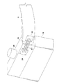
図1ないし図4はこの発明の一実施例に係り、図1は実施例に係る外科用X線TV装置の概略構成を示す斜視図であり、図2はX線管装置の縦断面図であり、図3は伝熱部の外観斜視図であり、図4はヒートパイプの取付構造を示した分解斜視図である。
【0022】
実施例に係る外科用X線TV装置1は、被検体が載置されるベッド3とベースユニット5とを備えている。ベッド3は、床面に固定あるいは半固定で設置されている。ベースユニット5は、ベッド3の側方に配置され、電源装置や制御ユニット等を内蔵し、床面を移動可能に構成されている。
【0023】
ベースユニット5は、鉛直軸周りの回転軸を有する支柱7を上部に備えている。この支柱7の上部には、先端部側でCアーム9を保持する支持アーム11の基端部側が取り付けられている。支持アーム11は、その先端部で、図中に二点鎖線で示す方向にCアーム9を回動可能に保持する。
【0024】
Cアーム9の一端側には、X線管装置13が取り付けられ、対向位置には撮像部15が取り付けられている。撮像部15は、イメージインテンシファイアやX線フラットパネル検出器などの透過X線を可視化する機能を備えている。
【0025】
なお、X線管装置13の上部と、Cアーム9のうちX線管装置13側の先端部の一部とは、メンテナンス性等を考慮して樹脂製のカバー17によって覆われている。
【0026】
図2を参照する。
このX線管装置13は、外科用としてコンパクト化されたモノタンク式と呼ばれているものである。ハウジング19には絶縁油が充填されているとともに、固定陽極X線管21と、高圧トランス23と、フィラメント用トランス25とが内蔵されている。
【0027】
固定陽極X線管21は、内部が高真空にされたガラスバルブ27に、フィラメント用トランス25からの高電圧が印加される陰極(フィラメント)29と、高圧トランス23に接続された固定陽極(ターゲット)31を備えている。固定陽極31は、その後端部からガラスバルブ27の外部に導出された冷却フィン33を備えている。
【0028】
高圧トランス23及びフィラメント用トランス25が撮影者の所望する管電圧・管電流に応じて作動すると、陰極29で発生した熱電子は、高電圧によって加速されて図中に点線で示すように、固定陽極31の先端傾斜面に衝突して、図中に二点鎖線で示す方向にX線を発生する。発生したX線は、ハウジング19の上面に立設された放射部20を介して撮像部15側に照射される。このときX線管装置13に対して供給されたエネルギは、その99%以上が熱に変化する。この熱は、冷却フィン33から放出され、絶縁油の対流によってハウジング19に伝達されたり、ハウジング19に連結されたCアーム9に伝達されたりしてその周囲に放出される。
【0029】
図3を参照する。
ハウジング19の上部側面と、Cアーム9の先端部には、伝熱部35が取り付けられている。なお、図示していないが、図3におけるハウジング19の反対側の側面にも伝熱部35が取り付けられている。
【0030】
この伝熱部35は、図4に示すようにして構成されているとともに取り付けられている。
【0031】
ヒートパイプ37は、細長い棒状を呈した一般的に使用されるものであり、この例では3本のヒートパイプ37を用いている。ヒートパイプ37の両端部には、矩形状の接続部材39が接着剤Pによって固定されている。接着剤としては、熱伝導性に優れ、かつ固着時における強度を有するものが好ましく、例えば、半田が利用可能である。接着剤Pは、ヒートパイプ37の円弧状の外周面と接続部材39の表面を埋めるので、接続材料39とヒートパイプ37との接触面積を増やして熱伝導性を高めることができる。
【0032】
接続部材39にはネジ穴41が形成されており、取付ネジ43によってハウジング19及びCアーム9に取り付けられる。その際に、接続部材39とハウジング19及びCアーム9との間には、伝熱材料44を挟み込んでおくことが好ましい。
【0033】
伝熱材料44としては、弾性を有する紙状の伝熱シートや、CPUパッケージとその上面に取り付ける冷却ユニットとの間に塗布する粘性を有するペースト等が例示される。ハウジング19、Cアーム9、接続部材39は全て金属であるので、互いに接触させても空気層が介在すること等により密着度は低い。そこで、熱伝導率が高い伝熱材料44を介在させることにより、それらとの密着性を高めることによって伝熱部35の熱伝導率をより高めることができる。
【0034】
なお、伝熱部35のX線管装置13側の接続部材39は、ハウジング19の側面中、冷却フィン33に近い位置に取り付けるのが放熱効率の観点から好ましい。
【0035】
上記のように構成した外科用X線TV装置1は、銅の100倍以上の熱伝導率を有するヒートパイプ37の両端をハウジング19とCアーム9に取り付けるので、ハウジング19の熱をX線管装置13よりも熱容量が大なるCアーム9に対してヒートパイプ37を通して効率的に伝達することができる。
【0036】
ところで、X線管装置13は、絶縁油の温度が上がり過ぎると、絶縁油が膨張してハウジング19の内圧が過度に高まって危険であるので、ハウジング19内に設けられたサーマルスイッチ(図示省略)が絶縁油の温度を検知し、その温度が所定値(例えば、60,70℃)に達した場合には、X線管装置13の動作を停止させる安全機構を備えている。その関係上、ハウジング19内の絶縁油の温度が急上昇した場合には、上記の安全機構が作動してX線が停止してしまい、長時間にわたる動作ができなくなって診断・手術等に支障をきたすことがある。
【0037】
しかし、この実施例装置によると、ハウジング19からCアーム9への熱伝導をヒートパイプ37によって積極的に行うことで高効率化しているので、X線管装置13の温度上昇を抑制することができる。したがって、上記の安全機構が作動する程の温度上昇を防止することができるので、外科用X線TV装置1を長時間にわたって動作させることが可能となる。
【0038】
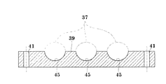
なお、上記の接続部材39は、図5に示すように構成するのが好ましい。
【0039】
すなわち、接続部材39のうちヒートパイプ37の取付面側に、ヒートパイプ37の外周面形状に応じた凹部45を設けるのである。図5は、ヒートパイプ37の外周面が円形状を呈する場合の例であるが、外周面(縦断面)が矩形状を呈する場合にはそれに応じた形状とすればよい。
【0040】
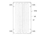
また、上記の例では、細長棒状のヒートパイプ37を例に採って説明したが、図6に示すような形状の特殊なヒートパイプ37Aを採用してもよい。
【0041】
すなわち、このヒートパイプ37Aは、ジグザグ状の一本の管47が板状の筐体49に形成され、かつ筐体49の一端側から他端側に形成されているものである(蛇行細管ヒートパイプとも呼ばれる)。筐体49の両端部には、ネジ穴41Aを設けておく。このような特殊なタイプのヒートパイプ37Aの場合には、単純な構造であるので、ハウジング19及びCアーム9の側面への取付が簡単にできる。
【0042】
なお、この発明は上述した実施例に限定されるものではなく、以下のように変形実施が可能である。
【0043】
(1)上記の実施例では、3本のヒートパイプ37を伝熱部35に設けているが、放熱をさらに高めたい場合には4本以上のヒートパイプを設けてもよい。逆に放熱に余裕がある場合には、2本以下のヒートパイプを用いてもよい。
【0044】
(2)ヒートパイプ37を接続部材39を介して取り付けることなく、直接的にX線管装置19及びCアーム9に取り付けるようにしてもよい。
【0045】
(3)接続部材39とX線管装置19及びCアーム9の熱伝導的にみた密着度が十分に高い場合には、伝熱材料44を用いる必要はない。
【0046】
(4)上記の実施例では、カバー17がX線管装置13に取り付けられている関係上、X線管装置13の側面にのみ伝熱部35を取り付けているが、それ以外の部分に伝熱部35をさらに取り付けるようにしてもよい。例えば、ハウジング19の後面(図3の右手前側面)と、Cアーム9の下面(図3の図示されていない面)とにわたって取り付ける。
【0047】
(5)上記の実施例に係る外科用X線TV装置1は、X線管装置13と撮像部15とをCアーム9で対向支持した形態を採用しているが、この発明はCアーム9で支持する装置に限定されるものではなく、例えば、Uの字状を呈するアームなどの種々のアームを備える外科用X線TV装置1に適用することができる。
【0048】
【発明の効果】
以上の説明から明らかなように、この発明によれば、ヒートパイプの両端をハウジングとアームに取り付けるので、ハウジングの熱をX線管装置よりも熱容量が大なるアームに対してヒートパイプを通して効率的に伝達することができる。したがって、ハウジングからアームへの熱伝導を高効率化できるので、X線管装置の温度上昇を抑制することができ、長時間にわたる動作を行わせることが可能となる。
【図面の簡単な説明】
【図1】実施例に係る外科用X線TV装置の概略構成を示す斜視図である。
【図2】X線管装置の縦断面図である。
【図3】伝熱部の外観斜視図である。
【図4】ヒートパイプの取付構造を示した分解斜視図である。
【図5】取付部材の好ましい例を示す縦断面図である。
【図6】ヒートパイプの変形例を示す平面図である。
【符号の説明】
1 … 外科用X線TV装置
3 … ベッド
9 … Cアーム
13 … X線管装置
15 … 撮像部
17 … カバー
19 … ハウジング
21 … 固定陽極X線管
23 … 高圧トランス
25 … フィラメント用トランス
27 … ガラスバルブ
29 … 陰極
31 … 固定陽極
35 … 伝熱部
37 … ヒートパイプ
39 … 接続部材39
P … 接着剤
44 … 伝熱材料
45 … 凹部[0001]
TECHNICAL FIELD OF THE INVENTION
The present invention relates to a surgical X-ray TV apparatus for supporting an imaging means such as an image intensifier or an X-ray flat panel detector and an X-ray tube apparatus so as to perform fluoroscopic imaging at the time of surgery. The present invention relates to a heat radiation technique for an X-ray tube device having a fixed anode type X-ray tube built in a housing.
[0002]
[Prior art]
X-ray tube apparatuses are roughly classified into a rotary anode type and a fixed anode type. The rotating anode type is widely used mainly in an apparatus that involves X-ray imaging because it can withstand a large instantaneous load. On the other hand, the fixed anode type has a relatively small instantaneous load, but has been used for a relatively long time. This fixed anode type is used, for example, in a surgical X-ray TV apparatus for performing fluoroscopic imaging during an operation.
[0003]
An X-ray tube apparatus provided with a fixed anode type X-ray tube, which is called a monotank type compact for surgical use, has, for example, the following configuration (Japanese Patent Application Laid-Open No. Hei 5-242992).
[0004]
A fixed anode type X-ray tube having a cathode (filament) and a fixed anode (target) opposed to each other in a glass bulb in a high vacuum state, a high voltage transformer for applying a high voltage, and a filament power supply Are housed in one housing filled with insulating oil.
[0005]
Thermions generated at the cathode (filament) are accelerated by the high voltage and collide with the fixed anode to generate X-rays. At this time, 99% or more of the energy supplied to the fixed anode type X-ray tube is converted to heat. In order to release this heat to the outside, a cooling fin is attached to one end of the fixed anode led out of the glass bulb. Heat generated at the fixed anode is transmitted to the insulating oil via the cooling fins, and further transmitted to the housing by convection of the insulating oil. The heat transmitted into the housing is released from the housing to the outside air or transmitted to an arm that connects and supports the housing.
[0006]
As described above, natural heat radiation is performed without using a cooling fan or the like because a surgical X-ray TV device is used during surgery. That is, when the cooling is performed by the cooling fan, dust is wound up, which is inappropriate in a surgical operating room requiring a clean environment.
[0007]
It is also conceivable to attach cooling fins to the housing without using a fan, but this is also not practical in the case of surgical use because maintenance for wiping blood or the like after surgery becomes complicated.
[0008]
[Problems to be solved by the invention]
However, the conventional example having such a configuration has the following problem.
That is, in the conventional apparatus, the X-ray intensity may be increased (increase the load on the X-ray tube apparatus) in order to improve the image quality of the fluoroscopic image, depending on the size of the fluoroscopic target region and the like. The conventional X-ray tube apparatus has a problem that heat generated under a large load cannot be quickly released due to the convection of insulating oil and natural heat radiation through the housing and the arm.
[0009]
By the way, in the conventional X-ray tube device, when the temperature of the insulating oil rises too much, the insulating oil expands and the internal pressure of the housing becomes excessively high, which is dangerous.
[0010]
Therefore, a thermal switch is provided in the housing, and a safety mechanism is provided for stopping the operation of the X-ray tube device when the temperature of the insulating oil reaches a predetermined value (for example, 60 or 70 ° C.). Have been. For this reason, if the temperature of the insulating oil in the housing rises sharply, the above-mentioned safety mechanism is activated and the X-ray is stopped, so that the operation cannot be performed for a long period of time, which hinders diagnosis and surgery. Sometimes.
[0011]
The present invention has been made in view of the above circumstances, and a surgical X-ray capable of operating for a long time by suppressing the temperature rise of the X-ray tube device by increasing the efficiency of heat conduction. It is intended to provide a TV device.
[0012]
[Means for Solving the Problems]
The present invention has the following configuration to achieve such an object.
[0013]
That is, according to the first aspect of the present invention, there is provided a surgical X-ray apparatus including a fixed anode type X-ray tube in a housing filled with insulating oil, and a surgical X-ray including an arm for supporting an imaging unit in opposition. In the linear TV device, both ends of a heat pipe are attached to the housing and the arm.
[0014]
(Action / Effect)
Attach both ends of a heat pipe having a thermal conductivity 100 times or more that of copper to the housing and the arm. Thereby, the heat of the housing to which the heat from the fixed anode type X-ray tube has been transmitted can be efficiently transmitted through the heat pipe to the arm having a larger heat capacity than the X-ray tube device. Therefore, the efficiency of heat conduction from the housing to the arm can be increased, so that the temperature rise of the X-ray tube device can be suppressed, and the operation can be performed for a long time.
[0015]
Further, in the surgical X-ray TV device according to
[0016]
(Action / Effect)
Since the heat pipe generally has a circular cross section, the contact area with the housing or the arm is small. Therefore, by attaching the heat pipe via a connecting member having a concave portion along the outer shape of the heat pipe, the contact area can be increased, so that heat can be efficiently transmitted.
[0017]
Note that the space between the arc portion of the heat pipe and the connection member may be filled with a heat conductive material (for example, a solder material) without providing the concave portion.
[0018]
Further, in the surgical X-ray TV apparatus according to claim 2, it is preferable that the connection member is attached via an elastic or viscous heat radiation material (claim 3).
[0019]
(Action / Effect)
Since the housing, the arm, and the connecting member are all made of metal, even if they come into contact with each other, the degree of adhesion is low due to the intervening air layer. Therefore, by interposing a heat transfer material having a high heat conductivity, it is possible to further increase the heat conductivity while improving the adhesion.
[0020]
Examples of the heat transfer material include a heat dissipation sheet (elastic sheet) and a heat dissipation paste (viscous paste).
[0021]
BEST MODE FOR CARRYING OUT THE INVENTION
An embodiment of the present invention will be described below with reference to the drawings.
1 to 4 relate to an embodiment of the present invention. FIG. 1 is a perspective view showing a schematic configuration of a surgical X-ray TV apparatus according to the embodiment, and FIG. 2 is a longitudinal sectional view of an X-ray tube apparatus. FIG. 3 is an external perspective view of the heat transfer section, and FIG. 4 is an exploded perspective view showing a heat pipe mounting structure.
[0022]
The surgical
[0023]
The base unit 5 has a
[0024]
An
[0025]
The upper part of the
[0026]
Please refer to FIG.
The
[0027]
The fixed
[0028]
When the
[0029]
Please refer to FIG.
A
[0030]
The
[0031]
The
[0032]
A
[0033]
Examples of the
[0034]
The
[0035]
In the surgical
[0036]
Incidentally, if the temperature of the insulating oil is too high, the insulating oil expands and the internal pressure of the
[0037]
However, according to the apparatus of this embodiment, since the heat is efficiently transmitted from the
[0038]
Preferably, the connecting
[0039]
That is, the
[0040]
Further, in the above-described example, the
[0041]
That is, this
[0042]
The present invention is not limited to the above-described embodiment, but can be modified as follows.
[0043]
(1) In the above embodiment, three
[0044]
(2) The
[0045]
(3) If the
[0046]
(4) In the above embodiment, since the
[0047]
(5) The surgical
[0048]
【The invention's effect】
As is clear from the above description, according to the present invention, since both ends of the heat pipe are attached to the housing and the arm, the heat of the housing can be efficiently passed through the heat pipe to the arm having a larger heat capacity than the X-ray tube device. Can be transmitted to. Therefore, the efficiency of heat conduction from the housing to the arm can be increased, so that the temperature rise of the X-ray tube device can be suppressed, and the operation can be performed for a long time.
[Brief description of the drawings]
FIG. 1 is a perspective view showing a schematic configuration of a surgical X-ray TV apparatus according to an embodiment.
FIG. 2 is a longitudinal sectional view of the X-ray tube device.
FIG. 3 is an external perspective view of a heat transfer unit.
FIG. 4 is an exploded perspective view showing a mounting structure of the heat pipe.
FIG. 5 is a longitudinal sectional view showing a preferred example of a mounting member.
FIG. 6 is a plan view showing a modification of the heat pipe.
[Explanation of symbols]
DESCRIPTION OF
P: adhesive 44: heat transfer material 45: recess
Claims (3)
Priority Applications (1)
| Application Number | Priority Date | Filing Date | Title |
|---|---|---|---|
| JP2002321138A JP2004154236A (en) | 2002-11-05 | 2002-11-05 | Surgical x-ray tv device |
Applications Claiming Priority (1)
| Application Number | Priority Date | Filing Date | Title |
|---|---|---|---|
| JP2002321138A JP2004154236A (en) | 2002-11-05 | 2002-11-05 | Surgical x-ray tv device |
Publications (1)
| Publication Number | Publication Date |
|---|---|
| JP2004154236A true JP2004154236A (en) | 2004-06-03 |
Family
ID=32801787
Family Applications (1)
| Application Number | Title | Priority Date | Filing Date |
|---|---|---|---|
| JP2002321138A Pending JP2004154236A (en) | 2002-11-05 | 2002-11-05 | Surgical x-ray tv device |
Country Status (1)
| Country | Link |
|---|---|
| JP (1) | JP2004154236A (en) |
Cited By (4)
| Publication number | Priority date | Publication date | Assignee | Title |
|---|---|---|---|---|
| JP2004358211A (en) * | 2003-05-14 | 2004-12-24 | Shimadzu Corp | Surgical x-ray tv apparatus |
| JP2007005283A (en) * | 2005-02-21 | 2007-01-11 | Hitachi Medical Corp | Integrated x-ray generator |
| JP2012011066A (en) * | 2010-07-02 | 2012-01-19 | Asahi Roentgen Kogyo Kk | X-ray tube container |
| JP2014078474A (en) * | 2012-10-12 | 2014-05-01 | Origin Electric Co Ltd | Integrated x-ray generation device |
Citations (12)
| Publication number | Priority date | Publication date | Assignee | Title |
|---|---|---|---|---|
| JPS5745910U (en) * | 1980-09-01 | 1982-03-13 | ||
| JPS5839691Y2 (en) * | 1980-02-19 | 1983-09-07 | 株式会社 日立メデイコ | surgical x-ray television equipment |
| JPS61183861A (en) * | 1985-02-08 | 1986-08-16 | Hitachi Medical Corp | X-ray tube device |
| JPS6291397U (en) * | 1985-11-27 | 1987-06-11 | ||
| JPH07194587A (en) * | 1994-01-10 | 1995-08-01 | Toshiba Corp | X-ray ct system |
| JPH11271456A (en) * | 1998-03-23 | 1999-10-08 | Toshiba Corp | Plane detector |
| JP2000258541A (en) * | 1999-03-11 | 2000-09-22 | Toshiba Corp | Radiation-detecting device |
| JP3168760B2 (en) * | 1993-02-26 | 2001-05-21 | 株式会社島津製作所 | Fixed anode X-ray tube device |
| JP2001319606A (en) * | 1999-12-27 | 2001-11-16 | General Electric Co <Ge> | Vapor-chamber target for x-ray tube |
| JP2002034968A (en) * | 2000-07-25 | 2002-02-05 | Toshiba Corp | X-ray ct apparatus |
| JP2002075689A (en) * | 2000-05-04 | 2002-03-15 | Ge Medical Systems Global Technology Co Llc | Hv connector having heat transmitting equipment for x-ray tube |
| JP3339887B2 (en) * | 1991-09-03 | 2002-10-28 | ジェネラル エレクトリック セージェーエール ソシエテ アノニム | X-ray apparatus having high-voltage power supply device mounted in casing |
-
2002
- 2002-11-05 JP JP2002321138A patent/JP2004154236A/en active Pending
Patent Citations (12)
| Publication number | Priority date | Publication date | Assignee | Title |
|---|---|---|---|---|
| JPS5839691Y2 (en) * | 1980-02-19 | 1983-09-07 | 株式会社 日立メデイコ | surgical x-ray television equipment |
| JPS5745910U (en) * | 1980-09-01 | 1982-03-13 | ||
| JPS61183861A (en) * | 1985-02-08 | 1986-08-16 | Hitachi Medical Corp | X-ray tube device |
| JPS6291397U (en) * | 1985-11-27 | 1987-06-11 | ||
| JP3339887B2 (en) * | 1991-09-03 | 2002-10-28 | ジェネラル エレクトリック セージェーエール ソシエテ アノニム | X-ray apparatus having high-voltage power supply device mounted in casing |
| JP3168760B2 (en) * | 1993-02-26 | 2001-05-21 | 株式会社島津製作所 | Fixed anode X-ray tube device |
| JPH07194587A (en) * | 1994-01-10 | 1995-08-01 | Toshiba Corp | X-ray ct system |
| JPH11271456A (en) * | 1998-03-23 | 1999-10-08 | Toshiba Corp | Plane detector |
| JP2000258541A (en) * | 1999-03-11 | 2000-09-22 | Toshiba Corp | Radiation-detecting device |
| JP2001319606A (en) * | 1999-12-27 | 2001-11-16 | General Electric Co <Ge> | Vapor-chamber target for x-ray tube |
| JP2002075689A (en) * | 2000-05-04 | 2002-03-15 | Ge Medical Systems Global Technology Co Llc | Hv connector having heat transmitting equipment for x-ray tube |
| JP2002034968A (en) * | 2000-07-25 | 2002-02-05 | Toshiba Corp | X-ray ct apparatus |
Cited By (4)
| Publication number | Priority date | Publication date | Assignee | Title |
|---|---|---|---|---|
| JP2004358211A (en) * | 2003-05-14 | 2004-12-24 | Shimadzu Corp | Surgical x-ray tv apparatus |
| JP2007005283A (en) * | 2005-02-21 | 2007-01-11 | Hitachi Medical Corp | Integrated x-ray generator |
| JP2012011066A (en) * | 2010-07-02 | 2012-01-19 | Asahi Roentgen Kogyo Kk | X-ray tube container |
| JP2014078474A (en) * | 2012-10-12 | 2014-05-01 | Origin Electric Co Ltd | Integrated x-ray generation device |
Similar Documents
| Publication | Publication Date | Title |
|---|---|---|
| JP6039282B2 (en) | Radiation generator and radiation imaging apparatus | |
| JP6039283B2 (en) | Radiation generator and radiation imaging apparatus | |
| US8428221B2 (en) | Medical x-ray acquisition system | |
| JP3275797B2 (en) | Low pressure mercury vapor discharge lamp | |
| WO2015185003A1 (en) | Collimation modulatable x-ray generator | |
| JP2001143646A (en) | Method of cooling x ray tube with rotary anode assembly by means of heat pipe | |
| JP2007080568A (en) | X-ray generation device | |
| US20150010131A1 (en) | X-ray apparatus and x-ray image diagnostic apparatus | |
| JP4223863B2 (en) | X-ray generator | |
| JP5414167B2 (en) | X-ray tube device | |
| JP2004154236A (en) | Surgical x-ray tv device | |
| EP2748834A1 (en) | X-ray tube with heatable field emission electron emitter and method for operating same | |
| JP2004358211A (en) | Surgical x-ray tv apparatus | |
| WO2007026612A1 (en) | X-ray tube | |
| JP3168760B2 (en) | Fixed anode X-ray tube device | |
| JP2003123999A (en) | X-ray tube device | |
| JP4294447B2 (en) | Infrared bulb and heating device | |
| JP2006344445A (en) | X-ray tube device and x-ray ct device using the same | |
| US6608429B1 (en) | X-ray imaging system with convective heat transfer device | |
| JP2002367797A (en) | X-ray tube device | |
| JP2011062240A (en) | X-ray equipment | |
| CN109124548A (en) | Has the fujinon electronic video endoscope being well heat-treated | |
| JP2007042434A (en) | X-ray tube | |
| JP2004215741A (en) | X-ray ct equippment and heat dissipation system thereof | |
| JP2008226783A (en) | X-ray generator, and x-ray device |
Legal Events
| Date | Code | Title | Description |
|---|---|---|---|
| A621 | Written request for application examination |
Free format text: JAPANESE INTERMEDIATE CODE: A621 Effective date: 20050202 |
|
| A977 | Report on retrieval |
Free format text: JAPANESE INTERMEDIATE CODE: A971007 Effective date: 20080207 |
|
| A131 | Notification of reasons for refusal |
Free format text: JAPANESE INTERMEDIATE CODE: A131 Effective date: 20080226 |
|
| A521 | Request for written amendment filed |
Free format text: JAPANESE INTERMEDIATE CODE: A523 Effective date: 20080424 |
|
| A131 | Notification of reasons for refusal |
Free format text: JAPANESE INTERMEDIATE CODE: A131 Effective date: 20080603 |
|
| A02 | Decision of refusal |
Free format text: JAPANESE INTERMEDIATE CODE: A02 Effective date: 20081014 |