JP2004152762A - Solid oxide fuel cell having gas channel - Google Patents
Solid oxide fuel cell having gas channel Download PDFInfo
- Publication number
- JP2004152762A JP2004152762A JP2003364800A JP2003364800A JP2004152762A JP 2004152762 A JP2004152762 A JP 2004152762A JP 2003364800 A JP2003364800 A JP 2003364800A JP 2003364800 A JP2003364800 A JP 2003364800A JP 2004152762 A JP2004152762 A JP 2004152762A
- Authority
- JP
- Japan
- Prior art keywords
- electrolyte
- solid oxide
- fuel cell
- support
- gas channel
- Prior art date
- Legal status (The legal status is an assumption and is not a legal conclusion. Google has not performed a legal analysis and makes no representation as to the accuracy of the status listed.)
- Pending
Links
Images


Classifications
-
- H—ELECTRICITY
- H01—ELECTRIC ELEMENTS
- H01M—PROCESSES OR MEANS, e.g. BATTERIES, FOR THE DIRECT CONVERSION OF CHEMICAL ENERGY INTO ELECTRICAL ENERGY
- H01M8/00—Fuel cells; Manufacture thereof
- H01M8/10—Fuel cells with solid electrolytes
- H01M8/12—Fuel cells with solid electrolytes operating at high temperature, e.g. with stabilised ZrO2 electrolyte
- H01M8/124—Fuel cells with solid electrolytes operating at high temperature, e.g. with stabilised ZrO2 electrolyte characterised by the process of manufacturing or by the material of the electrolyte
- H01M8/1246—Fuel cells with solid electrolytes operating at high temperature, e.g. with stabilised ZrO2 electrolyte characterised by the process of manufacturing or by the material of the electrolyte the electrolyte consisting of oxides
-
- H—ELECTRICITY
- H01—ELECTRIC ELEMENTS
- H01M—PROCESSES OR MEANS, e.g. BATTERIES, FOR THE DIRECT CONVERSION OF CHEMICAL ENERGY INTO ELECTRICAL ENERGY
- H01M8/00—Fuel cells; Manufacture thereof
- H01M8/02—Details
-
- H—ELECTRICITY
- H01—ELECTRIC ELEMENTS
- H01M—PROCESSES OR MEANS, e.g. BATTERIES, FOR THE DIRECT CONVERSION OF CHEMICAL ENERGY INTO ELECTRICAL ENERGY
- H01M8/00—Fuel cells; Manufacture thereof
- H01M8/10—Fuel cells with solid electrolytes
- H01M8/12—Fuel cells with solid electrolytes operating at high temperature, e.g. with stabilised ZrO2 electrolyte
- H01M8/1213—Fuel cells with solid electrolytes operating at high temperature, e.g. with stabilised ZrO2 electrolyte characterised by the electrode/electrolyte combination or the supporting material
- H01M8/1226—Fuel cells with solid electrolytes operating at high temperature, e.g. with stabilised ZrO2 electrolyte characterised by the electrode/electrolyte combination or the supporting material characterised by the supporting layer
-
- H—ELECTRICITY
- H01—ELECTRIC ELEMENTS
- H01M—PROCESSES OR MEANS, e.g. BATTERIES, FOR THE DIRECT CONVERSION OF CHEMICAL ENERGY INTO ELECTRICAL ENERGY
- H01M8/00—Fuel cells; Manufacture thereof
- H01M8/10—Fuel cells with solid electrolytes
- H01M8/12—Fuel cells with solid electrolytes operating at high temperature, e.g. with stabilised ZrO2 electrolyte
- H01M8/124—Fuel cells with solid electrolytes operating at high temperature, e.g. with stabilised ZrO2 electrolyte characterised by the process of manufacturing or by the material of the electrolyte
- H01M8/1246—Fuel cells with solid electrolytes operating at high temperature, e.g. with stabilised ZrO2 electrolyte characterised by the process of manufacturing or by the material of the electrolyte the electrolyte consisting of oxides
- H01M8/1253—Fuel cells with solid electrolytes operating at high temperature, e.g. with stabilised ZrO2 electrolyte characterised by the process of manufacturing or by the material of the electrolyte the electrolyte consisting of oxides the electrolyte containing zirconium oxide
-
- H—ELECTRICITY
- H01—ELECTRIC ELEMENTS
- H01M—PROCESSES OR MEANS, e.g. BATTERIES, FOR THE DIRECT CONVERSION OF CHEMICAL ENERGY INTO ELECTRICAL ENERGY
- H01M8/00—Fuel cells; Manufacture thereof
- H01M8/10—Fuel cells with solid electrolytes
- H01M8/12—Fuel cells with solid electrolytes operating at high temperature, e.g. with stabilised ZrO2 electrolyte
- H01M8/124—Fuel cells with solid electrolytes operating at high temperature, e.g. with stabilised ZrO2 electrolyte characterised by the process of manufacturing or by the material of the electrolyte
- H01M8/1246—Fuel cells with solid electrolytes operating at high temperature, e.g. with stabilised ZrO2 electrolyte characterised by the process of manufacturing or by the material of the electrolyte the electrolyte consisting of oxides
- H01M8/126—Fuel cells with solid electrolytes operating at high temperature, e.g. with stabilised ZrO2 electrolyte characterised by the process of manufacturing or by the material of the electrolyte the electrolyte consisting of oxides the electrolyte containing cerium oxide
-
- H—ELECTRICITY
- H01—ELECTRIC ELEMENTS
- H01M—PROCESSES OR MEANS, e.g. BATTERIES, FOR THE DIRECT CONVERSION OF CHEMICAL ENERGY INTO ELECTRICAL ENERGY
- H01M8/00—Fuel cells; Manufacture thereof
- H01M8/10—Fuel cells with solid electrolytes
- H01M8/12—Fuel cells with solid electrolytes operating at high temperature, e.g. with stabilised ZrO2 electrolyte
- H01M8/124—Fuel cells with solid electrolytes operating at high temperature, e.g. with stabilised ZrO2 electrolyte characterised by the process of manufacturing or by the material of the electrolyte
- H01M8/1246—Fuel cells with solid electrolytes operating at high temperature, e.g. with stabilised ZrO2 electrolyte characterised by the process of manufacturing or by the material of the electrolyte the electrolyte consisting of oxides
- H01M8/1266—Fuel cells with solid electrolytes operating at high temperature, e.g. with stabilised ZrO2 electrolyte characterised by the process of manufacturing or by the material of the electrolyte the electrolyte consisting of oxides the electrolyte containing bismuth oxide
-
- Y—GENERAL TAGGING OF NEW TECHNOLOGICAL DEVELOPMENTS; GENERAL TAGGING OF CROSS-SECTIONAL TECHNOLOGIES SPANNING OVER SEVERAL SECTIONS OF THE IPC; TECHNICAL SUBJECTS COVERED BY FORMER USPC CROSS-REFERENCE ART COLLECTIONS [XRACs] AND DIGESTS
- Y02—TECHNOLOGIES OR APPLICATIONS FOR MITIGATION OR ADAPTATION AGAINST CLIMATE CHANGE
- Y02E—REDUCTION OF GREENHOUSE GAS [GHG] EMISSIONS, RELATED TO ENERGY GENERATION, TRANSMISSION OR DISTRIBUTION
- Y02E60/00—Enabling technologies; Technologies with a potential or indirect contribution to GHG emissions mitigation
- Y02E60/30—Hydrogen technology
- Y02E60/50—Fuel cells
-
- Y—GENERAL TAGGING OF NEW TECHNOLOGICAL DEVELOPMENTS; GENERAL TAGGING OF CROSS-SECTIONAL TECHNOLOGIES SPANNING OVER SEVERAL SECTIONS OF THE IPC; TECHNICAL SUBJECTS COVERED BY FORMER USPC CROSS-REFERENCE ART COLLECTIONS [XRACs] AND DIGESTS
- Y02—TECHNOLOGIES OR APPLICATIONS FOR MITIGATION OR ADAPTATION AGAINST CLIMATE CHANGE
- Y02P—CLIMATE CHANGE MITIGATION TECHNOLOGIES IN THE PRODUCTION OR PROCESSING OF GOODS
- Y02P70/00—Climate change mitigation technologies in the production process for final industrial or consumer products
- Y02P70/50—Manufacturing or production processes characterised by the final manufactured product
Abstract
Description
本発明はガスチャンネルを有する固体酸化物燃料電池に関する。より詳しくは、本発明は四つの端部又は対向する二つの端部の断面が∩字型に下向き折曲している電極支持体型又は電解質支持体型であり、かつその内部及び/又は外部にガスチャンネルを有する固体酸化物燃料電池に関する。 The present invention relates to a solid oxide fuel cell having gas channels. More specifically, the present invention is an electrode support type or electrolyte support type in which the cross section of four ends or two opposing ends is bent downward in a ∩ shape, and a gas is provided inside and / or outside thereof. The present invention relates to a solid oxide fuel cell having a channel.
一般的に、燃料電池は、陰極と陽極に燃料ガスと空気が注入され、それぞれに電気化学反応が起ることによって、電解質によるイオン伝導が進行され、外部回路による電子伝導が進行される、つまり、電極及び電解質特性に符合する条件下で、燃料と空気注入が維持される限り、続けて電気を得ることのできるエネルギー発生装置である。 Generally, in a fuel cell, a fuel gas and air are injected into a cathode and an anode, and an electrochemical reaction occurs in each of them, whereby ion conduction by an electrolyte proceeds and electron conduction by an external circuit proceeds, that is, , An energy generator capable of continuously obtaining electricity as long as fuel and air injection are maintained under conditions corresponding to electrode and electrolyte characteristics.
燃料電池は高効率の発電方式で、公害物質の排出が非常に少ないという長所を持っており、使用する電解質の種類によって、作動温度、電極材料、及び応用分野などが多様である。 A fuel cell is a high-efficiency power generation system and has the advantage of emitting very little pollutant. The operating temperature, electrode materials, and application fields vary depending on the type of electrolyte used.
この中、第3世代の燃料電池というべき固体酸化物燃料電池(Solid Oxide Fuel Cell:SOFC)とは、単電池(End Cell)の両電極面へ反応ガスが円滑に流れるようにすると同時に、分離板との電気的接触及び2種の反応ガス間の気密を維持することによって、緻密な固体電解質層への酸素又は水素イオン伝導現象を誘導し、これにより、電極層で電気化学反応により発生する起電力を発電に用いる装置である。 Among them, a solid oxide fuel cell (SOFC), which is a third-generation fuel cell, allows a reaction gas to flow smoothly to both electrode surfaces of a unit cell (End Cell) and simultaneously separates the reaction gas. By maintaining electrical contact with the plate and hermeticity between the two reaction gases, an oxygen or hydrogen ion conduction phenomenon to the dense solid electrolyte layer is induced, thereby generating an electrochemical reaction in the electrode layer. This device uses electromotive force for power generation.
特に、SOFCは、熱化学的に安定した金属化合物を電解質として用い、これに燃料極と空気極を付着した形態で、水素、メタン、プロパン、ブタンなどの燃料ガスのいずれを用いても良く、酸化剤として空気或いは酸素を利用できる高効率・低公害の発電方式である。 In particular, the SOFC uses a thermochemically stable metal compound as an electrolyte, and in a form in which a fuel electrode and an air electrode are attached to the electrolyte, any of hydrogen, methane, propane, and butane may be used as a fuel gas. This is a high-efficiency, low-pollution power generation system that can use air or oxygen as an oxidant.
これまで広く知られている固体酸化物燃料電池の材料においては、燃料極としてNiとYSZサーメットの混合物を、電解質としてジルコニア(ZrO2+8Y2O3)系、セリアー(CeO2)系、ビスムス酸化物(Bi2O3)系、ペロブスカイト(perovskite)系のうち、1つあるいはその以上の粉末を、空気極としてLaSrMnO3(LSM)を、分離板又は接続子(interconnector)としてCr−5Fe−1Y2O3、Ni base metal、ステーンレススチール、LaSrCrO3を、集電体及び封止材としてガラス又はガラス−セラミックスを用いており、これらを互いに積層してスタック(stack)を構成し、他の周辺装置と結合させて全体発電システムを構成している。 In the materials of solid oxide fuel cells which have been widely known so far, a mixture of Ni and YSZ cermet is used as a fuel electrode, a zirconia (ZrO 2 + 8Y 2 O 3 ) system, a ceria (CeO 2 ) system, and a bismuth oxide are used as an electrolyte. (Bi 2 O 3 ) -based or perovskite-based powder, one or more powders, LaSrMnO 3 (LSM) as an air electrode, and Cr-5Fe-1Y as a separation plate or an interconnector (interconnector). 2 O 3 , Ni base metal, stainless steel, LaSrCrO 3 are used as a current collector and a sealing material using glass or glass-ceramics, and these are stacked on each other to form a stack. Combined with peripheral devices to form the entire power generation system
この際に使われる単電子は、電解質を間において一方には燃料極(陰極)、他方には空気極(陽極)を形成した形態で、それぞれの電極層で電気化学反応が容易に起るように、多孔性構造を有し、電解質に該当する中間層は、燃料ガスと酸化ガスが互いに通気しない緻密な構造を有する。 The single electron used at this time has a fuel electrode (cathode) formed on one side and an air electrode (anode) formed on the other side with an electrolyte in between, so that an electrochemical reaction easily occurs in each electrode layer. In addition, the intermediate layer having a porous structure and corresponding to the electrolyte has a dense structure in which the fuel gas and the oxidizing gas do not pass through each other.
一般的にSOFCには、単電池の形態によって、チューブ型と平板型が主に開発されており、この中チューブ型の方が先に開発され始めたが、製造方法が難しくいため、実質的に実用化するには問題があった。一方、添付の図1aに示すように、平板型では一般的に分離板8にて燃料ガスと酸化ガスを分離して単電池4に供給し、この際、分離板8においては、発生した電気がよく流れるように電気的に抵抗が小さくなければならない。
Generally, SOFCs are mainly developed in a tube type and a flat plate type depending on the form of a unit cell. Among them, the tube type is started to be developed first, but since the manufacturing method is difficult, it is substantially required. There were problems in putting it to practical use. On the other hand, as shown in FIG. 1A, in the case of a flat plate type, generally, a fuel gas and an oxidizing gas are separated by a
又、図1bに示すように、スタックを製作しようとする際には、平板型の単電池を分離板の間に載置し、分離板の両方のチャンネルに沿って流れる2種のガスが互いに交わらないように、封止材又は封止ガラスを用いて気密を維持すると共に、単電池の両電極層で円滑なガス供給が行われるようにしなければならない。特に、単電池と分離板が接触していない残りの部分は、気密性と絶縁性の特性を有する材料、例えば、セラミックス−ガラスで作られた絶縁層乃至は板状の形態でガス封止しなければならない。 Also, as shown in FIG. 1b, when a stack is to be manufactured, a flat cell is placed between separators, and two gases flowing along both channels of the separators do not cross each other. As described above, airtightness must be maintained by using a sealing material or a sealing glass, and a smooth gas supply must be performed between both electrode layers of the unit cell. In particular, the remaining portion where the unit cell and the separator are not in contact with each other is gas-sealed with a material having airtightness and insulating properties, for example, an insulating layer or plate made of ceramics-glass. There must be.
このような分離板の素材としては、金属とセラミックスの材料が広く使われており、特に、電気伝導性が優れており、かつガスの気密性を維持するに緻密な素材でなければならない。又、固体酸化物の燃料電池の作動温度である高温、例えば400乃至1000℃で耐酸化性を有しなければならない。なぜなら、燃料ガスである水素などは単電池の燃料極側の面(分離板における上面)、酸化剤である空気は単電池の空気極側の面(分離板における下面)に、分離板を間において、それぞれの反応ガスを分離して単電池に供給すると同時に、電気がよく流れるようにしなければならないためである。従って、加工が容易でなく、製作コストの高いセラミック材よりは金属材の分離板を使う方が、SOFC発電システムの常用化に有利である。しかし、高温であるほど又は運転時間が経過するほど、金属分離板の空気極側の表面に金属酸化が進み、これによって、スタックの性能が低下するため、耐久性においては不利である。 Metals and ceramics are widely used as materials for such a separating plate, and in particular, they must have excellent electrical conductivity and must be dense to maintain gas tightness. Further, it must have oxidation resistance at a high operating temperature of a solid oxide fuel cell, for example, 400 to 1000 ° C. This is because the fuel gas such as hydrogen is on the fuel electrode side surface of the unit cell (upper surface of the separator), and the oxidant air is on the unit cell air electrode side (lower surface of the separator). In this case, each reaction gas must be separated and supplied to the unit cell, and at the same time, electricity must flow well. Therefore, it is more advantageous to use a metal separation plate than to use a ceramic material which is not easy to process and has a high production cost, for commercializing an SOFC power generation system. However, the higher the temperature or the longer the operation time, the more the metal oxidation proceeds on the surface of the metal separator on the air electrode side, thereby lowering the performance of the stack, which is disadvantageous in durability.
従って、金属材分離板はセラミックス材とは異なって様々な形態への加工製作が容易であるという長所があるため、中温型(intermediate Temperature、約500〜850℃)のSOFCスタックを開発する際に、より広く使われている。しかし、金属材分離板の場合、SOFCが動作する温度で、単電池の熱膨張係数(おおよそ約10×10−6/℃)より1.2乃至2倍程度大きい値を有するため、SOFC発電装置をオン又はオフする際、つまり、常温から高温へ、或いは高温から常温への温度変化(つまり、熱サイクル)の際、より大きい熱応力が誘発するという短所がある。しかし、最近のSOFC技術は、より優れた性能の単電池が開発されるにつれて、より低い温度(中温型)でも、従来と同じ性能を得ることができるようになった。従って、セラミックス材よりは、金属材分離板の使用が頻繁になってきている状況である。 Therefore, unlike the ceramic material, the metal material separation plate has an advantage that it can be easily processed and formed into various forms. Therefore, when developing an intermediate temperature SOFC stack of about 500 to 850 ° C. , Is more widely used. However, in the case of the metal separator, the SOFC power generation device has a value that is about 1.2 to 2 times larger than the thermal expansion coefficient (approximately 10 × 10 −6 / ° C.) of the cell at the temperature at which the SOFC operates. There is a disadvantage in that when turning on or off, that is, when a temperature changes from normal temperature to high temperature or from high temperature to normal temperature (that is, thermal cycle), a larger thermal stress is induced. However, in recent SOFC technology, as cells with higher performance have been developed, the same performance can be obtained even at a lower temperature (medium temperature type). Therefore, the use of metal material separation plates is becoming more frequent than ceramic materials.
一方、金属材或いはセラミックス材や分離板の本来の用途は、ガスの流れと電気的接触であり、この中、注入反応ガスの円滑な流れのために、常にチャンネル構造を有している。特に、セラミックス材はプレス(Press)粉末成型(compaction)を行うため、製作工程が複雑ではないが、金属材分離板の場合は、プレス成型でなく主に加工成型(machining)で製作しているため、燃料電池の必須構造であるガスチャンネルを加工するにおいて、長い製作時間と費用がかかり、これにより分離板の製造費用又は全体SOFCスタックの製造費用を上昇させる短所を持っている。 On the other hand, the original use of a metal or ceramic material or a separator is an electrical contact with a gas flow. Among them, a channel structure is always provided for a smooth flow of an injection reaction gas. In particular, since the ceramic material is subjected to press powder compaction, the manufacturing process is not complicated, but in the case of a metal material separating plate, it is mainly manufactured by machining instead of press molding. Therefore, processing a gas channel, which is an essential structure of a fuel cell, requires a long manufacturing time and cost, thereby increasing a manufacturing cost of a separator or a manufacturing cost of an entire SOFC stack.
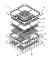
添付の図2は、従来(本発明者が既出願したもの)の四角単電池の四つの端部又は対向する二つの端部が∩字型に下向き折曲している単電池(図2a)と、これを用いて製作した内部マニフォールド形式のスタック構成(図2b)を示す図である。 The attached FIG. 2 shows a conventional single cell (filed by the inventor) whose four ends or two opposite ends are bent downward in a ∩ shape (FIG. 2 a). FIG. 2 is a diagram showing a stack configuration (FIG. 2B) of an internal manifold type manufactured using the same.
図2の単電池とスタックの構成のように、分離版8上にガスチャンネル6が形成されておる溝の間にチャンネル台7を載置し、単電池4を結合させ、封止材の溝12を通じて、単電池4と分離板8の封止部分を単純化し、熱応力の解消のために多孔性絶縁板10、つまり、セラミックス絶縁フェルト(felt)と封止ガラス(sealing glass)で封止(sealing)し、このような順番で積層し続けて、最終的に要される電圧(電力量)によって垂直に単電池及び構成要素などを積層して燃料電池スタックを製作した。
As in the configuration of the unit cell and the stack in FIG. 2, the channel table 7 is placed between the grooves in which the
従って、従来例である図1のように単純な平板型単電池を用いた場合より、他の従来例である図2では、必ずガス封止が要される部分を分離した形態で、余裕空間(封止溝)を有し、封止材を挿入することができるため、より改善された形態の封止条件を得ることができる。従って、封止機能が向上でき、全体スタックを再昇温及び冷却しながら熱サイクルとして使用することができ、温度変化への耐久性も優れたスタックを製造することができる。 Therefore, compared to the case of using a simple flat plate type cell as in FIG. 1 as a conventional example, in FIG. 2 as another conventional example, a portion in which gas sealing is required is always separated, and a marginal space is provided. (Sealing groove), and a sealing material can be inserted, so that a more improved form of sealing conditions can be obtained. Therefore, the sealing function can be improved, the entire stack can be used as a thermal cycle while the temperature is raised and cooled again, and a stack excellent in durability against temperature changes can be manufactured.
しかし、図2aの単電池を用いて、図2bのようなスタックを製作する場合、チャンネル台7と分離板8のチャンネル構造が付加的に載置されなければならない。このような分離板におけるチャンネル構造は、分離板の製造費用を上昇させ、SOFCスタックの製作コストを上昇させる短所がある。従って、図2bの単電池4が、製作・成型時からチャンネル構造を有するようにすれば、スタック製作において、燃料極又は空気極のチャンネル構造を有しない単純な板上の分離板をそのまま使用することができ、これによって、SOFCスタックの製作時、相対的に安い分離板を用いることができる。
However, when a stack as shown in FIG. 2B is manufactured using the unit cell of FIG. 2A, the channel structure of the channel base 7 and the
本発明の目的は、単電池の内部及び/又は外部にガスチャンネルを有する固体酸化物燃料電池を提供することにある。 An object of the present invention is to provide a solid oxide fuel cell having gas channels inside and / or outside a cell.
さらに本発明の他の目的は、SOFCスタックの製作時、分離板に燃料極又は空気極のチャンネルを製作する必要がなくて、経済的に安価な分離板を利用できる固体酸化物燃料電池を提供することにある。 Still another object of the present invention is to provide a solid oxide fuel cell which can use an economically inexpensive separator without the need to manufacture a fuel electrode or air electrode channel in the separator when fabricating an SOFC stack. Is to do.
さらに本発明の他の目的は、SOFCスタックの製作時、分離板に燃料極又は空気極のチャンネルを製作する必要がなくて、分離板の厚さを減少できる固体酸化物燃料電池を提供することにある。 It is still another object of the present invention to provide a solid oxide fuel cell that can reduce the thickness of a separator without the need to manufacture a fuel electrode or a cathode channel in the separator when fabricating an SOFC stack. It is in.
さらに本発明の他の目的は、SOFCスタックの製作時、従来と同じスタックの大きさで、より高い出力のスタックを製作できる固体酸化物燃料電池を提供することにある。 It is still another object of the present invention to provide a solid oxide fuel cell capable of manufacturing a higher output stack with the same stack size as the conventional one when manufacturing an SOFC stack.
さらに発明の他の目的は、単電池の長期性能に該当するチャンネルを有する部分である燃料極又は空気極において、高温クリップ抵抗を向上させて単電池の寿命を向上できる固体酸化物燃料電池を提供することにある。 Still another object of the present invention is to provide a solid oxide fuel cell capable of improving the high-temperature clip resistance at the fuel electrode or the air electrode, which is a portion having a channel corresponding to the long-term performance of the cell, and thereby improving the life of the cell. Is to do.
本発明の固体酸化物燃料電池の単電池は、燃料極(陰極)、電解質、空気極(陽極)で構成され、四つの端部又は対向する二つの端部の断面が∩字型に下向き折曲しており、かつ前記単電池の内部及び/又は外部にガスチャンネルを有することを特徴とする。 The unit cell of the solid oxide fuel cell of the present invention is composed of a fuel electrode (cathode), an electrolyte, and an air electrode (anode), and the four ends or two opposing ends are folded downward in a ∩ shape. It is curved and has a gas channel inside and / or outside the cell.
本発明の単電池は、四つの端部又は対向する二つの端部の断面が∩字型に下向き折曲している多孔性の燃料極(陰極)又は空気極(陽極)支持体に、厚さ5乃至50 mmの緻密な薄膜として電解質が被覆されておる電極支持体型の構造又は固体酸化物の電解質で厚さ50乃至2000 mmの∩字型に下向き折曲している構造を有しているし、その各々の上部又は下部に多孔性の空気極(陽極)又は燃料極(陰極)が被覆されている3重膜又はそれ以上の多重膜で構成されており、その内部および/又は外部にガスチャンネルを有していることを特徴としている。 The unit cell of the present invention is provided with a porous fuel electrode (cathode) or air electrode (anode) support having four ends or two opposite ends that are bent downward in a ∩ shape. It has a structure of an electrode support type in which an electrolyte is coated as a dense thin film having a thickness of 5 to 50 mm or a structure in which a solid oxide electrolyte is bent downward into a rectangular shape having a thickness of 50 to 2000 mm. It is composed of a triple membrane or more multiple membranes, each of which is coated with a porous air electrode (anode) or fuel electrode (cathode) on the upper or lower part, and its inner and / or outer It is characterized by having a gas channel.
本発明に係る単電池を用いる場合、分離板でのチャンネル加工時、上下両面の一方乃至は両方を除去することができ、従来の四つの端部又は対向する二つの端部の断面が∩字型に下向き折曲している単電池において、スタックで積層する際に使われるチャンネル台と分離板でのチャンネル加工を排除することができるため、比較的に低いコストで分離板を製作することができ、又、分離板の厚さも減少させることができるという長所がある。 When the unit cell according to the present invention is used, one or both of the upper and lower surfaces can be removed at the time of channel processing with the separator, and the cross section of the conventional four ends or the two opposite ends is a letter. In a unit cell that is bent downward in a mold, the channel plate used for stacking in a stack and the channel processing in the separator can be eliminated, so that the separator can be manufactured at a relatively low cost. And the thickness of the separator can be reduced.
本発明の燃料電池は、スタック積層の際、分離板上のチャンネル構造を単純化して分離板の厚さ及び費用を低減する長所がある。従って、相対的に同じ大きさのスタックに、より多くの単電池を積層することができるため、より大きい出力を得ることができる。これは特に、四つの端部又は対向する二つの端部の断面が∩字型に下向き折曲している単電池の製造時、支持体(例えば、空気極、電解質、燃料極)に対応する部分にチャンネルが含まれるように成型(プレス成型)することによって、燃料及び空気反応ガスが流れるチャンネルを別途に分離板に加工しなくて済む。 The fuel cell of the present invention has the advantage of simplifying the channel structure on the separator when stacking the stack, thereby reducing the thickness and cost of the separator. Therefore, a larger output can be obtained because more unit cells can be stacked in a stack having a relatively same size. This corresponds to a support (eg, air electrode, electrolyte, fuel electrode) particularly when manufacturing a cell in which the cross section of four ends or two opposite ends is bent downward in a ∩ shape. By molding (press molding) such that the channel is included in the portion, it is not necessary to separately process the channel through which the fuel and the air reaction gas flow into a separation plate.
このような技術は従来のSOFC開発において障害となっていた高費用の分離板製作という短所を補完でき、安価なSOFCスタックを製造できる効果がある。 Such a technique can compensate for the disadvantage of manufacturing a high-cost separator, which has been an obstacle in the conventional SOFC development, and has the effect of manufacturing an inexpensive SOFC stack.
又、本発明は、全体的に単電池の形態を改善して、SOFCスタックの価格を安くすることができ、又、より多くの分離板を使用することによって、スタックの大きさを小型化することによって、究極的には寿命と耐久性、運転条件の容易性を向上させる効果がある。ここで開示した実施例は、様々な実施可能な例の中で、当業者の理解を助けるように、もっとも好適な例を選んで提示したものに過ぎず、本発明の技術思想はこの実施例に限られるものではなく、本発明の技術的思想から外れていいない範囲内で、多様に変化と変更が可能であり、均等な他の実施例も可能である。 In addition, the present invention can improve the shape of the cell as a whole, reduce the price of the SOFC stack, and reduce the size of the stack by using more separators. This ultimately has the effect of improving the life, durability, and ease of operating conditions. The embodiment disclosed herein is merely a selection and presentation of the most suitable example among various possible examples to assist those skilled in the art, and the technical idea of the present invention is not limited to this embodiment. The present invention is not limited to this, and various changes and modifications are possible without departing from the technical idea of the present invention, and other equivalent embodiments are also possible.
以下、本発明に係る実施例について、添付図面を参照して詳細に説明する。
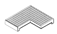
本発明において、図3は、本発明に係る四角単電池の四つの端部又は対向する二つの端部の断面が∩字型に下向き折曲している単電池の支持体に、反応ガスチャンネルが形成されている単電池の模式図を示すものである。この中で、図3aは、四つの端部の断面が∩字型に下向き折曲している燃料極(陰極)支持体型単電池で、燃料極(陰極)支持体における反応ガスチャンネルが碁盤状の構造で形成されている。図3bは、四つの端部の断面が下向き折曲している燃料極(陰極)支持体型単電池で、燃料極(陰極)支持体における反応ガスチャンネルが直線形状の構造で形成されている。又、3cは、対向する二つの端部の断面が∩字型に下向き折曲している燃料極(陰極)支持体型単電池で、燃料極支持体における反応ガスチャンネルが直線形状の構造で形成されている。図3dは対向する二つの端部の断面が∩字型に下向き折曲している燃料極(陰極)支持体型単電池で、燃料極(陰極)支持体における反応ガスチャンネルが碁盤状の構造で形成されている。
Hereinafter, embodiments according to the present invention will be described in detail with reference to the accompanying drawings.
In the present invention, FIG. 3 shows a reaction gas channel formed on a support of a unit cell in which four ends or two opposite ends of the square unit cell according to the present invention are bent downward in a ∩ shape. 1 is a schematic view of a unit cell in which is formed. FIG. 3a shows a fuel cell (cathode) support type cell in which four end sections are bent downward in a ∩-shape, and the reaction gas channels in the fuel electrode (cathode) support are in a grid pattern. It is formed with the structure of. FIG. 3b is a fuel cell (cathode) support type single cell in which four end sections are bent downward, and the reaction gas channel in the fuel electrode (cathode) support is formed in a linear structure. Reference numeral 3c denotes a fuel cell (cathode) support type single cell in which the cross section of two opposing ends is bent downward in a ∩ shape, and the reaction gas channel in the fuel electrode support is formed in a linear structure. Have been. FIG. 3d shows a fuel cell (cathode) support type cell in which the cross sections of two opposing ends are bent downward in a ∩ shape, and the reaction gas channels in the fuel electrode (cathode) support have a checkerboard structure. Is formed.
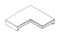
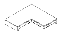
図4は、図3の各単電池において、折曲部の2次元断面を示す模式図であり、図4aは、支持体の折曲部全体を電解質で囲んでおり、図4bは、支持体の折曲部の一部を電解質で囲んでいる場合の模式図である。 FIG. 4 is a schematic diagram showing a two-dimensional cross section of a bent portion in each of the unit cells of FIG. 3, FIG. 4a shows the entire bent portion of the support surrounded by an electrolyte, and FIG. FIG. 4 is a schematic diagram when a part of a bent portion of the above is surrounded by an electrolyte.
図5は、本発明に係る四角単電池の四つの端部又は対向する二つの端部の断面が∩字型に下向き折曲している単電池の空気極支持体に、反応ガスチャンネルが形成されている単電池の模式図として、図5aは、四つの端部の断面が∩字型に下向き折曲している空気極(陽極)支持体型単電池で、直線形状の構造で反応ガスチャンネルが形成されている単電池であり、図5bは、四つの端部の断面が下向き折曲している空気極(陽極)支持体型単電池で、碁盤状の構造で反応ガスチャンネルが形成されている単電池であり、図5cは、対向する二つの端部の断面が∩字型に下向き折曲している空気極(陽極)支持体型単電池で、直線形状の構造で反応ガスチャンネルが形成されている単電池であり、図5dは、対向する二つの端部の断面が∩字型に下向き折曲している空気極(陽極)支持体型単電池で、碁盤状の構造で反応ガスチャンネルが形成されている単電池である。 FIG. 5 shows that the reaction gas channel is formed in the air electrode support of the unit cell in which the cross section of the four ends or the two opposite ends of the square unit cell according to the present invention is bent downward in a ∩ shape. FIG. 5A is a schematic view of a unit cell that has been formed. FIG. 5A shows an air electrode (anode) support unit cell whose four end sections are bent downward in a ∩ shape, and has a linear structure and a reaction gas channel. FIG. 5b shows an air electrode (anode) support type cell having four end sections bent downward, in which a reactive gas channel is formed in a grid-like structure. FIG. 5c shows an air electrode (anode) support type cell in which two opposing ends are bent downward in a ∩ shape, and a reaction gas channel is formed in a linear structure. FIG. 5d shows a cross section of two opposing ends of a cell. The air electrode (anode)-supported unit cell are downwardly bent, a single cell reactant gas channel is formed in a checkerboard-like structure.
図6は、本発明に係る四角単電池の四つの端部又は対向する二つの端部の断面が∩字型に下向き折曲している単電池の電解質に反応ガスチャンネルが存在する単電池の模式図として、図6aは、四つの端部の断面が∩字型に下向き折曲している電解質支持体型単電池で、電解質支持体に反応ガスチャンネルが直線形状の構造で形成されている単電池であり、図6bは、四つの端部の断面が∩字型に下向き折曲している電解質支持体型単電池で、電解質支持体に反応ガスチャンネルが碁盤状の構造で形成されている単電池であり、図6cは、対向する二つの端部の断面が∩字型に下向き折曲している電解質支持体型単電池で、電解質支持体に反応ガスチャンネルが直線形状の構造で形成されている単電池であり、図6dは、対向する二つの端部の断面が∩字型に下向き折曲している電解質支持体型単電池で、電解質支持体に反応ガスチャンネルが碁盤状の構造で形成されている単電池である。 FIG. 6 is a cross-sectional view of a rectangular cell according to the present invention, in which a reaction gas channel exists in the electrolyte of a cell whose four ends or two opposing ends are bent downward in a ∩ shape in cross section. As a schematic diagram, FIG. 6A shows an electrolyte-supported unit cell in which four end sections are bent downward in a ∩ shape, in which a reaction gas channel is formed in the electrolyte support in a linear structure. FIG. 6b shows an electrolyte-supported unit cell in which four end sections are bent downward in a ∩-shape, and a reaction gas channel is formed in the electrolyte support in a grid-like structure. FIG. 6c shows an electrolyte-supported unit cell in which the cross sections of two opposite ends are bent downward in a 、 -shape, in which a reaction gas channel is formed in a linear structure in the electrolyte support. Fig. 6d shows two opposite ends. An electrolyte-supported unit cell section is downwardly bent ∩-shape, a single-cell reaction gas channel in an electrolyte support are formed in a checkerboard-like structure.
このような本発明を実施例により、より詳しく説明すると、次の通りである。 The present invention will be described in more detail with reference to the following examples.
実施例1;四つの端部又は対向する二つの端部の断面が∩字型に下向き折曲しており、反応ガスチャンネルを有する燃料極(陰極)支持体型単電池Example 1 A fuel cell (cathode) support type cell having a cross section of four ends or two opposite ends bent downward in a ∩ shape and having a reaction gas channel
本発明で使用したチャンネル構造の折曲型単電池とは、図2aに示すように、平板部31の四つの端部又は対向する二つの端部の断面が∩字型に下向き折曲しており、かつ、相対的に厚い燃料極支持体に、燃料ガスの流れを容易にするチャンネルを有する単電池のことである。
As shown in FIG. 2A, the bent type cell having the channel structure used in the present invention is such that the cross section of the four ends or two opposite ends of the
この単電池は、折曲部32と支持部33で構成されており、厚さ約1乃至2mmの多孔性の燃料極(陰極)1と、厚さ5乃至50 mmの緻密な薄膜で支持部33上面と端部全体に電解質2が被覆されており、電解質2が被覆された部分の上部に多孔性の空気極(陽極)3が被覆されているもので、中心部は電解質2、下部は燃料極(陰極)1、上部は空気極(陽極)3で構成されている3重膜の単電池である。
This unit cell is composed of a bent portion 32 and a
この際、最終的に、単電池は、図3a、図3b、図3c及び図3dのような形態に製造することができ、例えば、大きさは約50×50mmであり、厚さは約1.7mmであり、下向き折曲している端部の高さは約3.5mm、内側の高さは1.8mm、折曲部の広さ方向の厚さは約2mmである。 At this time, finally, the unit cell can be manufactured in a shape as shown in FIGS. 3A, 3B, 3C, and 3D. For example, the size is about 50 × 50 mm, and the thickness is about 1 × 10 mm. The height of the downwardly bent end is about 3.5 mm, the height of the inside is 1.8 mm, and the thickness of the bent part in the width direction is about 2 mm.
これらの製造方法は、1次焼結体である燃料極支持体に、公知のスラリーコーティング法と化学気象蒸着法を用いて、ジルコニア(ZrO2)系、セリアー(CeO2)系、ビスムス酸化物(Bi2O3)系、ランタン系ペロブスカイト(perovskite)系のうち、1つ又はそれ以上の電解質をコーティングし、約1250℃で熱処理を1回乃至数回繰り返した後、最終的には1450℃乃至1600℃で焼結して約5乃至50mm厚さの緻密な電解質層を製造する方法である。 These manufacturing methods use a known slurry coating method and a chemical meteorological vapor deposition method to coat a fuel electrode support, which is a primary sintered body, with a zirconia (ZrO 2 ) -based, ceria (CeO 2 ) -based, bismuth oxide One or more electrolytes of (Bi 2 O 3 ) type and lanthanum type perovskite type are coated, and heat treatment is repeated once or several times at about 1250 ° C. and finally at 1450 ° C. This is a method of manufacturing a dense electrolyte layer having a thickness of about 5 to 50 mm by sintering at about 1600 ° C.
ここで、図4aのように、折曲部全体を緻密な電解質層で囲むこともでき、図4bに示すように、緻密な電解質層を燃料極支持体の上部表面と支持体折曲部の側面にコーティングすることもでき、これによってSOFC作動時、多孔性の支持体から直接的に燃料ガスが漏れることを防止でき、封止効果も増大することができる。 Here, as shown in FIG. 4A, the entire bent portion can be surrounded by a dense electrolyte layer. As shown in FIG. 4B, the dense electrolyte layer is formed by the upper surface of the anode support and the bent portion of the support body. Side coatings can also be provided, which can prevent fuel gas from leaking directly from the porous support during SOFC operation and increase the sealing effect.
そして、それぞれの折曲部とチャンネル構造、例えば直線形状の構造又は碁盤状の構造は様々な形態に変形することができる。すなわち、直線形状の構造において、単純な直角構造でなく鈍角又は鋭角の組合せである梯形にすることもでき、碁盤状の構造において、突出部の形態を四角形、多角形及び/又は円形などのように様々な形態に製作することもできる。 And each bent part and channel structure, for example, a linear structure or a checkerboard structure, can be transformed into various forms. That is, in a straight-line structure, a trapezoid that is a combination of obtuse angles or acute angles can be used instead of a simple right-angled structure. In a checkerboard-like structure, the shape of a protruding portion is a square, a polygon, and / or a circle. It can also be manufactured in various forms.
そして、電解質層の上面は20%の黒鉛粉末を含むLSM(La0.85Sr0.15MnO3)+YSZ組成粉末のペイストを用いて、空気極(陽極)をスクリーン印刷し、乾燥した後、1,100℃で熱処理して、最終的に図3a又は図4bのような3層構造の燃料極(陰極)支持体型構造のSOFC単電池を製造した。 The upper surface of the electrolyte layer is screen-printed with an air electrode (anode) using a paste of LSM (La 0.85 Sr 0.15 MnO 3 ) + YSZ composition powder containing 20% of graphite powder, and dried, Heat treatment was performed at 1,100 ° C. to finally produce an SOFC cell having a three-layer fuel electrode (cathode) support type structure as shown in FIG. 3A or 4B.
スタックの製作・組立のためには、それぞれの単電池が同じ大きさを有するように製作することが重要であり、折曲部の大きさ及び高さは、それぞれの単電池を分離板と接触し、封止する方法によって再加工することができる。特に、格子配列方式で単電池を付着してスタックの一層を構成しようとする際(図1(b))には、それぞれの単電池の厚さ及び折曲部の高さを、同じ大きさに製作しなければならない。 In order to manufacture and assemble the stack, it is important to manufacture each cell so that each cell has the same size, and the size and height of the bent portion make each cell contact the separator. Then, it can be reprocessed by a sealing method. In particular, when unit cells are to be attached in a lattice arrangement system to form a single layer of a stack (FIG. 1B), the thickness of each unit cell and the height of the bent portion are set to the same size. Must be manufactured.
本実施例では最終単電池の大きさを約50×50mmにする場合、折曲している端部の高さは約3.5mm、内側の高さは1.8mm、単電池の内側のガスチャンネルの谷部(凹部)の深さは約1mm内外にし、このような条件は単電池の製作時、プレス金型の大きさと熱処理又は焼結温度により決められる。 In this embodiment, when the size of the final cell is about 50 × 50 mm, the height of the bent end is about 3.5 mm, the inside height is 1.8 mm, and the gas inside the cell is gas. The depth of the valleys (recesses) of the channel is about 1 mm inside and outside, and such conditions are determined by the size of the press die and the heat treatment or sintering temperature when the unit cell is manufactured.
本発明に係る単電池では、内側チャンネルのガス分布を一定に維持し、電気的接触を行うために、集電層と集電体を使う。そして多孔性金属シート状(フェルト、felt)とマッシュ(mesh)を用いているため、分離板との接触に容易である。 In the unit cell according to the present invention, a current collecting layer and a current collector are used to maintain a constant gas distribution in the inner channel and make electrical contact. Since the porous metal sheet (felt) and the mash are used, it is easy to make contact with the separation plate.
実施例2:四つの端部又は対向する二つの端部の断面が∩字型に下向き折曲しており、反応ガスチャンネルを有する空気極(陽極)支持体型単電池Example 2: Air electrode (anode) support type cell having four end portions or two opposite end portions bent downward in a ∩ shape and having a reaction gas channel
まず、空気極(陽極)支持体を製造するために、LSM(La0.85Sr0.15MnO3)組成の粉末に、球形の黒鉛粉末を混合し、公知のプレス成型及び熱処理条件に基づいて、最終的に約40%の多孔性空気極(陽極)支持体を製造した。 First, in order to manufacture an air electrode (anode) support, spherical graphite powder is mixed with LSM (La 0.85 Sr 0.15 MnO 3 ) powder, and the mixture is subjected to known press molding and heat treatment conditions. Finally, about 40% of a porous cathode (anode) support was produced.
このような空気極(陽極)支持体は、図5a、図5b、図5c及び図5dのような形態に製造され、大きさは約50×50mm、厚さは約1.7mm、下向き折曲している端部の高さは約3.5mm、内側の高さは1.8mm、折曲部の広さ方向の厚さは約3mmとなるようにした。 Such an air electrode (anode) support is manufactured in a shape as shown in FIGS. 5a, 5b, 5c and 5d, and has a size of about 50 × 50 mm, a thickness of about 1.7 mm, and a downward bent. The height of the bent end was about 3.5 mm, the height of the inside was 1.8 mm, and the thickness of the bent part in the width direction was about 3 mm.
前記空気極(陽極)支持体の下面全体に緻密な電解質層を形成した後、再びその下面に燃料極(陰極)成分としてNiO粉末と8YSZ(ZrO2+8モール%Y2O3)を重量比約50:50で混合した粉末と、20%の黒鉛粉末を出発原料として、実施例と同じ印刷法を用いて、最終的に図5a、図5b、図5c及び図5dのような空気極(陽極)支持体型構造のSOFC単電池を製造した。 After a dense electrolyte layer is formed on the entire lower surface of the air electrode (anode) support, NiO powder and 8YSZ (ZrO 2 +8 mole% Y 2 O 3 ) are again used as a fuel electrode (cathode) component on the lower surface thereof by weight ratio. Using the powder mixed at about 50:50 and 20% graphite powder as starting materials, using the same printing method as in the example, finally the air electrode (FIG. 5a, FIG. 5b, FIG. 5c and FIG. Anode) An SOFC cell having a support type structure was manufactured.
特に、図5a、図5b、図5c及び図5dのように反応ガスチャンネルを直線形状の構造又は碁盤状の構造にし、この際のチャンネル構造は直線形状の構造において、単純な直角形状の構造でない鈍角と鋭角の組合せである梯形であることも可能であり、碁盤状の構造において、突出部の形態は四角形、多角形及び/又は円形などのように様々な形態に製作することもできる。これらは成型の際、プレス金型の形態によって決められる。以下の内容は実施例1と同様である。 In particular, as shown in FIGS. 5a, 5b, 5c and 5d, the reaction gas channel has a linear structure or a checkerboard structure. In this case, the channel structure is not a simple right-angled structure but a linear structure. The trapezoid may be a combination of an obtuse angle and an acute angle, and the shape of the protrusion may be formed in various shapes such as a quadrangle, a polygon, and / or a circle. These are determined by the form of the press mold during molding. The following contents are the same as in the first embodiment.
実施例3:四つの端部又は対向する二つの端部の断面が∩字型に下向き折曲しており、反応ガスチャンネルを有する電解質支持体型単電池Example 3: Electrolyte-supported unit cell having four ends or two opposite ends bent downward in a ∩ shape and having a reaction gas channel
電解質支持体型又は自立型単電池を製造するにおいて、ジルコニア(ZrO2)系、セリアー(CeO2)系、ビスムス酸化物(Bi2O3)系、ペロブスカイト(perovskite)系のうち、1つ又はその以上の固体酸化物電解質原料粉末を10乃至100mmの大きさに粗粒化した後、これを用いて図6a、図6b、図6c及び図6dのような形態になるように成型した後、焼結して最終的に大きさが約50×50mm、厚さは約1mm以下、下向き折曲している端部の内側高さが約2mm、端部の厚さが約1乃至2mmである電解質板を製作した。 In manufacturing an electrolyte support type or a self-supporting unit cell, one or more of zirconia (ZrO 2 ), ceria (CeO 2 ), bismuth oxide (Bi 2 O 3 ), and perovskite (perovskite) are used. After the above solid oxide electrolyte raw material powder is coarsened to a size of 10 to 100 mm, it is molded into a shape as shown in FIGS. 6a, 6b, 6c and 6d, and then sintered. Finally, the electrolyte has a size of about 50 × 50 mm, a thickness of about 1 mm or less, an inner height of the downward bent end of about 2 mm, and a thickness of the end of about 1 to 2 mm. A board was made.
この際、内側には原料粉末の成型時、プレス金型の形態によって谷部(凹部)の幅と深さを約1〜0.5mmにそれぞれ成型し、図6a及び図6cのように直線形状の構造のチャンネルを有するか、図6b及び図6dのように碁盤状の構造のチャンネルを有する構造に製作することができる。上述したように、このようなチャンネル構造は直線形状の構造において、単純な直角形状の構造でない鈍角と鋭角の組合せである梯形であることも可能であり、碁盤状の構造において、突出部の形態は四角形、多角形及び/又は円形など、様々な形態に製作することもできる。 At this time, the width and depth of the valleys (concave portions) are formed to about 1 to 0.5 mm depending on the shape of the press mold when molding the raw material powder on the inner side, and are linearly shaped as shown in FIGS. 6b or 6d, as shown in FIGS. 6b and 6d. As described above, such a channel structure may have a trapezoidal shape that is a combination of an obtuse angle and an acute angle instead of a simple right-angled structure in a straight-line structure. Can be manufactured in various forms, such as square, polygonal and / or circular.
ここで、通常の方法によって製造された燃料極の成分であるNiO粉末と8YSZ(ZrO2+8モール%Y2O3)を重量比約50:50で混合した粉末と、20%の黒鉛粉末を出発原料として燃料極ペイストを製造した。これを製造された電解質板の下面、特に、反応ガスチャンネルの山部(凸部)又は谷部(凹部)にそれぞれ印刷乃至塗布して乾燥した後、1300乃至1450℃の温度で熱処理して燃料極を形成した。実施例1と同様に、再び空気極の材料であるLSM(La0.8Sr0.2MnO3)+YSZペイストを印刷して乾燥した後、1100℃内外で熱処理して、言わばチャンネル構造を有する電解質支持体型又は自立型構造のSOFC単電池を製造した。以下、実施例1及び2と同様である。 Here, a powder obtained by mixing NiO powder, which is a component of the fuel electrode, and 8YSZ (ZrO 2 +8 mol% Y 2 O 3 ) at a weight ratio of about 50:50, and a 20% graphite powder, An anode paste was manufactured as a starting material. This is printed or coated on the lower surface of the manufactured electrolyte plate, particularly on the peaks (convex portions) or the valleys (concave portions) of the reaction gas channels, and then dried, and then heat-treated at a temperature of 1300 to 1450 ° C. The pole was formed. As in Example 1, LSM (La 0.8 Sr 0.2 MnO 3 ) + YSZ paste, which is a material of the air electrode, is printed and dried, and then heat-treated at 1100 ° C. to have a channel structure. An SOFC cell having an electrolyte support type or a self-standing structure was manufactured. Hereinafter, it is similar to the first and second embodiments.
以下の本発明は、本発明の属する技術分野における通常の知識を有する者が容易に実施できるように詳細に説明したもので、本発明の最も好適な実施例を、添付の図面を参照して、詳細に説明することにする。本発明の目的、作用・効果を含めて、その他の目的、特徴は、好適な実施例の説明により、より明確になるだろう。 The present invention described below has been described in detail so that those skilled in the art to which the present invention pertains can be easily implemented, and the most preferred embodiments of the present invention will be described with reference to the accompanying drawings. , Will be described in detail. Other objects and features, including the objects, operations and effects of the present invention, will become more apparent from the description of the preferred embodiments.
1:燃料極(陰極)
2:電解質
3:空気極(陽極)
4:単電池
6:ガスチャンネル
7:チャンネル台
8:分離板
10:多孔性絶縁板
12:封止材の溝
31:平板部
32:折曲部
33:支持部
1: Fuel electrode (cathode)
2: Electrolyte 3: Air electrode (anode)
4: cell
6: Gas channel
7: Channel stand
8: separation plate
10: Porous insulating plate
12: Groove of sealing material
31: flat part
32: Bend
33: support
Claims (12)
One or more solid oxide electrolyte raw materials of at least one of zirconia (ZrO 2 ), ceria (CeO 2 ), bismuth oxide (Bi 2 O 3 ), and lanthanum perovskite are used. Using an assembling powder having a thickness of 100 mm, an electrolyte plate having a thickness of 50 to 2000 mm having four ends or a cross section of two ends bent downward in a ∩-shape is manufactured. 11. An electrolyte support type comprising a triple membrane or a multi-layer as a unit cell having a fuel electrode covered with an air electrode on the upper part of the electrolyte. Solid oxide fuel cell.
Applications Claiming Priority (1)
| Application Number | Priority Date | Filing Date | Title |
|---|---|---|---|
| KR20020065923 | 2002-10-28 |
Related Child Applications (1)
| Application Number | Title | Priority Date | Filing Date |
|---|---|---|---|
| JP2007276751A Division JP2008047545A (en) | 2002-10-28 | 2007-10-24 | Solid oxide fuel cell having gas channel |
Publications (1)
| Publication Number | Publication Date |
|---|---|
| JP2004152762A true JP2004152762A (en) | 2004-05-27 |
Family
ID=32089767
Family Applications (2)
| Application Number | Title | Priority Date | Filing Date |
|---|---|---|---|
| JP2003364800A Pending JP2004152762A (en) | 2002-10-28 | 2003-10-24 | Solid oxide fuel cell having gas channel |
| JP2007276751A Pending JP2008047545A (en) | 2002-10-28 | 2007-10-24 | Solid oxide fuel cell having gas channel |
Family Applications After (1)
| Application Number | Title | Priority Date | Filing Date |
|---|---|---|---|
| JP2007276751A Pending JP2008047545A (en) | 2002-10-28 | 2007-10-24 | Solid oxide fuel cell having gas channel |
Country Status (5)
| Country | Link |
|---|---|
| US (1) | US7255952B2 (en) |
| EP (1) | EP1416557A3 (en) |
| JP (2) | JP2004152762A (en) |
| KR (1) | KR100532203B1 (en) |
| CN (1) | CN1276537C (en) |
Cited By (3)
| Publication number | Priority date | Publication date | Assignee | Title |
|---|---|---|---|---|
| JP2006253071A (en) * | 2005-03-14 | 2006-09-21 | Central Res Inst Of Electric Power Ind | Structure of fuel electrode supporting type solid oxide fuel cell |
| JP2013543645A (en) * | 2010-10-19 | 2013-12-05 | ミム セラミックス カンパニー リミテッド | Solid oxide fuel cell |
| JP2018511140A (en) * | 2015-08-27 | 2018-04-19 | エルジー・ケム・リミテッド | Flat plate type solid oxide fuel cell and battery module including the same |
Families Citing this family (9)
| Publication number | Priority date | Publication date | Assignee | Title |
|---|---|---|---|---|
| KR100665391B1 (en) | 2004-10-30 | 2007-01-04 | 한국전력공사 | Advanced Planar Type of Solid Oxide Fuel Cells |
| US20070134540A1 (en) * | 2005-12-12 | 2007-06-14 | General Electric Company | Solid oxide electrochemical devices having a dimensionally stable bonding agent to bond an anode to anode interconnect and methods |
| KR101154217B1 (en) * | 2006-01-09 | 2012-06-18 | 생-고뱅 세라믹스 앤드 플라스틱스, 인코포레이티드 | Fuel cell components having porous electrodes |
| JP5350218B2 (en) * | 2006-04-05 | 2013-11-27 | サン−ゴバン セラミックス アンド プラスティクス,インコーポレイティド | SOFC laminate with high temperature bonded semi-rack interconnect and method of manufacturing the same |
| KR100835175B1 (en) * | 2006-12-07 | 2008-06-05 | 한국전자통신연구원 | System and method for digital communication using frequency selective baseband |
| KR100942091B1 (en) * | 2007-11-22 | 2010-02-12 | 주식회사 포스코 | Stacking structure of planar solid oxide fuel cell |
| KR101432386B1 (en) | 2012-12-18 | 2014-08-20 | 포스코에너지 주식회사 | Solid oxide fuel cell having longitudinal channel and transversal channel |
| CN105742674B (en) * | 2014-12-08 | 2018-07-24 | 中国科学院大连化学物理研究所 | A kind of cathode material of high-temperature fuel cell and preparation method thereof |
| CN105470529B (en) * | 2015-12-03 | 2018-12-14 | 苏州攀特电陶科技股份有限公司 | A kind of solid oxide fuel cell electrode and preparation method thereof and solid oxide fuel cell based on it |
Family Cites Families (4)
| Publication number | Priority date | Publication date | Assignee | Title |
|---|---|---|---|---|
| JPS6343265A (en) * | 1986-08-07 | 1988-02-24 | Mitsubishi Electric Corp | Manufacture of fuel cell |
| JP3151933B2 (en) * | 1992-05-28 | 2001-04-03 | 株式会社村田製作所 | Solid oxide fuel cell |
| JPH10321239A (en) * | 1997-05-19 | 1998-12-04 | Nippon Telegr & Teleph Corp <Ntt> | Electrode of fuel cell |
| KR100341402B1 (en) * | 1999-03-09 | 2002-06-21 | 이종훈 | Single Cell and Stack Structure of Solid Oxide Fuel Cell |
-
2003
- 2003-10-16 CN CNB2003101005381A patent/CN1276537C/en not_active Expired - Lifetime
- 2003-10-24 JP JP2003364800A patent/JP2004152762A/en active Pending
- 2003-10-27 US US10/694,695 patent/US7255952B2/en active Active
- 2003-10-28 EP EP03024575A patent/EP1416557A3/en not_active Withdrawn
- 2003-10-28 KR KR10-2003-0075524A patent/KR100532203B1/en active IP Right Grant
-
2007
- 2007-10-24 JP JP2007276751A patent/JP2008047545A/en active Pending
Cited By (3)
| Publication number | Priority date | Publication date | Assignee | Title |
|---|---|---|---|---|
| JP2006253071A (en) * | 2005-03-14 | 2006-09-21 | Central Res Inst Of Electric Power Ind | Structure of fuel electrode supporting type solid oxide fuel cell |
| JP2013543645A (en) * | 2010-10-19 | 2013-12-05 | ミム セラミックス カンパニー リミテッド | Solid oxide fuel cell |
| JP2018511140A (en) * | 2015-08-27 | 2018-04-19 | エルジー・ケム・リミテッド | Flat plate type solid oxide fuel cell and battery module including the same |
Also Published As
| Publication number | Publication date |
|---|---|
| US20040091766A1 (en) | 2004-05-13 |
| EP1416557A2 (en) | 2004-05-06 |
| KR20040038751A (en) | 2004-05-08 |
| JP2008047545A (en) | 2008-02-28 |
| CN1276537C (en) | 2006-09-20 |
| KR100532203B1 (en) | 2005-11-29 |
| CN1501536A (en) | 2004-06-02 |
| US7255952B2 (en) | 2007-08-14 |
| EP1416557A3 (en) | 2009-12-16 |
Similar Documents
| Publication | Publication Date | Title |
|---|---|---|
| JP2008047545A (en) | Solid oxide fuel cell having gas channel | |
| US6864009B2 (en) | Single cell and stack structure for solid oxide fuel cell stacks | |
| KR100538555B1 (en) | Anode-supported flat-tubular solid oxide fuel cell stack and fabrication method of it | |
| US7550217B2 (en) | Stack supported solid oxide fuel cell | |
| KR100889266B1 (en) | The combination structure of solid oxide fuel cell between electrode and interconnect | |
| US20080254335A1 (en) | Porous bi-tubular solid state electrochemical device | |
| US20140017597A1 (en) | Fuel cell | |
| JP4350403B2 (en) | Solid oxide fuel cell | |
| KR102030981B1 (en) | Metal-supported solid oxide fuel cell and manufacturing method | |
| US20120141906A1 (en) | Electrode material for fuel cell, fuel cell comprising the same and method of manufacturing the fuel cell | |
| KR100665391B1 (en) | Advanced Planar Type of Solid Oxide Fuel Cells | |
| JP2003331874A (en) | Interconnector for solid oxide fuel cell and its formation method | |
| US20140017598A1 (en) | Fuel cell | |
| KR101905499B1 (en) | Unit cell module and stack for solid oxide fuel cell | |
| US20140178799A1 (en) | Solid oxide fuel cell and manufacturing method thereof | |
| JP2980921B2 (en) | Flat solid electrolyte fuel cell | |
| JPH07145492A (en) | Steam electrolytic cell | |
| JP2948441B2 (en) | Flat solid electrolyte fuel cell | |
| JPH05151982A (en) | Solid electrolyte fuel cell | |
| JP2008277236A (en) | Solid oxide fuel cell, and its stack structure | |
| JPH0562694A (en) | Solid electrolyte type fuel cell | |
| KR101220598B1 (en) | Solid oxide fuel cell and method for manufacturing the same | |
| KR20230158438A (en) | Unit cell of fuel cell and fuel cell stack comprising same | |
| KR20140126035A (en) | Preliminary shaped body for unit cell and manufacturing method of solid oxide fuel cell | |
| KR101321249B1 (en) | Solid Oxide Fuel Cell and Method of manufacturing the same |
Legal Events
| Date | Code | Title | Description |
|---|---|---|---|
| A977 | Report on retrieval |
Free format text: JAPANESE INTERMEDIATE CODE: A971007 Effective date: 20041222 |
|
| A131 | Notification of reasons for refusal |
Free format text: JAPANESE INTERMEDIATE CODE: A131 Effective date: 20041228 |
|
| A601 | Written request for extension of time |
Free format text: JAPANESE INTERMEDIATE CODE: A601 Effective date: 20050328 |
|
| A602 | Written permission of extension of time |
Free format text: JAPANESE INTERMEDIATE CODE: A602 Effective date: 20050412 |
|
| A521 | Written amendment |
Free format text: JAPANESE INTERMEDIATE CODE: A523 Effective date: 20050628 |
|
| A02 | Decision of refusal |
Free format text: JAPANESE INTERMEDIATE CODE: A02 Effective date: 20050816 |
|
| A521 | Written amendment |
Free format text: JAPANESE INTERMEDIATE CODE: A523 Effective date: 20051130 |
|
| A521 | Written amendment |
Free format text: JAPANESE INTERMEDIATE CODE: A821 Effective date: 20051130 |
|
| A521 | Written amendment |
Free format text: JAPANESE INTERMEDIATE CODE: A821 Effective date: 20060216 |
|
| A601 | Written request for extension of time |
Free format text: JAPANESE INTERMEDIATE CODE: A601 Effective date: 20070723 |
|
| A602 | Written permission of extension of time |
Free format text: JAPANESE INTERMEDIATE CODE: A602 Effective date: 20070726 |
|
| A601 | Written request for extension of time |
Free format text: JAPANESE INTERMEDIATE CODE: A601 Effective date: 20070817 |
|
| A602 | Written permission of extension of time |
Free format text: JAPANESE INTERMEDIATE CODE: A602 Effective date: 20070822 |
|
| A601 | Written request for extension of time |
Free format text: JAPANESE INTERMEDIATE CODE: A601 Effective date: 20070921 |
|
| A602 | Written permission of extension of time |
Free format text: JAPANESE INTERMEDIATE CODE: A602 Effective date: 20071002 |
|
| A521 | Written amendment |
Free format text: JAPANESE INTERMEDIATE CODE: A523 Effective date: 20071024 |