JP2004152003A - Tab paper double-side printing method, tab paper double-side printing program, computer-readable storage medium storing the program and printing control device - Google Patents
Tab paper double-side printing method, tab paper double-side printing program, computer-readable storage medium storing the program and printing control device Download PDFInfo
- Publication number
- JP2004152003A JP2004152003A JP2002316400A JP2002316400A JP2004152003A JP 2004152003 A JP2004152003 A JP 2004152003A JP 2002316400 A JP2002316400 A JP 2002316400A JP 2002316400 A JP2002316400 A JP 2002316400A JP 2004152003 A JP2004152003 A JP 2004152003A
- Authority
- JP
- Japan
- Prior art keywords
- printing
- drawing data
- tab
- page
- Prior art date
- Legal status (The legal status is an assumption and is not a legal conclusion. Google has not performed a legal analysis and makes no representation as to the accuracy of the status listed.)
- Pending
Links
- 238000007639 printing Methods 0.000 title claims abstract description 139
- 238000000034 method Methods 0.000 title claims description 67
- 238000004441 surface measurement Methods 0.000 claims description 3
- 230000008569 process Effects 0.000 description 53
- 238000012545 processing Methods 0.000 description 42
- 230000015654 memory Effects 0.000 description 28
- 230000006870 function Effects 0.000 description 27
- 238000010586 diagram Methods 0.000 description 18
- 238000012546 transfer Methods 0.000 description 8
- 238000004364 calculation method Methods 0.000 description 6
- 101000674731 Homo sapiens TGF-beta-activated kinase 1 and MAP3K7-binding protein 1 Proteins 0.000 description 3
- 102100021228 TGF-beta-activated kinase 1 and MAP3K7-binding protein 1 Human genes 0.000 description 3
- 101000674728 Homo sapiens TGF-beta-activated kinase 1 and MAP3K7-binding protein 2 Proteins 0.000 description 2
- 101000674732 Homo sapiens TGF-beta-activated kinase 1 and MAP3K7-binding protein 3 Proteins 0.000 description 2
- 102100021227 TGF-beta-activated kinase 1 and MAP3K7-binding protein 2 Human genes 0.000 description 2
- 102100021229 TGF-beta-activated kinase 1 and MAP3K7-binding protein 3 Human genes 0.000 description 2
- 238000006243 chemical reaction Methods 0.000 description 2
- 238000004891 communication Methods 0.000 description 2
- 238000003672 processing method Methods 0.000 description 2
- 230000009467 reduction Effects 0.000 description 2
- 230000002457 bidirectional effect Effects 0.000 description 1
- 230000008859 change Effects 0.000 description 1
- 239000003086 colorant Substances 0.000 description 1
- 238000013500 data storage Methods 0.000 description 1
- 238000005034 decoration Methods 0.000 description 1
- 230000001419 dependent effect Effects 0.000 description 1
- 238000013461 design Methods 0.000 description 1
- 238000011161 development Methods 0.000 description 1
- 238000007599 discharging Methods 0.000 description 1
- 230000000694 effects Effects 0.000 description 1
- 238000005516 engineering process Methods 0.000 description 1
- 230000010365 information processing Effects 0.000 description 1
- 238000003780 insertion Methods 0.000 description 1
- 230000037431 insertion Effects 0.000 description 1
- 238000007726 management method Methods 0.000 description 1
- 239000000463 material Substances 0.000 description 1
- 230000007246 mechanism Effects 0.000 description 1
- 230000003287 optical effect Effects 0.000 description 1
- 238000004080 punching Methods 0.000 description 1
- 230000004044 response Effects 0.000 description 1
- 230000007306 turnover Effects 0.000 description 1
Images


Classifications
-
- B—PERFORMING OPERATIONS; TRANSPORTING
- B41—PRINTING; LINING MACHINES; TYPEWRITERS; STAMPS
- B41J—TYPEWRITERS; SELECTIVE PRINTING MECHANISMS, i.e. MECHANISMS PRINTING OTHERWISE THAN FROM A FORME; CORRECTION OF TYPOGRAPHICAL ERRORS
- B41J3/00—Typewriters or selective printing or marking mechanisms characterised by the purpose for which they are constructed
- B41J3/60—Typewriters or selective printing or marking mechanisms characterised by the purpose for which they are constructed for printing on both faces of the printing material
-
- B—PERFORMING OPERATIONS; TRANSPORTING
- B41—PRINTING; LINING MACHINES; TYPEWRITERS; STAMPS
- B41J—TYPEWRITERS; SELECTIVE PRINTING MECHANISMS, i.e. MECHANISMS PRINTING OTHERWISE THAN FROM A FORME; CORRECTION OF TYPOGRAPHICAL ERRORS
- B41J13/00—Devices or arrangements of selective printing mechanisms, e.g. ink-jet printers or thermal printers, specially adapted for supporting or handling copy material in short lengths, e.g. sheets
- B41J13/0063—Handling thick cut sheets, e.g. greeting cards or postcards, larger than credit cards, e.g. using means for enabling or facilitating the conveyance of thick sheets
Abstract
Description
【0001】
【発明の属する技術分野】
本発明は、印刷制御装置及びタブ紙両面印刷方法、プログラム及び記憶媒体に関するもので、特にパーソナルコンピュータ等の情報処理装置と、プリンタからなるシステムにおけるタブの生成、および印刷制御に関するものである。
【0002】
【従来の技術】
タブ紙とは、A4、もしくはレター用紙に、項目やタイトルを示す’タブ’がついたもので、タブが10個設けられた10タブ用紙やタブが5個設けられた5タブ用紙と呼ばれるものが、代表的なタブ紙である。タブの部分は、レターの場合で1/2インチが標準であるが、これ以外の大きさのタブを有するタブ用紙も存在する。普通の用紙に比べタブがついていること、また、タブ紙には通常厚紙が使用されており従来の印刷装置では搬送系で紙詰まりを起こすという問題から、タブ紙への印字をサポートしていないものがほとんどである。しかしながら、近年では紙の搬送系の技術向上により、印刷装置でのタブ紙印刷が行えるようになっている(下記の特許文献1参照)。また、これに伴い、マルチファンクション機と呼ばれるプリンタ機能等を備えた印刷装置では、コンピュータ上で作成したタブを、プリンタドライバを介して、印字を行うということも可能である。
【0003】
【特許文献1】
特開平10−67458号公報
【0004】
【発明が解決しようとする課題】
しかしながら、タブ紙の印刷を印刷装置で行えるようになったといっても、これは片面印刷の場合だけで、両面印刷は、印刷装置の搬送系の問題から、行えないのが通常である。これは、タブ紙が厚紙であるためで、両面印刷時に行う紙の裏返しが、技術的に非常に難しいからである。
【0005】
しかしながら、タブ紙のタブに印刷する項目やタイトルは、その中に含まれている原稿の内容を表すものなので、裏から見てわかること、つまり、裏面にも印刷されていることが、非常に重要である。
【0006】
厚紙の裏返しが出来ないという印刷装置の物理的な制限を克服するために、タブの片面だけが印刷されたタブ紙を、排紙トレイに出力されている印刷物から取り除き、これを裏返して給紙トレイや手差しトレイにセットして再度タブ紙の裏面だけの印刷を行うという方法をとることが考えられるが、その場合は、印刷装置の機構上、用紙搬送方向に対するタブの向きを一定にする必要がある。
【0007】
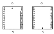
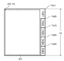
図4は、用紙搬送方向と、タブ原稿向きの関係を示す図である。図中の矢印は搬送方向を示し、図中の丸点は、原稿向きの上側を示している。
【0008】
図4(a)は、表面に対するタブ紙の用紙の状態と、印刷されるデータの一例であり、図4(b)は、裏面に対するタブ紙の用紙の状態と、印刷されるデータの一例である。
【0009】
図4(a)に示すように、タブが原稿向きに対して上から並ぶように用紙をセットした場合、タブ原稿は「TAB1」、「TAB2」、「TAB3」、「TAB4」、「TAB5」の順で5ページ用意することになる。
【0010】
一方、図4(b)に示すように、タブ紙裏面の印刷に対して、タブが原稿向きに対して上から並ぶように用紙をセットした場合、タブ原稿は表面とは逆、すなわち、「TAB5」、「TAB4」、「TAB3」、「TAB2」、「TAB1」の順で5ページ用意することになる。こうした方法は非常に不便な上、ユーザーが用紙のセット順を間違え易いという問題が生じてしまう。
【0011】
また、ユーザーは表面と裏面に印刷されるタブ情報を合わせるために、表面用のタブレイアウトと、裏面用のタブレイアウトの2種類の原稿を用意しなければならないという問題もある。
【0012】
【課題を解決するための手段】
本発明は、このような問題を解決し、1種類のタブ紙用原稿を用意するだけで、現在の印刷装置では対応していないタブ紙の両面印刷を行うことを可能とするものである。
【0013】
具体的には、本発明はタブ紙両面印刷方法であって、タブ紙印刷の設定がされているかを判定するための印刷設定判定工程と、前記タブ紙印刷の設定がされていると判定された場合に、印刷しようとする面が表面か裏面かを判定するための印刷面判定工程と、前記印刷しようとする面が前記表面であると判定された場合には第1の描画データを生成し、前記裏面であると判定された場合には前記第1の描画データを調整することにより第2の描画データを生成する描画データ生成工程とを備える。
【0014】
上記の本発明においては、前記描画データ生成工程では、前記第1の描画データ及び第2の描画データを同一の入力データから生成することが好ましい。
【0015】
また、前記描画データ生成工程では、前記第1の描画データの座標値を調整することにより前記第2の描画データを生成してもよい。さらに、この描画データ生成工程では、前記第1の描画データの座標値を前記タブ紙の物理サイズに基づいて決定することができる。
【0016】
上記の課題は、上記のタブ紙両面印刷方法をコンピュータに実行させるためのタブ紙両面印刷プログラム、さらには、このタブ紙両面印刷プログラムを格納したコンピュータで読取り可能な記憶媒体を提供することによっても解決することができる。
【0017】
上記課題を解決するための本発明の別の側面は、印刷制御装置であって、タブ紙印刷の設定がされているかを判定するための印刷設定判定手段と、前記タブ紙印刷の設定がされていると判定された場合に、印刷しようとする面が表面か裏面かを判定するための印刷面判定手段と、前記印刷しようとする面が前記表面であると判定された場合には第1の描画データを生成し、前記裏面であると判定された場合には前記第1の描画データを調整して第2の描画データを生成する描画データ生成手段とを備える。
【0018】
また、前記描画データ生成手段は、前記第1の描画データ及び第2の描画データを同一の入力データから生成することができる。
【0019】
さらに、前記描画データ生成手段は、前記第1の描画データの座標値を調整することにより前記第2の描画データを生成しても良いし、さらには前記第1の描画データの座標値を前記タブ紙の物理的サイズに基づいて決定することができる。
【0020】
【発明の実施の形態】
以下、本発明の実施の形態について図面を参照して説明する。
【0021】
<プリンタ制御システムの構成>
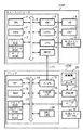
図1は本発明の実施形態を示すプリンタ制御システム(印刷システム)におけるホストコンピュータとプリンタの構成を説明するブロック図である。なお、本発明の機能が実行されるのであれば、単体の機器であっても、複数の機器からなるシステムであっても、LAN,WAN等のネットワークを介して接続がなされ処理が行われるシステムであっても本発明を適用できる。
【0022】
図1において、ホストコンピュータ3000は、ROM3のプログラム用ROMあるいは外部メモリ11に記憶された文書処理プログラム等に基づいて図形、イメージ、文字、表(表計算等を含む)等が混在した文書処理を実行するCPU1を備え、システムバス4に接続される各デバイスをCPU1が総括的に制御する。
【0023】
また、このROM3のプログラム用ROMあるいは外部メモリ11は、CPU1の制御プログラムであるオペレーティングシステムプログラム(以下OS)等を記憶し、ROM3のフォント用ROMあるいは外部メモリ11には上記文書処理の際に使用するフォントデータ等を記憶し、ROM3のデータ用ROMあるいは外部メモリ11には上記文書処理等を行う際に使用する各種データを記憶する。RAM2は、CPU1の主メモリ、ワークエリア等として機能する。
【0024】
キーボードコントローラ(KBC)5は、キーボード9や不図示のポインティングデバイスからのキー入力を制御する。CRTコントローラ(CRTC)6は、CRTディスプレイ(CRT)10の表示を制御する。7はディスクコントローラ(DKC)で、ブートプログラム、各種のアプリケーション、フォントデータ、ユーザーファイル、編集ファイル、プリンタ制御コマンド生成プログラム(以下プリンタドライバ)等を記憶するハードディスクHD、フロッピー(登録商標)ディスクFD等の外部メモリ11とのアクセスを制御する。プリンタコントローラ(PRTC)8は、双方向性インタフェイス(インタフェイス)21を介してプリンタ1500に接続されて、プリンタ1500との通信制御処理を実行する。
【0025】
なお、CPU1は、例えばRAM2上に設定された表示情報RAMへのアウトラインフォントの展開(ラスタライズ)処理を実行し、CRT10上でのWYSIWYGを可能としている。また、CPU1は、CRT10上の不図示のマウスカーソル等で指示されたコマンドに基づいて登録された種々のウインドウを開き、種々のデータ処理を実行する。
【0026】
ユーザーは印刷を実行する際、印刷の設定に関するウインドウを開き、プリンタの設定や、印刷モードの選択を含むプリンタドライバに対する印刷処理方法の設定を行える。図18は、タブ紙の両面印刷を行う時の、ホストコンピュータ3000におけるCRTディスプレイ10に表示されるGUIの例を示したものである。図18に示すGUIでは、タブ紙のPrint Styleとして両面印刷(2−sidedPrinting)、給紙部23のタブ紙を給紙する給紙段としてDrawer3、タブ紙の挿入位置として、3ページ目と6ページ目が選択されている。
【0027】
図1においてプリンタ1500は、CPU12により制御される。プリンタCPU12は、ROM13のプログラム用ROMに記憶された制御プログラム等あるいは外部メモリ14に記憶された制御プログラム等に基づいてシステムバス15に接続される印刷部(プリンタエンジン)17に出力情報としての画像信号を出力する。
【0028】
また、このROM13のプログラムROMには、CPU12の制御プログラム等を記憶する。ROM13のフォント用ROMには上記出力情報を生成する際に使用するフォントデータ等が記憶され、ROM13のデータ用ROMには、ハードディスク等の外部メモリ14がないプリンタの場合には、ホストコンピュータ上で利用される情報等が記憶されている。
【0029】
CPU12は入力部18を介してホストコンピュータとの通信処理が可能となっており、プリンタ内の情報等をホストコンピュータ3000に通知できる。RAM19は、CPU12の主メモリや、ワークエリア等として機能するRAMで、図示しない増設ポートに接続されるオプションRAMによりメモリ容量を拡張することができるように構成されている。なお、RAM19は、出力情報展開領域、環境データ格納領域、NVRAM等に用いられる。
【0030】
前述したハードディスク(HD)、ICカード等の外部メモリ14は、メモリコントローラ(MC)20によりアクセスを制御される。外部メモリ14は、オプションとして接続され、フォントデータ、エミュレーションプログラム、フォームデータ等を記憶する。また、22はユーザーインタフェイスで、後述するワーニングメッセージを表示するための表示画面(この表示画面はタッチパネル式であってもよい)、各種操作のためのスイッチ、印刷装置に対してプリント命令を出すためのOKボタン及びLED表示器等が配されている。
【0031】
また、前述した外部メモリ14は1個に限らず、複数個備えられ、内蔵フォントに加えてオプションカード、言語系の異なるプリンタ制御言語を解釈するプログラムを格納した外部メモリを複数接続できるように構成されていてもよい。更に、図示しないNVRAMを有し、ユーザーインタフェイス22からのプリンタモード設定情報を記憶するようにしてもよい。
【0032】
印刷部17は、電子写真方式やインクジェット方式などにより印刷処理を行うものであり、例えば電子写真方式の場合であれば、像担持体たる感光ドラム、感光ドラムの周囲を所定の極性・電位に一様に帯電処理するための帯電ローラ、感光ドラムの一様に帯電された表面を走査露光し、静電潜像を形成するためのレーザービームスキャナー等の画像情報露光部、感光ドラム上の静電潜像をトナー像として現像するための現像部、感光ドラム上に形成されたトナー像を給紙部23から給紙される記録紙に対して順次静電転写するための転写ローラ、トナー像を記録紙に定着させるための定着部、トナー像が定着された記録紙を排出する排出部などで主に構成される。
【0033】
給紙部23は、タブ紙を含む記録紙を収容する収容部である手差しトレイやカセット等の複数の給紙段により構成され、各給紙段には、記録紙の有無を検知するためのセンサ24を備えている。
【0034】
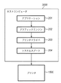
図2は、プリンタ等の印刷装置が直接接続されているか、あるいはネットワーク経由で接続されているホストコンピュータにおける典型的な印刷処理のための、ソフトウエアモジュール構成の一例を示す図である。アプリケーション201、グラフィックエンジン202、プリンタドライバ203、およびシステムスプーラ204は、外部メモリ11に保存されたファイルとして存在し、実行される場合にOSやそのモジュールを利用するモジュールによってRAM2にロードされ実行されるプログラムモジュールである。また、アプリケーション201およびプリンタドライバ203は、外部メモリ11のFDや不図示のCD−ROM、あるいは不図示のネットワークを経由して外部メモリ11のHDに追加することが可能となっている。
【0035】
外部メモリ11に保存されているアプリケーション201はRAM2にロードされて実行されるが、このアプリケーション201からプリンタ1500に対して印刷を行う際には、同様にRAM2にロードされ実行可能となっているグラフィックエンジン202を利用して出力(描画)を行う。
【0036】
グラフィックエンジン202は、印刷装置ごとに用意されたプリンタドライバ203を同様に外部メモリ11からRAM2にロードし、アプリケーション201の出力をプリンタドライバ203に設定する。そして、アプリケーション201から受け取るGDI(Graphic Device Interface)関数をDDI(Device Driver Interface)関数に変換して、プリンタドライバ203にDDI関数を出力する。
【0037】
プリンタドライバ203は、グラフィックエンジン202から受け取ったDDI関数をプリンタが認識可能な制御コマンド、例えばPDL(Page DescriptionLanguage)に変換する。変換されたプリンタ制御コマンドは、OSによってRAM2にロードされたシステムスプーラ204を経てインタフェイス21経由でプリンタ1500へ印刷データとして出力される仕組みとなっている。
【0038】
本実施形態の印刷システムは、図1で示すプリンタとホストコンピュータからなる印刷システムに加えて、更に図2に示すように、アプリケーションからの印刷データを一旦中間コードデータとしてスプールする構成を有する。
【0039】
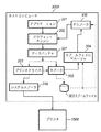
<本実施形態における印刷関連のソフトウエアモジュール>
図3は、図2のシステムを拡張したソフトウエアモジュール構成を示す図である。図3においては、グラフィックエンジン202からプリンタドライバ203へ印刷命令を送る際に、一旦中間コードからなるスプールファイル303が生成される。図2のシステムでは、アプリケーション201が印刷処理から開放されるのはプリンタドライバ203がグラフィックエンジン202からの印刷命令の全てをプリンタの制御コマンドへ変換し終った時点である。
【0040】
これに対して、図3のシステムでは、スプーラ302がすべての印刷命令を中間コードデータに変換し、スプールファイル303に出力した時点で、アプリケーション201は解放される。通常、後者の方が短時間で済む。
【0041】
また、図3に示すモジュール構成では、スプールファイル303の内容に対して加工を行うことができる。これによりアプリケーションからの印刷データに対して、本発明のタブ紙印刷をはじめ、拡大縮小や、複数ページを1ページに縮小して印刷する等、アプリケーションの持たない機能を実現することができる。
【0042】
なお、印刷データの加工を行うためには、通常プリンタドライバ203が提供するウインドウから設定を行い、プリンタドライバ203がその設定内容をRAM2上あるいは外部メモリ11上に保管する。
【0043】
以下、図3の詳細を説明する。図に示す通り、この拡張された処理方式では、グラフィックエンジン202からの印刷命令であるDDI関数をディスパッチャ301が受け取る。ディスパッチャ301がグラフィックエンジン202から受け取った印刷命令(DDI関数)が、アプリケーション201からグラフィックエンジン202へ発行された印刷命令(GDI関数)に基づくものである場合には、ディスパッチャ301は外部メモリ11に格納されているスプーラ302をRAM2にロードし、プリンタドライバ203ではなくスプーラ302へ印刷命令(DDI関数)を送る。
【0044】
スプーラ302は受け取った印刷命令を解析し、ページ単位に中間コードに変換してスプールファイル303に出力する。このページ単位に格納されている中間コードのスプールファイル303をページ描画ファイル(PDF:Page DescriptionFile)と呼ぶ。
【0045】
また、スプーラ302は、プリンタドライバ203に対して設定されている印刷データに関する加工設定(Nup、タブ紙印刷、両面、ステイプル、カラー/モノクロ指定等)をプリンタドライバ203から取得してジョブ単位のファイルとしてスプールファイル303に保存する。この時部単位に格納されている設定ファイルをジョブ設定ファイル(簡略してSDF:Spool Description Fileと呼ぶこともある)と呼ぶ。
【0046】
このジョブ設定ファイルについては後述する。なお、スプールファイル303は外部メモリ11上にファイルとして生成されるが、RAM2上に生成されても構わない。更にスプーラ302は、外部メモリ11に格納されているスプールファイルマネージャ304をRAM2にロードし、スプールファイルマネージャ304に対してスプールファイル303の生成状況を通知する。その後、スプールファイルマネージャ304は、スプールファイル303に保存された印刷データに関する加工設定の内容に従って印刷を行えるかを判断する。
【0047】
スプールファイルマネージャ304がグラフィックエンジン202を利用して印刷を行えると判断した際には、外部メモリ11に格納されているデスプーラ305をRAM2にロードし、デスプーラ305に対して、スプールファイル303に記述された中間コードのページ描画ファイルの印刷処理を行うように指示する。
【0048】
デスプーラ305はスプールファイル303に含まれる中間コードのページ描画ファイルをスプールファイル303に含まれる加工設定情報を含むジョブ設定ファイルに従って加工し、GDI関数を再生成し、もう一度グラフィックエンジン202経由でGDI関数を出力する。
【0049】
ディスパッチャ301がグラフィックエンジン202から受け取った印刷命令(DDI関数)がデスプーラ305からグラフィックエンジン202へ発行された印刷命令(GDI関数)に基づいたものである場合には、ディスパッチャ301はスプーラ302ではなく、プリンタドライバ203に印刷命令を送る。
【0050】
プリンタドライバ203はグラフィックエンジン202から取得したDDI関数に基づいてページ記述言語等からなるプリンタ制御コマンドを生成し、システムスプーラ204経由でプリンタ1500に出力する。
【0051】
<印刷用中間データの保存処理>
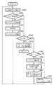
図5は、スプーラ302における、スプールファイル303の生成におけるページ単位保存ステップの処理をフローチャートで示したものである。
【0052】
まずステップ501では、スプーラ302は、アプリケーションからグラフィックエンジン202を介して印刷要求を受けつける。アプリケーションにおいては、印刷設定を入力するダイアログが表示され、このダイアログから入力された印刷設定がプリンタドライバよりスプーラ303に渡される。
【0053】
ステップ502では、スプーラ302は、受け付けた印刷要求がジョブ開始要求か否かを判定し、もしジョブ開始要求であると判定した場合には、ステップ503に進み、スプーラ302は、中間データを一時的に保存するためのスプールファイル303を作成する。続いて、ステップ504では、スプーラ302は、スプールファイルマネージャ304へ印刷処理の進捗を通知し、続くステップ505でスプーラ302のページ数カウンタを1に初期化する。
【0054】
ここで、スプールファイルマネージャ304においては、印刷が開始されたジョブに対するジョブの情報や加工設定などをスプールファイル303より読み込み、記憶する。
【0055】
一方、ステップ502において、ジョブ開始要求ではなかったと判定した場合には、ステップ506に進む。ステップ506では、スプーラ302は受け付けた要求がジョブ終了要求かどうかの判定を行う。ジョブ終了要求でないと判定した場合には、ステップ507に進み、改ページかどうかの判定を行う。
【0056】
もしもステップ507で改ページであると判定した場合には、ステップ508に進み、スプールファイルマネージャ304へ印刷処理の進捗を通知する。そしてページ数カウンタをインクリメントして、中間コードを格納しているページ描画ファイルを閉じ、次のページ描画ファイルを生成する。
【0057】
ステップ507において、受け付けた印刷要求が改ページではないと判定した場合にはステップ509に進み、スプーラ302はページ描画ファイルへの中間コードの書き出しの準備を行う。次に、ステップ510では、印字要求をスプールファイル303へ格納するため、スプーラ302は、印字要求のDDI関数の中間コードへの変換処理を行う。ステップ511では、スプーラ302は、ステップ510において格納可能な形に変換された印刷要求(中間コード)をスプールファイル303のページ描画ファイルへ書き込む。
【0058】
その後、ステップ501に戻り、再びアプリケーションからの印刷要求を受けつける。この一連のステップ501からステップ511までの処理を、アプリケーションよりジョブ終了要求(End Doc)を受け取るまで続ける。また、スプーラ302は、同時にプリンタドライバ203からDEVMODE構造体に格納されている加工設定等の情報を取得し、ジョブ設定ファイルとしてスプールファイル303に格納する。
【0059】
一方、ステップ506にて、アプリケーションからの印刷要求がジョブ終了であると判定した場合には、アプリケーションからの印刷要求は全て終了であるので、ステップ512に進み、スプールファイルマネージャ304へ印刷処理の進捗を通知し、処理を終える。
【0060】
<スプールファイルの生成>
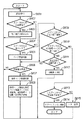
図6は、スプールファイルマネージャ304における、スプールファイル303生成プロセスと、後述する印刷データ生成プロセスの間での制御の詳細をフローチャートで示したものである。
【0061】
ステップ601では、スプールファイルマネージャ304は、スプーラ302又はデスプーラ305からの印刷処理の進捗通知を受け付ける。ステップ602では、スプールファイルマネージャ304は、進捗通知が前述のステップ504において通知されるスプーラ302からの印刷開始通知であるかどうか判定し、もしそうであればステップ603へ進み、印刷の加工設定をスプールファイル303から読み込み、ジョブの管理を開始する。
【0062】
本発明におけるタブ紙印刷の設定は、スプールファイル303に格納され、ステップ603においてスプールファイルマネージャ304が読み込み可能となる。
【0063】
一方、ステップ602において、スプーラ302からの印刷開始通知でないと判定した場合はステップ604へ進み、スプールファイルマネージャ304は、進捗通知が前述のステップ508において通知されるスプーラ302からの1論理ページの印刷終了通知であるかどうか判定する。ここで1論理ページの印刷終了通知であればステップ605へ進み、この論理ページに対する論理ページ情報を格納する。
【0064】
そして、続くステップ606では、この時点でスプールが終了したn論理ページに対して、1物理ページの印刷が開始できるかを判定する。ここで、印刷可能である場合はステップ607へ進み、印刷する1物理ページに対して割り付けれられる論理数から物理ページ番号を決定する。
【0065】
物理ページの計算については、例えば、加工設定が1物理ページに4論理ページを配置するような設定の場合、第1物理ページは第4論理ページがスプールされた時点で印刷可能となり、第1物理ページとなる。続いて、第2物理ページは第8論理ページがスプールされた時点で印刷可能となる。
【0066】
また、論理ページ数の総数が1物理ページに配置する論理ページ数の倍数でなくても、ステップ512におけるスプール終了通知によって1物理ページに配置する論理ページが決定可能である。ただし、本実施形態においては、タブ紙印刷であるので、1物理ページに配置される論理ページの数は1となる。
【0067】
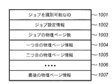
そして、ステップ608では、図8に示すような形式で印刷可能となった物理ページを構成する論理ページ番号と、その物理ページ番号などの情報がジョブ出力用設定ファイル(物理ページ情報を含むファイル)に保存され、物理ページ情報が1物理ページ分追加されたことがデスプーラ305に通知される。
【0068】
その後ステップ601に戻り、次の通知を待つ。本実施形態においては、印刷データ1ページ、即ち1物理ページを構成する論理ページがスプールされた時点で印刷ジョブのスプールが全て終了していなくても印刷処理が可能である。
【0069】
一方、ステップ604において、進捗通知がスプーラ302からの1論理ページの印刷終了通知でなかった場合はステップ609へ進み、スプールファイルマネージャ304は、前述のステップ512において通知されるスプーラ302からのジョブ終了通知であるかどうかを判定する。ここで、ジョブ終了通知である場合、前述のステップ606へ進む。一方、ジョブ終了通知でない場合、ステップ610へ進み、スプールファイルマネージャ304は、受け付けた通知がデスプーラ305からの1物理ページの印刷終了通知であるかどうか判定する。
【0070】
ここで、1物理ページの印刷終了通知である場合はステップ612へ進み、加工設定の印刷が全て終了したかを判定する。印刷終了した場合、ステップ612へ進み、デスプーラ305に印刷終了の通知を行う。一方、加工設定に対する印刷がまだ終了していないと判断した場合、前述の606へ進む。
【0071】
本実施形態におけるデスプーラ305は印刷処理を行う単位として1物理ページ数を想定している。また、ステップ608では、1物理ページの印刷処理を行うのに必要な情報をファイルに逐次保存し、再利用可能な形式にしているが、再利用不要な場合には、共有メモリ等高速な媒体を使用し、1物理ページ単位で次々と上書きする実装にして、速度とリソースを節約するような実装形式であってもよい。
【0072】
また、デスプールの進捗よりもスプールの進捗の方が早い場合や全ページのスプール終了後からデスプールが開始されるような場合には、ステップ608で1物理ページ毎にページ印刷可能を通知せずに、デスプール側の進捗に応じて、複数物理ページもしくは全物理ページが印刷可能になったという通知内容にして、通知回数を節約することが可能である。
【0073】
ステップ610において、通知がデスプーラ305からの1物理ページの印刷終了通知でないと判断された場合、ステップ613へ進み、スプールファイルマネージャ304は、デスプーラ305からの印刷終了通知かどうかを判定する。通知がデスプーラ305からの印刷終了通知と判定された場合、ステップ614へ進み、スプールファイルマネージャ304は、スプールファイル303の該当するページ描画ファイルの削除を行い処理を終える。ただし、一方、デスプーラ305からの印刷終了通知でなかった場合はステップ615へ進み、その他通常処理を行い、次の通知を待つ。
【0074】
<スプールファイルの出力>
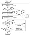
図7は、デスプーラ305における、印刷データの生成プロセスの詳細をフローチャートで示したものである。
【0075】
デスプーラ305は、スプールファイルマネージャ304からの印刷要求に応じて、スプールファイル303から必要な情報(ページ描画ファイルおよびジョブ設定ファイル)を読み出して印刷データを生成する。生成された印刷データにおけるプリンタへの転送方法については図3で説明した通りである。
【0076】
印刷データの生成では、まず、ステップ701において、前述のスプールファイルマネージャ304からの通知を受け付ける。続くステップ702では、デスプーラ305は、受け付けた通知がジョブの終了通知かどうか判定し、ジョブ終了通知であるならばステップ703へ進み、終了フラグを立て、ステップ705へ進む。
【0077】
一方、ステップ702においてジョブ終了通知でないと判定した場合は、ステップ704に進み、前述のステップ608における1物理ページの印刷開始要求が通知されたかどうか判定する。ステップ704において開始要求と判定されなかった場合は、ステップ710へ進み、その他エラー処理を行い、ステップ701へ戻り次の通知を待つ。
【0078】
一方、ステップ704において1物理ページの印刷開始要求と判定された場合は、ステップ705へ進み、デスプーラ305は、ステップ704で通知を受けた印刷処理可能な物理ページのIDを保存する。続くステップ706では、デスプーラ305は、ステップ705で保存した物理ページIDのすべてのページに関して印刷処理が終了しているかどうか判定する。
【0079】
ここで全物理ページの処理が済んでいる場合は、ステップ707へ進み、前述のステップ703で終了フラグが立てられているのか判定する。終了フラグがたっている場合はジョブの印刷が終了したとみなし、デスプーラ305の処理終了の通知をスプールファイルマネージャ304に通知して処理を終える。ステップ707で、終了フラグが立っていないと判定された場合は、ステップ701へ戻り次の通知を待つ。一方、ステップ706で印刷可能な物理ページが残っていると判定された場合には、ステップ708へ進み、デスプーラ305は、保存された物理ページIDから未処理の物理ページIDを順に読み出し、読み出した物理ページIDに対応する物理ページの印刷データ生成に必要な情報を読み込み印刷処理を行う。
【0080】
印刷処理では、スプールファイル303に格納された印刷要求命令を、デスプーラ305においてグラフィックエンジン202が認識可能な形式(GDI関数)に変換して転送する。本実施形態のような、複数論理ページを1物理ページにレイアウトするような加工設定(以下Nページ印刷)については、このステップで縮小配置を考慮しながら変換する。
【0081】
必要な印刷処理が終えたならば、続くステップ709において1物理ページの印刷データ生成終了の通知をスプールファイルマネージャ304に対して行う。そして再びステップ706へ戻り、ステップ705で保存しておいた印刷可能な物理ページIDすべてについて印刷処理を行うまで繰り返す。
【0082】
以上が、ディスパッチャ301、スプーラ302、スプールファイルマネージャ304、デスプーラ305を用いた印刷処理の流れである。上記のように処理することにより、スプーラ302が中間コードを生成してスプールファイル303に格納するタイミングでアプリケーション201が印刷処理から開放されるので、プリンタドライバ203に直接出力するよりも短時間で済む。
【0083】
<ジョブ出力用設定ファイルの構成>
図10は、ステップ608において、スプールファイルマネージャ304が生成する印刷可能となった物理ページを構成する情報を保存しているジョブ出力用設定ファイルの例を示す。フィールド1001は、ジョブを識別するためのIDで、本情報を保存しているファイル名や共有メモリの名称という形で保持することも可能である。フィールド1002はジョブ設定情報である。
【0084】
ジョブ設定情報には、グラフィックエンジン202に対してジョブの印刷を開始するために必要な構造体、本発明のタブ紙印刷の設定、Nページ印刷の指定、ページ枠などの追加描画の指定、部数、ステイプルなどのフィニッシング指定など、1つのジョブに対して1つしか設定できない情報が含まれている。ジョブ設定情報1002には、ジョブに対する機能に応じて必要なだけ情報が保存される。
【0085】
フィールド1003はジョブの物理ページ数で、本フィールド以降、この数の分だけ物理ページ情報が保存されていることを示す。本実施形態では、印刷可能な物理ページ数を通知する方式であるので、このフィールドは無くても動作可能である。これ以降、フィールド1004から最後までフィールド1003の数だけ物理ページ情報が格納される。物理ページ情報については図12で説明する。
【0086】
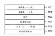
図11は、図10のフィールド1002に図示されたジョブ設定情報の一例である。フィールド1101は全物理ページ数である。フィールド1102は、全論理ページ数である。フィールド1101および1102は、印刷データに追加して、ページ数などを付加情報として印刷する場合などに利用する。印刷が続いている際には、両フィールドは暫定的な値、もしくは、印刷が終了するまでスプールファイルマネージャ304は印刷可能な物理ページの情報の作成を延期する。
【0087】
フィールド1103は本印刷ジョブを何部印刷するかを指定する部数情報である。フィールド1104は、フィールド1103で複数部印刷する設定の場合、部単位で印刷するかどうかの指定である。フィールド1104はステイプル、パンチ、Z折などのフィニッシング情報で、プリンタ本体もしくは外部にフィニッシャーがある場合に指定される。
【0088】
フィールド1106は付加印刷情報で、ページ枠などの飾り、日付などの付加情報、ユーザー名、ページ数、ウォーターマーク印刷等、ジョブに対して付加する情報が保存される。機能が増えるに従って本ジョブ設定情報に含まれるフィールドの数も増加し、例えば、両面印刷が可能な場合は、両面印刷の指定を保存するフィールドが追加される。
【0089】
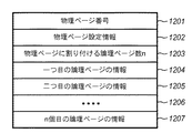
図12は、図10のフィールド1004に図示された物理ページ情報の一例を示す。最初のフィールド1201は物理ページ番号で、印刷順序の管理や、物理ページ番号を追加印刷する際に使用される値である。フィールド1202は物理ページ設定情報で、物理ページ毎にレイアウトやカラー・モノクロの指定が可能である場合、レイアウトやカラー・モノクロの設定が保存される。
【0090】
フィールド1203は本物理ページに割り付けられる論理ページ数で、1物理ページに4ページを割り付ける場合には4もしくは4ページ印刷を示すIDが保存される。フィールド1204以降はフィールド1203で指定された数だけ論理ページの情報が保存される。
【0091】
アプリケーション201から印刷されたページ数によっては、1203で指定されるページ数よりも実際のページデータ数が少なくなる場合がある。その場合には、論理ページ情報に空ページを示す特別なデータを保存して対応する。ただし、本発明のタブ紙印刷においては、1物理ページ中の論理ページ数は1となる。
【0092】
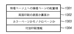
図13は、1202の物理ページ設定情報の例である。フィールド1301は物理ページ上への論理ページの配置順で、Nページ印刷で、物理ページ上に論理ページを配置する順番(左上から横へ、左上から下へ等)の指定が保存されている。システムによっては、配置順ではなく、フィールド1204以降の論理ページ情報の順番をページ番号順ではなく、配置順に応じた順序で配することで1301の設定を代用する場合もある。
【0093】
フィールド1302は両面印刷の表・裏の情報が格納される。本発明においては、タブ紙の表面を始めに印刷し、その後、タブの裏面に対する印刷を行うが、タブ表面の印刷時には表面をあらわす値が格納され、タブ裏面に対する印刷の際は裏面を表す値が代入されることになる。
【0094】
その他、例えば綴じ代を表裏でそろえる際に使用される。フィールド1303はカラーページかモノクロページかの指定で、プリンタがモノクロモードとカラーモードを持つ場合、カラーページとモノクロページが混在する文書で、カラーページをカラーモードで、モノクロページをモノクロモードで印刷したい場合などに使用される値である。
【0095】
この情報を持つことにより、オートカラーモードとして、ページ単位にカラープリンタで処理を変更することが可能となる。つまり、カラーページは、中間転写体(中間転写ドラム、中間転写ベルト)もしくは転写体(転写ドラム、転写ベルト)がデバイスカラーの数分、YMCKなら4回転し、モノクロページは、ブラックだけ1回転することにより転写制御することを可能とする。
【0096】
フィールド1304は付加印刷情報で、物理ページに対して、ページ数や、日付などの付加情報を印刷する場合に使用される。物理ページ設定情報も、システムの機能に応じてフィールドが追加される。
【0097】
図14は、1204で示された論理ページ情報の一例を示す。フィールド1401は論理ページのIDで、このIDを利用して、スプールファイル303から論理ページに対応するページ描画ファイルの中間コードを参照する。このIDを利用して論理ページの中間コードへアクセス可能であれば良く、ファイルやメモリポインタであっても、論理ページを構成する中間コード自身が入っていてもよい。
【0098】
フィールド1402は論理ページ番号で論理ページ番号を付加情報として印刷する場合や、論理ページIDの補助情報に使用される。フィールド1403のフォーマット情報には、論理ページ単位で指定可能である各種設定項目が保存される。例えば、ページ枠などの付加印刷情報、拡縮率などの論理ページ単位に指定される各種設定の情報が保存される。また、必要であれば、論理ページ単位のカラー・モノクロ情報などの論理ページに対する属性情報を保存する事も可能である。逆に、論理ページ単位で設定を切りかえる事や論理ページ単位での属性情報が不要であるようなシステムでは、フィールド1403は不要である。
【0099】
ジョブ出力用設定ファイルは、上記のように構成されている。なお、ジョブ設定ファイルもほぼ同様であり、印刷体裁(片面、両面、製本印刷)、印刷レイアウト(タブ紙印刷、Nup、ポスター印刷)、付加情報(ウォーターマーク、日付、ユーザー名の付加)、部数、用紙サイズ情報がジョブとして有しており、物理ページ毎に、論理ページの配置順、両面印刷の表面か、裏面か、カラーモード等から構成されている。
【0100】
<単一原稿でタブ紙への両面印刷を実現するための処理>
以下に、単一原稿でタブ紙への両面印刷を実現するための処理について、詳細に説明する。
【0101】
まず、5タブ用紙の両面タブ印刷の場合を例にとって、スプールファイルマネージャ304の動作を説明する。スプールファイルマネージャ304においては、図6のステップ607およびステップ608において、印刷する物理ページ情報が生成される。5タブ用紙の両面印刷の例では、10物理ページ分の印刷データが生成される。内訳は、第1物理ページから第5物理ページまでは、図13におけるフィールド1302に表面を示す値が格納される。
【0102】
また、第6物理ページから第10物理ページは、裏面用の印刷データとなるので、フィールド1302には裏面を示す値が格納される。また、第6物理ページから第10物理ページについては、図6におけるステップ609(スプーラ302からのスプール終了通知)において、印刷に必要なページ数が決定された時点で生成される。
【0103】
図8は、タブ紙原稿における描画データについて説明した図である。通常、タブ紙原稿は、A4あるいはレターの原稿サイズの有効印字領域801内において、各ページにおけるタブ原稿を用意するのが一般的である。つまり、5タブ用の原稿であれば5ページ、10タブ用の原稿であれば10ページ分用意されることになる。
【0104】
まず、有効印字領域における原点(X0,Y0)に対して、タブ部に印刷されるデータの基準座標が(X1,Y1)であることを示している。本実施形態のようなテキストデータの場合、座標は文字列の基準値が用いられるのが一般的であるが、基準値は本発明を実現するプログラムが動作するOS仕様により、文字列矩形の左上/左下であったり、文字デザインのベースラインであったりと異なるが、本発明において特に制限とするところではない。
【0105】
また、タブ印刷を行う場合には、原稿に対するオフセット値 offset_xを印刷装置が認識することにより、原稿に対してoffset_xの数値分だけ印刷原稿がオフセットされ、タブの部分に印刷される。このoffset_xは本発明におけるプログラムにおいてユーザーインタフェイスを持つことによって設定可能な値であってもよいし、また、印刷装置(プリンタ)が提供するユーザーインタフェイスから設定可能でも良い。あるいは、印刷装置固有の固定値であってもよい。
【0106】
したがって、タブ紙原稿印刷においては、各ページに配置するオブジェクトの座標と、オフセット値を独立に考慮してよい。図8では、1ページ目のタブ原稿を示しているが、2ページ目以降、図9に示すようにoffset_x分のシフトで各タブに収まるように配置され、用意される。
【0107】
図15は、タブ紙の裏面に印刷される際の座標計算について、第1ページと第5ページの座標変換について説明する図である。タブの数すなわち原稿の総ページ数をn、現在印刷しようとしている原稿が第kページであるとすると、裏面に対する印刷データのオフセット値 offset_y は以下の式により計算することができる。
【0108】
【数1】
Offset_y = Y(n+1−k) − Y(k)
ここで、Y(k)は、第k物理ページに格納されている印刷オブジェクトのY座標値を示す。すなわちデスプーラ307における描画処理(図7におけるステップ708)の際、描画データのY座標に対して、上記調整値を加味しながら印刷データを生成することになる。
【0109】
図15の場合はOffset_y = Y(5+1−5) − Y(5)となるので、TAB1のY座標値からTAB5のY座標値を引いた値がオフセット値となり、デスプーラ307における描画処理では、1501分だけTAB5の描画データをずらして印刷データを生成することになる。
【0110】
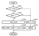
図16は、デスプーラ305における図7のステップ708における処理を示すフローチャートである。
【0111】
まず、ステップ1601においては、図18に対応するユーザー設定に基づいてタブ紙印刷の設定が為されているか否かを判定する。もし、タブ紙印刷でなく通常の記録紙印刷であればステップ1603へ進み描画データを生成した後、ステップ1604にて記録紙に対する印刷処理をおこなう。
【0112】
一方、ステップ1601においてタブ紙印刷と判定されればステップ1602へ進み、印刷処理を行う物理ページが表面かどうかを判定する。もし、表面ならばスプーラ305における処理は記録紙印刷と変わりがないので、ステップ1603へ進んで通常の印刷処理を行う。この場合ステップ1603では、上記の図8、図9に相当する描画データの生成を行う。
【0113】
一方、ステップ1602で裏面と判定された場合はタブ紙裏面印刷を行うためにステップ1605へ進む。このステップ1605では、前述の式1により、Offset_yを計算する。次に、ステップ1606において、Offset_y分だけ移動させた座標値において描画データを生成し、それに基づいて印刷処理を行う。
【0114】
以上の処理によって、単一原稿でタブ紙への両面印刷を実現することが可能となる。
【0115】
【第2の実施形態】
第1の実施形態では、単一オブジェクトかつテキストデータを想定したが、タブの印刷領域は用紙依存であるので、データに関係することなく、用紙サイズおよびタブの数から一定の値をオフセット値として算出する方法により、テキストデータ以外のオブジェクトや、複数のオブジェクトを扱うことが可能である。
【0116】
具体的には、実施形態1におけるOffset_yの計算において、Y(k)の値が印刷データではなく、図17のように、タブ用紙自体のY軸方向における領域を示す座標値Y(pk)を使用することで実現される。
【0117】
図17では、5タブの例を示しているので、Y(p1)からY(p5)までが存在する。具体的な計算方法としては、タブ数n、用紙サイズの情報Lyとすると、k番目のタブ(k)の基準座標Y(pk)と、オフセット値Offset_yは、以下の式で算出される。
【0118】
【数2】
Y(pk) = (k −1) * Ly / n
【数3】
Offset_y = Y(p(n+1−k)) − Y(pk)
上式3によって求められたOffset_yを第1の実施形態で示した処理に使用することにより、同様に単一原稿でタブ紙への両面印刷を実現することが可能となる。
【0119】
【他の実施の形態】
なお、本発明の目的は、前述した実施形態の機能を実現する手順を実現するプログラムコードを記憶した記憶媒体を、システムあるいは装置のコンピュータ(またはCPUやMPU)が記憶媒体に格納されたプログラムコードを読出し実行することによっても達成される。
【0120】
この場合、記憶媒体から読み出されたプログラムコード自体が前述した実施形態の機能を実現することになり、そのプログラムコードを記憶した記憶媒体は本発明を構成することになる。
【0121】
プログラムコードを供給するための記憶媒体としては、例えば、フロッピー(登録商標)ディスク、ハードディスク、光ディスク、光磁気ディスク、CD−ROM、CD−R、DVD−ROM、DVD−R、磁気テープ、不揮発性のメモリカード、ROM、ネットワーク上のファイルサーバが有する記憶装置、或いは、インターネット上のFTPサーバが有する記憶装置など、あらゆる記録媒体を用いることができる。
【0122】
また、コンピュータが読み出したプログラムコードを実行することにより、前述した実施形態の機能が実現されるだけでなく、そのプログラムコードの指示に基づき、コンピュータ上で稼動しているOS(オペレーティングシステム)などが実際の処理の一部または全部を行い、その処理によって前述した実施形態の機能が実現される場合も含まれる。
【0123】
【発明の効果】
以上のように、本発明によれば、表面用のタブレイアウトと、裏面用のタブレイアウトの2種類を用意することなく、単一レイアウトに基づいてタブ紙の両面印刷を行うことができ、ユーザーの所望するタブ紙印刷制御方法を提供可能となる。
【図面の簡単な説明】
【図1】本発明の実施形態における印刷システムの構成を説明するブロック図である。
【図2】ホストコンピュータにおける印刷処理のためのソフトウエアモジュール構成の一例を示す図である。
【図3】ホストコンピュータにおける印刷処理のためのソフトウエアモジュール構成の他の一例を示す図である。
【図4】用紙搬送方向と、タブ原稿向きの関係を示す図である。
【図5】スプーラ302における処理を示したフローチャートである。
【図6】スプールファイルマネージャ304における印刷制御について示したフローチャートである。
【図7】デスプーラ305における処理を示したフローチャートである。
【図8】タブ紙原稿における描画データについて説明した図である。
【図9】2ページ目のタブ原稿の一例である。
【図10】スプールファイルマネージャ304からデスプーラ305に対して物理ページの印刷要求を行う際に渡すデータ形式の一例を示した図である。
【図11】スプールファイルマネージャ304からデスプーラ305に対して物理ページの印刷要求を行う際に渡すデータ形式の一例を示した図である。
【図12】スプールファイルマネージャ304からデスプーラ305に対して物理ページの印刷要求を行う際に渡すデータ形式の一例を示した図である。
【図13】スプールファイルマネージャ304からデスプーラ305に対して物理ページの印刷要求を行う際に渡すデータ形式の一例を示した図である。
【図14】スプールファイルマネージャ304からデスプーラ305に対して物理ページの印刷要求を行う際に渡すデータ形式の一例を示した図である。
【図15】本発明の実施形態におけるタブ紙の裏面に印刷される際の座標計算について、第1ページと第5ページの座標変換について説明する図である。
【図16】デスプーラ305の図7ステップ708内の処理を示すフローチャートである。
【図17】第2の実施形態における、裏面タブ印刷の際に使用するオフセット値を示す図である。
【図18】タブ紙の両面印刷を行う場合のGUIの例を示したものである。
【符号の説明】
1 CPU
2 RAM
3 ROM
4 システムバス
12 CPU
13 ROM
19 RAM
3000 ホストコンピュータ
1500 プリンタ[0001]
TECHNICAL FIELD OF THE INVENTION
The present invention relates to a printing control apparatus, a tab sheet double-sided printing method, a program, and a storage medium, and more particularly to generation of tabs and printing control in a system including an information processing apparatus such as a personal computer and a printer.
[0002]
[Prior art]
Tab paper is A4 or letter paper with 'tabs' indicating items and titles. It is called 10 tab paper with 10 tabs or 5 tab paper with 5 tabs. Is a typical tab sheet. The tab portion is typically 1/2 inch in the case of a letter, but there is also a tab sheet having tabs of other sizes. Printing on tab paper is not supported due to the fact that tabs are attached compared to ordinary paper, and thick paper is usually used for tab paper, and conventional printers cause paper jams in the transport system. Things are mostly. However, in recent years, tab paper printing by a printing apparatus can be performed by improving the technology of a paper conveyance system (see Patent Document 1 below). Along with this, in a printing apparatus having a printer function called a multi-function device, a tab created on a computer can be printed via a printer driver.
[0003]
[Patent Document 1]
JP-A-10-67458
[0004]
[Problems to be solved by the invention]
However, although printing of tab paper can be performed by a printing apparatus, this is only for single-sided printing, and double-sided printing is usually not performed due to a problem of a transport system of the printing apparatus. This is because the tab paper is thick paper, and it is technically very difficult to turn over the paper during duplex printing.
[0005]
However, since the items and titles to be printed on the tabs of the tab paper represent the contents of the original contained therein, it is very easy to see from the back, that is, that the items are also printed on the back. is important.
[0006]
To overcome the physical limitation of the printing device that the cardboard cannot be turned over, remove the tab paper on which only one side of the tab is printed from the printed material output to the output tray, turn it over, and feed it. It is conceivable to take the method of setting only the back side of the tab paper after setting it on the tray or the manual feed tray, but in this case, it is necessary to keep the direction of the tab to the paper transport direction constant due to the mechanism of the printing device. There is.
[0007]
FIG. 4 is a diagram illustrating the relationship between the paper transport direction and the tab document orientation. The arrow in the figure indicates the transport direction, and the dot in the figure indicates the upper side in the document direction.
[0008]
FIG. 4A shows an example of the state of tab paper on the front side and data to be printed, and FIG. 4B shows an example of the state of tab paper on the back side and data to be printed. is there.
[0009]
As shown in FIG. 4A, when sheets are set so that tabs are lined up from the top in the document orientation, the tab documents are "TAB1,""TAB2,""TAB3,""TAB4," and "TAB5." 5 pages will be prepared in this order.
[0010]
On the other hand, as shown in FIG. 4B, when the paper is set so that the tabs are arranged from the top with respect to the document orientation for printing on the back side of the tab paper, the tab document is opposite to the front surface, that is, “ Five pages are prepared in the order of “TAB5”, “TAB4”, “TAB3”, “TAB2”, and “TAB1”. Such a method is very inconvenient, and causes a problem that the user tends to mistake the order of setting the sheets.
[0011]
There is also a problem that the user must prepare two types of documents, a tab layout for the front side and a tab layout for the back side, in order to match tab information printed on the front side and the back side.
[0012]
[Means for Solving the Problems]
The present invention solves such a problem and makes it possible to perform double-sided printing on a tab sheet which is not supported by the current printing apparatus, by preparing only one type of tab sheet document.
[0013]
Specifically, the present invention relates to a tab paper double-sided printing method, wherein a print setting determining step for determining whether tab paper printing is set, and determining that the tab paper printing is set. A print surface determining step for determining whether the surface to be printed is the front surface or the back surface, and generating the first drawing data if the surface to be printed is determined to be the front surface And a drawing data generation step of adjusting the first drawing data to generate the second drawing data when the rear surface is determined to be the back surface.
[0014]
In the present invention, it is preferable that in the drawing data generating step, the first drawing data and the second drawing data are generated from the same input data.
[0015]
In the drawing data generating step, the second drawing data may be generated by adjusting a coordinate value of the first drawing data. Further, in the drawing data generating step, the coordinate value of the first drawing data can be determined based on the physical size of the tab sheet.
[0016]
The above object is also achieved by providing a tab paper duplex printing program for causing a computer to execute the above tab paper duplex printing method, and a computer readable storage medium storing the tab paper duplex printing program. Can be solved.
[0017]
Another aspect of the present invention for solving the above-mentioned problems is a print control device, wherein a print setting determining unit for determining whether tab paper printing is set, and wherein the tab paper printing is set. If it is determined that the surface to be printed is the front surface or the back surface, the printing surface determination unit determines whether the surface to be printed is the front surface. And drawing data generating means for generating the second drawing data by adjusting the first drawing data when it is determined that the drawing data is the back surface.
[0018]
Further, the drawing data generating means can generate the first drawing data and the second drawing data from the same input data.
[0019]
Further, the drawing data generating means may generate the second drawing data by adjusting a coordinate value of the first drawing data, and further may calculate the coordinate value of the first drawing data. It can be determined based on the physical size of the tab paper.
[0020]
BEST MODE FOR CARRYING OUT THE INVENTION
Hereinafter, embodiments of the present invention will be described with reference to the drawings.
[0021]
<Configuration of printer control system>
FIG. 1 is a block diagram illustrating a configuration of a host computer and a printer in a printer control system (printing system) according to an embodiment of the present invention. As long as the functions of the present invention are executed, a system that is connected and processed via a network such as a LAN or a WAN, whether it is a single device or a system including a plurality of devices. The present invention can be applied to such cases.
[0022]
In FIG. 1, a
[0023]
The program ROM or the
[0024]
A keyboard controller (KBC) 5 controls a key input from a
[0025]
The CPU 1 executes, for example, a process of developing (rasterizing) the outline font on the display information RAM set on the
[0026]
When performing printing, the user opens a window related to print settings, and can set a printer and a print processing method for a printer driver including selection of a print mode. FIG. 18 shows an example of a GUI displayed on the
[0027]
In FIG. 1, a
[0028]
The program ROM of the
[0029]
The CPU 12 can perform communication processing with the host computer via the
[0030]
The access to the
[0031]
The
[0032]
The
[0033]
The
[0034]
FIG. 2 is a diagram illustrating an example of a software module configuration for a typical printing process in a host computer to which a printing device such as a printer is directly connected or connected via a network. The
[0035]
The
[0036]
The
[0037]
The
[0038]
The print system according to the present embodiment has a configuration in which print data from an application is temporarily spooled as intermediate code data, as shown in FIG. 2, in addition to the print system including the printer and the host computer shown in FIG.
[0039]
<Software module related to printing in this embodiment>
FIG. 3 is a diagram showing a software module configuration obtained by expanding the system of FIG. In FIG. 3, when a print command is sent from the
[0040]
On the other hand, in the system shown in FIG. 3, the
[0041]
Further, in the module configuration shown in FIG. 3, the contents of the spool file 303 can be processed. This makes it possible to realize functions that the application does not have, such as tab paper printing of the present invention, enlargement / reduction, and printing by reducing a plurality of pages to one page, for print data from the application.
[0042]
In order to process print data, settings are usually made from a window provided by the
[0043]
Hereinafter, details of FIG. 3 will be described. As shown in the figure, in this extended processing method, the
[0044]
The
[0045]
Also, the
[0046]
This job setting file will be described later. Although the spool file 303 is generated as a file on the
[0047]
When the
[0048]
The
[0049]
If the print command (DDI function) received by the
[0050]
The
[0051]
<Process for saving intermediate data for printing>
FIG. 5 is a flowchart showing the process of the page unit saving step in the generation of the spool file 303 in the
[0052]
First, in
[0053]
In step 502, the
[0054]
Here, the
[0055]
On the other hand, if it is determined in step 502 that the request is not a job start request, the process proceeds to step 506. In step 506, the
[0056]
If it is determined in step 507 that the page is a page break, the process advances to step 508 to notify the
[0057]
If it is determined in step 507 that the received print request is not a page break, the process proceeds to step 509, where the
[0058]
After that, the process returns to step 501 to accept the print request from the application again. This series of processing from
[0059]
On the other hand, if it is determined in step 506 that the print request from the application is a job end, all print requests from the application have been completed, so the process proceeds to step 512 and the
[0060]
<Generation of spool file>
FIG. 6 is a flowchart showing details of control between a spool file 303 generation process and a print data generation process described later in the
[0061]
In step 601, the
[0062]
The tab sheet print setting in the present invention is stored in the spool file 303, and the
[0063]
On the other hand, if it is determined in step 602 that the print start notification is not the print start notification from the
[0064]
Then, in the subsequent step 606, it is determined whether printing of one physical page can be started for the n logical pages for which spooling has been completed at this time. If printing is possible, the process proceeds to step 607, where the physical page number is determined from the logical number allocated to one physical page to be printed.
[0065]
Regarding the calculation of the physical page, for example, when the processing setting is such that four logical pages are arranged in one physical page, the first physical page can be printed when the fourth logical page is spooled, and the first physical page is printed. Page. Subsequently, the second physical page can be printed when the eighth logical page is spooled.
[0066]
Even if the total number of logical pages is not a multiple of the number of logical pages to be allocated to one physical page, the logical page to be allocated to one physical page can be determined by the spool end notification in step 512. However, in the present embodiment, since tab paper printing is performed, the number of logical pages arranged in one physical page is one.
[0067]
In
[0068]
Thereafter, the flow returns to step 601 to wait for the next notification. In the present embodiment, the printing process can be performed even if the spooling of the print job is not completed when one page of the print data, that is, the logical page constituting one physical page is spooled.
[0069]
On the other hand, if the progress notification is not the printing end notification of one logical page from the
[0070]
If the notification is a print end notification of one physical page, the process advances to step 612 to determine whether the printing of the processing settings has been completed. If the printing has been completed, the process proceeds to step 612, where the
[0071]
The
[0072]
If the progress of the spool is faster than the progress of the despooling, or if the despooling is started after the spooling of all pages is completed, in
[0073]
If it is determined in step 610 that the notification is not the print end notification of one physical page from the
[0074]
<Output of spool file>
FIG. 7 is a flowchart illustrating details of a print data generation process in the
[0075]
The
[0076]
In generating print data, first, in step 701, a notification from the
[0077]
On the other hand, if it is determined in step 702 that the notification is not a job end notification, the process advances to step 704 to determine whether the print start request for one physical page in
[0078]
On the other hand, if it is determined in step 704 that the request is to start printing one physical page, the process proceeds to step 705, and the
[0079]
If all physical pages have been processed, the flow advances to step 707 to determine whether the end flag has been set in step 703 described above. If the end flag has been set, it is considered that the printing of the job has been completed, and a notification of the end of the processing of the
[0080]
In the printing process, the print request command stored in the spool file 303 is converted by the
[0081]
After the necessary print processing is completed, the
[0082]
The above is the flow of the printing process using the
[0083]
<Configuration of job output setting file>
FIG. 10 shows an example of a job output setting file in which information constituting a printable physical page generated by the
[0084]
The job setting information includes a structure necessary for starting printing of a job to the
[0085]
A
[0086]
FIG. 11 is an example of the job setting information illustrated in the
[0087]
A
[0088]
A
[0089]
FIG. 12 shows an example of the physical page information shown in the
[0090]
A
[0091]
Depending on the number of pages printed from the
[0092]
FIG. 13 shows an example of the physical
[0093]
A
[0094]
In addition, it is used, for example, when aligning a binding margin on the front and back. A
[0095]
By having this information, the processing can be changed by the color printer in page units in the auto color mode. In other words, the color page rotates four times for YMCK for the intermediate transfer member (intermediate transfer drum, intermediate transfer belt) or the transfer member (transfer drum, transfer belt) for the number of device colors, and the monochrome page rotates one turn for black only. This enables transfer control.
[0096]
A
[0097]
FIG. 14 shows an example of the logical page information indicated by 1204. A
[0098]
A
[0099]
The job output setting file is configured as described above. The job setting file is almost the same, and includes a print format (single-sided, double-sided, bookbinding print), a print layout (tab paper print, Nup, poster print), additional information (watermark, date, user name addition), number of copies. , Paper size information as a job, and for each physical page, the arrangement order of logical pages, the front side or the back side of double-sided printing, the color mode, and the like.
[0100]
<Process for realizing double-sided printing on tab paper with a single document>
Hereinafter, processing for realizing double-sided printing on tab paper with a single document will be described in detail.
[0101]
First, the operation of the
[0102]
Since the sixth physical page to the tenth physical page are print data for the back surface, a value indicating the back surface is stored in the
[0103]
FIG. 8 is a diagram illustrating drawing data in a tab sheet document. Normally, a tab document for each page is generally prepared in an
[0104]
First, it shows that the reference coordinates of the data printed on the tab portion are (X1, Y1) with respect to the origin (X0, Y0) in the effective print area. In the case of text data as in the present embodiment, it is general that the coordinates use the reference value of the character string, but the reference value is determined by the OS specifications on which the program for realizing the present invention operates and the upper left corner of the character string rectangle. It is different from the lower left or the baseline of the character design, but is not particularly limited in the present invention.
[0105]
When tab printing is performed, the printing apparatus recognizes the offset value offset_x for the document, so that the printing document is offset from the document by the value of offset_x, and is printed on the tab portion. This offset_x may be a value that can be set by having a user interface in the program of the present invention, or may be set from a user interface provided by a printing device (printer). Alternatively, a fixed value specific to the printing apparatus may be used.
[0106]
Therefore, in printing on a tab sheet document, the coordinates of the object arranged on each page and the offset value may be considered independently. FIG. 8 shows the tab document of the first page, but the second and subsequent pages are arranged and prepared so as to fit in each tab with a shift of offset_x as shown in FIG.
[0107]
FIG. 15 is a diagram for explaining the coordinate conversion between the first page and the fifth page in the coordinate calculation when printing on the back side of the tab sheet. Assuming that the number of tabs, that is, the total number of pages of the document is n and the document to be printed is the k-th page, the offset value offset_y of the print data with respect to the back side can be calculated by the following equation.
[0108]
(Equation 1)
Offset_y = Y (n + 1-k) -Y (k)
Here, Y (k) indicates the Y coordinate value of the print object stored in the k-th physical page. That is, at the time of the drawing process (step 708 in FIG. 7) in the despooler 307, print data is generated while taking the above-mentioned adjustment value into consideration with respect to the Y coordinate of the drawing data.
[0109]
In the case of FIG. 15, Offset_y = Y (5 + 1-5) −Y (5). Therefore, the value obtained by subtracting the Y coordinate value of TAB5 from the Y coordinate value of TAB1 is the offset value. The print data is generated by shifting the drawing data of TAB5 by an amount.
[0110]
FIG. 16 is a flowchart showing the processing in step 708 of FIG. 7 in the
[0111]
First, in step 1601, it is determined whether tab paper printing has been set based on the user settings corresponding to FIG. If the printing is not a tab sheet printing but a normal recording sheet printing, the process proceeds to step 1603 to generate drawing data, and then, in step 1604, a printing process on the recording sheet is performed.
[0112]
On the other hand, if it is determined in step 1601 that tab printing is to be performed, the process advances to step 1602 to determine whether the physical page to be printed is the front side. If it is the front side, the processing in the
[0113]
On the other hand, if it is determined in step 1602 that the sheet is the back side, the flow advances to step 1605 to perform tab sheet back side printing. In this
[0114]
With the above processing, it is possible to realize double-sided printing on tab paper with a single document.
[0115]
[Second embodiment]
In the first embodiment, a single object and text data are assumed. However, since the print area of the tab is paper-dependent, a fixed value is used as an offset value from the paper size and the number of tabs regardless of data. Depending on the calculation method, it is possible to handle objects other than text data and a plurality of objects.
[0116]
Specifically, in the calculation of Offset_y in the first embodiment, the value of Y (k) is not the print data, but the coordinate value Y (pk) indicating the area in the Y-axis direction of the tab sheet itself as shown in FIG. It is realized by using.
[0117]
FIG. 17 shows an example of five tabs, so that there are Y (p1) to Y (p5). As a specific calculation method, assuming that the number of tabs is n and the paper size information is Ly, the reference coordinates Y (pk) of the k-th tab (k) and the offset value Offset_y are calculated by the following equations.
[0118]
(Equation 2)
Y (pk) = (k-1) * Ly / n
[Equation 3]
Offset_y = Y (p (n + 1−k)) − Y (pk)
By using the Offset_y obtained by
[0119]
[Other embodiments]
An object of the present invention is to provide a computer (or CPU or MPU) of a system or an apparatus for storing a program code for realizing a procedure for realizing the function of the above-described embodiment. Is also achieved by reading out and executing.
[0120]
In this case, the program code itself read from the storage medium realizes the function of the above-described embodiment, and the storage medium storing the program code constitutes the present invention.
[0121]
As a storage medium for supplying the program code, for example, a floppy (registered trademark) disk, hard disk, optical disk, magneto-optical disk, CD-ROM, CD-R, DVD-ROM, DVD-R, magnetic tape, non-volatile Any storage medium such as a memory card, a ROM, a storage device of a file server on a network, or a storage device of an FTP server on the Internet can be used.
[0122]
When the computer executes the readout program code, not only the functions of the above-described embodiments are realized, but also an OS (Operating System) running on the computer based on the instruction of the program code. This also includes a case where some or all of the actual processing is performed and the functions of the above-described embodiments are realized by the processing.
[0123]
【The invention's effect】
As described above, according to the present invention, it is possible to perform double-sided printing of tab paper based on a single layout without preparing two types of tab layouts for a front surface and a tab layout for a back surface. Can provide a desired tab sheet printing control method.
[Brief description of the drawings]
FIG. 1 is a block diagram illustrating a configuration of a printing system according to an embodiment of the present invention.
FIG. 2 is a diagram illustrating an example of a software module configuration for a printing process in a host computer.
FIG. 3 is a diagram illustrating another example of a software module configuration for print processing in a host computer.
FIG. 4 is a diagram illustrating a relationship between a sheet conveying direction and a tab document direction.
FIG. 5 is a flowchart showing processing in the
FIG. 6 is a flowchart showing print control in the
FIG. 7 is a flowchart showing processing in the
FIG. 8 is a diagram illustrating drawing data on a tab sheet document.
FIG. 9 is an example of a tab document of the second page.
FIG. 10 is a diagram showing an example of a data format passed when a physical page print request is issued from the
FIG. 11 is a diagram illustrating an example of a data format passed when a physical page print request is issued from the
FIG. 12 is a diagram showing an example of a data format passed when a physical page print request is issued from the
FIG. 13 is a diagram showing an example of a data format passed when a physical page print request is issued from the
FIG. 14 is a diagram showing an example of a data format passed when a physical page print request is issued from the
FIG. 15 is a diagram illustrating coordinate conversion between a first page and a fifth page in coordinate calculation when printing on the back surface of a tab sheet according to the embodiment of the present invention.
FIG. 16 is a flowchart showing the processing in step 708 in FIG. 7 of the
FIG. 17 is a diagram illustrating an offset value used in back tab printing according to the second embodiment.
FIG. 18 illustrates an example of a GUI for performing double-sided printing on tab paper.
[Explanation of symbols]
1 CPU
2 RAM
3 ROM
4 System bus
12 CPU
13 ROM
19 RAM
3000 host computer
1500 printer
Claims (10)
前記タブ紙印刷の設定がされていると判定された場合に、印刷しようとする面が表面か裏面かを判定するための印刷面判定工程と、
前記印刷しようとする面が前記表面であると判定された場合には第1の描画データを生成し、前記裏面であると判定された場合には前記第1の描画データを調整することにより第2の描画データを生成する描画データ生成工程と
を備えるタブ紙両面印刷方法。A print setting determining step for determining whether tab paper printing has been set;
When it is determined that the tab paper printing is set, a printing surface determination step for determining whether the surface to be printed is the front surface or the back surface,
If it is determined that the surface to be printed is the front surface, first drawing data is generated, and if it is determined that the back surface is the back surface, the first drawing data is adjusted. 2. A tab paper double-sided printing method, comprising:
前記タブ紙印刷の設定がされていると判定された場合に、印刷しようとする面が表面か裏面かを判定するための印刷面判定手段と、
前記印刷しようとする面が前記表面であると判定された場合には第1の描画データを生成し、前記裏面であると判定された場合には前記第1の描画データを調整して第2の描画データを生成する描画データ生成手段と
を備える印刷制御装置。Print setting determining means for determining whether tab paper printing is set;
A printing surface determination unit for determining whether the surface to be printed is a front surface or a back surface when it is determined that the tab paper printing setting is performed;
If it is determined that the surface to be printed is the front surface, first drawing data is generated. If it is determined that the surface to be printed is the back surface, the first drawing data is adjusted and the second drawing data is adjusted. And a drawing data generating means for generating the drawing data.
Priority Applications (3)
| Application Number | Priority Date | Filing Date | Title |
|---|---|---|---|
| JP2002316400A JP2004152003A (en) | 2002-10-30 | 2002-10-30 | Tab paper double-side printing method, tab paper double-side printing program, computer-readable storage medium storing the program and printing control device |
| US10/693,879 US6890111B2 (en) | 2002-10-30 | 2003-10-28 | Tab paper 2-sided print method, tab paper 2-sided print program, computer readable storage medium storing program, and print control apparatus |
| US11/101,496 US7258497B2 (en) | 2002-10-30 | 2005-04-08 | Tab paper 2-sided print method, tab paper 2-sided print program, computer readable storage medium program, and print control apparatus |
Applications Claiming Priority (1)
| Application Number | Priority Date | Filing Date | Title |
|---|---|---|---|
| JP2002316400A JP2004152003A (en) | 2002-10-30 | 2002-10-30 | Tab paper double-side printing method, tab paper double-side printing program, computer-readable storage medium storing the program and printing control device |
Publications (2)
| Publication Number | Publication Date |
|---|---|
| JP2004152003A true JP2004152003A (en) | 2004-05-27 |
| JP2004152003A5 JP2004152003A5 (en) | 2005-10-13 |
Family
ID=32171218
Family Applications (1)
| Application Number | Title | Priority Date | Filing Date |
|---|---|---|---|
| JP2002316400A Pending JP2004152003A (en) | 2002-10-30 | 2002-10-30 | Tab paper double-side printing method, tab paper double-side printing program, computer-readable storage medium storing the program and printing control device |
Country Status (2)
| Country | Link |
|---|---|
| US (2) | US6890111B2 (en) |
| JP (1) | JP2004152003A (en) |
Families Citing this family (10)
| Publication number | Priority date | Publication date | Assignee | Title |
|---|---|---|---|---|
| JP3809389B2 (en) * | 2001-04-19 | 2006-08-16 | キヤノン株式会社 | Print control apparatus, information processing apparatus, print control method, information processing apparatus method and program |
| US20050105107A1 (en) * | 2003-11-17 | 2005-05-19 | Schneider David A. | Image printing system and method |
| US20050146750A1 (en) * | 2003-12-24 | 2005-07-07 | Moroney Brian W. | Apparatus, system, and method for printing on variable form media |
| JP4708993B2 (en) * | 2005-01-14 | 2011-06-22 | キヤノン株式会社 | Printing system, control method, and program |
| US7782349B2 (en) * | 2006-05-31 | 2010-08-24 | Toshiba Tec Kabushiki Kaisha | Thermal printer and method of controlling the same |
| JP4829768B2 (en) * | 2006-12-19 | 2011-12-07 | キヤノン株式会社 | Image forming apparatus, control method for image forming apparatus, management apparatus for managing image forming apparatus, and control method for management apparatus for managing image forming apparatus |
| JP2008217420A (en) * | 2007-03-05 | 2008-09-18 | Konica Minolta Business Technologies Inc | Image forming method, image forming system, image forming device, and image forming program |
| US8022861B2 (en) * | 2008-04-04 | 2011-09-20 | Toyota Motor Engineering & Manufacturing North America, Inc. | Dual-band antenna array and RF front-end for mm-wave imager and radar |
| JP4650522B2 (en) * | 2008-06-13 | 2011-03-16 | コニカミノルタビジネステクノロジーズ株式会社 | Tab sheet setting device and tab sheet setting program |
| JP5922077B2 (en) * | 2013-09-30 | 2016-05-24 | 京セラドキュメントソリューションズ株式会社 | Image forming apparatus and image forming system |
Family Cites Families (10)
| Publication number | Priority date | Publication date | Assignee | Title |
|---|---|---|---|---|
| US5792297A (en) * | 1993-09-02 | 1998-08-11 | Avery Dennison Corporation | Method for printing on index divider sheet assemblies and the like |
| US5924812A (en) * | 1996-08-21 | 1999-07-20 | Acco Brands, Inc. | Printable index sheet |
| JP3576819B2 (en) | 1997-07-30 | 2004-10-13 | キヤノン株式会社 | Information processing apparatus, print control method, and storage medium |
| US5996130A (en) * | 1997-10-29 | 1999-12-07 | Avery Dennison Corporation | User printable tab sheet or card construction |
| JP2000083161A (en) | 1998-07-01 | 2000-03-21 | Canon Inc | Image processing unit, its method and image processing system |
| JP3363793B2 (en) | 1998-07-10 | 2003-01-08 | キヤノン株式会社 | Print control method and apparatus |
| JP2000295152A (en) * | 1999-04-01 | 2000-10-20 | Matsushita Electric Ind Co Ltd | Radio communication system adopting array antenna |
| JP3809389B2 (en) | 2001-04-19 | 2006-08-16 | キヤノン株式会社 | Print control apparatus, information processing apparatus, print control method, information processing apparatus method and program |
| JP2003034062A (en) * | 2001-07-26 | 2003-02-04 | Canon Inc | Image forming apparatus, control method therefor, and computer readable memory medium storing control program therefor |
| JP2004164105A (en) * | 2002-11-11 | 2004-06-10 | Canon Inc | Printing control program |
-
2002
- 2002-10-30 JP JP2002316400A patent/JP2004152003A/en active Pending
-
2003
- 2003-10-28 US US10/693,879 patent/US6890111B2/en not_active Expired - Fee Related
-
2005
- 2005-04-08 US US11/101,496 patent/US7258497B2/en not_active Expired - Fee Related
Also Published As
| Publication number | Publication date |
|---|---|
| US7258497B2 (en) | 2007-08-21 |
| US6890111B2 (en) | 2005-05-10 |
| US20050172839A1 (en) | 2005-08-11 |
| US20040083917A1 (en) | 2004-05-06 |
Similar Documents
| Publication | Publication Date | Title |
|---|---|---|
| JP4298146B2 (en) | Information processing apparatus and method for generating print data | |
| JP4834256B2 (en) | Information processing apparatus, print data generation method, print control program, and storage medium | |
| US7161691B2 (en) | Method and apparatus for multiple media printing | |
| JP3619087B2 (en) | Information processing apparatus, information processing method, and storage medium storing computer-readable program | |
| US7508410B2 (en) | Printing apparatus and information processing apparatus, control method thereof, program, and storage medium | |
| JP3733288B2 (en) | Information processing apparatus, print control method, and storage medium | |
| US7258497B2 (en) | Tab paper 2-sided print method, tab paper 2-sided print program, computer readable storage medium program, and print control apparatus | |
| JP2001067347A (en) | Information processor, information processing method and storage medium storing computer-readable program | |
| JP2000025277A (en) | Method and apparatus for controlling printing | |
| JP4777475B2 (en) | Information processing apparatus, control method, and storage medium storing computer-readable program | |
| US7477409B2 (en) | Information processing apparatus, control method thereof, and computer-readable medium | |
| JP2001130082A (en) | Information-processing apparatus, method for processing information and memory medium with computer readable program stored thereon | |
| JP2002149637A (en) | Device and method for information processing | |
| JP3673684B2 (en) | Information processing apparatus, information processing method, and storage medium storing computer-readable program | |
| JP2003029942A (en) | Printing controller, control method therefor, program and storage medium | |
| JP3513509B2 (en) | Print control method and apparatus | |
| JP3745086B2 (en) | Printing control apparatus and method | |
| JP2001134560A (en) | Method and device for print control | |
| JP2006302036A (en) | Color processing mode switching method, information processor implementing the method, and control program thereof | |
| JP2000185445A (en) | Method and apparatus for printing control | |
| JP3472290B2 (en) | Print control method and apparatus | |
| JP2004157610A (en) | Information processor | |
| JP2002144666A (en) | Print control system, print control method and storage medium | |
| JP2001310533A (en) | Device for imaging, method for controlling it and system for imaging |
Legal Events
| Date | Code | Title | Description |
|---|---|---|---|
| A521 | Request for written amendment filed |
Free format text: JAPANESE INTERMEDIATE CODE: A523 Effective date: 20050608 |
|
| A621 | Written request for application examination |
Free format text: JAPANESE INTERMEDIATE CODE: A621 Effective date: 20050608 |
|
| A977 | Report on retrieval |
Free format text: JAPANESE INTERMEDIATE CODE: A971007 Effective date: 20080324 |
|
| A131 | Notification of reasons for refusal |
Free format text: JAPANESE INTERMEDIATE CODE: A131 Effective date: 20080331 |
|
| A521 | Request for written amendment filed |
Free format text: JAPANESE INTERMEDIATE CODE: A523 Effective date: 20080530 |
|
| A02 | Decision of refusal |
Free format text: JAPANESE INTERMEDIATE CODE: A02 Effective date: 20080630 |