JP2004149001A - Power-assisted bicycle - Google Patents
Power-assisted bicycle Download PDFInfo
- Publication number
- JP2004149001A JP2004149001A JP2002316794A JP2002316794A JP2004149001A JP 2004149001 A JP2004149001 A JP 2004149001A JP 2002316794 A JP2002316794 A JP 2002316794A JP 2002316794 A JP2002316794 A JP 2002316794A JP 2004149001 A JP2004149001 A JP 2004149001A
- Authority
- JP
- Japan
- Prior art keywords
- braking
- brake
- motor
- rear wheel
- wheel
- Prior art date
- Legal status (The legal status is an assumption and is not a legal conclusion. Google has not performed a legal analysis and makes no representation as to the accuracy of the status listed.)
- Pending
Links
Images


Classifications
-
- B—PERFORMING OPERATIONS; TRANSPORTING
- B62—LAND VEHICLES FOR TRAVELLING OTHERWISE THAN ON RAILS
- B62M—RIDER PROPULSION OF WHEELED VEHICLES OR SLEDGES; POWERED PROPULSION OF SLEDGES OR SINGLE-TRACK CYCLES; TRANSMISSIONS SPECIALLY ADAPTED FOR SUCH VEHICLES
- B62M6/00—Rider propulsion of wheeled vehicles with additional source of power, e.g. combustion engine or electric motor
- B62M6/40—Rider propelled cycles with auxiliary electric motor
- B62M6/60—Rider propelled cycles with auxiliary electric motor power-driven at axle parts
- B62M6/65—Rider propelled cycles with auxiliary electric motor power-driven at axle parts with axle and driving shaft arranged coaxially
-
- B—PERFORMING OPERATIONS; TRANSPORTING
- B60—VEHICLES IN GENERAL
- B60L—PROPULSION OF ELECTRICALLY-PROPELLED VEHICLES; SUPPLYING ELECTRIC POWER FOR AUXILIARY EQUIPMENT OF ELECTRICALLY-PROPELLED VEHICLES; ELECTRODYNAMIC BRAKE SYSTEMS FOR VEHICLES IN GENERAL; MAGNETIC SUSPENSION OR LEVITATION FOR VEHICLES; MONITORING OPERATING VARIABLES OF ELECTRICALLY-PROPELLED VEHICLES; ELECTRIC SAFETY DEVICES FOR ELECTRICALLY-PROPELLED VEHICLES
- B60L15/00—Methods, circuits, or devices for controlling the traction-motor speed of electrically-propelled vehicles
- B60L15/20—Methods, circuits, or devices for controlling the traction-motor speed of electrically-propelled vehicles for control of the vehicle or its driving motor to achieve a desired performance, e.g. speed, torque, programmed variation of speed
- B60L15/2009—Methods, circuits, or devices for controlling the traction-motor speed of electrically-propelled vehicles for control of the vehicle or its driving motor to achieve a desired performance, e.g. speed, torque, programmed variation of speed for braking
-
- B—PERFORMING OPERATIONS; TRANSPORTING
- B60—VEHICLES IN GENERAL
- B60L—PROPULSION OF ELECTRICALLY-PROPELLED VEHICLES; SUPPLYING ELECTRIC POWER FOR AUXILIARY EQUIPMENT OF ELECTRICALLY-PROPELLED VEHICLES; ELECTRODYNAMIC BRAKE SYSTEMS FOR VEHICLES IN GENERAL; MAGNETIC SUSPENSION OR LEVITATION FOR VEHICLES; MONITORING OPERATING VARIABLES OF ELECTRICALLY-PROPELLED VEHICLES; ELECTRIC SAFETY DEVICES FOR ELECTRICALLY-PROPELLED VEHICLES
- B60L15/00—Methods, circuits, or devices for controlling the traction-motor speed of electrically-propelled vehicles
- B60L15/20—Methods, circuits, or devices for controlling the traction-motor speed of electrically-propelled vehicles for control of the vehicle or its driving motor to achieve a desired performance, e.g. speed, torque, programmed variation of speed
- B60L15/2045—Methods, circuits, or devices for controlling the traction-motor speed of electrically-propelled vehicles for control of the vehicle or its driving motor to achieve a desired performance, e.g. speed, torque, programmed variation of speed for optimising the use of energy
-
- B—PERFORMING OPERATIONS; TRANSPORTING
- B60—VEHICLES IN GENERAL
- B60L—PROPULSION OF ELECTRICALLY-PROPELLED VEHICLES; SUPPLYING ELECTRIC POWER FOR AUXILIARY EQUIPMENT OF ELECTRICALLY-PROPELLED VEHICLES; ELECTRODYNAMIC BRAKE SYSTEMS FOR VEHICLES IN GENERAL; MAGNETIC SUSPENSION OR LEVITATION FOR VEHICLES; MONITORING OPERATING VARIABLES OF ELECTRICALLY-PROPELLED VEHICLES; ELECTRIC SAFETY DEVICES FOR ELECTRICALLY-PROPELLED VEHICLES
- B60L3/00—Electric devices on electrically-propelled vehicles for safety purposes; Monitoring operating variables, e.g. speed, deceleration or energy consumption
- B60L3/0023—Detecting, eliminating, remedying or compensating for drive train abnormalities, e.g. failures within the drive train
- B60L3/0046—Detecting, eliminating, remedying or compensating for drive train abnormalities, e.g. failures within the drive train relating to electric energy storage systems, e.g. batteries or capacitors
-
- B—PERFORMING OPERATIONS; TRANSPORTING
- B60—VEHICLES IN GENERAL
- B60L—PROPULSION OF ELECTRICALLY-PROPELLED VEHICLES; SUPPLYING ELECTRIC POWER FOR AUXILIARY EQUIPMENT OF ELECTRICALLY-PROPELLED VEHICLES; ELECTRODYNAMIC BRAKE SYSTEMS FOR VEHICLES IN GENERAL; MAGNETIC SUSPENSION OR LEVITATION FOR VEHICLES; MONITORING OPERATING VARIABLES OF ELECTRICALLY-PROPELLED VEHICLES; ELECTRIC SAFETY DEVICES FOR ELECTRICALLY-PROPELLED VEHICLES
- B60L3/00—Electric devices on electrically-propelled vehicles for safety purposes; Monitoring operating variables, e.g. speed, deceleration or energy consumption
- B60L3/0023—Detecting, eliminating, remedying or compensating for drive train abnormalities, e.g. failures within the drive train
- B60L3/0084—Detecting, eliminating, remedying or compensating for drive train abnormalities, e.g. failures within the drive train relating to control modules
-
- B—PERFORMING OPERATIONS; TRANSPORTING
- B60—VEHICLES IN GENERAL
- B60L—PROPULSION OF ELECTRICALLY-PROPELLED VEHICLES; SUPPLYING ELECTRIC POWER FOR AUXILIARY EQUIPMENT OF ELECTRICALLY-PROPELLED VEHICLES; ELECTRODYNAMIC BRAKE SYSTEMS FOR VEHICLES IN GENERAL; MAGNETIC SUSPENSION OR LEVITATION FOR VEHICLES; MONITORING OPERATING VARIABLES OF ELECTRICALLY-PROPELLED VEHICLES; ELECTRIC SAFETY DEVICES FOR ELECTRICALLY-PROPELLED VEHICLES
- B60L3/00—Electric devices on electrically-propelled vehicles for safety purposes; Monitoring operating variables, e.g. speed, deceleration or energy consumption
- B60L3/04—Cutting off the power supply under fault conditions
-
- B—PERFORMING OPERATIONS; TRANSPORTING
- B60—VEHICLES IN GENERAL
- B60L—PROPULSION OF ELECTRICALLY-PROPELLED VEHICLES; SUPPLYING ELECTRIC POWER FOR AUXILIARY EQUIPMENT OF ELECTRICALLY-PROPELLED VEHICLES; ELECTRODYNAMIC BRAKE SYSTEMS FOR VEHICLES IN GENERAL; MAGNETIC SUSPENSION OR LEVITATION FOR VEHICLES; MONITORING OPERATING VARIABLES OF ELECTRICALLY-PROPELLED VEHICLES; ELECTRIC SAFETY DEVICES FOR ELECTRICALLY-PROPELLED VEHICLES
- B60L50/00—Electric propulsion with power supplied within the vehicle
- B60L50/20—Electric propulsion with power supplied within the vehicle using propulsion power generated by humans or animals
-
- B—PERFORMING OPERATIONS; TRANSPORTING
- B60—VEHICLES IN GENERAL
- B60L—PROPULSION OF ELECTRICALLY-PROPELLED VEHICLES; SUPPLYING ELECTRIC POWER FOR AUXILIARY EQUIPMENT OF ELECTRICALLY-PROPELLED VEHICLES; ELECTRODYNAMIC BRAKE SYSTEMS FOR VEHICLES IN GENERAL; MAGNETIC SUSPENSION OR LEVITATION FOR VEHICLES; MONITORING OPERATING VARIABLES OF ELECTRICALLY-PROPELLED VEHICLES; ELECTRIC SAFETY DEVICES FOR ELECTRICALLY-PROPELLED VEHICLES
- B60L50/00—Electric propulsion with power supplied within the vehicle
- B60L50/50—Electric propulsion with power supplied within the vehicle using propulsion power supplied by batteries or fuel cells
- B60L50/60—Electric propulsion with power supplied within the vehicle using propulsion power supplied by batteries or fuel cells using power supplied by batteries
- B60L50/66—Arrangements of batteries
-
- B—PERFORMING OPERATIONS; TRANSPORTING
- B60—VEHICLES IN GENERAL
- B60L—PROPULSION OF ELECTRICALLY-PROPELLED VEHICLES; SUPPLYING ELECTRIC POWER FOR AUXILIARY EQUIPMENT OF ELECTRICALLY-PROPELLED VEHICLES; ELECTRODYNAMIC BRAKE SYSTEMS FOR VEHICLES IN GENERAL; MAGNETIC SUSPENSION OR LEVITATION FOR VEHICLES; MONITORING OPERATING VARIABLES OF ELECTRICALLY-PROPELLED VEHICLES; ELECTRIC SAFETY DEVICES FOR ELECTRICALLY-PROPELLED VEHICLES
- B60L58/00—Methods or circuit arrangements for monitoring or controlling batteries or fuel cells, specially adapted for electric vehicles
- B60L58/10—Methods or circuit arrangements for monitoring or controlling batteries or fuel cells, specially adapted for electric vehicles for monitoring or controlling batteries
- B60L58/12—Methods or circuit arrangements for monitoring or controlling batteries or fuel cells, specially adapted for electric vehicles for monitoring or controlling batteries responding to state of charge [SoC]
- B60L58/14—Preventing excessive discharging
-
- B—PERFORMING OPERATIONS; TRANSPORTING
- B60—VEHICLES IN GENERAL
- B60L—PROPULSION OF ELECTRICALLY-PROPELLED VEHICLES; SUPPLYING ELECTRIC POWER FOR AUXILIARY EQUIPMENT OF ELECTRICALLY-PROPELLED VEHICLES; ELECTRODYNAMIC BRAKE SYSTEMS FOR VEHICLES IN GENERAL; MAGNETIC SUSPENSION OR LEVITATION FOR VEHICLES; MONITORING OPERATING VARIABLES OF ELECTRICALLY-PROPELLED VEHICLES; ELECTRIC SAFETY DEVICES FOR ELECTRICALLY-PROPELLED VEHICLES
- B60L58/00—Methods or circuit arrangements for monitoring or controlling batteries or fuel cells, specially adapted for electric vehicles
- B60L58/10—Methods or circuit arrangements for monitoring or controlling batteries or fuel cells, specially adapted for electric vehicles for monitoring or controlling batteries
- B60L58/12—Methods or circuit arrangements for monitoring or controlling batteries or fuel cells, specially adapted for electric vehicles for monitoring or controlling batteries responding to state of charge [SoC]
- B60L58/15—Preventing overcharging
-
- B—PERFORMING OPERATIONS; TRANSPORTING
- B60—VEHICLES IN GENERAL
- B60L—PROPULSION OF ELECTRICALLY-PROPELLED VEHICLES; SUPPLYING ELECTRIC POWER FOR AUXILIARY EQUIPMENT OF ELECTRICALLY-PROPELLED VEHICLES; ELECTRODYNAMIC BRAKE SYSTEMS FOR VEHICLES IN GENERAL; MAGNETIC SUSPENSION OR LEVITATION FOR VEHICLES; MONITORING OPERATING VARIABLES OF ELECTRICALLY-PROPELLED VEHICLES; ELECTRIC SAFETY DEVICES FOR ELECTRICALLY-PROPELLED VEHICLES
- B60L7/00—Electrodynamic brake systems for vehicles in general
- B60L7/10—Dynamic electric regenerative braking
- B60L7/12—Dynamic electric regenerative braking for vehicles propelled by dc motors
-
- B—PERFORMING OPERATIONS; TRANSPORTING
- B60—VEHICLES IN GENERAL
- B60L—PROPULSION OF ELECTRICALLY-PROPELLED VEHICLES; SUPPLYING ELECTRIC POWER FOR AUXILIARY EQUIPMENT OF ELECTRICALLY-PROPELLED VEHICLES; ELECTRODYNAMIC BRAKE SYSTEMS FOR VEHICLES IN GENERAL; MAGNETIC SUSPENSION OR LEVITATION FOR VEHICLES; MONITORING OPERATING VARIABLES OF ELECTRICALLY-PROPELLED VEHICLES; ELECTRIC SAFETY DEVICES FOR ELECTRICALLY-PROPELLED VEHICLES
- B60L7/00—Electrodynamic brake systems for vehicles in general
- B60L7/24—Electrodynamic brake systems for vehicles in general with additional mechanical or electromagnetic braking
- B60L7/26—Controlling the braking effect
-
- B—PERFORMING OPERATIONS; TRANSPORTING
- B62—LAND VEHICLES FOR TRAVELLING OTHERWISE THAN ON RAILS
- B62J—CYCLE SADDLES OR SEATS; AUXILIARY DEVICES OR ACCESSORIES SPECIALLY ADAPTED TO CYCLES AND NOT OTHERWISE PROVIDED FOR, e.g. ARTICLE CARRIERS OR CYCLE PROTECTORS
- B62J50/00—Arrangements specially adapted for use on cycles not provided for in main groups B62J1/00 - B62J45/00
- B62J50/20—Information-providing devices
- B62J50/21—Information-providing devices intended to provide information to rider or passenger
- B62J50/22—Information-providing devices intended to provide information to rider or passenger electronic, e.g. displays
-
- B—PERFORMING OPERATIONS; TRANSPORTING
- B62—LAND VEHICLES FOR TRAVELLING OTHERWISE THAN ON RAILS
- B62M—RIDER PROPULSION OF WHEELED VEHICLES OR SLEDGES; POWERED PROPULSION OF SLEDGES OR SINGLE-TRACK CYCLES; TRANSMISSIONS SPECIALLY ADAPTED FOR SUCH VEHICLES
- B62M6/00—Rider propulsion of wheeled vehicles with additional source of power, e.g. combustion engine or electric motor
- B62M6/40—Rider propelled cycles with auxiliary electric motor
- B62M6/45—Control or actuating devices therefor
-
- B—PERFORMING OPERATIONS; TRANSPORTING
- B60—VEHICLES IN GENERAL
- B60L—PROPULSION OF ELECTRICALLY-PROPELLED VEHICLES; SUPPLYING ELECTRIC POWER FOR AUXILIARY EQUIPMENT OF ELECTRICALLY-PROPELLED VEHICLES; ELECTRODYNAMIC BRAKE SYSTEMS FOR VEHICLES IN GENERAL; MAGNETIC SUSPENSION OR LEVITATION FOR VEHICLES; MONITORING OPERATING VARIABLES OF ELECTRICALLY-PROPELLED VEHICLES; ELECTRIC SAFETY DEVICES FOR ELECTRICALLY-PROPELLED VEHICLES
- B60L2200/00—Type of vehicles
- B60L2200/12—Bikes
-
- B—PERFORMING OPERATIONS; TRANSPORTING
- B60—VEHICLES IN GENERAL
- B60L—PROPULSION OF ELECTRICALLY-PROPELLED VEHICLES; SUPPLYING ELECTRIC POWER FOR AUXILIARY EQUIPMENT OF ELECTRICALLY-PROPELLED VEHICLES; ELECTRODYNAMIC BRAKE SYSTEMS FOR VEHICLES IN GENERAL; MAGNETIC SUSPENSION OR LEVITATION FOR VEHICLES; MONITORING OPERATING VARIABLES OF ELECTRICALLY-PROPELLED VEHICLES; ELECTRIC SAFETY DEVICES FOR ELECTRICALLY-PROPELLED VEHICLES
- B60L2220/00—Electrical machine types; Structures or applications thereof
- B60L2220/40—Electrical machine applications
- B60L2220/44—Wheel Hub motors, i.e. integrated in the wheel hub
-
- B—PERFORMING OPERATIONS; TRANSPORTING
- B60—VEHICLES IN GENERAL
- B60L—PROPULSION OF ELECTRICALLY-PROPELLED VEHICLES; SUPPLYING ELECTRIC POWER FOR AUXILIARY EQUIPMENT OF ELECTRICALLY-PROPELLED VEHICLES; ELECTRODYNAMIC BRAKE SYSTEMS FOR VEHICLES IN GENERAL; MAGNETIC SUSPENSION OR LEVITATION FOR VEHICLES; MONITORING OPERATING VARIABLES OF ELECTRICALLY-PROPELLED VEHICLES; ELECTRIC SAFETY DEVICES FOR ELECTRICALLY-PROPELLED VEHICLES
- B60L2240/00—Control parameters of input or output; Target parameters
- B60L2240/10—Vehicle control parameters
- B60L2240/12—Speed
-
- B—PERFORMING OPERATIONS; TRANSPORTING
- B60—VEHICLES IN GENERAL
- B60L—PROPULSION OF ELECTRICALLY-PROPELLED VEHICLES; SUPPLYING ELECTRIC POWER FOR AUXILIARY EQUIPMENT OF ELECTRICALLY-PROPELLED VEHICLES; ELECTRODYNAMIC BRAKE SYSTEMS FOR VEHICLES IN GENERAL; MAGNETIC SUSPENSION OR LEVITATION FOR VEHICLES; MONITORING OPERATING VARIABLES OF ELECTRICALLY-PROPELLED VEHICLES; ELECTRIC SAFETY DEVICES FOR ELECTRICALLY-PROPELLED VEHICLES
- B60L2240/00—Control parameters of input or output; Target parameters
- B60L2240/10—Vehicle control parameters
- B60L2240/36—Temperature of vehicle components or parts
-
- B—PERFORMING OPERATIONS; TRANSPORTING
- B60—VEHICLES IN GENERAL
- B60L—PROPULSION OF ELECTRICALLY-PROPELLED VEHICLES; SUPPLYING ELECTRIC POWER FOR AUXILIARY EQUIPMENT OF ELECTRICALLY-PROPELLED VEHICLES; ELECTRODYNAMIC BRAKE SYSTEMS FOR VEHICLES IN GENERAL; MAGNETIC SUSPENSION OR LEVITATION FOR VEHICLES; MONITORING OPERATING VARIABLES OF ELECTRICALLY-PROPELLED VEHICLES; ELECTRIC SAFETY DEVICES FOR ELECTRICALLY-PROPELLED VEHICLES
- B60L2240/00—Control parameters of input or output; Target parameters
- B60L2240/40—Drive Train control parameters
- B60L2240/42—Drive Train control parameters related to electric machines
- B60L2240/423—Torque
-
- B—PERFORMING OPERATIONS; TRANSPORTING
- B60—VEHICLES IN GENERAL
- B60L—PROPULSION OF ELECTRICALLY-PROPELLED VEHICLES; SUPPLYING ELECTRIC POWER FOR AUXILIARY EQUIPMENT OF ELECTRICALLY-PROPELLED VEHICLES; ELECTRODYNAMIC BRAKE SYSTEMS FOR VEHICLES IN GENERAL; MAGNETIC SUSPENSION OR LEVITATION FOR VEHICLES; MONITORING OPERATING VARIABLES OF ELECTRICALLY-PROPELLED VEHICLES; ELECTRIC SAFETY DEVICES FOR ELECTRICALLY-PROPELLED VEHICLES
- B60L2240/00—Control parameters of input or output; Target parameters
- B60L2240/40—Drive Train control parameters
- B60L2240/54—Drive Train control parameters related to batteries
- B60L2240/547—Voltage
-
- B—PERFORMING OPERATIONS; TRANSPORTING
- B60—VEHICLES IN GENERAL
- B60L—PROPULSION OF ELECTRICALLY-PROPELLED VEHICLES; SUPPLYING ELECTRIC POWER FOR AUXILIARY EQUIPMENT OF ELECTRICALLY-PROPELLED VEHICLES; ELECTRODYNAMIC BRAKE SYSTEMS FOR VEHICLES IN GENERAL; MAGNETIC SUSPENSION OR LEVITATION FOR VEHICLES; MONITORING OPERATING VARIABLES OF ELECTRICALLY-PROPELLED VEHICLES; ELECTRIC SAFETY DEVICES FOR ELECTRICALLY-PROPELLED VEHICLES
- B60L2240/00—Control parameters of input or output; Target parameters
- B60L2240/40—Drive Train control parameters
- B60L2240/54—Drive Train control parameters related to batteries
- B60L2240/549—Current
-
- B—PERFORMING OPERATIONS; TRANSPORTING
- B60—VEHICLES IN GENERAL
- B60L—PROPULSION OF ELECTRICALLY-PROPELLED VEHICLES; SUPPLYING ELECTRIC POWER FOR AUXILIARY EQUIPMENT OF ELECTRICALLY-PROPELLED VEHICLES; ELECTRODYNAMIC BRAKE SYSTEMS FOR VEHICLES IN GENERAL; MAGNETIC SUSPENSION OR LEVITATION FOR VEHICLES; MONITORING OPERATING VARIABLES OF ELECTRICALLY-PROPELLED VEHICLES; ELECTRIC SAFETY DEVICES FOR ELECTRICALLY-PROPELLED VEHICLES
- B60L2240/00—Control parameters of input or output; Target parameters
- B60L2240/60—Navigation input
- B60L2240/66—Ambient conditions
- B60L2240/667—Precipitation
-
- B—PERFORMING OPERATIONS; TRANSPORTING
- B60—VEHICLES IN GENERAL
- B60L—PROPULSION OF ELECTRICALLY-PROPELLED VEHICLES; SUPPLYING ELECTRIC POWER FOR AUXILIARY EQUIPMENT OF ELECTRICALLY-PROPELLED VEHICLES; ELECTRODYNAMIC BRAKE SYSTEMS FOR VEHICLES IN GENERAL; MAGNETIC SUSPENSION OR LEVITATION FOR VEHICLES; MONITORING OPERATING VARIABLES OF ELECTRICALLY-PROPELLED VEHICLES; ELECTRIC SAFETY DEVICES FOR ELECTRICALLY-PROPELLED VEHICLES
- B60L2250/00—Driver interactions
- B60L2250/12—Driver interactions by confirmation, e.g. of the input
-
- B—PERFORMING OPERATIONS; TRANSPORTING
- B60—VEHICLES IN GENERAL
- B60L—PROPULSION OF ELECTRICALLY-PROPELLED VEHICLES; SUPPLYING ELECTRIC POWER FOR AUXILIARY EQUIPMENT OF ELECTRICALLY-PROPELLED VEHICLES; ELECTRODYNAMIC BRAKE SYSTEMS FOR VEHICLES IN GENERAL; MAGNETIC SUSPENSION OR LEVITATION FOR VEHICLES; MONITORING OPERATING VARIABLES OF ELECTRICALLY-PROPELLED VEHICLES; ELECTRIC SAFETY DEVICES FOR ELECTRICALLY-PROPELLED VEHICLES
- B60L2250/00—Driver interactions
- B60L2250/16—Driver interactions by display
-
- B—PERFORMING OPERATIONS; TRANSPORTING
- B60—VEHICLES IN GENERAL
- B60L—PROPULSION OF ELECTRICALLY-PROPELLED VEHICLES; SUPPLYING ELECTRIC POWER FOR AUXILIARY EQUIPMENT OF ELECTRICALLY-PROPELLED VEHICLES; ELECTRODYNAMIC BRAKE SYSTEMS FOR VEHICLES IN GENERAL; MAGNETIC SUSPENSION OR LEVITATION FOR VEHICLES; MONITORING OPERATING VARIABLES OF ELECTRICALLY-PROPELLED VEHICLES; ELECTRIC SAFETY DEVICES FOR ELECTRICALLY-PROPELLED VEHICLES
- B60L2250/00—Driver interactions
- B60L2250/24—Driver interactions by lever actuation
-
- B—PERFORMING OPERATIONS; TRANSPORTING
- B60—VEHICLES IN GENERAL
- B60L—PROPULSION OF ELECTRICALLY-PROPELLED VEHICLES; SUPPLYING ELECTRIC POWER FOR AUXILIARY EQUIPMENT OF ELECTRICALLY-PROPELLED VEHICLES; ELECTRODYNAMIC BRAKE SYSTEMS FOR VEHICLES IN GENERAL; MAGNETIC SUSPENSION OR LEVITATION FOR VEHICLES; MONITORING OPERATING VARIABLES OF ELECTRICALLY-PROPELLED VEHICLES; ELECTRIC SAFETY DEVICES FOR ELECTRICALLY-PROPELLED VEHICLES
- B60L2260/00—Operating Modes
- B60L2260/20—Drive modes; Transition between modes
- B60L2260/28—Four wheel or all wheel drive
-
- B—PERFORMING OPERATIONS; TRANSPORTING
- B62—LAND VEHICLES FOR TRAVELLING OTHERWISE THAN ON RAILS
- B62J—CYCLE SADDLES OR SEATS; AUXILIARY DEVICES OR ACCESSORIES SPECIALLY ADAPTED TO CYCLES AND NOT OTHERWISE PROVIDED FOR, e.g. ARTICLE CARRIERS OR CYCLE PROTECTORS
- B62J45/00—Electrical equipment arrangements specially adapted for use as accessories on cycles, not otherwise provided for
- B62J45/40—Sensor arrangements; Mounting thereof
- B62J45/41—Sensor arrangements; Mounting thereof characterised by the type of sensor
- B62J45/411—Torque sensors
-
- Y—GENERAL TAGGING OF NEW TECHNOLOGICAL DEVELOPMENTS; GENERAL TAGGING OF CROSS-SECTIONAL TECHNOLOGIES SPANNING OVER SEVERAL SECTIONS OF THE IPC; TECHNICAL SUBJECTS COVERED BY FORMER USPC CROSS-REFERENCE ART COLLECTIONS [XRACs] AND DIGESTS
- Y02—TECHNOLOGIES OR APPLICATIONS FOR MITIGATION OR ADAPTATION AGAINST CLIMATE CHANGE
- Y02T—CLIMATE CHANGE MITIGATION TECHNOLOGIES RELATED TO TRANSPORTATION
- Y02T10/00—Road transport of goods or passengers
- Y02T10/60—Other road transportation technologies with climate change mitigation effect
- Y02T10/64—Electric machine technologies in electromobility
-
- Y—GENERAL TAGGING OF NEW TECHNOLOGICAL DEVELOPMENTS; GENERAL TAGGING OF CROSS-SECTIONAL TECHNOLOGIES SPANNING OVER SEVERAL SECTIONS OF THE IPC; TECHNICAL SUBJECTS COVERED BY FORMER USPC CROSS-REFERENCE ART COLLECTIONS [XRACs] AND DIGESTS
- Y02—TECHNOLOGIES OR APPLICATIONS FOR MITIGATION OR ADAPTATION AGAINST CLIMATE CHANGE
- Y02T—CLIMATE CHANGE MITIGATION TECHNOLOGIES RELATED TO TRANSPORTATION
- Y02T10/00—Road transport of goods or passengers
- Y02T10/60—Other road transportation technologies with climate change mitigation effect
- Y02T10/70—Energy storage systems for electromobility, e.g. batteries
-
- Y—GENERAL TAGGING OF NEW TECHNOLOGICAL DEVELOPMENTS; GENERAL TAGGING OF CROSS-SECTIONAL TECHNOLOGIES SPANNING OVER SEVERAL SECTIONS OF THE IPC; TECHNICAL SUBJECTS COVERED BY FORMER USPC CROSS-REFERENCE ART COLLECTIONS [XRACs] AND DIGESTS
- Y02—TECHNOLOGIES OR APPLICATIONS FOR MITIGATION OR ADAPTATION AGAINST CLIMATE CHANGE
- Y02T—CLIMATE CHANGE MITIGATION TECHNOLOGIES RELATED TO TRANSPORTATION
- Y02T10/00—Road transport of goods or passengers
- Y02T10/60—Other road transportation technologies with climate change mitigation effect
- Y02T10/72—Electric energy management in electromobility
-
- Y—GENERAL TAGGING OF NEW TECHNOLOGICAL DEVELOPMENTS; GENERAL TAGGING OF CROSS-SECTIONAL TECHNOLOGIES SPANNING OVER SEVERAL SECTIONS OF THE IPC; TECHNICAL SUBJECTS COVERED BY FORMER USPC CROSS-REFERENCE ART COLLECTIONS [XRACs] AND DIGESTS
- Y02—TECHNOLOGIES OR APPLICATIONS FOR MITIGATION OR ADAPTATION AGAINST CLIMATE CHANGE
- Y02T—CLIMATE CHANGE MITIGATION TECHNOLOGIES RELATED TO TRANSPORTATION
- Y02T90/00—Enabling technologies or technologies with a potential or indirect contribution to GHG emissions mitigation
- Y02T90/10—Technologies relating to charging of electric vehicles
- Y02T90/16—Information or communication technologies improving the operation of electric vehicles
Abstract
Description
【0001】
【発明の属する技術分野】
本発明は、電動自転車に関する。
【0002】
【従来の技術】
電動自転車においては、後車輪を駆動するために、モーターを駆動源とする電動駆動機構を備え、このモーターに電力を供給するために、蓄電池等の電源部を有している。
【0003】
特開2001−30974号には、下り坂等での走行時で、ブレーキをかけたときに、モーター回転によって発生される電力を電源部に回収して、電源部を充電することが開示されている。
【0004】
【特許文献1】
特開2001−30974号公報
【0005】
【発明が解決しようとする課題】
上記従来例においては、ブレーキの操作により、ブレーキ機構による制動と、同時に回生制動による制動がかかることになり、急激に制動がかかることになる。
【0006】
また、後輪のブレーキ操作をするときは、後輪には、ブレーキ機構による制動と、回生制動による制動がかかることになり、後輪が急激に制動されることになる。
【0007】
本発明は、このような問題点を解決するために成されたものであり、ブレーキの操作により、回生制動をかける場合、急激に制動されることをなくすことを目的とす。
【0008】
【課題を解決するための手段】
本発明の電動自転車は、ペダルからの人力駆動力を後輪に伝達する人力駆動機構と、前輪を駆動するモーターを駆動源とする電動駆動機構とを備える電動自転車であって、前記後輪へのブレーキ操作時には、前記後輪が制動されると共に、前記前輪の前記モーターを発電機として利用して、前記前輪が回生制動されることを特徴とする。
【0009】
また、ペダルからの人力駆動力を後輪に伝達する人力駆動機構と、車輪を駆動するモーターを駆動源とする電動駆動機構とを備える電動自転車であって、ブレーキレバーの操作時には、前記モーターを発電機として利用して前記車輪が回生制動される第1制動状態と、このように回生制動されると共に、ブレーキ機構により制動される第2制動状態とを、備えることを特徴とする。
【0010】
【発明の実施の形態】
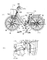
図1に示す電動自転車は、フレーム1と、このフレーム1の下端に装着しているペダル11を取り付けたペダルクランク2と、このペダルクランク2で回転される第1スプロケット4と、チェーン6を介してペダルクランク2で回転される後輪3Bとを備える。このような人力駆動機構により、ペダル11からの人力駆動力を後輪3Bに伝達することができる。
【0011】
また、フロントフォーク7の下端に装着している前輪3Aと、この前輪3Aのフロントハブ8に内蔵されて前輪3Aを駆動するモーター9と、このモーター9に電力を供給する電池10とを備える。このような電動駆動機構により、モーター9を駆動源として前輪3Aを駆動している。そして、フレーム1の下端においては、後述する制御回路15を内蔵するコントロールボックス42が設置されている。
【0012】
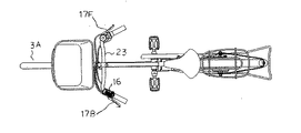
また、図2に示すように、ハンドル23には、通常の自転車と同様に、後ブレーキレバー17Bが乗車した人において左側に取りつけられ、前ブレーキレバー17Fが乗車した人において右側に取り付けられている。そして、前輪3Aを制動するブレーキ機構として、フロントフォーク7には、前輪3Aのリムに、ブレーキシューを押し当てて制動するサイドブレーキ17Xが設置されており、前ブレーキレバー17Fを握り締める操作により、インナーワイヤーを引っ張り、ブレーキ17Xを作動させる。一方、後輪3Bを制動するブレーキ機構として、後輪3Bの中心にドラム形ブレーキ17Yを利用している。
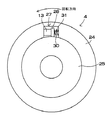
【0013】
ドラム形ブレーキ17Yは、周知の構造であって、図3の要部断面図に示すように、フレーム1に固定される固定軸Fの回りに、後輪3Bと共に回転自在に設置されたリング状部71Aを有する円板状ブレーキドラム71を備える。そして、ブレーキドラム71の内側には、後ブレーキレバー17Bの操作によって外方向、即ちブレーキドラム71のリング状部71Aの内周に摺接してブレーキドラム71の回転(即ち、後輪3Bの回転)を制動するブレーキシュー72が設置されている。ドラム形ブレーキ17Yの外側は、ブレーキ保持部73が覆っている。また、ブレーキ保持部73は、強固に固定するためのアーム部73Aを前方向に延出している(図1参照)。そして、このアーム部73Aに隣接して、後ブレーキワイヤー57のアウターチューブ57bを固定する固定部73Bを有し、インナーワイヤー57aは、連結部材74に固定され、連結部材74はブレーキシュー72を操作する延出バー(図示せず)に連結されている。なお、図1(b)に示すように、固定部73Bには、周知のように、後ブレーキワイヤー57の長さを調整する調整ネジA、ナットBが設けられている。このような構造により、後ブレーキレバー17Bを握り締める操作により、後ブレーキワイヤー57のインナーワイヤー57aを引っ張り、連結部材74が変位して、延出バーを動かしブレーキシュー72を働かせて、後輪3Bを制動する。
【0014】
この電動自転車は、ペダル11を踏むと、ペダルクランク2が第1スプロケット4を回転し、第1スプロケット4がチェーン6と第2スプロケット5を介して後輪3Bを回転する。ペダルクランク2で後輪3Bを駆動するとき、人力によるトルクを検出してフロントハブ8に内蔵されるモーター9に電池10から電力が供給され、補助的にモーター9が前輪3Aを駆動する。電動自転車は、設定速度よりも遅い領域において、モーター9が前輪3Aを駆動する回転トルクと、ペダルクランク2が後輪3Bを駆動する回転トルクとが同じになるようにモーター9への供給電力を制御している。自転車が設定速度になるとモーター9は車輪3を駆動しなくなる。前輪3Aをモーター9で駆動する電動自転車は、前輪3Aに鍵12を設けている。この鍵12はロック状態で前輪3Aが回転されるのを確実に停止する。したがって、鍵12をロックする状態で、誤動作等でモーター9が前輪3Aを駆動しても、前輪3Aが回転することがない。更には、本実施例においては、後輪3Bを施錠できる後輪用の鍵12Bも設けている。
【0015】
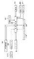
図4は、図1の電動自転車に搭載されて、電池10がモーター9に電力を供給する回路のブロック図である。このブロック図に示す電動自転車は、ペダル11の踏力が車輪3を駆動するトルクを検出するクランクトルクセンサ13と、車輪3を駆動するモーター9と、このモーター9に電力を供給する電池10と、電池10とモーター9との間に接続されて、電池10からモーター9に供給する電力を制御する制御回路15とを備える。
【0016】
さらに、このブロック図の電動自転車は、自転車の走行状態を切り換える手元操作部16と、自転車のブレーキレバー17が操作されたことを検出して回生制動のタイミングを特定する、後ブレーキレバー17Bの操作に連動した回生スイッチ18と、制御回路15に使用される回路部品等の温度を検出する温度センサ19と、電池10の電流と電圧を検出する電流センサ20および電圧センサ21を制御回路15に連結している。
【0017】
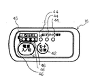
ハンドル23に装着された手元操作部16の機能、表示について、図5を用いて、説明する。図において、左側に位置する円形の第1操作ボタン41は、電源のON、OFFを行うスイッチであり、非押圧時には突出し、押圧時にはへこむようになっている。電源がONのときは、人力でペダルを踏んで所定以上の負荷がかかるとき、補助的に、モーター9にて回転力は発生させて、前輪3Aを回転させ、自転車を推進させる。電源がOFFのときは、このような回転力を発っせず、通常の自転車と同様に乗車する。
【0018】
略中央に位置する円形の第2操作ボタン42は、モーター9の補助的な回転力の度合い(モード)を設定するものであり、詳しくは、この度合いを、小、オート、大に切り替えるものであり、非押圧時には突出し、押圧時にはへこむようになっている。第2操作ボタン42の押圧操作により、モード表示部43に配置された3つの透明の円形表示窓44の内、対応した一つを点灯させる。各円形表示窓44下には、赤色発光のLEDが配置されている。モードについては、表示窓44の左側より順に、省エネ(回転力度合い小)、オート(人からの踏力トルクが小さいとき、アシスト率が小さく、人からの踏力トルクが大きいとき、アシスト率が大きい)、標準(回転力度合い大)に対応している。
【0019】
また、上側に位置する電池残量・回生充電表示部45は、電池10の残量を表示し、また、回生充電状態を表示するものである。後ブレーキレバー17Bを操作せず、回生スイッチ18がオフのときは、表示部45は電池10の残量を表示し、制御回路15より、電池の電圧検出、使用電力量の積算等により、電池の残量を表示する。このため、表示部45において、3つの透明で円形の表示窓46が設けられて、残量に対応した一つの残量表示窓46を点灯させる。なお、各残量表示窓46の下には、赤色LEDが配置され、LEDの点灯により、残量表示窓46が点灯される。
【0020】
また、後ブレーキレバー17Bを握って、回生充電する状態においては、これら表示窓46、46、46において、左から右に順次、各表示窓46が点灯して消灯する状態を、走らすことにより、乗車する人が回生制動され、回生充電する状態を、目で見て把握することができる。
【0021】
また、制御回路15は、回路部品の温度が設定温度よりも高くなる過熱異常信号が温度センサ19から入力されると、電池10からの電流を遮断して回路を保護する。さらに、制御回路15は、電流センサ20と電圧センサ21の入力信号でモーター9に供給する電流を制御すると共に、電池10の残容量を演算して電池10が過放電にならないように放電電流を制御する。浸水センサ22の役割を以下に説明する。詳細な説明は省略するが、後述するように、回転するクランクトルクセンサ13からの電気出力を制御回路15に伝達するために、スリップリングを採用しているが、このスリップリングが水にぬれた時に正常に電気出力を伝達することができない。このために、水ぬれを浸水センサ22にて検出して、水ぬれが検出されたときは、踏力に基づいてモーター9を正常に駆動することができないので、モーター9の駆動を停止する。
【0022】
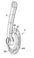
クランクトルクセンサ13は、ペダルクランク2で回転される第1スプロケット4に内蔵している。図6は、クランクトルクセンサ13を内蔵する第1スプロケット4の概略図を示している。この第1スプロケット4の斜視図を図7と図8に示す。これ等の図に示す第1スプロケット4は、外周にチェーン6をかける歯(図示せず)を別途設けている外輪24と、この外輪24の内側にあってペダルクランク2で回転される内輪25とを備える。内輪25は外輪24に対して所定の角度は回転できるように連結される。図9の断面図に示すように、内輪25は外周縁に外輪24を回転できるように案内する外周溝26を設けている。この外周溝26に、外輪24の内周縁を、回転できるが軸方向に抜けることがないように案内している。外輪24はクランクトルクセンサ13を配設するための凹部27を内周部に設けている。内輪25は、外輪24の凹部27に突出する駆動アーム28を有し、この駆動アーム28と凹部27との間にクランクトルクセンサ13を配設している。内輪25は、図7と図8に示すように、クランクトルクセンサ13を内蔵する筒部29を備えており、この筒部29の内側にクランクトルクセンサ13を配設している。さらに、駆動アーム28は、クランクトルクセンサ13に当接する反対側に押しバネであるコイルスプリング30を配設している。コイルスプリング30は、駆動アーム28を一定の圧力でクランクトルクセンサ13に押圧している。外輪24は凹部27に突出して、コイルスプリング30に挿通される凸部31を設けている。コイルスプリング30は、外輪24の凸部31に挿入され、内輪25の筒部29に入れられて定位置に配置される。この第1スプロケット4は、ペダルクランク2で内輪25が回転されると、内輪25の駆動アーム28がクランクトルクセンサ13を介して外輪24を回転させる。ペダルクランク2の回転力は、クランクトルクセンサ13を介して外輪24を回転し、外輪24がチェーン6を介して後輪3Bを回転させる。ペダル11に強い踏力が作用すると、内輪25がクランクトルクセンサ13を押圧する圧力も強くなる。したがって、クランクトルクセンサ13は、これに作用する圧力を検出して、ペダルクランク2の回転トルクを検出できる。この図のクランクトルクセンサ13は、磁歪素子を利用した圧力センサであって、クランクトルクセンサ13からの電気出力は、詳細な説明は省略するが、回転するクランクトルクセンサ13からの電気出力を得るためにスリップリングを利用して、制御回路15にて検出される。
【0023】
ただし、本発明はクランクトルクセンサ13を圧力センサに特定しない。クランクトルクセンサ13には変位センサも使用できる。図10は変位センサをクランクトルクセンサ13に使用する具体例を示す。この図の第1スプロケット4は、内輪25の駆動アーム28に凸部28Aを設けており、この凸部28Aの移動を変位センサで検出する。内輪25の駆動アーム28と外輪24の凹部27との間には押しバネであるコイルスプリング32を配設している。コイルスプリング32は、内輪25がペダルクランク2の強い踏力で駆動されるほど圧縮されて短くなる。コイルスプリング32が圧縮されると、内輪25の駆動アーム28の凸部28Aが変位センサに接近し、あるいは変位センサに押し込まれる。凸部28Aの移動した位置が変位センサで検出されて、ペダルクランク2のトルクが検出される。
【0024】
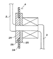
次に、本発明の特徴点である回生制動のスイッチング機構について、説明する。 回生スイッチ18は、後ブレーキレバー17Bが操作されたことを検出するスイッチで、ブレーキレバー17で引っ張られる後ブレーキワイヤー57の途中に設けられる(図1参照)。なお、回生スイッチ18は、後ブレーキレバー17B内に設けることもできる。
【0025】
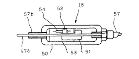
ブレーキワイヤー57の途中に設置される例を、図11、図12を用いて説明する。回生スイッチ18は、図示するように、後ブレーキワイヤー57の長さ途中に取り付けられた箱状のスイッチケース50と、スイッチケース50内で後ブレーキワイヤー67のインナーワイヤ57aに取り付けられたスリーブ51と、スリーブ51の上面に取り付けられたマグネット52と、マグネット52に対向するように、スイッチケース内の回路基板53(電気配線は図示せず)に取り付けられたリードスイッチ54とを備えている。なお、57bは後ブレーキワイヤー57のアウターチユーブである。
【0026】
リードスイッチ54は、マグネット52が図11の状態(後ブレーキレバー17Bを操作しない状態)にあるとき、OFFであり、この状態から、図12に示すように、インナーワイヤ57aの動きにより左方向へ移動するとONになる。なお、図示しないが、スイッチケース50は、略箱形状で密閉構造となっている。
【0027】
このようなスイッチング機構における自転車運転時の動作を、以下に説明する。ペダル11をこいで自転車を運転するときには、トルクセンサ13が人力を検出して、モーター9が前輪3Aを補助的に駆動する。このとき、回生スイッチ18におけるリードスイッチ54とマグネット52とは、図11に示す状態にある。
【0028】
この状態から、後ブレーキレバー17Bを握ることによりブレーキ操作を行うと、後ブレーキワイヤー57のインナーワイヤー57aが引かれる。インナーワイヤー57aによりマグネット52が左へ移動し、図12の状態になると共にブレーキシュー72がブレーキドラム71に摺接して後輪3Bを制動する。
【0029】
そして、このようにブレーキが操作されて、回生スイッチ18がON状態となったとき、ON信号を制御回路15に出力する。制御回路15は、ブレーキが操作された信号が入力されると、モーター9を発電機として使用して、前輪3Aを回生制動して電池10を充電する。制御回路15は、モーター9の界磁コイルに流す電流のタイミングを制御して、モーター9を発電機として電池10を充電する。制御回路15は、電池10の残容量を検出し、電池10の過充電を防止しながら回生制動して電池10を充電する。すなわち、電池10が満充電になると、ブレーキが操作されても回生を停止して電池10の充電を停止する。
【0030】
ブレーキを操作したことを検出して回生制動する電動自転車は、スムーズに制動できると共に、運動のエネルギーを有効に回収して電池10を充電できる。このため、自転車を速やかに停止できると共に、電池10による走行距離を長くできる特長がある。
【0031】
そして、本実施例においては、後ブレーキレバー17Bを握るとき、少し握る(=後ブレーキレバー17Bを少し変位させる、即ち、浅く握る)と、リードスイッチ54がオンして回生スイッチ18がオン状態となり、回生制動する状態(第1制動状態)となる。更に、後ブレーキレバー17Bを深く握るなら、回生制動の状態が維持されるとともに、インナーワイヤー17aを引っ張り、連結部材74が変位して、延出バーを動かしブレーキシュー72を働かせて、後輪3Bを制動する(第2制動状態)になるように、ブレーキワイヤー57を調整してある。
なお、必要に応じて、回生制動と、ブレーキシュー72を働かせるブレーキ機構による制動を、同時に働かせように、ブレーキワイヤー57を調整することも可能である。
【0032】
また、図11、12に示したように、この電気自転車においては、回生スイッチ18としてリードスイッチ54を用いたが、これに代えて、スイッチOFF状態を示す図13及びスイッチON状態を示す図14のように、リミットスイッチ60を用いてもよい。なお、両図において61は、後ブレーキワイヤー57のインナーワイヤ57aに取り付けられた作動片である。
【0033】
以上の実施例においては、自転車の走行中に、後輪3Bの制動のために、後ブレーキレバー17Bを徐々に握るなら、まず、回生スイッチ18が図11に示す状態より、図12に示す状態に移行して、回生スイッチ18がオン状態となることより、モーター9が発電機として利用されて、前輪3Aが回生制動される第1制動状態となる。この後ブレーキレバー17Bの握り状態を維持するなら、モーター9が低速となるまで、回生制動状態を維持できることになる。この第1制動状態である回生制動の状態においては、乗車する人が制動する感触を乗車して体感できると共に、手元操作部16においては、上述のように表示窓46、46、46において左から右に順次、各表示窓46が点灯して消灯する状態が走るので、回生制動され、回生充電する状態を、目で見て把握することができる。
【0034】
この状態より、更に、後ブレーキレバー17Bを深く握るなら、継続して回生スイッチ18がオン状態が維持され回生制動されると共に、インナーワイヤー17aを引っ張り、連結部材74が変位して、延出バーを動かしブレーキシュー72を働かせて、後輪3Bを制動する第2制動状態となる。
【0035】
【発明の効果】
本発明の電動自転車においては、後輪へのブレーキ操作時において、後輪が制動されると共に、前輪のモーターを発電機として利用して、前輪が回生制動されることにより、後輪へのブレーキ操作により、後輪及び前輪の両輪を一度に制動することができる。よって、上述の従来例では、後輪に回生制動とブレーキ機構による制動が急激にかかっていたが、本発明には、両輪を制動することになるので、安定して停止することができる。
【0036】
また、本発明の電動自転車においては、ブレーキレバーの操作時には、モーターを発電機として利用して車輪が回生制動される第1制動状態と、このように回生制動されると共に、ブレーキ機構により制動される第2制動状態とを備える。上述の従来例では、ブレーキ機構による制動と回生制動による制動が同時にかけられていので、ブレーキ機構による制動により速やかに低速となるので、十分に長時間に回生充電することができなかったが、本発明においては、回生制動される第1制動状態のみを維持することが可能であるので、走行中の電動自転車の運動エネルギーを、ブレーキ機構による制動で消費することなく、回生制動に利用することができる。そして、回生制動により、電池を充電することができる。モーターを駆動源とする電動駆動機構は、前輪に限らず、後輪を駆動してもよい。
【図面の簡単な説明】
【図1】本発明の一実施例にかかる電動自転車の側面図であって、(a)は全体の側面図、(b)は後輪部分の拡大側面図(スタンドは立てた状態)である。
【図2】本発明の一実施例にかかる電動自転車の上面図である。
【図3】本発明の一実施例におけるドラム型ブレーキの要部断面図である。
【図4】図1に示す電動自転車のモーターを駆動する回路のブロック図である。
【図5】本発明の一実施例における手元操作部の上面図である。
【図6】図1に示す電動自転車の第1スプロケットを示す概略図である。
【図7】第1スプロケットの斜視図である。
【図8】図7に示す第1スプロケットの背面斜視図である。
【図9】第1スプロケットの概略断面図である。
【図10】クランクトルクセンサの他の一例を示す概略図である。
【図11】回生スイッチのスイッチケースの断面図であって、オフ状態を示す。
【図12】回生スイッチのスイッチケースの断面図であって、オン状態を示す。
【図13】他の回生スイッチのスイッチケースの断面図であって、オフ状態を示す。
【図14】他の回生スイッチのスイッチケースの断面図であって、オン状態を示す。
【符号の説明】
1…フレーム
2…ペダルクランク
3…車輪 3A…前輪 3B…後輪
4…第1スプロケット
5…第2スプロケット
6…チェーン
7…フロントフォーク
8…フロントハブ
9…モーター
10…電池
11…ペダル
12…鍵
13…クランクトルクセンサ
14…回転センサ
15…制御回路
16…手元操作部
17…ブレーキレバー
18…回生スイッチ
19…温度センサ
20…電流センサ
21…電圧センサ
22…浸水センサ
23…ハンドル
24…外輪
25…内輪
26…外周溝
27…凹部
28…駆動アーム 28A…凸部
29…筒部
30…コイルスプリング
31…凸部
32…コイルスプリング[0001]
TECHNICAL FIELD OF THE INVENTION
The present invention relates to an electric bicycle.
[0002]
[Prior art]
The electric bicycle includes an electric drive mechanism using a motor as a drive source to drive the rear wheels, and has a power supply unit such as a storage battery to supply electric power to the motor.
[0003]
Japanese Patent Application Laid-Open No. 2001-30974 discloses that when a brake is applied during traveling on a downhill or the like, power generated by motor rotation is collected in a power supply unit and the power supply unit is charged. I have.
[0004]
[Patent Document 1]
JP-A-2001-30974 [0005]
[Problems to be solved by the invention]
In the above-described conventional example, the brake operation causes the braking by the brake mechanism and the braking by the regenerative braking at the same time, and the braking is suddenly applied.
[0006]
Also, when the brake operation of the rear wheel is performed, braking by the brake mechanism and braking by regenerative braking are applied to the rear wheel, and the rear wheel is suddenly braked.
[0007]
The present invention has been made to solve such a problem, and an object of the present invention is to prevent sudden braking when regenerative braking is applied by operating a brake.
[0008]
[Means for Solving the Problems]
The electric bicycle according to the present invention is an electric bicycle including a human-powered driving mechanism that transmits a human-powered driving force from a pedal to a rear wheel, and an electric-powered driving mechanism that uses a motor that drives a front wheel as a driving source. When the brake is operated, the rear wheel is braked and the motor of the front wheel is used as a generator to regeneratively brake the front wheel.
[0009]
An electric bicycle including a human-powered driving mechanism that transmits a human-powered driving force from a pedal to a rear wheel, and an electric-powered driving mechanism that uses a motor that drives the wheels as a drive source. It is characterized by comprising a first braking state in which the wheels are regeneratively braked as a generator, and a second braking state in which the wheels are regeneratively braked and braked by a brake mechanism.
[0010]
BEST MODE FOR CARRYING OUT THE INVENTION
The electric bicycle shown in FIG. 1 includes a frame 1, a
[0011]
The vehicle also includes a front wheel 3A mounted on the lower end of the front fork 7, a
[0012]
As shown in FIG. 2, the
[0013]
The drum-
[0014]
In this electric bicycle, when the
[0015]
FIG. 4 is a block diagram of a circuit mounted on the electric bicycle of FIG. The electric bicycle shown in this block diagram includes a
[0016]
Further, the electric bicycle shown in this block diagram has a
[0017]
The function and display of the
[0018]
The circular
[0019]
Further, the battery remaining amount / regenerative
[0020]
Further, in a state in which the
[0021]
Further, when an overheat abnormality signal in which the temperature of the circuit component becomes higher than the set temperature is input from the
[0022]
The
[0023]
However, the present invention does not specify the
[0024]
Next, a regenerative braking switching mechanism which is a feature of the present invention will be described. The
[0025]
An example of being installed in the middle of the
[0026]
The
[0027]
The operation of such a switching mechanism during bicycle driving will be described below. When driving the bicycle by pedaling, the
[0028]
When the brake operation is performed by gripping the
[0029]
When the
[0030]
The electric bicycle that performs the regenerative braking by detecting that the brake has been operated can smoothly brake, and also can effectively collect the energy of the movement and charge the battery 10. For this reason, there is a feature that the bicycle can be stopped quickly and the running distance by the battery 10 can be lengthened.
[0031]
Then, in the present embodiment, when the
If necessary, the
[0032]
Also, as shown in FIGS. 11 and 12, in this electric bicycle, the
[0033]
In the above embodiment, if the
[0034]
In this state, if the
[0035]
【The invention's effect】
In the electric bicycle of the present invention, when the rear wheel is braked, the rear wheel is braked, and the front wheel is regeneratively braked by using the motor of the front wheel as a generator, thereby braking the rear wheel. By operation, both the rear wheel and the front wheel can be braked at once. Therefore, in the above-described conventional example, the regenerative braking and the braking by the brake mechanism are suddenly applied to the rear wheels. However, according to the present invention, since both wheels are braked, the vehicle can be stopped stably.
[0036]
Further, in the electric bicycle of the present invention, when the brake lever is operated, the motor is used as a generator to regeneratively brake the wheels, and the vehicle is regeneratively braked and braked by the brake mechanism. A second braking state. In the above-described conventional example, since the braking by the brake mechanism and the braking by the regenerative braking are applied at the same time, the speed is quickly reduced by the braking by the brake mechanism, so that the regenerative charging cannot be performed for a sufficiently long time. In the present invention, since only the first braking state in which regenerative braking is performed can be maintained, the kinetic energy of the running electric bicycle can be used for regenerative braking without being consumed by braking by the brake mechanism. it can. Then, the battery can be charged by regenerative braking. The electric drive mechanism using a motor as a drive source is not limited to the front wheels, and may drive rear wheels.
[Brief description of the drawings]
1A and 1B are side views of an electric bicycle according to an embodiment of the present invention, wherein FIG. 1A is an overall side view, and FIG. 1B is an enlarged side view of a rear wheel portion (stand upright). .
FIG. 2 is a top view of the electric bicycle according to one embodiment of the present invention.
FIG. 3 is a sectional view of a main part of a drum type brake according to one embodiment of the present invention.
FIG. 4 is a block diagram of a circuit for driving a motor of the electric bicycle shown in FIG.
FIG. 5 is a top view of a hand operation unit according to the embodiment of the present invention.
FIG. 6 is a schematic view showing a first sprocket of the electric bicycle shown in FIG.
FIG. 7 is a perspective view of a first sprocket.
FIG. 8 is a rear perspective view of the first sprocket shown in FIG. 7;
FIG. 9 is a schematic sectional view of a first sprocket.
FIG. 10 is a schematic diagram showing another example of the crank torque sensor.
FIG. 11 is a sectional view of a switch case of the regenerative switch, showing an off state.
FIG. 12 is a cross-sectional view of a switch case of the regenerative switch, showing an ON state.
FIG. 13 is a sectional view of a switch case of another regenerative switch, showing an off state.
FIG. 14 is a cross-sectional view of a switch case of another regenerative switch, showing an ON state.
[Explanation of symbols]
DESCRIPTION OF SYMBOLS 1 ...
Claims (2)
前輪を駆動するモーターを駆動源とする電動駆動機構とを備える電動自転車であって、
前記後輪へのブレーキ操作時には、前記後輪が制動されると共に、前記前輪の前記モーターを発電機として利用して、前記前輪が回生制動されることを特徴とする電動自転車。A manual drive mechanism for transmitting the manual drive force from the pedal to the rear wheel;
An electric bicycle including an electric drive mechanism using a motor that drives the front wheels as a drive source,
An electric bicycle wherein the rear wheel is braked when the brake is applied to the rear wheel, and the front wheel is regeneratively braked using the motor of the front wheel as a generator.
ブレーキレバーの操作時には、前記モーターを発電機として利用して前記車輪が回生制動される第1制動状態と、このように回生制動されると共に、ブレーキ機構により制動される第2制動状態とを、備えることを特徴とする電動自転車。An electric bicycle including a human-powered driving mechanism that transmits a human-powered driving force from a pedal to a rear wheel, and an electric-powered driving mechanism that uses a motor that drives the wheels as a driving source,
At the time of operating the brake lever, a first braking state in which the wheels are regeneratively braked using the motor as a generator, and a second braking state in which the regenerative braking is performed and the braking mechanism is braked, An electric bicycle, comprising:
Priority Applications (9)
| Application Number | Priority Date | Filing Date | Title |
|---|---|---|---|
| JP2002316794A JP2004149001A (en) | 2002-10-30 | 2002-10-30 | Power-assisted bicycle |
| TW092123394A TWI229047B (en) | 2002-10-30 | 2003-08-26 | Electric bicycle |
| CNB2003101013617A CN100453400C (en) | 2002-10-30 | 2003-10-15 | Electric bicycle |
| CNB2004100825994A CN100551770C (en) | 2002-10-30 | 2003-10-15 | Electrical Bicycle |
| CA002446170A CA2446170C (en) | 2002-10-30 | 2003-10-22 | Electrically assisted bicycle |
| DE60310340T DE60310340T2 (en) | 2002-10-30 | 2003-10-29 | Bicycle with electric auxiliary engine |
| EP03024946A EP1415904B1 (en) | 2002-10-30 | 2003-10-29 | Electrically assisted bicycle |
| DE2003024946 DE03024946T1 (en) | 2002-10-30 | 2003-10-29 | Bicycle with electric auxiliary engine |
| US10/695,761 US6874592B2 (en) | 2002-10-30 | 2003-10-30 | Electrically assisted bicycle |
Applications Claiming Priority (1)
| Application Number | Priority Date | Filing Date | Title |
|---|---|---|---|
| JP2002316794A JP2004149001A (en) | 2002-10-30 | 2002-10-30 | Power-assisted bicycle |
Publications (1)
| Publication Number | Publication Date |
|---|---|
| JP2004149001A true JP2004149001A (en) | 2004-05-27 |
Family
ID=32089557
Family Applications (1)
| Application Number | Title | Priority Date | Filing Date |
|---|---|---|---|
| JP2002316794A Pending JP2004149001A (en) | 2002-10-30 | 2002-10-30 | Power-assisted bicycle |
Country Status (7)
| Country | Link |
|---|---|
| US (1) | US6874592B2 (en) |
| EP (1) | EP1415904B1 (en) |
| JP (1) | JP2004149001A (en) |
| CN (2) | CN100551770C (en) |
| CA (1) | CA2446170C (en) |
| DE (2) | DE03024946T1 (en) |
| TW (1) | TWI229047B (en) |
Cited By (15)
| Publication number | Priority date | Publication date | Assignee | Title |
|---|---|---|---|---|
| JP2009220669A (en) * | 2008-03-14 | 2009-10-01 | Sanyo Electric Co Ltd | Electric bicycle |
| JP2010028970A (en) * | 2008-07-18 | 2010-02-04 | Panasonic Corp | Motor bicycle and brake adjustment method therefor |
| JP2010095203A (en) * | 2008-10-20 | 2010-04-30 | Panasonic Corp | Electric bicycle |
| EP2236373A2 (en) | 2009-04-02 | 2010-10-06 | Kabushiki Kaisha Toshiba | Regenerative braking device and vehicle provided with regenerative braking device |
| WO2011043186A1 (en) * | 2009-10-05 | 2011-04-14 | 太陽誘電株式会社 | Regenerative brake device and motor-assisted vehicle provided with the same |
| JP2011126426A (en) * | 2009-12-18 | 2011-06-30 | Panasonic Corp | Electrically power-assisted bicycle and method of adjusting brake of the same |
| JP2011259682A (en) * | 2010-06-11 | 2011-12-22 | Shimano Inc | Bicycle regenerative brake control device |
| WO2012014396A1 (en) | 2010-07-27 | 2012-02-02 | パナソニック株式会社 | Electric bicycle |
| WO2012032731A1 (en) | 2010-09-08 | 2012-03-15 | パナソニック株式会社 | Electric bicycle |
| US8381884B2 (en) | 2008-11-10 | 2013-02-26 | Shimano Inc. | Bicycle braking system |
| JP2013043487A (en) * | 2011-08-22 | 2013-03-04 | Yamaha Motor Co Ltd | Power-assisted bicycle |
| US8730483B2 (en) | 2009-10-05 | 2014-05-20 | Taiyo Yuden Co., Ltd. | Interferometric measurement of displacement in axial direction of a grating |
| JP2015029414A (en) * | 2009-04-02 | 2015-02-12 | 株式会社東芝 | Regenerative brake system and vehicle provided therewith |
| JP2019108105A (en) * | 2017-12-20 | 2019-07-04 | 株式会社シマノ | Drive system |
| JP2019127239A (en) * | 2018-01-26 | 2019-08-01 | 株式会社シマノ | Brake control device, brake device including the same, and brake system |
Families Citing this family (59)
| Publication number | Priority date | Publication date | Assignee | Title |
|---|---|---|---|---|
| US20060151224A1 (en) * | 2003-01-24 | 2006-07-13 | Vasser Paul M | Human powered golf cart with auxiliary power source |
| US6933836B2 (en) * | 2003-11-06 | 2005-08-23 | Richard Hsu | Bike braking warning control |
| DE502006003191D1 (en) * | 2005-05-13 | 2009-04-30 | Spinwood Trading & Consulting | VEHICLE |
| TWI344258B (en) * | 2005-08-19 | 2011-06-21 | Delta Electronics Inc | Motor driving method and device thereof |
| DE102007051559A1 (en) * | 2007-10-29 | 2009-04-30 | Robert Bosch Gmbh | An electrically powered bicycle and method of operating such a bicycle |
| US7661501B1 (en) | 2008-09-16 | 2010-02-16 | Joab Jay Perdue | Vehicle operated by multiple power sources |
| TWM358112U (en) * | 2009-01-21 | 2009-06-01 | Guang-Xiong Liu | Sensing structure of bicycle power assistance system |
| US20100282534A1 (en) * | 2009-05-07 | 2010-11-11 | Wei-Ting Lin | Motorized Bicycle with Electric Generating Function |
| DE102009054756A1 (en) * | 2009-12-16 | 2011-06-22 | Robert Bosch GmbH, 70469 | Electric bicycle |
| TWI404295B (en) * | 2010-02-23 | 2013-08-01 | 見發先進科技股份有限公司 | Elctric bicycle circuit with complex charging function |
| TWI392619B (en) * | 2010-03-10 | 2013-04-11 | Nat Univ Tsing Hua | A human powered and electricity balanced personal vehicle |
| US9434362B2 (en) * | 2010-03-29 | 2016-09-06 | Current Motor Company | System and method to control regenerative braking |
| DE102011001095B4 (en) | 2010-04-11 | 2019-08-14 | Dr. Ing. H.C. F. Porsche Aktiengesellschaft | A bicycle with electric auxiliary drive and method for operating an electric machine of a bicycle as a brake |
| JP5300792B2 (en) * | 2010-06-11 | 2013-09-25 | 株式会社シマノ | Auxiliary power system for bicycles |
| DE102010039850A1 (en) * | 2010-08-27 | 2012-03-01 | Robert Bosch Gmbh | Control device for controlling an electric drive of an electric bicycle and method for supplying electric loads of an electric bicycle |
| JP5106603B2 (en) * | 2010-08-30 | 2012-12-26 | 株式会社シマノ | Bicycle regenerative braking control device |
| JP2012051446A (en) * | 2010-08-31 | 2012-03-15 | Honda Motor Co Ltd | Bicycle with auxiliary power unit |
| CN103038128B (en) * | 2010-09-16 | 2015-08-12 | 松下电器产业株式会社 | Electrical Bicycle |
| JP5479291B2 (en) * | 2010-09-30 | 2014-04-23 | 本田技研工業株式会社 | Control device for battery-assisted bicycle |
| JP5564391B2 (en) * | 2010-09-30 | 2014-07-30 | 本田技研工業株式会社 | Control device for battery-assisted bicycle |
| US20120145469A1 (en) * | 2010-12-14 | 2012-06-14 | Gabriel Yui Lung Tong | Wheeled device with lever pedal mechanism |
| CN103221251B (en) * | 2010-12-28 | 2016-06-22 | 川崎重工业株式会社 | The generation control system of electric vehicle |
| JP2013047079A (en) * | 2011-08-29 | 2013-03-07 | Shimano Inc | Bicycle rear hub |
| US8640796B2 (en) * | 2012-05-11 | 2014-02-04 | Wzi, Inc. | Solar-powered quadricycle with regenerative and dissipative braking |
| JP5689849B2 (en) * | 2012-05-18 | 2015-03-25 | マイクロスペース株式会社 | Motor drive control device |
| KR20140038024A (en) * | 2012-09-19 | 2014-03-28 | 주식회사 만도 | Electric bicycle |
| KR20140038048A (en) * | 2012-09-19 | 2014-03-28 | 주식회사 만도 | Eletric bicycle and control method thereof |
| CN103043172A (en) * | 2012-12-30 | 2013-04-17 | 广东盈科电子有限公司 | Traveling control system of electric vehicle |
| DE102013216723A1 (en) * | 2013-08-22 | 2015-02-26 | Robert Bosch Gmbh | Muscle and / or engine power operable vehicle and method of operating the vehicle |
| DE102014204853A1 (en) * | 2014-03-17 | 2015-09-17 | Robert Bosch Gmbh | Electric bicycle with recuperation option |
| US9771124B2 (en) * | 2015-02-25 | 2017-09-26 | Ford Global Technologies, Llc | Wheel rim-mounted regeneration coil-magnet system |
| US9764796B2 (en) * | 2015-03-19 | 2017-09-19 | GM Global Technology Operations LLC | Electric bike optical shift detection and control |
| US9925999B2 (en) | 2015-09-29 | 2018-03-27 | Radio Flyer Inc. | Power assist wagon |
| JP2017077126A (en) | 2015-10-16 | 2017-04-20 | ヤマハ発動機株式会社 | Electric propulsion machine and battery unit |
| JP2017112801A (en) * | 2015-12-18 | 2017-06-22 | ローベルト ボッシュ ゲゼルシャフト ミット ベシュレンクテル ハフツング | Fluid pressure type brake system, bicycle, and control method of fluid pressure type brake system |
| EP3427998A4 (en) * | 2016-03-11 | 2019-10-16 | Taiyo Yuden Co., Ltd. | Drive device for electrically assisted vehicle, electrically assisted vehicle, and electricity storage device |
| US11161565B2 (en) * | 2016-08-05 | 2021-11-02 | Shimano Inc. | Bicycle control device and bicycle electric assist unit including bicycle control device |
| EP3308993A1 (en) * | 2016-09-30 | 2018-04-18 | Taiyo Yuden Co., Ltd. | Motor driving control apparatus and electrically assisted vehicle |
| US10583852B2 (en) | 2016-11-02 | 2020-03-10 | Radio Flyer Inc. | Foldable wagon |
| US10773769B2 (en) * | 2017-04-03 | 2020-09-15 | Shimano Inc. | Bicycle drive system, bicycle drive unit, and bicycle battery unit |
| JP2019039291A (en) * | 2017-08-23 | 2019-03-14 | パナソニックIpマネジメント株式会社 | Locking system and unlocking method for motor-driven bicycle |
| US20190100275A1 (en) * | 2017-10-03 | 2019-04-04 | PalTorc, Inc. | Smart crank control for e-bike |
| US10479445B2 (en) | 2017-10-03 | 2019-11-19 | PalTorc, Inc. | Smart crank control for E-bike |
| USD898254S1 (en) | 2017-10-25 | 2020-10-06 | North Carolina State University | Combined lock and light signaling system for multi-wheeled vehicles |
| USD866676S1 (en) | 2017-11-02 | 2019-11-12 | Radio Flyer Inc. | Foldable wagon |
| TWI677667B (en) * | 2018-09-27 | 2019-11-21 | 光旴科技股份有限公司 | Crank with direct force measuring device |
| US11286017B2 (en) * | 2018-12-27 | 2022-03-29 | Msns, Llc | Adjustable brake lever sensor system |
| US11459061B2 (en) * | 2019-01-12 | 2022-10-04 | Sram, Llc | Bicycle component motion control |
| DE102020102993A1 (en) * | 2019-03-19 | 2020-09-24 | Schaeffler Technologies AG & Co. KG | System for propelling and braking a vehicle |
| CN111391954A (en) * | 2019-12-16 | 2020-07-10 | 吴国栋 | Combined type lover electric bicycle capable of realizing four-person resultant force and self-charging |
| CN112550546B (en) * | 2020-11-23 | 2022-04-15 | 江苏科技大学 | Electric vehicle power-assisted operation control system and control method thereof |
| CN113022763B (en) * | 2021-04-30 | 2022-03-15 | 浙江阿波罗运动科技股份有限公司 | Cross-country motorcycle |
| CN113428283B (en) * | 2021-06-01 | 2023-03-21 | 重庆大学 | Hydraulic power-assisted bicycle suitable for multi-speed-change area |
| US11407298B1 (en) | 2021-11-15 | 2022-08-09 | Amos Power, Inc. | Removable battery unit for an electric vehicle |
| US11364959B1 (en) | 2021-12-27 | 2022-06-21 | Amos Power, Inc. | Modular robotic vehicle |
| USD1014573S1 (en) | 2022-04-01 | 2024-02-13 | Amos Power, Inc. | Removable track unit for a robotic vehicle |
| USD1014569S1 (en) | 2022-04-01 | 2024-02-13 | Amos Power, Inc. | Robotic vehicle |
| US11547035B1 (en) | 2022-05-24 | 2023-01-10 | Amos Power, Inc. | Lift assist for an electrically driven hitch on an robotic vehicle |
| CN115009402A (en) * | 2022-07-15 | 2022-09-06 | 中山博力高电子有限公司 | Bicycle blind area monitoring system |
Citations (6)
| Publication number | Priority date | Publication date | Assignee | Title |
|---|---|---|---|---|
| JPH09207867A (en) * | 1996-02-02 | 1997-08-12 | Shimano Inc | Braking method of bicycle with power and its controller |
| JPH09254861A (en) * | 1996-03-26 | 1997-09-30 | Yazaki Corp | Electric power-assisted bicycle |
| JPH1035576A (en) * | 1996-05-24 | 1998-02-10 | Sony Corp | Travelling device and travel control method |
| JPH11150811A (en) * | 1997-11-14 | 1999-06-02 | Yamaha Motor Co Ltd | Motor drive and control device and compact motorized mobile object mounted with the motor drive control device |
| JPH11227668A (en) * | 1998-02-13 | 1999-08-24 | Aichi Steel Works Ltd | Torque assist bicycle and its manufacture |
| JP2000118477A (en) * | 1998-10-12 | 2000-04-25 | Sony Corp | Bicycle with assistance function |
Family Cites Families (15)
| Publication number | Priority date | Publication date | Assignee | Title |
|---|---|---|---|---|
| US3841428A (en) * | 1971-12-20 | 1974-10-15 | N Bialek | Auxiliary electric drive attachment for a vehicle |
| US3921745A (en) * | 1973-07-23 | 1975-11-25 | Mcculloch Corp | Electric bicycle |
| US3921741A (en) * | 1974-07-11 | 1975-11-25 | Avco Corp | Bicycle with electric motor assist |
| US4221275A (en) * | 1978-04-28 | 1980-09-09 | Pennebaker William B | Motor-assist vehicle |
| IL71233A (en) * | 1984-03-14 | 1986-11-30 | Iliya Goldenfeld | Auxiliary drive for pedal-driven road vehicles |
| US5237263A (en) * | 1991-06-17 | 1993-08-17 | Gannon Henry M | Electric and pedal driven bicycle with solar charging |
| JPH08140212A (en) * | 1994-11-09 | 1996-05-31 | Yamaha Motor Co Ltd | Regenerative controller |
| US5777442A (en) * | 1996-01-29 | 1998-07-07 | Yamaha Hatsudoki Kabushiki Kaisha | Control for electric power assisted vehicle |
| JPH1059266A (en) * | 1996-08-20 | 1998-03-03 | Sanyo Electric Co Ltd | Battery residual amount display method of assisted-motor bicycle |
| US6155369A (en) * | 1998-03-26 | 2000-12-05 | Whittaker; Ronald W. | Electric bicycle |
| JP2001030974A (en) * | 1999-07-21 | 2001-02-06 | Daido Steel Co Ltd | Power-assisted bicycle |
| JP4390935B2 (en) * | 1999-10-25 | 2009-12-24 | ヤマハ発動機株式会社 | Battery status display device for electric vehicle |
| JP2001199378A (en) * | 2000-01-19 | 2001-07-24 | Honda Motor Co Ltd | Motor-assisted bicycle |
| US6446745B1 (en) * | 2000-06-30 | 2002-09-10 | Michael John Lee | Control system for electric powered vehicle |
| US6342769B1 (en) * | 2000-11-07 | 2002-01-29 | Orville J. Birkestrand | Electronic throttle/brake control system for monitorized wheel hub |
-
2002
- 2002-10-30 JP JP2002316794A patent/JP2004149001A/en active Pending
-
2003
- 2003-08-26 TW TW092123394A patent/TWI229047B/en not_active IP Right Cessation
- 2003-10-15 CN CNB2004100825994A patent/CN100551770C/en not_active Expired - Fee Related
- 2003-10-15 CN CNB2003101013617A patent/CN100453400C/en not_active Expired - Fee Related
- 2003-10-22 CA CA002446170A patent/CA2446170C/en not_active Expired - Fee Related
- 2003-10-29 EP EP03024946A patent/EP1415904B1/en not_active Expired - Fee Related
- 2003-10-29 DE DE2003024946 patent/DE03024946T1/en active Pending
- 2003-10-29 DE DE60310340T patent/DE60310340T2/en not_active Expired - Lifetime
- 2003-10-30 US US10/695,761 patent/US6874592B2/en not_active Expired - Fee Related
Patent Citations (6)
| Publication number | Priority date | Publication date | Assignee | Title |
|---|---|---|---|---|
| JPH09207867A (en) * | 1996-02-02 | 1997-08-12 | Shimano Inc | Braking method of bicycle with power and its controller |
| JPH09254861A (en) * | 1996-03-26 | 1997-09-30 | Yazaki Corp | Electric power-assisted bicycle |
| JPH1035576A (en) * | 1996-05-24 | 1998-02-10 | Sony Corp | Travelling device and travel control method |
| JPH11150811A (en) * | 1997-11-14 | 1999-06-02 | Yamaha Motor Co Ltd | Motor drive and control device and compact motorized mobile object mounted with the motor drive control device |
| JPH11227668A (en) * | 1998-02-13 | 1999-08-24 | Aichi Steel Works Ltd | Torque assist bicycle and its manufacture |
| JP2000118477A (en) * | 1998-10-12 | 2000-04-25 | Sony Corp | Bicycle with assistance function |
Cited By (19)
| Publication number | Priority date | Publication date | Assignee | Title |
|---|---|---|---|---|
| JP2009220669A (en) * | 2008-03-14 | 2009-10-01 | Sanyo Electric Co Ltd | Electric bicycle |
| JP2010028970A (en) * | 2008-07-18 | 2010-02-04 | Panasonic Corp | Motor bicycle and brake adjustment method therefor |
| JP2010095203A (en) * | 2008-10-20 | 2010-04-30 | Panasonic Corp | Electric bicycle |
| US8381884B2 (en) | 2008-11-10 | 2013-02-26 | Shimano Inc. | Bicycle braking system |
| EP2236373A2 (en) | 2009-04-02 | 2010-10-06 | Kabushiki Kaisha Toshiba | Regenerative braking device and vehicle provided with regenerative braking device |
| JP2010259312A (en) * | 2009-04-02 | 2010-11-11 | Toshiba Corp | Regenerative braking device and vehicle equipped with regenerative braking device |
| JP2015029414A (en) * | 2009-04-02 | 2015-02-12 | 株式会社東芝 | Regenerative brake system and vehicle provided therewith |
| US8730483B2 (en) | 2009-10-05 | 2014-05-20 | Taiyo Yuden Co., Ltd. | Interferometric measurement of displacement in axial direction of a grating |
| WO2011043186A1 (en) * | 2009-10-05 | 2011-04-14 | 太陽誘電株式会社 | Regenerative brake device and motor-assisted vehicle provided with the same |
| JP2011083081A (en) * | 2009-10-05 | 2011-04-21 | Taiyo Yuden Co Ltd | Regenerative brake device and motor-assisted vehicle provided with the same |
| US9573569B2 (en) | 2009-10-05 | 2017-02-21 | Taiyo Yuden Co., Ltd. | Regenerative brake device and motor-assisted vehicle provided with the same |
| JP2011126426A (en) * | 2009-12-18 | 2011-06-30 | Panasonic Corp | Electrically power-assisted bicycle and method of adjusting brake of the same |
| JP2011259682A (en) * | 2010-06-11 | 2011-12-22 | Shimano Inc | Bicycle regenerative brake control device |
| WO2012014396A1 (en) | 2010-07-27 | 2012-02-02 | パナソニック株式会社 | Electric bicycle |
| WO2012032731A1 (en) | 2010-09-08 | 2012-03-15 | パナソニック株式会社 | Electric bicycle |
| JP2013043487A (en) * | 2011-08-22 | 2013-03-04 | Yamaha Motor Co Ltd | Power-assisted bicycle |
| JP2019108105A (en) * | 2017-12-20 | 2019-07-04 | 株式会社シマノ | Drive system |
| JP2019127239A (en) * | 2018-01-26 | 2019-08-01 | 株式会社シマノ | Brake control device, brake device including the same, and brake system |
| US11345433B2 (en) | 2018-01-26 | 2022-05-31 | Shimano Inc. | Brake control device, braking device including brake control device, and brake system |
Also Published As
| Publication number | Publication date |
|---|---|
| US6874592B2 (en) | 2005-04-05 |
| TW200406336A (en) | 2004-05-01 |
| CN1498816A (en) | 2004-05-26 |
| DE60310340D1 (en) | 2007-01-25 |
| DE60310340T2 (en) | 2007-03-29 |
| CN100551770C (en) | 2009-10-21 |
| DE03024946T1 (en) | 2005-01-13 |
| TWI229047B (en) | 2005-03-11 |
| US20040084238A1 (en) | 2004-05-06 |
| CA2446170C (en) | 2006-10-03 |
| EP1415904A3 (en) | 2005-04-20 |
| CA2446170A1 (en) | 2004-04-30 |
| CN100453400C (en) | 2009-01-21 |
| EP1415904A2 (en) | 2004-05-06 |
| EP1415904B1 (en) | 2006-12-13 |
| CN1607154A (en) | 2005-04-20 |
Similar Documents
| Publication | Publication Date | Title |
|---|---|---|
| JP2004149001A (en) | Power-assisted bicycle | |
| US9550489B2 (en) | Device and method for regulating an energy recovery in a pedal-driven vehicle | |
| JP4118984B2 (en) | Electric assist bicycle | |
| EP2617636B1 (en) | Electric bicycle | |
| EP1886913B1 (en) | Electrically assisted bicycle | |
| EP0517224B1 (en) | Muscle-operated vehicle | |
| JP5634273B2 (en) | Electric bicycle | |
| JP6150200B2 (en) | Electric vehicle | |
| JP3054234B2 (en) | Bicycle with electric motor | |
| JP2021062640A (en) | Electric bicycle capable of traveling through self-charging | |
| KR20110033622A (en) | Regenerating control device for motor-driven bicycle and control method the same | |
| JP2019043228A (en) | Electric brake system | |
| JP3515156B2 (en) | Electric bicycle | |
| JP2008168881A (en) | Drive structure of electric bicycle | |
| CN109421872B (en) | Brake device and electric brake system | |
| JP2004142633A (en) | Battery-assisted bicycle | |
| JPH07143603A (en) | Power assisted bicycle | |
| JP3054399B2 (en) | Bicycle with electric motor | |
| JP2014193683A (en) | Electric vehicle | |
| JPH10176967A (en) | Load detecting apparatus for electrically-assisted bicycle | |
| JP2001080569A (en) | Vehicle with auxiliary motive power | |
| JP2001163286A (en) | Electric power assist unit | |
| JP2004142703A (en) | Motor assisted bicycle | |
| JP2014193685A (en) | Electric vehicle | |
| JPH0575086U (en) | Bicycle with auxiliary drive |
Legal Events
| Date | Code | Title | Description |
|---|---|---|---|
| A621 | Written request for application examination |
Free format text: JAPANESE INTERMEDIATE CODE: A621 Effective date: 20050609 |
|
| RD01 | Notification of change of attorney |
Free format text: JAPANESE INTERMEDIATE CODE: A7421 Effective date: 20051227 |
|
| A131 | Notification of reasons for refusal |
Free format text: JAPANESE INTERMEDIATE CODE: A131 Effective date: 20070130 |
|
| A977 | Report on retrieval |
Free format text: JAPANESE INTERMEDIATE CODE: A971007 Effective date: 20070201 |
|
| A02 | Decision of refusal |
Free format text: JAPANESE INTERMEDIATE CODE: A02 Effective date: 20070529 |