【0001】
【発明の属する技術分野】
本発明は、例えばアイドルストップシステムに用いられる回転電機駆動装置に関する。
【0002】
【従来の技術】
回転電機駆動装置においては、ロータの磁極位置、回転数などに同期した位相、周波数を持つ交流電流を形成して、ステータコイルに給電している。そして、回転電機の駆動制御を行っている。したがって、ロータの磁極位置の検出は、駆動制御に重要である。
【0003】
図5に示すように、MG(モータジェネレータ)101として三相交流回転機を用いた回転電機駆動装置100においては、周方向に電気角で120゜ずつ離間して、合計三つのホールセンサ102、103、104が配置されている。そして、まずロータの磁極位置をホールセンサ102、103、104で検出し、次いで検出された磁極位置に対応したステータコイルに駆動信号を出力することにより、駆動制御を行っている。
【0004】
また、特許文献1に記載の回転電機駆動装置においては、ホールセンサの代わりに、レゾルバ(角度検出器)を用いてロータの磁極位置を検出している。そして、駆動制御を行っている。
【0005】
【特許文献1】
特開2000−41392号公報(第4頁、第1図)
【0006】
【発明が解決しようとする課題】
ところで、回転電機駆動装置においては、ロータの磁極位置の検出精度を確保する必要がある。しかしながら、ホールセンサを用いてロータの磁極位置を検出する場合、検出精度を確保するためには、ステータコイルの相数に応じた数のホールセンサが必要となる。例えば、前出の図5に示す回転電機駆動装置100においては、合計三つのホールセンサ102、103、104が必要である。
【0007】
この点、レゾルバを用いてロータの磁極位置を検出すると、単一のレゾルバだけで、比較的高い検出精度を確保することができる。しかしながら、レゾルバを用いてロータの磁極位置を検出すると、レゾルバ用の励磁回路などが別途必要になる。このため、周辺回路が複雑化してしまう。したがって、製造コストが高くなる。
【0008】
また、エンジンは、圧縮行程を持つピストン運動を行うため、始動のような低速回転ではトルクの変動が大きく、回転数変動も大きくなる。このため、ホールセンサ信号を使用し、回転数との演算での予測によりステータコイルに駆動信号を出力する方法では、駆動タイミングがずれてしまい起動に失敗する可能性がある。
【0009】
本発明は、上記課題に鑑みて完成されたものである。したがって、本発明はセンサ配置数が少なく、製造コストが低く、ロータの磁極位置の検出精度が高い回転電機駆動装置を提供することを目的とする。
【0010】
【課題を解決するための手段】
(1)上記課題を解決するため、本発明の回転電機駆動装置は、磁極を持つロータとステータコイルを持つステータとを有する回転電機と、該回転電機の駆動制御を行うインバータと、を備えてなる回転電機駆動装置であって、さらに、前記ロータにおいて、前記磁極の位置を基準信号として検出する位置センサと、該ロータにおいて、該基準信号よりも波長の短いパルス信号を検出するパルスセンサと、を備え、前記インバータは、該検出された基準信号およびパルス信号に基づき、前記磁極位置に対応する前記ステータコイルに駆動信号を出力することを特徴とする。
【0011】
つまり、本発明の回転電機駆動装置は、回転電機とインバータと位置センサとパルスセンサとを備えるものである。回転電機は、磁極を持つロータと、ステータコイルを持つステータと、を有する。位置センサは、ロータの磁極の位置を、基準信号として検出する。パルスセンサは、基準信号よりも短波長のパルス信号を検出する。パルス信号は、電気角での充分な分解能を有している。本発明の回転電機駆動装置では、基準信号とパルス信号という二つの信号に基づき、ロータの磁極位置を演算する。そして、演算された磁極位置に対応するステータコイルに、駆動信号を出力する。
【0012】
本発明の回転電機駆動装置によると、ステータコイルの相数に応じた数のセンサを配置しなくても、ロータ磁極位置の検出精度を確保することができる。このため、センサ配置数を少なくすることができる。また、レゾルバなどを配置しなくても、ロータの磁極位置の検出精度を確保することができる。このため、製造コストが低い。
【0013】
(2)好ましくは、前記インバータは、所望の電動トルクを確保するために、前記回転電機の回転速度に応じて前記駆動信号を進角させる構成とする方がよい。
【0014】
エンジン回転速度が高くなると、逆起電力により所望の電動トルクが確保しにくくなる。そこで、所望の電動トルクを確保するために、前出の図5に示す従来の回転電機駆動装置では、駆動信号の進角が行われている。図6に、図5に示す従来の回転電機駆動装置の信号図を示す。ここで、図5に示すように、ホールセンサ102、103、104は、電気角で120°ごとに離間して配置されている。このため、図6に示すように、60°ステップごとにしか駆動信号を進角させることができない。この点、本構成によると、基準信号およびパルス信号に基づいて、きめ細かい進角制御を行うことができる。したがって、所望の電動トルクを確保しやすい。
【0015】
(3)好ましくは、上記(2)の構成において、前記インバータは、前記パルス信号単位で前記駆動信号を進角させる構成とする方がよい。本構成は、基準信号を基準としたパルス信号のカウント数により、駆動信号を進角させるものである。パルス信号は、電気角での充分な分解能を有している。したがって、本構成によると、比較的簡単に、きめ細かい進角制御を行うことができる。
【0016】
(4)好ましくは、前記回転電機は、アイドルストップ後にエンジンを再始動するのに用いられるモータジェネレータである構成とする方がよい。アイドルストップシステムにおいて、MGは、例えば渋滞や信号待ちなどの際、一旦停車した車両のエンジンを再始動させるのに用いられる。このため、MGには、0回転からの起動トルクが要求される。ロータの磁極位置の検出精度が低いと、所望の電動トルクが確保できず、起動に失敗するおそれがある。
【0017】
この点、本発明の回転電機駆動装置によると、磁極位置の検出精度が高い。このため、例えば、MG発電時つまり車両走行時に、基準信号およびパルス信号から磁極位置を演算し、演算した磁極位置を常に記憶することで、エンジンの再始動に必要な電動トルクを確保することができる。したがって、本発明の回転電機駆動装置は、本構成のようにアイドルストップシステムに利用するのに特に好適である。
【0018】
(5)好ましくは、上記(4)の構成で、前記モータジェネレータは、外部に配置されたスタータと併用され、イグニッションスイッチ投入時においては該スタータによりエンジン始動を行い、イグニッションスイッチ投入後においては該モータジェネレータによりエンジン再始動を行う構成とする方がよい。つまり、本構成は、イグニッションスイッチ投入時すなわち初回のエンジン始動のみをスタータにより行い、それ以降のエンジン再始動をMGにより行うものである。本構成によると、スタータ単独でエンジン始動、再始動を行う場合と比較して、スタータの負荷が軽減される。このため、スタータの長寿命化を図ることができる。
【0019】
【発明の実施の形態】
以下、本発明の回転電機駆動装置の実施の形態について説明する。まず、本実施形態の回転電機駆動装置の構成について説明する。本実施形態の回転電機駆動装置は、アイドルストップシステムに組み込まれている。
【0020】
このアイドルストップシステムは、イグニッションスイッチ投入時においては外部に配置されたスタータによりエンジン始動を行い、イグニッションスイッチ投入後においてはMGによりエンジン再始動を行うものである。具体的には、車速が0でかつイグニッションスイッチがOFFの場合のみスタータによりエンジン始動を行い、車速が0でかつイグニッションスイッチがONの場合はMGによりエンジン再始動を行うものである。
【0021】
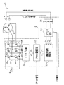
図1に、本実施形態の回転電機駆動装置の概要図を示す。図に示すように、回転電機駆動装置1は、MG2とインバータ3と位置センサ4とパルスセンサ5とを備ている。
【0022】
MG2は、三相交流回転機であって、モータおよび発電機として機能する。MG2は、本発明の回転電機に含まれる。MG2のロータ軸(図略)は、エンジン(図略)のクランク軸とベルト連結されている。位置センサ4は、ロータ軸端に配置された回転部(図略)と、ステータに配置された検出回路(図略)と、からなる。位置センサ4は、MG2のロータ(図略)の磁極位置に対する基準信号を発信している。パルスセンサ5も、位置センサ4と同様に、回転部と検出回路とからなる。パルスセンサ5は、基準信号よりも波長の短いパルス信号を発信している。
【0023】
インバータ3は、パワーMOS(金属−酸化膜−半導体トランジスタ)30とドライブ回路31とPWM重畳回路32と通電相信号作成部33とカウンタ回路34と入力部35とを備えている。入力部35は、位置センサ4およびパルスセンサ5と接続されている。カウンタ回路34は、入力部35と接続されている。また、カウンタ回路34には、外部制御装置(図略)から、位相信号が入力される。通電相信号作成部33は、カウンタ回路34と接続されている。PWM重畳回路32は、通電相信号作成部33と接続されている。また、PWM重畳回路32には、外部制御装置から、PWM信号が入力される。ドライブ回路31は、PWM重畳回路32と接続されている。パワーMOS30は、ドライブ回路31と接続されている。また、パワーMOS30は、前記MG2とバッテリ6との間に介挿されている。
【0024】
次に、本実施形態の回転電機駆動装置のエンジン再始動時における動きについて説明する。例えば、信号停止などにより、イグニッションスイッチがONのまま車両が停止したことが確認されると、エンジンが停止される。そして、車両は、アイドルストップ状態に入る。アイドルストップ状態において、例えば運転者がブレーキペダルをリリースするなどの解除信号が発信されると、エコラン制御装置(図略)がインバータ3にアイドルストップ解除つまりエンジン再始動の指示を出す。この指示を受けて、インバータ3は、MG2を駆動する。
【0025】
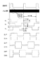
図2に、本実施形態の回転電機駆動装置の信号図を示す。また、図3に、本実施形態の回転電機駆動装置のカウンタ回路の構成図を示す。位置センサ4において、基準信号は、MG2の電気角一回転につき、一回発信される。また、パルスセンサ5において、パルス信号は、MG2の電気角一回転につき、360回発信される。基準信号およびパルス信号は、入力部35を介して、カウンタ回路34に入力される。
【0026】
カウンタ回路34のカウンタ340においては、ある基準信号から次の基準信号までの間におけるパルス信号の数がカウントアップされる。言い換えると、パルス信号のカウントは、基準信号により電気角一回転ごとにリセットされる。
【0027】
比較値回路341において、U相比較値は、180回に設定されている。また、比較値回路342において、V相比較値は、120回に設定されている。また、比較値回路343において、W相比較値は、60回に設定されている。すなわち、各比較値は、電気角に対して120毎のずれを持って設定されている。
【0028】
通電角信号回路344、345、346においては、各相の比較値と、カウントアップされたパルス信号と、の比較が行われる。そして、パルス信号のカウント数がU相比較値である180回になったら、通電角信号回路344において、U相通電角信号をL(Low)からH(High)に切り替える。同様に、パルス信号のカウント数がV相比較値である120回になったら、通電角信号回路345において、V相通電角信号をHからLに切り替える。同様に、パルス信号のカウント数がW相比較値である60回になったら、通電角信号回路346において、W相通電角信号をLからHに切り替える。各相の通電角信号は、パルス信号のカウント数が、切り替え後180回になったら、再び反転される。このようにして、カウンタ回路34において、各相の通電角信号を作成する。
【0029】
通電相信号作成部33は、カウンタ回路34からの通電角信号を受け、通電相の切り替え信号を発信する。その後、PWM重畳回路32で、相電流抑制の為のPWM信号を重畳する。そして、切り替え信号およびPWM信号から得られた駆動信号は、ドライブ回路31からパワーMOS30に出力される。この駆動信号により、パワーMOS30のゲートが駆動される。
【0030】
駆動信号を進角させる場合は、各相の比較値に対して、位相信号を演算する。この演算により、パルス信号の分解能での駆動信号の進角、つまりパルス信号単位での駆動信号の進角を行うことができる。図4に、パルス信号のカウント数で20回分だけ駆動信号を進角させる場合の信号図を示す。この場合は、図に示すように、U相通電角信号の切り替えカウント数を、180回から160回にする(図2参照)。同様に、V相通電角信号の切り替えカウント数を、120回から100回にする。同様に、W相通電角信号の切り替えカウント数を、60回から40回にする。
【0031】
次に、本実施形態の回転電機駆動装置の効果について説明する、本実施形態の回転電機駆動装置1によると、位置センサ4およびパルスセンサ5という二つのセンサから、ロータの磁極位置を検出することができる。このため、センサ配置数が少なくて済む。また、パルス信号は電気角での充分な分解能を有する。このため、ロータの磁極位置の検出精度が高い。また、検出精度が高いにもかかわらず、レゾルバなどが不要である。このため、製造コストが低い。
【0032】
また、本実施形態の回転電機駆動装置によると、通電角信号の切り替えカウント数を変えることにより、駆動信号の進角を行うことができる。言い換えると、パルス信号単位でのきめ細かい進角制御を行うことができる。このため、エンジンの再始動に必要な電動トルクを、MG2が比較的簡単に出力することができる。
【0033】
以上、本発明の回転電機駆動装置の実施の形態について説明した。しかしながら、実施の形態は上記形態に特に限定されるものではない。当業者が行いうる種々の変形的形態、改良的形態で実施することも可能である。
【0034】
例えば、電気角の整数倍で基準信号を発生させてもよい。また、位置センサ4の配置数は一つではなく、二つ以上であってもよい。すなわち、基準信号の発信数は、電気角一回転につき二回以上でもよい。この場合、各基準信号は、互いに異なる信号となるように設定する。また、基準信号間におけるパルス信号の発信数は、360回に限定されない。電気角での充分な分解能があればよい。また、U相比較値、V相比較値、W相比較値は、例えば三相の回転電機の場合、電気角に対して120゜ごとのずれを持っていればよい。
【0035】
【発明の効果】
本発明によると、センサ配置数が少なく、製造コストが低く、ロータの磁極位置の検出精度が高い回転電機駆動装置を提供することができる。
【図面の簡単な説明】
【図1】本発明の回転電機駆動装置の一実施形態の概要図である。
【図2】本発明の回転電機駆動装置の一実施形態の信号図である。
【図3】本発明の回転電機駆動装置の一実施形態のカウンタ回路の構成図である。
【図4】駆動信号を進角させた場合の信号図である。
【図5】従来の回転電機駆動装置の概要図である。
【図6】従来の回転電機駆動装置の信号図である。
【符号の説明】
1:回転電機駆動装置、2:MG(回転電機)、3:インバータ、30:パワーMOS、31:ドライブ回路、32:PWM重畳回路、33:通電相信号作成部、34:カウンタ回路、35:入力部、4:位置センサ、5:パルスセンサ、6:バッテリ。[0001]
TECHNICAL FIELD OF THE INVENTION
The present invention relates to a rotating electric machine drive device used for, for example, an idle stop system.
[0002]
[Prior art]
In a rotating electric machine drive device, an alternating current having a phase and a frequency synchronized with a magnetic pole position, a rotation speed, and the like of a rotor is formed to supply power to a stator coil. Then, drive control of the rotating electric machine is performed. Therefore, detection of the magnetic pole position of the rotor is important for drive control.
[0003]
As shown in FIG. 5, in a rotating electric machine drive device 100 using a three-phase AC rotating machine as an MG (motor generator) 101, a total of three Hall sensors 102, separated by 120 ° in electrical direction in the circumferential direction, 103 and 104 are arranged. The drive control is performed by first detecting the magnetic pole position of the rotor by the Hall sensors 102, 103, and 104 and then outputting a drive signal to the stator coil corresponding to the detected magnetic pole position.
[0004]
Further, in the rotating electric machine driving device described in Patent Document 1, a magnetic pole position of the rotor is detected using a resolver (angle detector) instead of the Hall sensor. Then, drive control is performed.
[0005]
[Patent Document 1]
JP-A-2000-41392 (page 4, FIG. 1)
[0006]
[Problems to be solved by the invention]
By the way, in the rotating electric machine drive device, it is necessary to ensure the detection accuracy of the magnetic pole position of the rotor. However, when the position of the magnetic pole of the rotor is detected using the Hall sensor, the number of Hall sensors corresponding to the number of phases of the stator coil is required to secure the detection accuracy. For example, in the rotating electric machine drive device 100 shown in FIG. 5 described above, a total of three Hall sensors 102, 103, and 104 are required.
[0007]
In this regard, if the position of the magnetic pole of the rotor is detected using a resolver, relatively high detection accuracy can be ensured with only a single resolver. However, if the position of the magnetic pole of the rotor is detected using a resolver, an exciting circuit for the resolver or the like is additionally required. This complicates the peripheral circuit. Therefore, the manufacturing cost increases.
[0008]
In addition, since the engine performs a piston motion having a compression stroke, torque fluctuations and rotational speed fluctuations are large at low speed rotation such as starting. For this reason, in the method of using the Hall sensor signal and outputting the drive signal to the stator coil based on the prediction based on the calculation with the rotation speed, the drive timing may be shifted and the start may fail.
[0009]
The present invention has been completed in view of the above problems. Accordingly, it is an object of the present invention to provide a rotating electric machine drive device having a small number of sensors, a low manufacturing cost, and a high detection accuracy of a magnetic pole position of a rotor.
[0010]
[Means for Solving the Problems]
(1) In order to solve the above problems, a rotating electric machine drive device of the present invention includes a rotating electric machine having a rotor having magnetic poles and a stator having a stator coil, and an inverter for controlling the driving of the rotating electric machine. In the rotating electric machine drive device, further, in the rotor, a position sensor that detects the position of the magnetic pole as a reference signal, and in the rotor, a pulse sensor that detects a pulse signal having a shorter wavelength than the reference signal, Wherein the inverter outputs a drive signal to the stator coil corresponding to the magnetic pole position based on the detected reference signal and pulse signal.
[0011]
That is, the rotating electric machine drive device of the present invention includes the rotating electric machine, the inverter, the position sensor, and the pulse sensor. The rotating electric machine has a rotor having magnetic poles and a stator having stator coils. The position sensor detects the position of the magnetic pole of the rotor as a reference signal. The pulse sensor detects a pulse signal having a shorter wavelength than the reference signal. The pulse signal has a sufficient resolution in electrical angle. In the rotating electric machine drive device of the present invention, the magnetic pole position of the rotor is calculated based on two signals, the reference signal and the pulse signal. Then, a drive signal is output to the stator coil corresponding to the calculated magnetic pole position.
[0012]
ADVANTAGE OF THE INVENTION According to the rotary electric machine drive device of this invention, the detection precision of a rotor magnetic pole position can be ensured, without arrange | positioning the number of sensors according to the number of phases of a stator coil. For this reason, the number of arranged sensors can be reduced. Further, the detection accuracy of the magnetic pole position of the rotor can be secured without disposing a resolver or the like. Therefore, the manufacturing cost is low.
[0013]
(2) Preferably, in order to secure a desired electric torque, the inverter may advance the drive signal in accordance with a rotation speed of the rotating electric machine.
[0014]
When the engine speed increases, it becomes difficult to secure a desired electric torque due to the back electromotive force. Therefore, in order to secure a desired electric torque, in the conventional rotating electric machine drive device shown in FIG. 5 described above, the drive signal is advanced. FIG. 6 shows a signal diagram of the conventional rotating electric machine drive device shown in FIG. Here, as shown in FIG. 5, the Hall sensors 102, 103, and 104 are spaced apart by an electrical angle of 120 °. Therefore, as shown in FIG. 6, the drive signal can be advanced only at every 60 ° step. In this regard, according to this configuration, fine advance control can be performed based on the reference signal and the pulse signal. Therefore, it is easy to secure a desired electric torque.
[0015]
(3) Preferably, in the configuration of (2), the inverter may advance the drive signal in pulse signal units. In this configuration, the drive signal is advanced by the count number of the pulse signal based on the reference signal. The pulse signal has a sufficient resolution in electrical angle. Therefore, according to the present configuration, fine advance control can be performed relatively easily.
[0016]
(4) Preferably, the rotating electric machine is a motor generator used to restart the engine after an idle stop. In the idle stop system, the MG is used to restart the engine of a vehicle that has stopped once, for example, during a traffic jam or waiting for a traffic light. Therefore, the MG is required to have a starting torque from zero rotation. If the accuracy of detecting the position of the magnetic pole of the rotor is low, the desired electric torque cannot be secured, and the start may fail.
[0017]
In this regard, according to the rotating electric machine drive device of the present invention, the detection accuracy of the magnetic pole position is high. Therefore, for example, at the time of MG power generation, that is, when the vehicle is running, the magnetic pole position is calculated from the reference signal and the pulse signal, and the calculated magnetic pole position is always stored, so that the electric torque required for restarting the engine can be secured. it can. Therefore, the rotating electrical machine drive device of the present invention is particularly suitable for use in an idle stop system as in the present configuration.
[0018]
(5) Preferably, in the configuration of the above (4), the motor generator is used in combination with a starter disposed outside, and when the ignition switch is turned on, the engine is started by the starter, and after the ignition switch is turned on, the motor generator is started. It is preferable that the engine be restarted by the motor generator. That is, in this configuration, when the ignition switch is turned on, that is, only the first engine start is performed by the starter, and the subsequent engine restart is performed by the MG. According to this configuration, the load on the starter is reduced as compared with the case where the engine is started and restarted by the starter alone. Therefore, the life of the starter can be extended.
[0019]
BEST MODE FOR CARRYING OUT THE INVENTION
Hereinafter, an embodiment of a rotating electric machine drive device of the present invention will be described. First, the configuration of the rotating electric machine drive device of the present embodiment will be described. The rotating electric machine drive device of the present embodiment is incorporated in an idle stop system.
[0020]
In the idle stop system, when the ignition switch is turned on, the engine is started by a starter provided outside, and after the ignition switch is turned on, the engine is restarted by the MG. Specifically, the engine is started by the starter only when the vehicle speed is 0 and the ignition switch is OFF, and when the vehicle speed is 0 and the ignition switch is ON, the engine is restarted by the MG.
[0021]
FIG. 1 shows a schematic diagram of a rotating electric machine drive device of the present embodiment. As shown in the drawing, the rotating electrical machine drive device 1 includes an MG 2, an inverter 3, a position sensor 4, and a pulse sensor 5.
[0022]
MG2 is a three-phase AC rotating machine, and functions as a motor and a generator. MG2 is included in the rotating electric machine of the present invention. The rotor shaft (not shown) of MG2 is belt-connected to the crankshaft of the engine (not shown). The position sensor 4 includes a rotating part (not shown) arranged at the end of the rotor shaft, and a detection circuit (not shown) arranged on the stator. The position sensor 4 transmits a reference signal for the magnetic pole position of the rotor (not shown) of the MG2. Like the position sensor 4, the pulse sensor 5 also includes a rotating unit and a detection circuit. The pulse sensor 5 emits a pulse signal having a shorter wavelength than the reference signal.
[0023]
The inverter 3 includes a power MOS (metal-oxide-semiconductor transistor) 30, a drive circuit 31, a PWM superimposition circuit 32, an energized phase signal creation unit 33, a counter circuit 34, and an input unit 35. The input unit 35 is connected to the position sensor 4 and the pulse sensor 5. The counter circuit 34 is connected to the input unit 35. In addition, a phase signal is input to the counter circuit 34 from an external control device (not shown). The energized phase signal generator 33 is connected to the counter circuit 34. The PWM superimposing circuit 32 is connected to the energized phase signal generator 33. Further, a PWM signal is input to the PWM superimposing circuit 32 from an external control device. The drive circuit 31 is connected to the PWM superposition circuit 32. The power MOS 30 is connected to the drive circuit 31. The power MOS 30 is interposed between the MG 2 and the battery 6.
[0024]
Next, the operation of the rotating electric machine drive device of the present embodiment when the engine is restarted will be described. For example, when it is confirmed that the vehicle has stopped with the ignition switch turned on due to a stop of a traffic light or the like, the engine is stopped. Then, the vehicle enters an idle stop state. In the idle stop state, when a release signal is transmitted, for example, when the driver releases the brake pedal, the eco-run control device (not shown) instructs the inverter 3 to release the idle stop, that is, restart the engine. In response to this instruction, inverter 3 drives MG2.
[0025]
FIG. 2 shows a signal diagram of the rotating electric machine drive device of the present embodiment. FIG. 3 is a configuration diagram of a counter circuit of the rotating electrical machine drive device according to the present embodiment. In the position sensor 4, the reference signal is transmitted once per rotation of the electrical angle of the MG2. In the pulse sensor 5, a pulse signal is transmitted 360 times per one rotation of the electrical angle of the MG2. The reference signal and the pulse signal are input to the counter circuit 34 via the input unit 35.
[0026]
In the counter 340 of the counter circuit 34, the number of pulse signals between a certain reference signal and the next reference signal is counted up. In other words, the count of the pulse signal is reset by one rotation of the electrical angle by the reference signal.
[0027]
In the comparison value circuit 341, the U-phase comparison value is set to 180 times. In the comparison value circuit 342, the V-phase comparison value is set to 120 times. In the comparison value circuit 343, the W-phase comparison value is set to 60 times. That is, each comparison value is set with a shift of 120 every electrical angle.
[0028]
In the energization angle signal circuits 344, 345, and 346, the comparison value of each phase is compared with the counted up pulse signal. When the count number of the pulse signal reaches 180, which is the U-phase comparison value, the energization angle signal circuit 344 switches the U-phase energization angle signal from L (Low) to H (High). Similarly, when the count number of the pulse signal reaches 120, which is the V-phase comparison value, the conduction angle signal circuit 345 switches the V-phase conduction angle signal from H to L. Similarly, when the count number of the pulse signal reaches 60, which is the W-phase comparison value, the conduction angle signal circuit 346 switches the W-phase conduction angle signal from L to H. The energization angle signal of each phase is inverted again when the count number of the pulse signal becomes 180 after switching. In this manner, the energization angle signal of each phase is created in the counter circuit 34.
[0029]
The energized phase signal generator 33 receives the energized angle signal from the counter circuit 34 and transmits a signal for switching the energized phase. After that, the PWM signal for suppressing the phase current is superimposed by the PWM superimposing circuit 32. The drive signal obtained from the switching signal and the PWM signal is output from the drive circuit 31 to the power MOS 30. The gate of the power MOS 30 is driven by this drive signal.
[0030]
When the drive signal is advanced, a phase signal is calculated for the comparison value of each phase. By this calculation, the advance of the drive signal at the resolution of the pulse signal, that is, the advance of the drive signal in pulse signal units can be performed. FIG. 4 shows a signal diagram in a case where the drive signal is advanced by 20 times in the count number of the pulse signal. In this case, as shown in the figure, the switching count of the U-phase conduction angle signal is changed from 180 to 160 (see FIG. 2). Similarly, the switching count of the V-phase conduction angle signal is changed from 120 times to 100 times. Similarly, the switching count of the W-phase conduction angle signal is changed from 60 times to 40 times.
[0031]
Next, the effect of the rotating electric machine driving device of the present embodiment will be described. According to the rotating electric machine driving device 1 of the present embodiment, the position sensor 4 and the pulse sensor 5 detect the magnetic pole position of the rotor. Can be. For this reason, the number of arranged sensors can be reduced. Further, the pulse signal has a sufficient resolution in electrical angle. Therefore, the detection accuracy of the magnetic pole position of the rotor is high. Also, despite the high detection accuracy, a resolver or the like is not required. Therefore, the manufacturing cost is low.
[0032]
Further, according to the rotating electrical machine drive device of the present embodiment, the drive signal can be advanced by changing the switching count of the energization angle signal. In other words, fine advance control can be performed in pulse signal units. Therefore, the MG2 can relatively easily output the electric torque required for restarting the engine.
[0033]
The embodiments of the rotating electric machine drive device of the present invention have been described above. However, embodiments are not particularly limited to the above embodiments. Various modifications and improvements that can be made by those skilled in the art are also possible.
[0034]
For example, the reference signal may be generated at an integral multiple of the electrical angle. The number of the position sensors 4 is not limited to one, but may be two or more. That is, the number of transmissions of the reference signal may be two or more per electric angle rotation. In this case, each reference signal is set so as to be different from each other. Further, the number of pulse signals transmitted between the reference signals is not limited to 360. It suffices if there is sufficient resolution in electrical angle. Further, the U-phase comparison value, the V-phase comparison value, and the W-phase comparison value need only have a deviation of 120 ° from the electrical angle in the case of, for example, a three-phase rotating electric machine.
[0035]
【The invention's effect】
According to the present invention, it is possible to provide a rotating electric machine drive device having a small number of sensors, a low manufacturing cost, and a high detection accuracy of a magnetic pole position of a rotor.
[Brief description of the drawings]
FIG. 1 is a schematic view of an embodiment of a rotating electric machine drive device of the present invention.
FIG. 2 is a signal diagram of one embodiment of a rotating electric machine drive device of the present invention.
FIG. 3 is a configuration diagram of a counter circuit of one embodiment of the rotating electrical machine drive device of the present invention.
FIG. 4 is a signal diagram when a drive signal is advanced.
FIG. 5 is a schematic view of a conventional rotating electric machine drive device.
FIG. 6 is a signal diagram of a conventional rotating electrical machine drive device.
[Explanation of symbols]
1: rotating electric machine drive device, 2: MG (rotating electric machine), 3: inverter, 30: power MOS, 31: drive circuit, 32: PWM superimposition circuit, 33: energized phase signal generator, 34: counter circuit, 35: Input unit, 4: Position sensor, 5: Pulse sensor, 6: Battery.