【0001】
【発明の属する技術分野】
本発明はディスクアレイ装置に関し、特に電源瞬断によるシステムの不具合を防ぐことができるディスクアレイ装置に関する。
【0002】
【従来の技術】
一般的なディスクアレイ装置に関して、図2を使用して説明する。ディスクアレイ装置9は、一般的に半導体メモリで構成されたキャッシュメモリ6を使用して性能向上を図っている。ホストからのライトコマンド10を受け取るとホスト制御部3ではディスク8に書き込むべきデータを一旦キャッシュメモリ6に格納しホストへコマンド終了10を報告する。そして、ホストからのコマンド処理を行っていない閑散時にキャッシュメモリ6に格納しておいたライトデータをキャッシュメモリ制御部5およびディスク制御部7に依ってディスク8の所定位置へ書き込む作業を行う。ホストからのライトコマンド10に関しては、一度使用したデータは再度使用される頻度が高いと判断しキャッシュメモリ6に格納しておき、ホストから再度同一データを読み出すコマンド10を受信すると、ディスク8からではなくキャッシュメモリ6から読み出す動作を行う。ディスク10へのアクセス時間よりキャッシュメモリ6へのアクセス時間の方が高速であることから装置全体の性能向上を図ることができる。図3は電源1の構成を示すブロック図である。AC−DC変換回路はAC供給11を受けてAC−DC変換を行い、電源制御部4にDC供給12の出力を行う。
【0003】
しかしながら、キャッシュメモリ6に格納したライトデータをディスクに書き込む前に停電等でAC供給11が絶たれた場合、電源1にてDC供給12が無くなりメモリからディスクへの書き込みができない状態になり、キャッシュデータを消失してしまうことになる。既にコマンド処理は終了しているため、ユーザデータ消失という致命的な障害に至ってしまう。この様な障害が発生しないために、バッテリ・バックアップ・ユニット(以下、BBUと言う)2の蓄電池によりDC供給を継続しキャッシュデータバックアップを行うのが一般的である。また、バックアップ方式は、保存すべきキャッシュメモリのみに電源を供給し続けるタイプが一般的である。
【0004】
つまり、BBU2によるバックアップ中は可能な限り低消費電力化を図り、バッテリによる保持時間を増大させる必要がある。そのため、キャッシュメモリとして採用されるSDRAM(シクロナス・ダイナミックRAM)は、バックアップ時にセルフリフレッシュモードに設定し、またSDRAMへの供給すべきクロックを停止させることで更なる低消費電力化を図っている。そのため、電源が停止する前に、CPUはバックアップ動作に以降する指示を受けてメモリのセルフリフレッシュ設定およびクロック停止の処理を行う必要がある。この為のバックアップ動作指示がプリパワーオフ信号13である。
【0005】
電源1のAC低下検出回路16にてAC供給を監視し、停止又は異常を検出することでDC供給12が絶たれる前にその事実を予告するためのプリパワーオフ信号13を生成する。通常状態ではバッテリ出力を停止しておき、電源1が検出するプリパワーオフ信号13を受け取った時点で、バッテリによりバックアップすべきデータがキャッシュ6内部に存在するかを判断し、必要であればBBU出力指示信号14を送出しバッテリ出力を供給開始する。
【0006】
AC電源が瞬断してもプリパワーオフが検出されない程度であれば、バックアップモードに遷移することなく通常のシステム運用が継続される。また、一端プリパワーオフが検出されるような瞬断が生じた場合でバックアップモードに遷移したとしても、DC供給が停止してしまえば、その後のDC復帰時に電源投入と同様のリセット機能により装置はメモリデータを残したまま初期化され継続運用することが可能となる。
【0007】
【発明が解決しようとする課題】
プリパワーオフ信号13を受け取ってバックアップモードに遷移する際は、バッテリーによるメモリの保持時間を増大させることを目的に、メモリへのクロックを停止させかつCPUを停止させるなど徹底的な低消費電力化を図っている。そのため、一旦バックアップモードに遷移した後は、CPU制御のファームウエアにより各種状態監視を行うことが不可能である。つまり、プリパワーオフが検出されたがDC電源の停止まで至らない瞬断状態が発生した場合、ファームウエア制御によりバックアップモードに遷移した状態が継続されてしまい、供給電源が瞬断後に復電しても装置として継続運用することができず、電源の再投入が必要となる。つまり、ある条件下で電源が瞬断した場合、データの保証は行われるがシステム運用の継続性が損なわれる場合がある。
【0008】
以上説明したような従来のディスクアレイ装置では、キャッシュデータの大容量化に伴いプリパワーオフ検出レベルの感度が向上され、一旦プリパワーオフが検出されDC出力断にまで至らない様な瞬断が生じた場合、その後電源が復帰したとしてもバックアップモードに遷移したまま装置としては継続運用することができず、電源の再投入が必要となると言う問題がある。なお、いかなる瞬断に対しても確実に電源復帰させる方法が特許文献1に記載されている。
【0009】
【特許文献1】
特開2001−175365号公報
【0010】
【課題を解決するための手段】
本発明のディスクアレイ装置は、AC電力供給を受けてDC電力を供給する電源部と、前記DC電力をディスクアレイ装置に供給する電源制御部と、前記DC電力を蓄電し、前記電源部からの供給停止時に前記電源制御部の指示を受けて前記電源制御部に電力供給を行うバッテリーバックアップユニットとを有するディスクアレイ装置において、前記電源部は、前記AC電力供給の低下を検出して前記電源制御部にプリパワーオフ信号を出力するAC低下検出部と、前記プリパワーオフ信号を受けて一定時間DC供給停止を指示するタイマー部とで構成され、前記AC電力供給が復電し、かつ前記DC供給停止指示が解除された際にDC供給を再開することを特徴とする。
【0011】
【発明の実施の形態】
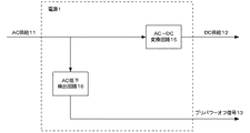
本発明の一実施例について図を参照して以下に説明する。図1は、本発明におけるディスクアレイ装置の電源制御部の一例を表すブロック図である。AC供給11を受けてAC−DC変換回路部15ではディスクアレイ装置内部にDC供給12を供給し続ける。電源1内部のAC低下検出回路16では、AC入力の低下ならびに異常を検出し、AC−DC変換回路15からのDC供給12が停止する前にプリパワーオフ信号13を送出する。ここまでは、従来の電源制御を表す図2のブロック図と同様である。
【0012】
本発明は図1に示すように、プリパワーオフ信号13を受け取り一定時間DC供給停止信号18を送出するタイマー回路17を持ち、DC供給停止信号18を受け強制的にDC供給12を停止させる機能をAC−DC変換回路15に持つことを特徴としている。AC−DC変換回路15はAC供給11が復電してもDC供給停止信号18を受信し続けている限りDC供給12を停止する。DC供給停止信号18が解除され、かつAC供給11が行われていればDC供給12を再開する。
【0013】
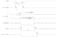
次に本発明の動作に於けるタイミング関係を図4に示す。まず、AC供給の落ち込みを検出しプリパワーオフ信号をアクティブローにする(タイミングa)。次に、タイマー回路では、バックアップモードに遷移するための必要時間監視してDC供給停止信号をアクティブローとする(タイミングb)。この間にファームウエアはメモリへのクロック停止やCPUのクロック停止によりバックアップモードに遷移する。更にDC復帰後に装置が再起動に掛かるだけの十分な時間だけプリパワーオフ信号を監視し(タイミングc)、その間だけDC供給停止信号をDC供給がオフするように保持する(タイミングd)。その間AC供給が復電してもDC供給の停止状態はそのままとする。そしてDC供給停止信号が解除された時点で図4の様にAC供給が復電していた場合にはDC供給も復帰し、パワーオンリセット信号が解除され、初期の電源供給時と同様のシーケンスで装置が起動状態に遷移する(タイミングe)。
【0014】
その結果、通常電源立ち上げ時と同様に、キャッシュデータを残したまま初期化(リブート)が行われ、バックアップモード時に電源を再投入したと同様の復元処理が行われる。タイミングcに於いてそのままAC供給が絶たれれば、当然バックアップモードに遷移したまま次の電源復帰を待ち、タイミングd以降は制御電源が断たれるため行われない。
【0015】
【発明の効果】
以上の様に本発明によれば、一旦プリパワーオフが検出された場合、例え入力電源が復帰したとしても、必ず一定期間DC電源出力が停止されるようにDC電源供給を制御する電源回路構成とすることにより、パワーオフが検出されDC電源が停止されない状態の瞬断が生じた場合でもバックアップモードのまま停止し続けることが避けられ、再度電源を投入すると言う人手介入の作業無しにシステムを運用し続けることが可能となり、瞬断に対する耐力を向上したディスクアレイ装置を提供することができる。
【図面の簡単な説明】
【図1】本発明の構成を示すブロック図である。
【図2】一般的なディスクアレイの構成を示すブロック図である。
【図3】電源1の内部構成を示すブロック図である。
【図4】本発明の動作を示すタイミングチャートである。
【符号の説明】
1 電源
2 BBU
3 ホスト制御部
4 電源制御部
5 キャッシュメモリ制御部
6 キャッシュメモリ
7 ディスク制御部
8 ディスク
9 ディスクアレイ
10 ホストコマンドデータ
11 AC供給
12 DC供給
13 プリパワーオフ信号
14 BBU出力指示信号
15 AC−DC変換回路
16 AC低下検出回路
17 タイマー回路[0001]
TECHNICAL FIELD OF THE INVENTION
The present invention relates to a disk array device, and more particularly, to a disk array device that can prevent system failure due to a momentary power interruption.
[0002]
[Prior art]
A general disk array device will be described with reference to FIG. The performance of the disk array device 9 is improved by using the cache memory 6 generally formed of a semiconductor memory. Upon receiving the write command 10 from the host, the host controller 3 temporarily stores the data to be written to the disk 8 in the cache memory 6 and reports the command end 10 to the host. Then, the write data stored in the cache memory 6 is written to a predetermined position of the disk 8 by the cache memory control unit 5 and the disk control unit 7 during off hours when no command processing from the host is performed. Regarding the write command 10 from the host, the data used once is judged to be frequently used again and is stored in the cache memory 6, and when the command 10 for reading the same data is received again from the host, the disk 8 The operation for reading from the cache memory 6 is performed. Since the access time to the cache memory 6 is faster than the access time to the disk 10, the performance of the entire apparatus can be improved. FIG. 3 is a block diagram illustrating a configuration of the power supply 1. The AC-DC conversion circuit receives the AC supply 11, performs AC-DC conversion, and outputs the DC supply 12 to the power supply control unit 4.
[0003]
However, if the AC power supply 11 is cut off due to a power failure or the like before the write data stored in the cache memory 6 is written to the disk, the DC power supply 12 is lost at the power supply 1 and the memory cannot be written to the disk. Data will be lost. Since the command processing has already been completed, a catastrophic failure of user data loss will occur. In order to prevent such a failure from occurring, it is common practice to continue DC supply by using a storage battery of a battery backup unit (hereinafter, referred to as BBU) 2 to perform cache data backup. In general, the backup method is a type in which power is continuously supplied only to a cache memory to be stored.
[0004]
That is, it is necessary to reduce the power consumption as much as possible during the backup by the BBU 2 and to increase the battery holding time. Therefore, the SDRAM (cyclonas dynamic RAM) used as a cache memory is set in a self-refresh mode at the time of backup, and the clock to be supplied to the SDRAM is stopped to further reduce power consumption. Therefore, before the power is turned off, the CPU needs to receive the instruction following the backup operation and perform the self-refresh setting of the memory and the clock stop processing. The backup operation instruction for this is the pre-power-off signal 13.
[0005]
The AC supply detection circuit 16 of the power supply 1 monitors the AC supply, and detects a stop or abnormality to generate a pre-power-off signal 13 for notifying the fact before the DC supply 12 is cut off. In the normal state, the battery output is stopped, and upon receiving the pre-power-off signal 13 detected by the power supply 1, it is determined whether data to be backed up by the battery exists in the cache 6, and if necessary, the BBU The output instruction signal 14 is transmitted to start supplying the battery output.
[0006]
If pre-power-off is not detected even if the AC power supply is momentarily interrupted, normal system operation is continued without transition to the backup mode. Further, even if the mode is changed to the backup mode in the case of a momentary interruption such that the pre-power-off is detected once, if the DC supply is stopped, the device is reset by the same reset function as the power-on when the DC is restored thereafter. Is initialized with the memory data remaining, and can be operated continuously.
[0007]
[Problems to be solved by the invention]
When receiving the pre-power-off signal 13 and transitioning to the backup mode, the power consumption is thoroughly reduced by stopping the clock to the memory and stopping the CPU for the purpose of increasing the retention time of the memory by the battery. I am planning. For this reason, once the mode has transitioned to the backup mode, it is impossible to monitor various states using firmware controlled by the CPU. In other words, if a pre-power-off is detected, but an instantaneous interruption state that does not lead to the stop of the DC power supply occurs, the state of transition to the backup mode by the firmware control is continued, and the power supply is restored after the instantaneous interruption of the power supply. However, the device cannot be continuously operated, and the power must be turned on again. That is, when the power supply is momentarily interrupted under certain conditions, data is guaranteed, but continuity of system operation may be impaired.
[0008]
In the conventional disk array device as described above, the sensitivity of the pre-power-off detection level is improved with an increase in the cache data capacity, and a momentary interruption such that the pre-power-off is detected once and the DC output is not interrupted is detected. When this occurs, there is a problem in that even if the power is restored thereafter, the apparatus cannot be continuously operated with the transition to the backup mode, and the power must be turned on again. A method for surely restoring the power supply in response to any instantaneous interruption is described in Patent Document 1.
[0009]
[Patent Document 1]
JP 2001-175365 A
[Means for Solving the Problems]
A disk array device of the present invention includes a power supply unit that receives AC power supply and supplies DC power, a power supply control unit that supplies the DC power to the disk array device, stores the DC power, and supplies the DC power from the power supply unit. In a disk array device having a battery backup unit that supplies power to the power supply control unit upon receiving an instruction from the power supply control unit when supply is stopped, the power supply unit detects the decrease in the AC power supply and performs the power control. And a timer unit for receiving a signal of the pre-power-off signal and instructing the DC power supply to stop for a certain period of time. When the supply stop instruction is released, the DC supply is restarted.
[0011]
BEST MODE FOR CARRYING OUT THE INVENTION
One embodiment of the present invention will be described below with reference to the drawings. FIG. 1 is a block diagram illustrating an example of a power supply control unit of a disk array device according to the present invention. Upon receiving the AC supply 11, the AC-DC conversion circuit unit 15 continues to supply the DC supply 12 to the inside of the disk array device. An AC drop detection circuit 16 inside the power supply 1 detects a drop in AC input and an abnormality, and sends a pre-power-off signal 13 before the DC supply 12 from the AC-DC conversion circuit 15 stops. Up to this point, it is the same as the block diagram of FIG. 2 showing the conventional power supply control.
[0012]
As shown in FIG. 1, the present invention has a timer circuit 17 which receives a pre-power-off signal 13 and sends out a DC supply stop signal 18 for a certain period of time, and forcibly stops the DC supply 12 in response to the DC supply stop signal 18. In the AC-DC conversion circuit 15. The AC-DC conversion circuit 15 stops the DC supply 12 as long as the DC supply stop signal 18 is continuously received even if the AC supply 11 is restored. If the DC supply stop signal 18 is released and the AC supply 11 is being performed, the DC supply 12 is restarted.
[0013]
FIG. 4 shows a timing relationship in the operation of the present invention. First, a fall in AC supply is detected, and the pre-power-off signal is set to active low (timing a). Next, the timer circuit monitors the necessary time for transition to the backup mode, and sets the DC supply stop signal to active low (timing b). During this time, the firmware shifts to the backup mode by stopping the clock to the memory or the CPU. Further, the pre-power-off signal is monitored for a time sufficient for the apparatus to restart after the DC return (timing c), and the DC supply stop signal is held so that the DC supply is turned off during this time (timing d). In the meantime, even if the AC supply is restored, the DC supply stop state is kept as it is. If the AC supply is restored as shown in FIG. 4 at the time when the DC supply stop signal is released, the DC supply is also restored, the power-on reset signal is released, and the same sequence as in the initial power supply is performed. Then, the device transits to the activated state (timing e).
[0014]
As a result, the initialization (reboot) is performed with the cache data remaining as in the case of the normal power-on, and the same restoration processing as when the power is turned on again in the backup mode is performed. If the AC supply is cut off at the timing c, the control mode is naturally changed to the backup mode and the next power recovery is awaited.
[0015]
【The invention's effect】
As described above, according to the present invention, once the pre-power-off is detected, even if the input power is restored, the power supply circuit configuration that controls the DC power supply so that the DC power output is always stopped for a certain period of time. By doing so, it is possible to prevent the system from continuing to be stopped in the backup mode even if a momentary interruption occurs in which the power supply is detected and the DC power supply is not stopped. It is possible to provide a disk array device that can be continuously operated and has improved resistance to instantaneous interruption.
[Brief description of the drawings]
FIG. 1 is a block diagram showing a configuration of the present invention.
FIG. 2 is a block diagram showing a configuration of a general disk array.
FIG. 3 is a block diagram showing an internal configuration of the power supply 1.
FIG. 4 is a timing chart showing the operation of the present invention.
[Explanation of symbols]
1 power supply 2 BBU
3 Host control unit 4 Power control unit 5 Cache memory control unit 6 Cache memory 7 Disk control unit 8 Disk 9 Disk array 10 Host command data 11 AC supply 12 DC supply 13 Pre-power off signal 14 BBU output instruction signal 15 AC-DC conversion Circuit 16 AC drop detection circuit 17 Timer circuit