JP2004143677A - Carrying in/out device of construction machine and material - Google Patents
Carrying in/out device of construction machine and material Download PDFInfo
- Publication number
- JP2004143677A JP2004143677A JP2002306524A JP2002306524A JP2004143677A JP 2004143677 A JP2004143677 A JP 2004143677A JP 2002306524 A JP2002306524 A JP 2002306524A JP 2002306524 A JP2002306524 A JP 2002306524A JP 2004143677 A JP2004143677 A JP 2004143677A
- Authority
- JP
- Japan
- Prior art keywords
- building
- guide
- guide rails
- equipment
- carrying
- Prior art date
- Legal status (The legal status is an assumption and is not a legal conclusion. Google has not performed a legal analysis and makes no representation as to the accuracy of the status listed.)
- Pending
Links
Images


Landscapes
- Movable Scaffolding (AREA)
- Conveying And Assembling Of Building Elements In Situ (AREA)
Abstract
Description
【0001】
【発明の属する技術分野】
本発明は建設中の建築物の上下階の間で仮設機材や建築材料などの建築機材を移動する際に使用する建築機材の搬出入装置に関する。
【0002】
【従来の技術】
オフィスビルやマンションなどの中層ないし高層の建築物を建築する際には、下側階から順次上側階を建築していくことになり、各階の基本的な骨格が建築された後には、建築物内部の配管作業、コンクリート打ち作業および内装作業などの各種作業が行われる。これらの作業を行うために、それに要する型枠、仮設足場および仮設走行台車などの建築機材や建築物に取り付けられる配管などの建築機材を外部から各階に搬入する建築機材の搬入作業を行う必要がある。
【0003】
建築機材を建築物に搬入するために建築物に固定された架台に荷揚げ機を取り付けて、その荷揚げ機により建築機材を地上から架台に吊り上げた後に、建築物内に搬入するようにしている(たとえば、特許文献1参照)。
【0004】
【特許文献1】
特開2000−145129号公報
【0005】
【発明が解決しようとする課題】
このように建築物に固定される架台に荷揚げ機を取り付けるようにした場合には、地上から建築物の所定階にまで建築機材を搬入することはできるが、上側の階に建築機材を搬送することは困難である。建築作業を行う場合には、たとえば、所定階の部分の工事が終了した後に、その階の建築に使用した型枠や仮設足場などの建築機材を上側階に搬送するようにしているが前述のように固定式の架台を使用した場合には、下側階から上側階に建築機材を搬送することはできない。このため、建築機材を下側階から上側階に使い回す場合には、従来では、建築物の外側に構築された足場を利用して作業者が人手によって建築機材を運搬する必要があり、作業が危険なだけでなく、時間がかかることになる。
【0006】
本発明の目的は、建築物内への建築機材の搬入を容易に短時間で行い得るようにすることにある。
【0007】
本発明の他の目的は、建築作業を短期間で迅速に行い得るようにすることにある。
【0008】
【課題を解決するための手段】
本発明の建築機材の搬出入装置は、建築物に対して建築機材を搬出入する建築機材の搬出入装置であって、前記建築物の外面に沿って上下方向に相互に平行に配置される複数のガイドレールと、それぞれの前記ガイドレールを前記建築物に着脱自在に締結する締結具と、それぞれの前記ガイドレールに沿って転動するローラがそれぞれ設けられた複数のガイドポストと、前記ガイドポストに取り付けられる昇降ステージを備え、前記ガイドレールに沿って上下方向に移動する昇降台と、前記昇降台を前記ガイドレールに沿って上下方向に駆動する駆動手段とを有することを特徴とする。
【0009】
本発明の建築機材の搬出入装置は、建築物に対して建築機材を搬出入する建築機材の搬出入装置であって、前記建築物の外面に沿って上下方向に相互に平行に配置されたガイドレールに沿って転動するローラがそれぞれ設けられた複数のガイドポストと、前記ガイドポストに取り付けられる昇降ステージを備え、前記ガイドレールに沿って上下方向に移動する昇降台と、所定位置で停止させた状態のもとで前記昇降台に前記建築機材を収容し、前記昇降台により建築物の上側階に前記建築機材を搬送することを特徴とする。
【0010】
本発明の建築機材の搬出入装置は、建築物に対して建築機材を搬出入する建築機材の搬出入装置であって、前記建築物の外面に沿って上下方向に相互に平行となって配置され、昇降台に取り付けられる複数のガイドポストに設けられたローラを案内する複数のガイドレールと、それぞれの前記ガイドレールを前記建築物に着脱自在に締結する締結具とを有し、前記昇降台を前記ガイドレールに沿って上下方向に案内するとともに前記昇降台を所定位置で停止させた状態のともで前記建築機材を建築物内に搬入することを特徴とする。
【0011】
本発明の建築機材の搬出入装置は、前記昇降台を前記ガイドレールに対して所定の位置でロックするロック部材を有することを特徴とする。また、前記ガイドレールは前記建築物の1階相当分ないし複数回相当分の長さを有し、前記建築物の高さに応じて前記ガイドレールを連結することを特徴とする。さらに、前記昇降台を所定の位置に停止した状態のもとで地上側から前記建築機材を前記昇降台に搬入することを特徴とする。
【0012】
本発明の建築機材の搬出入装置は、建築物に連結状態となって配置された複数のガイドレールのうち最下側のガイドレールを取り外し、最上側にガイドレールを連結し、連結状態の複数のガイドレールを建築物の上方側に移動させることを特徴とする。また、前記駆動手段は前記建築物または前記昇降台に設けられる昇降機であることを特徴とする。
【0013】
【発明の実施の形態】
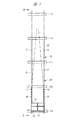
以下、本発明の実施の形態を図面に基づいて詳細に説明する。図1は本発明の一実施の形態である建築機材の搬出入装置を示す正面図であり、図2は図1におけるII−II線に沿う断面図である。図1および図2には建築中の建築物10の一部が示されており、たとえば符号11aは建築物10の2階部分のベランダを示す。これらの図には2階部分から6階部分のベランダ11b〜11eが示されており、6階部分はまだ完成していない状態となって示されている。
【0014】
2階部分の骨格の建築が完了した後には、その内部における各種作業を行うために、型枠や仮設足場などの建築機材が建築物内部に搬入される。そのために、建築物の外側には上下動案内装置20が着脱自在つまり取り外し自在に装着され、この上下動案内装置20には昇降台30が組み付けられることになる。
【0015】
図3は上下動案内装置20を示す斜視図であり、図4は昇降台30を示す斜視図である。図3に示すように、上下動案内装置20はそれぞれ断面コの字形状となったチャンネル材からなる2本のガイドレール21,22を有している。これらのガイドレール21,22は相互に内側面が向き合うように対向し、下端部で連結棒材23により相互に所定の間隔となるようにして連結されている。この連結棒材23としては断面L字形状のチャンネル材が使用されているが、角パイプや角棒あるいは板材を使用するようにしても良い。それぞれのガイドレール21,22の下端部には連結棒材23を介して脚部材24a,24bが取り付けられており、脚部材24a,24bの長手方向中央部とガイドレール21,22の間には補強棒材25a,25bが固定されている。なお、ガイドレール21,22の上端部相互間に連結棒材23と同様の連結部材を取り付けて、連結強度を高めるようにしても良い。
【0016】
前述した脚部材24a,24bは、ガイドレール21,22を建築物10に取り付ける際には、建築物10のベランダ上面に配置されることになる。ガイドレール21,22を建築物に着脱自在に締結するために、図2および図3に示すように、締結具として締結支柱26が脚部材24a,24bと上側階のベランダの下面との間に組み付けられる。この締結支柱26は2本のパイプ部26a,26bとこれらの間に組み込まれたねじ部27とを有する。このねじ部27に設けられたハンドル27aを操作して、ねじ部27を回転させてパイプ部26a,26bを相互に接近させたり離反させることにより、締結支柱26の全長を伸縮させることができる。したがって、締結支柱26を収縮させた状態で脚部材24a,24bの上に締結支柱26を配置した後に、締結支柱26の全長を長くすることにより、ガイドレール21,22は脚部材24a,24bおよび締結支柱26を介して建築物10に締結されることになる。
【0017】
それぞれのガイドレール21,22は上下方向に隣り合うベランダ相互間の距離に対応した長さを有しており、たとえば3.8m〜4m程度の長さに設定されている。したがって、建築作業が進行するに伴って順次上側階の部分の骨格の建築が終了すると、下側の上下動案内装置20の上側に他の上下動案内装置20を連結することになる。ガイドレール21,22を連結するために、ガイドレール21,22の両端部には、連結金具28が取り付けられるようになっている。連結金具28には複数の貫通孔29aが形成され、貫通孔29aに対応してガイドレール21,22の両端部にはねじ孔29bが形成されている。したがって、貫通孔29aを貫通させてねじ孔29bに図示しないボルトをねじ結合させることにより、連結金具28を用いてガイドレール21,22を連結することができ、これにより複数の上下動案内装置20を任意の段数だけ連結することができる。ただし、ガイドレール21,22を上下に連結するための連結手段としては、図示する連結金具28に限られることなく、種々のタイプの連結金具を使用することができる。
【0018】
一方、昇降台30は図4に示すように、ガイドレール21,22に対応する2本のガイドポスト31,32を有し、これらのガイドポスト31,32は四辺形の昇降ステージ33の基端部に取り付けられている。図示する場合にはそれぞれのガイドポスト31,32は昇降ステージ33に固定されたブラケット34にピン35により結合されているが、ガイドポスト31,32を直接昇降ステージ33に溶接などにより固定するようにしても良い。ただし、ガイドポスト31,32とをピン35を用いて結合するようにすると、建築現場において昇降台30を組み立てることができ、建築現場まで昇降台30を分解した状態で搬送することができる。また、建築現場まではピン35を中心にガイドポスト31,32を昇降ステージ33に対して折り畳んだ状態でトラックなどにより搬送するようにしても良い。
【0019】
昇降ステージ33の先端部はチェーン36によってガイドポスト31,32の上端部に連結され、チェーン36によって昇降ステージ33はガイドポスト31,32に対してほぼ直角となって建築物10の外方に水平に突出することになる。チェーン36を昇降ステージ33とガイドポスト31,32とを連結するために、昇降ステージ33の先端部の両側にはブラケット37が固定され、ガイドポスト31,32にはブラケット38が固定されている。
【0020】
図4に示すチェーン36に代えてワイヤー、ロープあるいは筋交いなど他の部材を用いるようにしても良い。また、昇降ステージ33としては、チャンネル材からなる四辺形の枠体にエキスパンドメタルを取り付けるようにして形成しても良く、四辺形の金属製の板材を用いるようにしても良い。
【0021】
昇降ステージ33の先端部と両側部には、手摺り39が取り付けられており、作業者が昇降ステージ33の上で建築機材の搬入および搬出作業を行う場合の作業者の安全が図られており、さらに昇降ステージ33の上に収容された建築機材が昇降台30から落下することが防止される。手摺り39は昇降ステージ33から取り外し自在となっており、建築現場において手摺り39を昇降ステージ33に装着することができる。ただし、手摺り39を予め昇降ステージ33に固定するようにしても良い。また、地上側から昇降台30に建築機材を搬入する際に、手摺り39のたとえば先端側を取り外し得るようにしても良い。さらに、手摺り39を昇降ステージ33に折り畳むようにしても良い。
【0022】
それぞれのガイドポスト31,32の上端部と下端部にはそれそれローラ41が回転自在に取り付けられている。それぞれのローラ41はガイドポスト31,32の外面に取り付けられ、ガイドレール21,22の内部に入り込むようになっている。したがって、建築現場において建築物にガイドレール21,22を締結した状態のもとで、ガイドレール21,22にローラ41を滑り込ませることによって、昇降台30をガイドレール21,22に組み付けることができる。それぞれのガイドポスト31,32には2つずつローラ41が取り付けられているが、3つずつあるいはそれ以上取り付けるようにしても良い。
【0023】
ガイドレール21,22に組み付けられた昇降台30を上下方向に搬送するために、建築物に設けられたクレーン、ウインチあるいはホイストなどからなり駆動手段を構成する昇降機のワイヤ42が昇降台30に取り付けられるようになっている。ワイヤ42を昇降機30に取り付けるために、ガイドポスト31,32の上端部にはワイヤ42が係合するフック43が設けられている。フック43はガイドポスト31,32に一体に設けるようにしても良く、ガイドポスト31,32にねじ止めしたり溶接して固定するようにしても良い。したがって、昇降台30は昇降機によってガイドレール21,22に沿って上昇移動および下降移動することができる。比較的重量の嵩むガイドレール21,22を建築物10に取り付け、ガイドレール21,22に沿って昇降台30を上下動させることにより、昇降台30自体を軽量化することが可能となり、円滑に昇降台30を上昇移動させることができる。また、昇降機のワイヤ42を停止させておくと、昇降台30を所定の位置で停止させておくことができる。
【0024】
昇降台30をガイドレール21,22に対して所定の位置でロックさせることにより、昇降機のワイヤ42を使用することなく、昇降台30を停止させることができる。そのため、図3に示すようにそれぞれのガイドレール21,22にはロックピン44が貫通する取付孔45が形成され、図4に示すように取付孔45に対応させてガイドポスト31,32には取付孔46が形成されている。したがって、ガイドレール21,22とガイドポスト31,32との間に任意の本数のロックピン44を取り付けることによって、昇降台30を上下動案内装置20に対してロックつまり締結させることができる。図示する場合にはロック部材としてロックピン44が用いられているが、昇降台30を上下動案内装置20にロックするものであれば、ロックピン44に限られることはない。
【0025】
次に、上述した建築機材の搬出入装置を用いて建築作業を行う手順について説明する。上下動案内装置20は図3に示されるように建築現場で組み立てられ、昇降台30は図4に示されるように建築現場で組み立てられる。たとえば、建築物10の4階部分までの建築が所定の段階まで終了した後に、まず、2階から4階のベランダ11a〜11cに上下動案内装置20を締結する。締結するには、ガイドレール21,22を建築物10の外側に配置して締結支柱26を脚部材24a,24bと上側階の下面との間に取り付ける。これにより、脚部材24a,24bの部分でガイドレール21,22は強固に締結されるとともに、上下方向にガイドレール21,22が連結される。連結する際には連結金具28を用いて下側のガイドレール21,22に上側のガイドレール21,22を連結することになる。
【0026】
次いで、昇降台30のローラ41をガイドレール21,22に滑り込ませて昇降台30を上下動案内装置20に組み付ける。このときには、クレーンやホイストなどの駆動手段としての昇降機のワイヤ42をフック43に引っかけて昇降機により昇降台30を上昇移動させる。ただし、2階部分に上下動案内装置20が締結された状態のもとで昇降台30をガイドレール21,22に装着するようにしても良く、また、ガイドレール21,22の上端部側からローラ41を滑り込ませて昇降台30を装着するようにしても良い。さらに、ガイドレール21,22に切り欠きを設ければ、昇降台30を水平方向に移動させてガイドレール21,22に昇降台30を装着することもできる。
【0027】
ガイドレール21,22に装着された昇降台30をワイヤ42により所定の位置に停止させた状態のもと、あるいはロックピン44により昇降台30を停止させた状態のもとで、昇降台30に建築機材を搬入する。このようにして昇降台30の昇降ステージ33に収容された建築機材を人手あるいは走行台車により所定の場所に搬送し、建築機材を用いて建築物の内部で所定の建築作業を行うことができる。建築機材としては、給排水パイプなどのように建築物に取り付けられる部材や型枠などのように建築作業に使用される部材などがある。
【0028】
2階の建築作業に使用された建築機材を3階の建築作業に使用する場合には、2階部分の建築作業に使用された型枠などの建築機材を昇降台30に搬入する。このようにして搬入された建築機材は、昇降台30を昇降機のワイヤ42によって昇降台30を2階部分の位置から3階部分の位置まで上昇移動させた後に、昇降台30から作業者により3階部分に搬入され、3階部分において建築機材を使用して建築作業が行われる。
【0029】
次いで、2階部分の建築作業が終了したら、2階部分に装着された上下動案内装置20を建築物10から取り外して5階部分に取り付けてガイドレール21,22を4階部分のガイドレール21,22に連結する。このようにしてガイドレール盛り替え作業を行うことにより、所定段数の上下動案内装置20は順次上側階に移動することになり、上下動案内装置20が取り外された2階部分のベランダにフェンスや手摺りなどの取付作業を行う。
【0030】
建築物の建築作業が進行するに伴って、所定数連結された上下動案内装置20を順次上昇移動させることにより、2階側から順次3階、4階そして5階に建築機材を搬送することができ、最上階の部分まで搬送することができる。最上階の建築作業が終了したら、搬出入装置を分解して建築物から搬送される。
【0031】
前述した場合はこの搬出入装置をまず2階の部分に取り付けるようにしているが、3階の部分から取り付けるようにしても良く、任意の階から取り付けることができる。また、3組の上下動案内装置20を連結し、順次上側階に盛り替え作業を行うようにしているが、4組でも5組でも任意の組を連結させるようにすることができる。
【0032】
一方、この搬出入装置を使用した建築機材の搬出入手順としては、ガイドレール21,22を2階あるいは3階から最上階まで連結させるようにしても良い。その場合には、建築物10に建築機材を地上から任意の階の部分にも直接搬送することができる。たとえば、地上から4階部分に建築機材を搬送するには、4階の部分にまでガイドレール21,22が連なって取り付けられた状態のもとで、2階部分に停止された昇降台30に建築資材を搬入し、次いで昇降台30を4階の位置まで昇降機により上昇させる。4階の位置まで上昇した後に、その位置で昇降台30を停止させた状態のもとで、作業者により建築資材が4階の内部に搬送されることになる。なお、1階部分に対する建築機材の搬入は、地上から直接建築物の内部に搬入することができるが、昇降台30を利用するようにしても良い。
【0033】
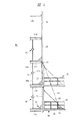
図5は本発明の他の実施の形態である建築機材の搬出入装置を示す断面図であり、図5においては前記実施の形態における部材と共通する部材には同一の符号が付されている。図5においては、昇降台30をガイドレール21,22に沿って上下動させるためにウインチ51が昇降機として昇降台30に取り付けられており、このウインチ51のワイヤ52の先端はガイドポスト31,32に設けられたフック43に止め付けられ、ワイヤ52は上側階のガイドレール21,22に取り付けられた滑車53に掛け渡されている。したがって、図5に示す場合には、昇降台30はこれに取り付けられたウインチ41によって自力で上下動することができる。なお、滑車53を建築物10に取り付けるようにしても良い。
【0034】
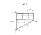
図6は本発明の他の実施の形態である建築機材の搬出入装置の昇降台を示す側面図であり、この昇降台30はガイドポスト31,32の上部側に昇降ステージ33がブラケット34により回動自在に取り付けられており、昇降ステージ33の先端部とガイドポスト31,32の下端部との間には傾斜梁51が取り付けられるようになっている。傾斜梁51はガイドポスト31,32に固定されたブラケット52と昇降ステージ33に固定されたブラケット53と間に連結されており、昇降ステージ33は前述した場合と相違して下側から支持されるようになっている。このようなタイプの昇降台30を建築機材の搬出入装置としても使用することができる。
【0035】
本発明は前記実施の形態に限定されるものではなく、その要旨を逸脱しない範囲で種々変更可能である。たとえば、図示するガイドレール21,22は1階分の高さに相当する長さを有しているが、2階分あるいは3階分の長さとしても良い。図示する上下動案内装置20は2本のガイドレール21,22を有しているが、3本あるいはそれ以上の数のガイドレールを上下動案内装置20に設けるようにしても良い。
【0036】
【発明の効果】
本発明によれば、ガイドレールは締結具により建築物の外側に容易に取り付けることができる。ガイドレールを建築進行に伴う建築物の高さの上昇に応じて連結することにより任意の長さとすることができる。ガイドレールに沿って転動するローラが昇降台に設けられているので、昇降台を任意の位置に停止させることができ、下側階から上側階に建築機材を搬送することができる。下側階で使用済みの建築機材を上側階で再使用する際には、昇降台によって迅速かつ容易に建築機材を搬送することができ、建築に要する期間を短縮することができる。比較的重量が嵩むガイドレールは建築物に取り付けられることになるので、ホイストやクレーンなどの駆動手段によって上下動するのは、軽量な昇降台のみであり、円滑に昇降台を上下動させることができる。
【図面の簡単な説明】
【図1】本発明の一実施の形態である建築機材の搬出入装置を示す正面図である。
【図2】図1におけるII−II線に沿う断面図である。
【図3】上下動案内装置を示す斜視図である。
【図4】昇降台を示す斜視図である。
【図5】本発明の他の実施の形態である建築機材の搬出入装置を示す断面図である。
【図6】本発明の他の実施の形態である建築機材の搬出入装置の昇降台を示す側面図である。
【符号の説明】
10 建築物
11a〜11e ベランダ
20 上下動案内装置
21,22 ガイドレール
23 連結棒材
24a,24b 脚部材
25a,25b 補強棒材
26 締結支柱
26a,26b パイプ部
27 ねじ部
27a ハンドル
28 連結金具
29a 貫通孔
29b ねじ孔
30 昇降台
31,32 ガイドポスト
33 昇降ステージ
34 ブラケット
35 ピン
36 チェーン
37 ブラケット
38 ブラケット
39 手摺り
41 ローラ
42 ワイヤ
43 フック
44 ロックピン
45 取付孔
46 取付孔[0001]
TECHNICAL FIELD OF THE INVENTION
BACKGROUND OF THE
[0002]
[Prior art]
When building middle- or high-rise buildings such as office buildings and condominiums, the upper floors are to be built sequentially from the lower floor, and after the basic skeleton of each floor has been built, Various works such as internal plumbing work, concrete pouring work and interior work are performed. In order to carry out these tasks, it is necessary to carry out construction equipment such as formwork, temporary scaffolding and temporary traveling carts, and construction equipment such as piping to be attached to buildings from outside to each floor. is there.
[0003]
In order to carry the building equipment into the building, an unloading machine is attached to a stand fixed to the building, and the unloading machine lifts the building equipment from the ground to the mounting base, and then loads the building into the building ( For example, see Patent Document 1).
[0004]
[Patent Document 1]
JP 2000-145129 A
[Problems to be solved by the invention]
When the unloader is attached to the frame fixed to the building in this way, the building equipment can be carried from the ground to a predetermined floor of the building, but the building equipment is transported to the upper floor. It is difficult. When performing construction work, for example, after the construction of a part of a predetermined floor is completed, building equipment such as formwork and temporary scaffolds used for construction on that floor is transported to the upper floor, as described above. When a fixed type gantry is used as described above, building equipment cannot be transported from a lower floor to an upper floor. For this reason, when building equipment is re-used from the lower floor to the upper floor, conventionally, it is necessary for the worker to manually transport the building equipment using a scaffold built outside the building. Is not only dangerous, but also time-consuming.
[0006]
An object of the present invention is to make it possible to easily carry building equipment into a building in a short time.
[0007]
It is another object of the present invention to enable building work to be performed quickly in a short period of time.
[0008]
[Means for Solving the Problems]
The loading / unloading device for building equipment according to the present invention is a loading / unloading device for building equipment for loading / unloading building equipment with respect to a building, and is disposed vertically parallel to each other along an outer surface of the building. A plurality of guide rails, a fastener for detachably fastening each of the guide rails to the building, a plurality of guide posts each provided with a roller that rolls along each of the guide rails, and the guide It is provided with an elevating stage attached to a post, comprising: an elevating platform that moves up and down along the guide rail; and a driving unit that drives the elevating platform up and down along the guide rail.
[0009]
The building equipment carrying-in / out apparatus of the present invention is a building equipment carrying-in / out apparatus for carrying building materials in and out of a building, and is disposed in parallel with each other in a vertical direction along an outer surface of the building. A plurality of guide posts each provided with a roller that rolls along the guide rail, an elevating stage attached to the guide post, an elevating table that moves up and down along the guide rail, and stops at a predetermined position In this state, the building equipment is accommodated in the elevator, and the building equipment is transported to the upper floor of the building by the elevator.
[0010]
The building equipment carrying-in / out device of the present invention is a building equipment carrying-in / out device for carrying building materials in and out of a building, and is disposed in parallel with each other in a vertical direction along an outer surface of the building. And a plurality of guide rails for guiding rollers provided on a plurality of guide posts attached to the elevator, and a fastener for detachably fastening each of the guide rails to the building, wherein the elevator Are guided along the guide rails in the up-down direction, and the building equipment is carried into the building with the lift platform stopped at a predetermined position.
[0011]
The loading / unloading device for building equipment according to the present invention includes a lock member that locks the lift table at a predetermined position with respect to the guide rail. The guide rail has a length corresponding to a first floor or a plurality of times of the building, and connects the guide rail according to a height of the building. Further, the construction equipment is carried into the elevator from the ground side while the elevator is stopped at a predetermined position.
[0012]
The loading and unloading device for building equipment of the present invention removes the lowermost guide rail among the plurality of guide rails arranged in a connected state to the building, connects the guide rail to the uppermost side, and connects the plurality of connected rails. Is moved to the upper side of the building. Further, the driving means is an elevator provided on the building or the elevator.
[0013]
BEST MODE FOR CARRYING OUT THE INVENTION
Hereinafter, embodiments of the present invention will be described in detail with reference to the drawings. FIG. 1 is a front view showing a construction equipment carrying-in / out device according to an embodiment of the present invention, and FIG. 2 is a sectional view taken along line II-II in FIG. FIGS. 1 and 2 show a part of a
[0014]
After the construction of the skeleton on the second floor is completed, construction equipment such as formwork and temporary scaffolding is carried into the building in order to perform various operations inside the skeleton. For this purpose, the vertical
[0015]
FIG. 3 is a perspective view showing the vertical
[0016]
When the
[0017]
Each of the guide rails 21 and 22 has a length corresponding to the distance between the verandas adjacent in the vertical direction, and is set to, for example, about 3.8 m to 4 m. Accordingly, when the construction of the skeleton of the upper floor portion is sequentially completed as the construction work progresses, another vertical
[0018]
On the other hand, as shown in FIG. 4, the lift table 30 has two
[0019]
The tip of the elevating
[0020]
Instead of the
[0021]
[0022]
[0023]
In order to transport the
[0024]
By locking the
[0025]
Next, a procedure for performing a building operation using the above-described construction equipment carrying-in / out device will be described. The vertical
[0026]
Next, the
[0027]
When the
[0028]
When the building equipment used for the second-floor building work is used for the third-floor building work, the building equipment such as the formwork used for the second-floor building work is carried into the
[0029]
Next, when the construction work on the second floor is completed, the vertical
[0030]
As building work of the building progresses, by sequentially moving up and down the predetermined number of vertically moving
[0031]
In the case described above, the loading / unloading device is first mounted on the second floor portion, but may be mounted on the third floor portion, and can be mounted from any floor. In addition, three sets of the vertical
[0032]
On the other hand, as a procedure for loading and unloading construction equipment using the loading and unloading device, the guide rails 21 and 22 may be connected from the second or third floor to the top floor. In that case, the building equipment can be directly transported to the
[0033]
FIG. 5 is a cross-sectional view showing a construction equipment carrying-in / out apparatus according to another embodiment of the present invention. In FIG. 5, the same reference numerals are given to members common to the members in the embodiment. . In FIG. 5, a
[0034]
FIG. 6 is a side view showing an elevating platform of a construction equipment carrying-in / out device according to another embodiment of the present invention. It is rotatably mounted, and an
[0035]
The present invention is not limited to the above embodiment, and can be variously modified without departing from the gist thereof. For example, the illustrated
[0036]
【The invention's effect】
According to the present invention, the guide rail can be easily attached to the outside of the building by the fastener. An arbitrary length can be obtained by connecting the guide rails according to the rise of the height of the building as the building progresses. Since the rollers that roll along the guide rails are provided on the elevator, the elevator can be stopped at any position, and the building equipment can be transported from the lower floor to the upper floor. When the building equipment used on the lower floor is reused on the upper floor, the building equipment can be quickly and easily transported by the elevator, and the period required for construction can be shortened. Since relatively heavy guide rails will be attached to the building, only the light lifting platform can be moved up and down by driving means such as a hoist or crane, and it is possible to move the lifting platform up and down smoothly it can.
[Brief description of the drawings]
FIG. 1 is a front view showing a construction equipment carrying-in / out device according to an embodiment of the present invention.
FIG. 2 is a sectional view taken along line II-II in FIG.
FIG. 3 is a perspective view showing a vertical movement guide device.
FIG. 4 is a perspective view showing a lifting platform.
FIG. 5 is a sectional view showing a construction equipment carrying-in / out device according to another embodiment of the present invention.
FIG. 6 is a side view showing an elevating platform of a construction equipment carrying-in / out device according to another embodiment of the present invention.
[Explanation of symbols]
DESCRIPTION OF
Claims (8)
前記建築物の外面に沿って上下方向に相互に平行に配置される複数のガイドレールと、
それぞれの前記ガイドレールを前記建築物に着脱自在に締結する締結具と、
それぞれの前記ガイドレールに沿って転動するローラがそれぞれ設けられた複数のガイドポストと、
前記ガイドポストに取り付けられる昇降ステージを備え、前記ガイドレールに沿って上下方向に移動する昇降台と、
前記昇降台を前記ガイドレールに沿って上下方向に駆動する駆動手段とを有することを特徴とする建築機材の搬出入装置。A building equipment carrying-in / out device for carrying building equipment in and out of a building,
A plurality of guide rails arranged parallel to each other in the vertical direction along the outer surface of the building,
A fastener for detachably fastening each of the guide rails to the building,
A plurality of guide posts each provided with a roller that rolls along each of the guide rails,
An elevating stage that includes an elevating stage attached to the guide post, and that moves vertically along the guide rail,
And a drive unit for driving the lift table in the vertical direction along the guide rail.
前記建築物の外面に沿って上下方向に相互に平行に配置されたガイドレールに沿って転動するローラがそれぞれ設けられた複数のガイドポストと、
前記ガイドポストに取り付けられる昇降ステージを備え、前記ガイドレールに沿って上下方向に移動する昇降台と、
所定位置で停止させた状態のもとで前記昇降台に前記建築機材を収容し、前記昇降台により建築物の上側階に前記建築機材を搬送することを特徴とする建築機材の搬出入装置。A building equipment carrying-in / out device for carrying building equipment in and out of a building,
A plurality of guide posts each provided with a roller that rolls along guide rails arranged in parallel with each other in the vertical direction along the outer surface of the building,
An elevating stage that includes an elevating stage attached to the guide post, and that moves vertically along the guide rail,
A building equipment carrying-in / out device, wherein the building equipment is accommodated in the elevator under a state of being stopped at a predetermined position, and the construction equipment is transported to an upper floor of a building by the elevator.
前記建築物の外面に沿って上下方向に相互に平行となって配置され、昇降台に取り付けられる複数のガイドポストに設けられたローラを案内する複数のガイドレールと、
それぞれの前記ガイドレールを前記建築物に着脱自在に締結する締結具とを有し、
前記昇降台を前記ガイドレールに沿って上下方向に案内するとともに前記昇降台を所定位置で停止させた状態のともで前記建築機材を建築物内に搬入することを特徴とする建築機材の搬出入装置。A building equipment carrying-in / out device for carrying building equipment in and out of a building,
A plurality of guide rails that are arranged parallel to each other in the vertical direction along the outer surface of the building and guide rollers provided on a plurality of guide posts attached to the elevating platform,
Fasteners for detachably fastening each of the guide rails to the building,
Transporting the building equipment into the building while guiding the lifting platform in the vertical direction along the guide rail and stopping the lifting platform at a predetermined position. apparatus.
Priority Applications (1)
| Application Number | Priority Date | Filing Date | Title |
|---|---|---|---|
| JP2002306524A JP2004143677A (en) | 2002-10-22 | 2002-10-22 | Carrying in/out device of construction machine and material |
Applications Claiming Priority (1)
| Application Number | Priority Date | Filing Date | Title |
|---|---|---|---|
| JP2002306524A JP2004143677A (en) | 2002-10-22 | 2002-10-22 | Carrying in/out device of construction machine and material |
Publications (1)
| Publication Number | Publication Date |
|---|---|
| JP2004143677A true JP2004143677A (en) | 2004-05-20 |
Family
ID=32453247
Family Applications (1)
| Application Number | Title | Priority Date | Filing Date |
|---|---|---|---|
| JP2002306524A Pending JP2004143677A (en) | 2002-10-22 | 2002-10-22 | Carrying in/out device of construction machine and material |
Country Status (1)
| Country | Link |
|---|---|
| JP (1) | JP2004143677A (en) |
Cited By (5)
| Publication number | Priority date | Publication date | Assignee | Title |
|---|---|---|---|---|
| JP2008093014A (en) * | 2006-10-06 | 2008-04-24 | Sansei Yusoki Co Ltd | Mobile small elevating stage |
| KR101105255B1 (en) * | 2008-12-12 | 2012-01-17 | 주식회사 콘솔에스더블유씨 | Construction materials lifting system device using guide rail |
| CN107923186A (en) * | 2015-07-27 | 2018-04-17 | 阿尔贝特私人有限公司 | The method of construction platform equipment and installation platform device |
| KR20180105839A (en) * | 2017-03-16 | 2018-10-01 | 주식회사 동신텍 | Slab truss system |
| CN111960033A (en) * | 2020-07-01 | 2020-11-20 | 蒙娜丽莎集团股份有限公司 | High-speed elevator |
-
2002
- 2002-10-22 JP JP2002306524A patent/JP2004143677A/en active Pending
Cited By (6)
| Publication number | Priority date | Publication date | Assignee | Title |
|---|---|---|---|---|
| JP2008093014A (en) * | 2006-10-06 | 2008-04-24 | Sansei Yusoki Co Ltd | Mobile small elevating stage |
| KR101105255B1 (en) * | 2008-12-12 | 2012-01-17 | 주식회사 콘솔에스더블유씨 | Construction materials lifting system device using guide rail |
| CN107923186A (en) * | 2015-07-27 | 2018-04-17 | 阿尔贝特私人有限公司 | The method of construction platform equipment and installation platform device |
| KR20180105839A (en) * | 2017-03-16 | 2018-10-01 | 주식회사 동신텍 | Slab truss system |
| KR102011629B1 (en) | 2017-03-16 | 2019-08-16 | 주식회사 동신텍 | Slab truss system |
| CN111960033A (en) * | 2020-07-01 | 2020-11-20 | 蒙娜丽莎集团股份有限公司 | High-speed elevator |
Similar Documents
| Publication | Publication Date | Title |
|---|---|---|
| US5645395A (en) | Building crane apparatus climbable on building walls | |
| JP6348888B2 (en) | Stair lifting device and method for lifting heavy objects | |
| CA2080079A1 (en) | Self-raising work platform assembly | |
| JP6167025B2 (en) | Stair lifting device and method for lifting heavy objects | |
| JP6270692B2 (en) | Lifting device and lifting method | |
| JP2007205043A (en) | Construction method and dismantling method of scaffolding for high-rise building | |
| JP3579816B2 (en) | Multipurpose stage for building frame | |
| JP3250764B2 (en) | Building exterior curtain wall assembly equipment | |
| JP2004143677A (en) | Carrying in/out device of construction machine and material | |
| KR100583785B1 (en) | Construction-material lift being installed at the outside of the construction-structure | |
| JP6621732B2 (en) | Work floor equipment | |
| JP5356091B2 (en) | Crane girder exchanging method and crane girder exchanging apparatus | |
| CN116568627A (en) | Point loading lifting fork for lifting an upright form | |
| JP3220397B2 (en) | Elevating scaffold | |
| KR101031313B1 (en) | The construction workbench for an elevator infrastructure establishment | |
| KR101800622B1 (en) | Multi-type lifting scaffold | |
| JP2017071488A (en) | Device and method for stair lifting of heavy load | |
| JP5150313B2 (en) | Three-dimensional parking device in void and its construction method | |
| JP2008214062A (en) | Lifting device and structural material mounting method | |
| JP2006144402A (en) | Constructing method of scaffolding for high-rise building and dismantling method | |
| KR101733948B1 (en) | Both sides supporting type loading deck for landing of building materials | |
| JP4011722B2 (en) | Hanging stairs | |
| JP4784167B2 (en) | Scaffolding device for elevator installation work | |
| KR20210000005A (en) | Lift Worktable For Railway | |
| KR200356598Y1 (en) | Construction-material lift being installed at the outside of the construction-structure |
Legal Events
| Date | Code | Title | Description |
|---|---|---|---|
| A621 | Written request for application examination |
Free format text: JAPANESE INTERMEDIATE CODE: A621 Effective date: 20050803 |
|
| A977 | Report on retrieval |
Free format text: JAPANESE INTERMEDIATE CODE: A971007 Effective date: 20070910 |
|
| A131 | Notification of reasons for refusal |
Free format text: JAPANESE INTERMEDIATE CODE: A131 Effective date: 20070918 |
|
| A02 | Decision of refusal |
Effective date: 20080205 Free format text: JAPANESE INTERMEDIATE CODE: A02 |