JP2004142434A - Ink tank and recorder - Google Patents
Ink tank and recorder Download PDFInfo
- Publication number
- JP2004142434A JP2004142434A JP2003322986A JP2003322986A JP2004142434A JP 2004142434 A JP2004142434 A JP 2004142434A JP 2003322986 A JP2003322986 A JP 2003322986A JP 2003322986 A JP2003322986 A JP 2003322986A JP 2004142434 A JP2004142434 A JP 2004142434A
- Authority
- JP
- Japan
- Prior art keywords
- ink tank
- ink
- cartridge
- sensor
- tank
- Prior art date
- Legal status (The legal status is an assumption and is not a legal conclusion. Google has not performed a legal analysis and makes no representation as to the accuracy of the status listed.)
- Pending
Links
Images

Abstract
Description
本発明は、インクを吐出して記録媒体に記録を行うインクジェット方式の記録装置およびインクタンクに関し、具体的には記録装置に対して着脱自在なインクタンクの有無検知に関する。 The present invention relates to an ink jet recording apparatus and an ink tank that perform recording on a recording medium by discharging ink, and more specifically, to the detection of the presence or absence of an ink tank that is detachable from the recording apparatus.
なお、本発明において、インクタンクの「側壁近傍」の「近傍」とは、インクタンクの下面のインク供給口付近が撓んでも、この撓みの影響が及びにくい、すなわち、押し当て部による機械的スイッチの変位が所定のとおりに行うことができないような撓み量を生じない領域を指す。 In the present invention, the term “near” the “near the side wall” of the ink tank means that even if the vicinity of the ink supply port on the lower surface of the ink tank is bent, the influence of the bending is hard to reach. It refers to a region where the amount of bending does not occur such that the displacement of the switch cannot be performed as predetermined.
従来、紙、布、プラスチックシート、OHP用シート等の記録媒体(以下、単に「記録紙」ともいう)に対して記録を行う記録装置は、種々の記録方式、例えばワイヤードット方式、感熱方式、熱転写方式、インクジェット方式による記録ヘッドを搭載可能な形態として提案されている。 2. Description of the Related Art Conventionally, a recording apparatus that performs recording on a recording medium (hereinafter, also simply referred to as “recording paper”) such as paper, cloth, plastic sheet, OHP sheet, and the like, employs various recording methods such as a wire dot method, a heat-sensitive method, It has been proposed as a form in which a recording head by a thermal transfer method or an ink jet method can be mounted.
そのような記録装置のなかで、インクジェット記録装置は、ランニングコストが安く、装置の小型化も可能であり、さらに、複数色のインクを用いてカラー画像記録に対応することも容易である。なかでも、記録紙の幅方向に多数の吐出口を配列したラインタイプの記録ヘッドを使用したライン型の記録装置は、記録の一層の高速化が可能である。 か で Among such recording apparatuses, the inkjet recording apparatus has a low running cost, can be downsized, and can easily cope with color image recording using inks of a plurality of colors. Above all, a line type recording apparatus using a line type recording head in which a large number of ejection openings are arranged in the width direction of the recording paper can further increase the recording speed.
上記の理由から、インクジェット記録装置は、情報処理システムの出力手段、例えば複写機、ファクシミリ、電子タイプライタ、ワードプロセッサ、ワークステーション等の出力端末としてのプリンタ、あるいはパーソナルコンピュータ、ホストコンピュータ、光ディスク装置、ビデオ装置等に具備されるハンディまたはポータブルプリンタとして利用され、かつ商品化されている。 For the above reasons, the inkjet recording apparatus is an output means of an information processing system, for example, a printer as an output terminal such as a copying machine, a facsimile, an electronic typewriter, a word processor, a workstation, or a personal computer, a host computer, an optical disk device, and a video. It is used as a handy or portable printer provided in an apparatus or the like, and is commercialized.
このような記録ヘッドにインクを供給するインクタンクは、インク吸収体と、このインク吸収体を収納する容器と、これを封止する蓋部材とで概略構成される。 イ ン ク An ink tank for supplying ink to such a recording head is schematically composed of an ink absorber, a container for accommodating the ink absorber, and a lid member for sealing the ink absorber.
また、上記記録ヘッドは、上記インクタンクと一体に構成されたインクタンク一体型のものと、インクタンクが着脱自在に構成されたインクタンク交換型のものとがある。 The recording head is classified into an ink tank integrated type integrally formed with the ink tank, and an ink tank exchange type integrated with the ink tank detachable.
近年、記録ヘッドの信頼性の向上により、また、ランニングコストが低く抑えられることから、インクタンク交換型の記録ヘッドを用いたインクジェット記録装置が市場で広く受け入れられており、特に、カラープリントへ対応するために、複数のインクタンク(例えば、ブラックとカラー(シアン、マゼンタ、イエロー)の2つのインクタンク、またはブラック、シアン、マゼンタ、イエローの4つのインクタンク等)がそれぞれ交換可能に搭載されたインクジェット記録装置が市場で受け入れられている。 In recent years, ink jet recording apparatuses using ink tank replaceable recording heads have been widely accepted in the market due to the improvement of the reliability of the recording heads and the reduction of running cost, especially for color printing. In order to accomplish this, a plurality of ink tanks (for example, two ink tanks of black and color (cyan, magenta, yellow) or four ink tanks of black, cyan, magenta, yellow, etc.) are mounted in a replaceable manner. Ink jet recording devices have been accepted in the market.
このようなインクタンク交換型の記録ヘッドの場合、インクタンクから記録ヘッドへと確実にインクを供給するための、インクタンクと記録ヘッドとの位置決めは、記録品位に係わる重要な事項である。そのため、小型でありながら、より簡単な操作、あるいはより簡単な機構で、着脱時の不都合がなく、しかも位置決め精度を低下させることのない構成を得ることは重要である。 In the case of such an ink tank exchange type recording head, the positioning between the ink tank and the recording head for ensuring the supply of ink from the ink tank to the recording head is an important matter relating to the recording quality. Therefore, it is important to obtain a configuration that is small in size, has a simpler operation, or has a simpler mechanism, does not cause any inconvenience at the time of attachment and detachment, and does not reduce the positioning accuracy.
その手段のひとつとしては、特許文献1に、小型インクジェット記録装置に用いられるインクタンクとして、インクジェット記録ヘッドを備えたホルダに対して着脱自在にされるインクタンクにおいて、インク供給口を底面に備え、この底面に隣接する一端面にインクタンクホルダーに形成された抜け止め孔に嵌合する爪状突起が設けられるとともに、他端面に、インクタンクホルダーに形成された係合孔に結合するラッチ爪が設けられたラッチレバーが弾性的に支持されて設けられている構成についても開示しており、位置決め精度を低下させずに簡単な操作・機構でインクタンクの着脱を行える構成として、広く採用されている。
As one of the means, in
また、持ち運びが可能なホータブルプリンタなどでは、プリンタを非常に小さく構成させることが要求されるため、当然インクタンクも非常に小さく構成する必要がある。 ホ ー In addition, in a portable printer or the like, it is required to make the printer very small, so that the ink tank also needs to be made very small.
しかし、インクタンクを小さくすると内部容積が小さくなり、収納されるインクの容量も小さくなるため、ひとつのインクタンクで印刷できる枚数が減り、インクタンクの交換頻度が高くなる。また、インクタンクを小さくしたことによるインクの残量不足により生じるインクかすれといった印刷不良を防止するためにはインク残量検知を行う必要がある。 However, when the ink tank is made smaller, the internal volume becomes smaller, and the capacity of the stored ink becomes smaller, so that the number of sheets that can be printed with one ink tank decreases, and the frequency of ink tank replacement increases. Further, it is necessary to detect the remaining amount of ink in order to prevent printing defects such as blurred ink caused by insufficient amount of ink due to the reduced size of the ink tank.
インク残量検知方式にはインク残量を直接測定する方式と、使用したインク量をカウントするいわゆるドットカウント方式があり、小さなインクタンクの内部容量をできる限り確保して使用可能なインク量を多くするためにはインクタンク内部に特別な機構の必要ないドットカウント方式が好ましい。 The remaining ink level detection method includes a method of directly measuring the remaining amount of ink and a so-called dot counting method that counts the amount of used ink. For this purpose, a dot counting method that does not require a special mechanism inside the ink tank is preferable.
また、ドットカウント方式の精度を上げるためにはインクタンクが交換されたかどうかを判別するための検知手段が必要であり、その方式としてはインクタンクに記憶手段を有し、プリンタと電気的な接続を行うことで検知を行う電気的方式と、プリンタに設けられた機械スイッチによってインクタンクの交換を検知する機械的方式が考えられるが、これも前述と同様に、小さなインクタンクの内部容量をできる限り確保して使用可能なインク量を多くするためにはインクタンクに特別な記憶手段の必要ない機械的方式が好ましい。
しかしながら、プリンタと着脱可能なインクジェットカートリッジに対して交換可能なインクタンクを搭載する際には、各々の装着誤差が影響して前述のインクタンク検知手段とインクタンクとの位置精度をだすことが難しい。 However, when a replaceable ink tank is mounted on an ink-jet cartridge that is detachable from the printer, it is difficult to obtain the positional accuracy between the above-described ink tank detection means and the ink tank due to mounting errors. .
一方、プリンタを小さく構成するためには、プリンタに設けられたインクタンク検知手段と、インクタンクのインクタンク検知手段との当接部の位置精度を上げる必要がある。 On the other hand, in order to reduce the size of the printer, it is necessary to increase the positional accuracy of the ink tank detecting means provided in the printer and the contact portion of the ink tank with the ink tank detecting means.
そこで、本発明は上記課題に鑑み、プリンタに設けられた機械式のインクタンク検知手段を所望の変位量だけ変位させる精度を有するインクタンクを提供することを目的とする。 Accordingly, in view of the above problems, it is an object of the present invention to provide an ink tank having the accuracy of displacing a mechanical ink tank detecting means provided in a printer by a desired displacement amount.
上記目的を達成するために本発明のインクタンクは、インクタンクを着脱自在に搭載可能な記録ヘッドを有するカートリッジと、該インクタンクがカートリッジに装着されたことを変位により検知する機械的スイッチと、を備えたインクジェット記録装置に対して着脱自在なインクタンクであって、内部に収納されたインクを記録ヘッドに供給するためのインク供給口を備え、インクタンクの使用状態で底となる下面と、カートリッジに対してインクタンクを装着するための係合部を有する側面と、下面に対して窪んで形成され、一端が側面に対して開放されている段差部と、を備え、段差部の側面の近傍に、機械的スイッチを変位させる凸状の押し当て部を備えていることを特徴とする。 In order to achieve the above object, an ink tank according to the present invention includes a cartridge having a recording head capable of detachably mounting the ink tank, a mechanical switch that detects that the ink tank is mounted on the cartridge by displacement, An ink tank that is detachable with respect to an ink jet recording apparatus having an ink supply port for supplying ink stored inside to a recording head, and a bottom surface that is a bottom in the use state of the ink tank, A side surface having an engaging portion for mounting the ink tank to the cartridge; and a step portion formed to be concave with respect to the lower surface and having one end open to the side surface. A convex pressing portion for displacing the mechanical switch is provided in the vicinity.
上述の通り構成された本発明のインクタンクは、インクタンクがカートリッジに装着されたことを変位することで検知する機械的スイッチを変位させる凸状の押し当て部(以下、突起)が、インクタンクの下面の、係合部が設けられた側面近傍に設けられている。機械的スイッチに突起が当接する際、シール部材の反力を受けて下面が撓んでも、側面近傍に突起が設けられているため突起にこの撓みの影響が及びにくいものとなっている。また、突起は、係合部の近傍に設けられているので、インクタンクを装着した際の位置精度を向上させて、機械的スイッチを確実に動作させることができる。本発明のインクタンクでは、さらに、突起が下面に対して窪んで形成された段差部に設けられていることで、突起部近傍の筐体の強度を向上させ、インクタンクを装着した際の位置精度を向上させて、機械的スイッチを確実に動作させることができる。 The ink tank of the present invention configured as described above has a convex pressing portion (hereinafter referred to as a protrusion) for displacing a mechanical switch that detects by displacing that the ink tank is mounted on the cartridge. Is provided in the vicinity of the side surface on which the engaging portion is provided on the lower surface of the. When the projection comes into contact with the mechanical switch, even if the lower surface bends due to the reaction force of the seal member, the projection is provided near the side surface, so that the influence of the deflection is less likely to be exerted on the projection. In addition, since the protrusion is provided near the engaging portion, the positional accuracy when the ink tank is mounted can be improved, and the mechanical switch can be reliably operated. In the ink tank of the present invention, the protrusion is further provided on the stepped portion formed to be depressed with respect to the lower surface, so that the strength of the housing near the protrusion is improved, and the position when the ink tank is mounted is improved. The accuracy can be improved and the mechanical switch can be operated reliably.
さらに、本発明のインクタンクは、段差部に設けられた突起の高さが、段差部から下面までの高さ以下であるものであってもよい。このように、段差部から突起が露出していない構成とすることで、インクタンクをカートリッジに装着する際に、誤ってインクタンクを落下させても、突起に傷をつけにくくすることができ、よって、より信頼性を高めることができる。 Further, in the ink tank of the present invention, the height of the projection provided on the step portion may be equal to or less than the height from the step portion to the lower surface. In this way, the protrusion is not exposed from the step, so that when the ink tank is mounted on the cartridge, even if the ink tank is accidentally dropped, the protrusion can be hardly damaged. Therefore, the reliability can be further improved.
本発明の記録装置は、本発明のインクタンクを着脱自在に装着する前記カートリッジを保持し、往復走査可能に設けられた保持手段を有する記録装置であって、インクを吐出する電気信号に基づき、前記カートリッジに設けられた前記記録ヘッドからインクを吐出して被記録媒体に記録を行うことを特徴とする。 The recording apparatus of the present invention is a recording apparatus that holds the cartridge in which the ink tank of the present invention is detachably mounted, and has a holding unit provided so as to be capable of reciprocating scanning, based on an electric signal for discharging ink, The recording is performed on a recording medium by discharging ink from the recording head provided in the cartridge.
すなわち、本発明のインクタンクを用いる本発明の記録装置は、インクタンクの装着を機械的に検知する機械的スイッチを備えた保持手段を有する。このため、本発明の記録装置は、インクタンクに電気的な記憶手段等が必要ない分、小さなインクタンクの内部容量をできる限り確保して使用可能なインク量を多くしたインクタンクを用いることができ、小型化を図ることができる。さらには、本発明のインクタンクを用いるため、記録装置を小さく構成した場合に必要となる、インクタンク検知手段と、インクタンクの突起との位置精度の向上も図ることができる。 That is, the recording apparatus of the present invention using the ink tank of the present invention has a holding unit provided with a mechanical switch for mechanically detecting the mounting of the ink tank. For this reason, the recording apparatus of the present invention uses an ink tank in which the internal capacity of a small ink tank is ensured as much as possible and the amount of usable ink is increased, since the ink tank does not require an electric storage means or the like. And downsizing can be achieved. Furthermore, since the ink tank of the present invention is used, it is possible to improve the positional accuracy between the ink tank detecting means and the projection of the ink tank, which is required when the recording apparatus is made small.
また、本発明の記録装置は機械的スイッチが保持手段の側壁の近傍に設けられているものであってもよい。このように、側壁近傍に機械的スイッチを設けることで、撓みによる影響を受けにくくすることができるので、機械的スイッチと、インクタンクの突起との位置精度のさらなる向上を図ることができる。 The recording apparatus of the present invention may be configured such that the mechanical switch is provided near the side wall of the holding means. By providing the mechanical switch in the vicinity of the side wall as described above, the influence of the bending can be reduced, so that the positional accuracy between the mechanical switch and the protrusion of the ink tank can be further improved.
本発明によれば、機械的スイッチを変位させる凸状の押し当て部が、インクタンクの下面の、係合部が設けられた側面近傍に設けられているため、下面が撓んでも突起にこの撓みの影響が及びにくいとともに、インクタンクを装着した際の位置精度が向上するため、機械的スイッチを確実に動作させることができる。 According to the present invention, since the convex pressing portion for displacing the mechanical switch is provided on the lower surface of the ink tank near the side surface on which the engaging portion is provided, even if the lower surface is bent, the protrusion is formed on the projection. Since the influence of the bending is less likely to occur and the positional accuracy when the ink tank is mounted is improved, the mechanical switch can be reliably operated.
また、突起が、段差部に設けられていることでインクタンクをカートリッジに装着する際に、誤ってインクタンクを落下させても、突起に傷をつけにくくすることができ、信頼性を高めることができる。 In addition, since the projection is provided on the stepped part, even if the ink tank is accidentally dropped when the ink tank is mounted on the cartridge, it is possible to prevent the projection from being damaged and improve reliability. Can be.
次に、本発明の実施の形態について図面を参照して説明する。
(第1の実施形態)
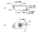
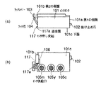
図1は、本実施形態のインクジェットカートリッジの模式図であり、(a)は側面図であり、(b)は下面図である。
Next, embodiments of the present invention will be described with reference to the drawings.
(1st Embodiment)
FIGS. 1A and 1B are schematic diagrams of an ink jet cartridge according to the present embodiment. FIG. 1A is a side view, and FIG. 1B is a bottom view.
内部にインクを収納するインクタンク1は、第1の側面1aには、後述するインクジェットカートリッジ11に形成されている抜け止め穴12と係合する第1係合部である抜け止め爪2が設けられており、第1の側面1aの反対側の面である第2の側面1bに、第2係合部であるラッチ爪4を有するラッチレバー3が弾性的に設けられている。また、インクタンク1の下面1cにはインクジェットカートリッジ11にインクを供給するためのインク供給口5が設けられている。下面1cはインクタンク1の使用状態で底となり、この下面1cの一部には、下面1cから深さhの段差6が形成されている。この段差6には後述するキャリッジ21に設けられているインクタンクセンサ22を当接面7aにより押す凸状の押しあて部であるセンサ押し突起7が設けられている。センサ押し突起7の高さ、すなわち、当接面7aまでの高さは段差6の深さh以下に設定されている。また、インクタンク1の上面には、インクタンク1内と大気を連通させるための不図示の大気連通口が形成されている。
An
次に、本実施形態のインクタンク1をインクジェットカートリッジ11に装着する操作の過程について説明する。
Next, a process of an operation of mounting the
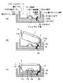
図2はインクタンクを記録装置のキャリッジに装着されたインクジェットカートリッジに装着する操作の過程を示す断面の模式図であり、(a)はインクタンクが装着されていない状態、(b)はインクタンクを装着する途中の状態、(c)はインクタンクの装着が完了した状態をそれぞれ示すものである。 2A and 2B are schematic cross-sectional views showing a process of mounting an ink tank on an ink jet cartridge mounted on a carriage of a recording apparatus. FIG. 2A is a state in which no ink tank is mounted, and FIG. (C) shows a state in which the mounting of the ink tank is completed.
インクジェットカートリッジ11は、不図示の記録装置に往復走査可能に設けられたキャリッジ21に搭載されている。インクジェットカートリッジ11は、第1のカートリッジ側面11a、第2のカートリッジ側面11bおよびカートリッジ下面11cにより概ね構成されており、上方にはインクタンク1を装着可能なように開口11eが形成されている。
The inkjet cartridge 11 is mounted on a carriage 21 which is provided in a recording device (not shown) so as to be capable of reciprocating scanning. The ink jet cartridge 11 is generally constituted by a first
第1のカートリッジ側面11aには、インクタンク1の抜け止め爪2が係合する抜け止め孔12が形成されており、第2のカートリッジ側面11bには、インクタンク1のラッチ爪4が係合する抜け止め孔13が形成されている。
A retaining
インクジェットカートリッジ11のカートリッジ下面11cには、インク連通管14が突出して設けられており、インクタンク1のインク供給口5が当接することで、インクタンク1内のインクがインク連通管14を介してカートリッジ下面11cに設けられ、記録装置からの電気信号に基づきインクを吐出する不図示の記録ヘッドに供給される。このインク連通管14の周囲には、インクの漏洩を防止するためのOリング等のシール部材15が取り付けられている。また、カートリッジ下面11cには、インクタンク1が搭載されたか否かを検知するための機械式スイッチのインクタンクセンサ22の先端部22aが突出するセンサ用穴11dが形成されている。キャリッジ21に設けられたインクタンクセンサ22は、可倒式のセンサであり、後述するように、インクタンク1のセンサ押し突起7がこのインクタンクセンサ22を押し倒して変位させることでインクタンク1がインクジェットカートリッジ11に装着されたことを検知するものである。よって、センサ用穴11dは、インクタンクセンサ22が傾倒した際にも干渉しない大きさのものとなっている。なお、インクタンクセンサ22は、キャリッジ21の側壁21aの近傍に設けられていることで、図2に示すように、インクジェットカートリッジ11の第1のカートリッジ側面11aおよびインクタンク1の第1の側面1aの近傍に位置することとなる。
An
インクタンク1は、以上のような構成のインクジェットカートリッジ11の開口11eに、図2(b)に示すように、第1の側面1a側から傾けて挿入される。すなわち、インクタンク1を装着する際には、まず、インクタンク1の抜け止め爪2が、抜け止め穴12が形成された第1のカートリッジ側面11aに向かうように下側にして斜めにしてインクジェットカートリッジ11の開口11e上に置き、抜け止め爪2を抜け止め穴12に係合させる。このときセンサ押し突起7がインクタンクセンサ22と当接する。
(2) The
インクタンク1のラッチレバー3は、第2のカートリッジ側面11bの上端部に当接した状態になっている。インクタンク1は、この状態から下向きに押し込こまれることで、ラッチレバー3を撓ませながら、また、センサ押し突起7がインクタンクセンサ22を徐々に矢印A方向に倒しながら、インクジェットカートリッジ11に挿入されていく。このとき、ラッチレバー3の反力により抜け止め爪2が抜け止め穴12に押しつけられるため、抜け止め爪2と抜け止め穴12との係合が解除されてしまうことはない。
ラ ッ チ The latch lever 3 of the
さらに、インクタンク1を下向きに押し込むことで、図2(c)に示すように、インクタンク1のインク供給口5とインクジェットカートリッジ11のインク連通管14とが当接するとともにラッチ爪4がラッチ抜け止め穴13に係合してインクタンク1のインクジェットカートリッジ11への装着が完了する。なお、図2(c)は、インク供給口5とインク連通管14との連通を示すため、インクタンク1は、インク供給口近傍を破断して示している。インク連通管14の周囲に取り付けられたシール部材15は、インクタンク1の下面1cとカートリッジ下面11cとに挟み込まれることでインク供給口5とインク連通管14との連通部をシールする。この際、インクタンク1の下面1cのインク供給口5周辺、すなわち、下面1c中央部近傍は、シール部材15の反力により若干撓むこととなるが、センサ押し突起7は、第1の側面1a近傍に形成されていることで、インクタンク1の下面1c中央部近傍の撓みによる影響を受けずに確実にインクタンクセンサ22を動作させることができる。
Further, by pushing the
また、本実施形態のインクタンク1のセンサ押し突起7は、抜け止め爪2の近傍に設けられているので、インクタンク1をインクジェットカートリッジ11に装着した際の位置精度を向上させて、インクタンクセンサ22を確実に動作させることができる。
Further, since the sensor pressing projection 7 of the
さらに、本実施形態のインクタンク1のセンサ押し突起7は、下面1cから窪んで形成された段差6に設けられており、かつ、その高さは段差6の深さh以下であるため、センサ押し突起7のインクタンクセンサ22への当接面7aがインクタンク1の下面1cから露出していない。よって、インクタンク1をインクジェットカートリッジ11に装着する際に、誤ってインクタンク1を落下させても、センサ押し突起7のインクタンクセンサ22との当接面7aに傷をつけにくくすることができ、よって、より信頼性を高めることができる。
Further, since the sensor pressing projection 7 of the
また段差部6を設けることで、その部分のインクタンク底面の強度を高めることができる。温度差による環境変化や、インクタンクのカートリッジへの装着等による力に対しても変形が防止される。その段差部6にセンサ押し突起7を設けることで位置精度を向上させることができ、確実なセンサの動作が保証される。なお、この段差部6は、その一端が第1の側面1aに対して開放された開放部6aが形成されているものであってもよい。
By providing the stepped portion 6, the strength of the bottom surface of the ink tank at that portion can be increased. Deformation is also prevented by an environmental change due to a temperature difference or a force caused by mounting the ink tank to the cartridge. By providing the sensor pressing projection 7 on the step portion 6, the positional accuracy can be improved, and reliable operation of the sensor is guaranteed. The step portion 6 may be formed with an
また、インクタンクセンサ22もキャリッジ21の側壁21aの近傍に設けられていることで、キャリッジ21の下面の撓みによる影響を受けにくくすることができるので、機械的スイッチと、インクタンクの突起との位置精度のさらなる向上を図ることができる。
Further, since the
さらに、インクジェットカートリッジ11の保持手段であるキャリッジ21は、インクタンク1の装着を機械的に検知するインクタンクセンサ22を備えた構成となっている。このため、本発明の記録装置は、インクタンク1に電気的な記憶手段等が必要ない分、小さなインクタンク1の内部容量をできる限り確保して使用可能なインク量を多くしたインクタンク1を用いることができ、小型化を図ることができる。さらには、本発明の記録装置は、本発明のインクタンク1を用いるため、記録装置を小さく構成した場合に必要となる、インクタンクセンサ22と、インクタンク1のセンサ押し突起7との位置精度の向上も図ることができる。
(第2の実施形態)
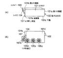
図3は本発明の第2の実施形態のインクタンクを示す模式図であり、(a)は側面図、(b)は下面図である。また、図4は、第1の実施形態と同様にインクタンクを記録装置のキャリッジに装着されたインクジェットカートリッジに装着する操作の過程を示す断面の模式図であり、(a)はインクタンクが装着されていない状態、(b)はインクタンクを装着する途中の状態、(c)はインクタンクの装着が完了した状態をそれぞれ示す。
Further, the carriage 21 serving as a holding unit of the ink jet cartridge 11 has an
(Second embodiment)
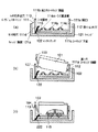
3A and 3B are schematic views showing an ink tank according to a second embodiment of the present invention, wherein FIG. 3A is a side view, and FIG. 3B is a bottom view. FIGS. 4A and 4B are schematic cross-sectional views showing a process of mounting an ink tank on an ink jet cartridge mounted on a carriage of a recording apparatus, similarly to the first embodiment. FIG. (B) shows a state in which the ink tank is being mounted, and (c) shows a state in which the mounting of the ink tank is completed.
本実施形態のインクタンク101は、基本的な構成は第1の実施形態と同じであるが、その内部が3室に区切られており、各々にシアン、マゼンタ、イエローの3色のインクが収納されており、各色に対応して、インク供給口105c、105m、105yが下面101cに設けられている点が異なる。また、第1の実施形態では、抜け止め爪2が設けられている第1の側面1a側の下面1cに段差6が形成され、この段差6にセンサ押し突起7が設けられた構成を示したが、本実施形態の場合、ラッチレバー3が設けられた第2の側面101b側の下面101cに段差106が形成され、この段差106にセンサ押し突起107が設けられている点でも異なる。また、このセンサ押し突起107は、下面101c方向には突出していないが、第2の側面101b方向には突出して形成されている。すなわち、センサ押し突起107のインクタンクセンサ122を押す当接面107aは、図3(b)に示すように、第2の側面101bの真下に位置している。
The
本実施形態のインクジェットカートリッジ111も、不図示の記録装置に往復走査可能に設けられたキャリッジ121に搭載されており、インクジェットカートリッジ111およびキャリッジ121の基本的な構成は、ともに第1の実施形態で説明したインクジェットカートリッジ11およびキャリッジ12と同様であるが、インクジェットカートリッジ111のカートリッジ下面111cには、インク供給口105c、105m、105yに対応したインク連通管104c、104m、104yが突出して設けられている点、ラッチ系係合穴113が形成されている第2のカートリッジ側面111bにセンサ用穴111dが形成されている点、およびインクタンクセンサ122が、キャリッジ121の、第2のカートリッジ側面111b側の側壁であるキャリッジ121a側に設けられている点が異なる。
The ink jet cartridge 111 of the present embodiment is also mounted on a carriage 121 provided in a recording apparatus (not shown) so as to be capable of reciprocating scanning. The basic configurations of the ink jet cartridge 111 and the carriage 121 are the same as those of the first embodiment. It is the same as the ink jet cartridge 11 and the
次に、本実施形態のインクタンク101をインクジェットカートリッジ111に装着する操作の過程について図4(b)、(c)を用いて説明する。
Next, the process of mounting the
本実施形態の場合も、第1の実施形態で説明した装着手順と概ね同様である。 場合 In the case of this embodiment as well, the mounting procedure described in the first embodiment is substantially the same.
まず、インクタンク101の抜け止め爪102が、抜け止め穴112が形成された第1のカートリッジ側面111aに向かうように下側にして斜めにしてインクジェットカートリッジ111の開口111e上に置き、抜け止め爪102を抜け止め穴112に係合させる。このときセンサ押し突起107がインクタンクセンサ122と当接する。
First, the retaining
インクタンク101は、下向きに押し込まれることで、ラッチレバー103を撓ませながら、また、センサ押し突起107がインクタンクセンサ122を徐々に押し倒しながら、インクジェットカートリッジ111に挿入されていく。このとき、ラッチレバー103の反力により抜け止め爪102が抜け止め穴112に押しつけられるため、抜け止め爪102と抜け止め穴112との係合が解除されてしまうことはない。
(4) The
さらに、インクタンク101を下向きに押し込むことで、図4(c)に示すように、インクタンク101のインク供給口105c、105m、105yとインクジェットカートリッジ11のインク連通管104c、104m、104yとが当接するとともにラッチ爪104がラッチ抜け止め穴113に係合してインクタンク101のインクジェットカートリッジ11への装着が完了する。
Further, by pushing the
下面101cは、シール部材115をインクタンク101の下面101cとカートリッジ下面11cとに挟み込むことで、シール部材115の反力により若干撓む。特に、インク供給口105mからセンサ押し突起107までの距離は、第1の実施形態に示したインク供給口5からセンサ押し突起7までの距離に比べて短いことで撓みの影響は第1の実施形態の場合に比べると大きいものの、本実施形態の場合、センサ押し突起107の当接面107aは、第2の側面101bの真下に位置しているため、シール部材115の反力がかかる方向へのセンサ押し突起107の変位は極めて小さい。よって、本実施形態の場合も、インクタンク101の下面101cの撓みによる影響を受けずに確実にインクタンクセンサ122を動作させることができる。
The
さらに、本実施形態においては、ラッチレバー103の下にセンサ押し突起107を設けているので、ラッチレバー103下の空間を有効に活用することができる。これによってインクタンク101の内部容積を圧迫することがなくなるので、より多くのインク容量を確保することができる。また、インクタンクセンサ122をキャリッジ121の外壁であるキャリッジ側面121aの近傍に配置することができるので、組立精度が向上し、タンク押し突起107とインクタンクセンサ122との位置精度を向上させることができる。
Further, in the present embodiment, since the
なお、タンク押し突起は、図7の符号117に示すようにリブ状のものでもよく、また、インクタンクセンサと接触しない部分については、段差部からはみ出して設けられていてもよい。このようにタンク押し突起117をリブ状にすることで、タンク押し突起の強度を高め、接触面117aが、インクタンクの装着時に確実にインクタンクセンサを動作させることができる。
Note that the tank pressing projection may be a rib-shaped one as shown by
なお、前述の第1の実施形態では、センサ押し突起7が段差部6内に設けられているのに対し、本実施形態では、センサ押し突起は、その基部(あるいは基部の一部)が段差部内に設けられているものの、突起自体はインクタンクの側壁に対して突出するように設けられている。 In the above-described first embodiment, the sensor pressing protrusion 7 is provided in the stepped portion 6, whereas in the present embodiment, the sensor pressing protrusion has a base (or a part of the base) having a stepped portion. Although provided in the section, the projection itself is provided so as to protrude from the side wall of the ink tank.
本願発明において、インクタンクの側壁近傍の近傍とは、これらの実施形態を全て含むものであり、このように段差部内に少なくとも突起部の一部を有することで、インクタンクをインクジェットカートリッジに装着した際に、機械的スイッチの変位が確実に行われる。 In the present invention, the term "near the vicinity of the side wall of the ink tank" includes all of these embodiments. By having at least a part of the protrusion in the stepped portion as described above, the ink tank is mounted on the inkjet cartridge. At this time, the mechanical switch is reliably displaced.
しかしながら落下などによる損傷を防止できること、段差からの突起の高さを高く出来ること、インクジェットカートリッジへの装着によってインクタンク底面の供給口付近が撓んだとしてもその影響を受けずに確実に機械的スイッチの変位を行えること、を全て同時に満たすためには、前述の第1実施形態のように、突起部が段差部内に設けられており、その高さが段差部の深さ以下になっている方が、より望ましい。
(第3の実施形態)
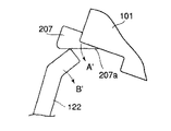
図5は本発明の第3の実施形態のインクタンクを示す模式図であり、(a)は側面図、(b)はラッチレバー3の下側に設けられたセンサ押し突起部の各図である。センサ押し突起の底面であるインクタンクセンサとの当接面が斜めに構成されている以外は第2の実施形態と同じであるため、同様の部分に関しては説明を省略する。また、説明に用いる符号も、第2の実施形態と異なる部位以外は同じ符号を用いるものとする。
However, it can prevent damage due to dropping, etc., can increase the height of the protrusion from the step, and even if the vicinity of the supply port on the bottom of the ink tank is bent by mounting on the ink jet cartridge, In order to simultaneously satisfy the requirement that the switch can be displaced, as in the first embodiment described above, the protrusion is provided in the step, and the height is less than the depth of the step. Is more desirable.
(Third embodiment)
FIGS. 5A and 5B are schematic views showing an ink tank according to a third embodiment of the present invention, wherein FIG. 5A is a side view, and FIG. 5B is a view of a sensor pressing projection provided on the lower side of the latch lever 3. is there. The second embodiment is the same as the second embodiment except that the contact surface with the ink tank sensor, which is the bottom surface of the sensor pushing protrusion, is formed obliquely. Also, the same reference numerals are used for the description except for the parts different from those in the second embodiment.
本実施形態のセンサ押し突起207は、当接面207aが、インクタンク101の下面101cと平行な段差106の段差面106aに対して角度αの傾斜をもって形成されている。
The
図6は、インクタンクが装着される過程で、センサ押し突起がインクタンクセンサと当接し始めた状態を示す模式図であり、矢印A´はセンサ押し突起の移動方向を示し、矢印B´はインクタンクセンサの移動方向を示す。 FIG. 6 is a schematic diagram showing a state in which the sensor pressing protrusion has started to abut on the ink tank sensor in the process of mounting the ink tank. An arrow A ′ indicates the moving direction of the sensor pressing protrusion, and an arrow B ′ indicates The direction of movement of the ink tank sensor is shown.
センサ押し突起207の当接面207aを傾斜面とすることで、センサ押し突起207とインクタンクセンサ122を概ね同じ方向に移動させることができる。これによって、インクタンクセンサ122にストレスをかけることなく、確実に動作させることができる。
こ と By making the
1、101 インクタンク
1a、101a 第1の側面
1b、101b 第2の側面
2、102 抜け止め爪
3、103 ラッチレバー
4、104 ラッチ爪
5、105 インク供給口
6、106 段差
6a 開放部
7、107、207 センサ押し突起
7a、107a、207a 当接面
11、111 インクジェットカートリッジ
11a、111a 第1のカートリッジ側面
11b、111b 第2のカートリッジ側面
11c、111c 下面
11d、111d センサ用穴
11e、111e 開口
12、112 抜け止め穴
13、113 ラッチ爪係合穴
14、114c、114m、114y インク連通管
15、115c、115m、115y シール部材
21、121 キャリッジ
22、122 インクタンクセンサ
22a、122a 先端部
106a 段差面
117 タンク押し突起
117a 接触面
1, 101 Ink tank 1a, 101a
Claims (4)
内部に収納されたインクを前記記録ヘッドに供給するためのインク供給口を備え、前記インクタンクの使用状態で底となる下面と、
前記カートリッジに対してインクタンクを装着するための係合部を有する側面と、
前記下面に対して窪んで形成され、一端が前記側面に対して開放されている段差部と、
を備え、
前記段差部の前記側面の近傍に、前記機械的スイッチを変位させる凸状の押し当て部を備えていることを特徴とするインクタンク。 Ink detachable from an ink jet recording apparatus comprising: a cartridge having a recording head capable of detachably mounting an ink tank; and a mechanical switch for detecting, by displacement, that the ink tank is mounted in the cartridge. A tank,
An ink supply port for supplying ink stored inside to the recording head, and a bottom surface serving as a bottom when the ink tank is in use;
A side surface having an engagement portion for mounting an ink tank to the cartridge,
A stepped portion formed to be depressed with respect to the lower surface, one end of which is open to the side surface;
With
An ink tank, comprising: a convex pressing portion for displacing the mechanical switch near the side surface of the step portion.
インクを吐出させるときの電気信号に基づき、前記カートリッジに設けられた前記記録ヘッドからインクを吐出して被記録媒体に記録を行うことを特徴とする記録装置。 A recording apparatus, comprising: a holding unit configured to hold the cartridge to which the ink tank according to claim 1 is detachably mounted, and to be capable of reciprocating scanning.
A recording apparatus, wherein recording is performed on a recording medium by discharging ink from the recording head provided in the cartridge based on an electric signal for discharging ink.
Priority Applications (1)
| Application Number | Priority Date | Filing Date | Title |
|---|---|---|---|
| JP2003322986A JP2004142434A (en) | 2002-09-30 | 2003-09-16 | Ink tank and recorder |
Applications Claiming Priority (2)
| Application Number | Priority Date | Filing Date | Title |
|---|---|---|---|
| JP2002287550 | 2002-09-30 | ||
| JP2003322986A JP2004142434A (en) | 2002-09-30 | 2003-09-16 | Ink tank and recorder |
Publications (2)
| Publication Number | Publication Date |
|---|---|
| JP2004142434A true JP2004142434A (en) | 2004-05-20 |
| JP2004142434A5 JP2004142434A5 (en) | 2005-09-29 |
Family
ID=32473302
Family Applications (1)
| Application Number | Title | Priority Date | Filing Date |
|---|---|---|---|
| JP2003322986A Pending JP2004142434A (en) | 2002-09-30 | 2003-09-16 | Ink tank and recorder |
Country Status (1)
| Country | Link |
|---|---|
| JP (1) | JP2004142434A (en) |
Cited By (1)
| Publication number | Priority date | Publication date | Assignee | Title |
|---|---|---|---|---|
| JP2018525247A (en) * | 2015-08-24 | 2018-09-06 | 珠海納思達企業管理有限公司 | Fixable ink cartridge and ink cartridge connected to cartridge holder |
-
2003
- 2003-09-16 JP JP2003322986A patent/JP2004142434A/en active Pending
Cited By (1)
| Publication number | Priority date | Publication date | Assignee | Title |
|---|---|---|---|---|
| JP2018525247A (en) * | 2015-08-24 | 2018-09-06 | 珠海納思達企業管理有限公司 | Fixable ink cartridge and ink cartridge connected to cartridge holder |
Similar Documents
| Publication | Publication Date | Title |
|---|---|---|
| KR100564845B1 (en) | Ink Container and Recording Apparatus | |
| JP4086888B2 (en) | Ink storage container | |
| US6454400B1 (en) | Liquid container, cartridge including liquid container, printing apparatus using cartridge and liquid discharge printing apparatus | |
| US6997548B2 (en) | Tank holder, liquid tank and tank attaching and detaching method | |
| JP5164570B2 (en) | Ink jet recording apparatus and ink remaining amount detection method | |
| JP2008074090A (en) | Ink tank | |
| JP2004358913A (en) | Ink tank and ink tank holder | |
| US10286673B2 (en) | Liquid cartridge having engaging portion, and liquid-consuming device using the same | |
| JP2006116786A (en) | Liquid storing container and holder for container | |
| JP2004142434A (en) | Ink tank and recorder | |
| US10457064B2 (en) | Liquid consumption apparatus having cartridge, cartridge attachment section provided with tank, and consuming device | |
| JP2005343094A (en) | Ink tank holder, ink tank, its mounting method and recording-head cartridge | |
| JP2000043282A (en) | Liquid container, cartridge containing it and recorder employing cartridge | |
| JP2004202796A (en) | Liquid container | |
| JP4101010B2 (en) | Ink tank holder | |
| JP2017035815A (en) | Liquid injection device and liquid supply unit | |
| JP2006088650A (en) | Ink tank, inkjet recording device, and method for mounting ink tank | |
| JP2006021348A (en) | Liquid storage container, liquid supply mechanism for liquid storage container and liquid injector | |
| JP2006123438A (en) | Ink cartridge and inkjet recorder loaded with the ink cartridge |
Legal Events
| Date | Code | Title | Description |
|---|---|---|---|
| A977 | Report on retrieval |
Effective date: 20050701 Free format text: JAPANESE INTERMEDIATE CODE: A971007 |
|
| A621 | Written request for application examination |
Free format text: JAPANESE INTERMEDIATE CODE: A621 Effective date: 20050705 |
|
| A521 | Written amendment |
Effective date: 20050720 Free format text: JAPANESE INTERMEDIATE CODE: A523 |
|
| A131 | Notification of reasons for refusal |
Free format text: JAPANESE INTERMEDIATE CODE: A131 Effective date: 20050810 |
|
| A521 | Written amendment |
Free format text: JAPANESE INTERMEDIATE CODE: A523 Effective date: 20051007 |
|
| A02 | Decision of refusal |
Free format text: JAPANESE INTERMEDIATE CODE: A02 Effective date: 20060125 |