JP2004138077A - Control device of internal combustion engine - Google Patents
Control device of internal combustion engine Download PDFInfo
- Publication number
- JP2004138077A JP2004138077A JP2004030718A JP2004030718A JP2004138077A JP 2004138077 A JP2004138077 A JP 2004138077A JP 2004030718 A JP2004030718 A JP 2004030718A JP 2004030718 A JP2004030718 A JP 2004030718A JP 2004138077 A JP2004138077 A JP 2004138077A
- Authority
- JP
- Japan
- Prior art keywords
- fuel
- abnormality
- throttle valve
- internal combustion
- combustion engine
- Prior art date
- Legal status (The legal status is an assumption and is not a legal conclusion. Google has not performed a legal analysis and makes no representation as to the accuracy of the status listed.)
- Granted
Links
Images


Abstract
Description
本発明は、内燃エンジンの制御装置に係り、詳しくは、スロットル弁装置の異常時対応を考慮した内燃エンジンの制御装置に関する。 The present invention relates to a control device for an internal combustion engine, and more particularly, to a control device for an internal combustion engine that takes into account an abnormal condition of a throttle valve device.
近年、車両に搭載されるガソリンエンジンにおいて、有害排出ガス成分の低減や燃費の向上等を図るため、希薄空燃比運転可能に設計された吸気管噴射型のエンジンや燃焼室に直接燃料を噴射する構成にしてやはり希薄空燃比運転可能に設計された筒内噴射型のエンジンが種々提案されている。
ところで、このような希薄空燃比運転可能なガソリンエンジンでは、空燃比を希薄なものとするため、理論空燃比運転時よりも多くの吸気を必要とする。従って、従来は、スロットル弁をバイパスするバイパス通路を設けるようにしてこの吸気量増加分を補正するようにしていた。
In recent years, in gasoline engines mounted on vehicles, in order to reduce harmful exhaust gas components and improve fuel efficiency, etc., fuel is directly injected into an intake pipe injection type engine or combustion chamber designed to be able to operate at a lean air-fuel ratio. There have been proposed various in-cylinder injection-type engines which are configured to be capable of operating at a lean air-fuel ratio.
By the way, such a gasoline engine capable of operating at a lean air-fuel ratio requires more intake air than at the time of stoichiometric air-fuel ratio operation in order to make the air-fuel ratio lean. Therefore, conventionally, the increase in the intake air amount is corrected by providing a bypass passage that bypasses the throttle valve.
しかしながら、この方式では補正吸気量に限りがある。そこで、最近では、大径の吸気通路面積を有するとともにモータを用いて電気的にスロットル弁を開閉するようにし、このスロットル弁の開度調節によって上記吸気量増加分をも補正可能にした構成のスロットル弁装置(電子式吸入空気量制御弁装置)が開発され、実用化されている。
ところが、このような電子式吸入空気量制御弁装置では、モータ等の電気部品を用いていることから、経時劣化等により断線やショートといった故障を発生する可能性がある。このような故障が発生すると、もはや電子式吸入空気量制御弁装置は正常に作動しなくなり、つまり作動異常となり、エンジンの運転状態を悪化させる虞がある。
However, in this method, the corrected intake air amount is limited. Therefore, recently, a large-diameter intake passage area is used, and a throttle valve is electrically opened and closed using a motor. By adjusting the opening of the throttle valve, the above-described increase in the intake air amount can be corrected. A throttle valve device (electronic intake air amount control valve device) has been developed and put into practical use.
However, since such an electronic intake air amount control valve device uses an electric component such as a motor, there is a possibility that a failure such as a disconnection or a short circuit may occur due to deterioration over time or the like. When such a failure occurs, the electronic intake air amount control valve device no longer operates normally, that is, the operation becomes abnormal, and the operating state of the engine may be deteriorated.
そこで、電子式吸入空気量制御弁装置に異常が発生したときにおいて、スロットル弁を閉じる一方でバイパス通路を介して一定量の吸気を行い、これによりエンジンの運転状態の悪化を防止して最小限の車両走行を可能にする構成のスロットルバルブ制御装置が開示されている。(特許文献1参照)
ところで、上記特許文献1には、電子式吸入空気量制御弁装置に異常が発生したときにバイパス通路を介して一定量の吸気を行うことが開示されているものの、この状況でエンジン制御を行うことに関しては何ら記載されていない。
最近では、車両を高速道路等で高速走行させることが多く、このような高速走行状態で電子式吸入空気量制御弁装置に異常が発生したような場合等には、車両の走行安全性の点から車速を急激に低下させないようエンジン制御を行うことが望まれる。
By the way,
In recent years, vehicles are often driven at high speeds on highways or the like. In such a high-speed driving state, when an abnormality occurs in the electronic intake air amount control valve device, the driving safety of the vehicle is reduced. Therefore, it is desired to perform engine control so that the vehicle speed is not suddenly reduced.
そこで、例えば、電子式吸入空気量制御弁装置に併せて従来のケーブル索を接続し、つまり、電子式吸入空気量制御弁装置に異常が発生したときに手動でスロットル弁の開閉を行えるようにし、これにより、電子式吸入空気量制御弁装置に異常が発生したときでも電子式吸入空気量制御弁装置が正常に作動しているときと同様にしてエンジンの出力トルク調節を可能にした構成の装置が開発されている。 Therefore, for example, a conventional cable cable is connected together with the electronic intake air amount control valve device, that is, the electronic control unit can manually open and close the throttle valve when an abnormality occurs in the electronic intake air amount control valve device. Accordingly, even when an abnormality occurs in the electronic intake air amount control valve device, the output torque of the engine can be adjusted in the same manner as when the electronic intake air amount control valve device is operating normally. Equipment is being developed.
しかしながら、このように、ケーブル索を別途設けることは、電子式吸入空気量制御弁装置の構造を複雑なものとするとともにコストアップに繋がり好ましいことではない。
本発明はこのような問題を解決するためになされたもので、その目的とするところは、簡単な構成にして、スロットル弁装置の異常時において内燃エンジンを良好に制御可能に図った内燃エンジンの制御装置を提供することにある。
However, providing a separate cable cord as described above is not preferable because it complicates the structure of the electronic intake air amount control valve device and leads to an increase in cost.
The present invention has been made in order to solve such a problem. An object of the present invention is to provide an internal combustion engine that has a simple configuration and enables good control of the internal combustion engine when the throttle valve device is abnormal. It is to provide a control device.
上記した目的を達成するために、請求項1の内燃エンジンの制御装置では、複数の気筒の各燃焼室に燃料を直接噴射する燃料噴射弁をそれぞれ有し、運転状態に応じて吸気行程で燃料噴射を行う吸気行程噴射モードと圧縮行程で燃料噴射を行う圧縮行程噴射モードとを選択可能であって且つ希薄空燃比運転可能な内燃エンジンの制御装置であって、内燃エンジンの加速操作を行う加速操作部材の操作量を検出する加速操作量検出手段と、前記加速操作量検出手段の検出結果に基づき駆動されるモータ、及び、前記内燃エンジンの吸気管に配設され、前記モータにより開閉駆動されるスロットル弁を有するスロットル弁装置と、前記スロットル弁装置の異常を検出する異常検出手段と、前記異常検出手段により前記異常が検出されたとき、前記スロットル弁を閉方向に駆動する駆動手段と、前記異常検出手段により前記異常が検出されたとき、前記内燃エンジンの燃焼室に所定量の空気を導入可能な補助吸気手段と、前記異常検出手段により前記異常が検出されたとき、前記圧縮行程噴射モードに切り換えるモード切換手段と、前記異常検出手段により前記異常が検出されたとき、前記所定量の空気と前記加速操作量検出手段の検出結果とに応じて前記複数の気筒のうち所定気筒の燃料カットを行うことで出力トルクを制御する燃料制御手段と、を備えたことを特徴としている。
In order to achieve the above object, a control apparatus for an internal combustion engine according to
請求項2の内燃エンジンの制御装置では、複数の気筒の各燃焼室に燃料を直接噴射する燃料噴射弁をそれぞれ有し、運転状態に応じて吸気行程で燃料噴射を行う吸気行程噴射モードと圧縮行程で燃料噴射を行う圧縮行程噴射モードとを選択可能であって且つ希薄空燃比運転可能な内燃エンジンの制御装置であって、内燃エンジンの加速操作を行う加速操作部材の操作量を検出する加速操作量検出手段と、前記加速操作量検出手段の検出結果に基づき駆動されるモータ、及び、前記内燃エンジンの吸気管に配設され、前記モータにより開閉駆動されるスロットル弁を有するスロットル弁装置と、前記スロットル弁装置の異常を検出する異常検出手段と、前記異常検出手段により前記異常が検出されたとき、前記スロットル弁を閉方向に駆動する駆動手段と、前記異常検出手段により前記異常が検出されたとき、前記内燃エンジンの燃焼室に所定量の空気を導入可能な補助吸気手段と、前記異常検出手段により前記異常が検出されたとき、前記圧縮行程噴射モードに切り換えるモード切換手段と、前記異常検出手段により前記異常が検出されたとき、前記所定量の空気と前記加速操作量検出手段の検出結果とに応じて前記複数の気筒のうち所定気筒の燃料カットを行うとともに該燃料カットに応じて前記各燃焼室に供給する燃料噴射量を制御する燃料制御手段と、を備えたことを特徴としている。 According to a second aspect of the present invention, there is provided a control apparatus for an internal combustion engine, which has a fuel injection valve for directly injecting fuel into each combustion chamber of a plurality of cylinders, and performs an intake stroke injection mode in which fuel is injected in an intake stroke according to an operation state. A control device for an internal combustion engine capable of selecting a compression stroke injection mode for performing fuel injection during a stroke and capable of operating at a lean air-fuel ratio, wherein an acceleration detecting an operation amount of an acceleration operation member for performing an acceleration operation of the internal combustion engine is performed. An operation amount detection unit, a motor driven based on a detection result of the acceleration operation amount detection unit, and a throttle valve device provided in an intake pipe of the internal combustion engine and having a throttle valve opened and closed by the motor. Abnormality detecting means for detecting an abnormality of the throttle valve device, and driving the throttle valve in a closing direction when the abnormality is detected by the abnormality detecting means. A drive unit, when the abnormality is detected by the abnormality detection unit, an auxiliary intake unit capable of introducing a predetermined amount of air into the combustion chamber of the internal combustion engine, and when the abnormality is detected by the abnormality detection unit, A mode switching unit that switches to the compression stroke injection mode; and, when the abnormality is detected by the abnormality detection unit, among the plurality of cylinders according to the predetermined amount of air and a detection result of the acceleration operation amount detection unit. Fuel control means for performing fuel cut of a predetermined cylinder and controlling a fuel injection amount supplied to each of the combustion chambers according to the fuel cut.
請求項3の内燃エンジンの制御装置では、前記燃料制御手段は、前記所定気筒の燃料カットを行う際に、空燃比をリーンとして出力を低下させた後に燃料カットを行い、その後、燃料カットした気筒以外の気筒の空燃比を濃化させ、更にその後、空燃比を再度リーン化することを特徴としている。
請求項4の内燃エンジンの制御装置では、前記スロットル弁装置は前記スロットル弁の開度を検出するスロットル開度検出手段をさらに備え、前記異常検出手段は、前記加速操作量検出手段の検出結果と前記スロットル開度検出手段の検出結果との比較に基づいて前記異常を検出することを特徴としている。
4. The control device for an internal combustion engine according to claim 3, wherein the fuel control means performs a fuel cut after reducing an output with an air-fuel ratio lean when the fuel cut of the predetermined cylinder is performed. It is characterized in that the air-fuel ratios of the cylinders other than the above are enriched, and thereafter the air-fuel ratio is made lean again.
In the control device for an internal combustion engine according to claim 4, the throttle valve device further includes a throttle opening degree detecting means for detecting an opening degree of the throttle valve, and the abnormality detecting means includes a detection result of the acceleration operation amount detecting means. The abnormality is detected based on a comparison with a detection result of the throttle opening detection means.
請求項5の内燃エンジンの制御装置では、前記駆動手段は、前記モータへ供給される駆動電流を遮断する電流遮断手段と、前記電流遮断手段により前記駆動電流が遮断されたとき、前記スロットル弁を閉方向に付勢する付勢手段とを含んでなることを特徴としている。
請求項6の内燃エンジンの制御装置では、前記補助吸気手段は、前記スロットル弁装置に設けられ、前記スロットル弁をバイパスするバイパス通路を含み、前記スロットル弁が閉方向に駆動されたとき、前記バイパス通路を介して吸気を行うことを特徴としている。
In the control device for an internal combustion engine according to claim 5, the driving means includes a current interrupting means for interrupting a driving current supplied to the motor, and the throttle valve when the driving current is interrupted by the current interrupting means. Urging means for urging in the closing direction.
7. The control device for an internal combustion engine according to
請求項7の内燃エンジンの制御装置では、前記補助吸気手段は、前記スロットル弁の全閉位置を閉塞位置よりも所定量だけ開側に変更する全閉位置変更手段を含んでなることを特徴としている。 The control device for an internal combustion engine according to claim 7, wherein the auxiliary intake means includes a fully closed position changing means for changing a fully closed position of the throttle valve to an open side by a predetermined amount from a closed position. I have.
上記手段を用いる本発明の請求項1の内燃エンジンの制御装置によれば、筒内噴射型火花点火式内燃エンジンの制御装置において、モータ等に故障が生じ、異常検出手段によりスロットル弁装置に異常が検出されると、モータによらずに駆動手段によってスロットル弁を閉方向に駆動でき、また、補助吸気手段によって内燃エンジンの燃焼室に所定量の空気を導入でき、さらに、モード切換手段によって圧縮行程噴射モードに切り換え、所定量の空気と加速操作量検出手段の検出結果とに応じて一部の気筒の燃料カットを行うことでエンジンの出力トルクを調節することができる。
According to the control device for an internal combustion engine of
従って、スロットル弁装置に異常が検出されたときには、略一定量の吸気を行うとともに加速操作部材の操作量に応じて燃料噴射量を好適に制御できることになるが、特に筒内噴射型火花点火式内燃エンジンでは、圧縮行程噴射モード領域で燃料噴射量と出力トルクとが略完全に比例関係にあるので、吸気量を略一定としても、圧縮行程噴射モードに切り換えて一部の気筒の燃料カットをすることで、内燃エンジンの出力トルクを広い調節域で容易に調節でき、内燃エンジンの運転状態を良好に維持することができる。これにより、内燃エンジンが車両に搭載されている場合にあっては、車両の走行安全性とともに比較的良好なドライバビリティを確保することができる。 Therefore, when an abnormality is detected in the throttle valve device, a substantially constant amount of intake air is taken and the fuel injection amount can be suitably controlled in accordance with the operation amount of the acceleration operating member. In the internal combustion engine, since the fuel injection amount and the output torque are almost completely proportional in the compression stroke injection mode region, even if the intake air amount is substantially constant, the fuel cut of some cylinders is switched by switching to the compression stroke injection mode. By doing so, the output torque of the internal combustion engine can be easily adjusted in a wide adjustment range, and the operating state of the internal combustion engine can be favorably maintained. Thereby, when the internal combustion engine is mounted on the vehicle, relatively good drivability can be secured together with the traveling safety of the vehicle.
請求項2の内燃エンジンの制御装置によれば、筒内噴射型火花点火式内燃エンジンの制御装置において、モータ等に故障が生じ、異常検出手段によりスロットル弁装置に異常が検出されると、モータによらずに駆動手段によってスロットル弁を閉方向に駆動でき、また、補助吸気手段によって内燃エンジンの燃焼室に所定量の空気を導入でき、さらに、モード切換手段によって圧縮行程噴射モードに切り換え、所定量の空気と加速操作量検出手段の検出結果とに応じて一部の気筒の燃料カットを行うとともに燃料カットに応じて各燃焼室への燃料噴射量を制御することでエンジンの出力トルクの調節域を拡大することができる。 According to the control device of the internal combustion engine of the second aspect, in the control device of the direct injection type spark ignition type internal combustion engine, when a failure occurs in the motor or the like and abnormality is detected in the throttle valve device by abnormality detection means, the motor The driving means can drive the throttle valve in the closing direction, the auxiliary intake means can introduce a predetermined amount of air into the combustion chamber of the internal combustion engine, and the mode switching means switches to the compression stroke injection mode. Adjustment of engine output torque by performing fuel cut of some cylinders according to fixed amount of air and detection result of acceleration operation amount detection means and controlling fuel injection amount to each combustion chamber according to fuel cut The area can be expanded.
従って、スロットル弁装置に異常が検出されたときには、略一定量の吸気を行うとともに加速操作部材の操作量に応じて燃料噴射量を好適に制御できることになるが、特に筒内噴射型火花点火式内燃エンジンでは、圧縮行程噴射モード領域で燃料噴射量と出力トルクとが略完全に比例関係にあるので、吸気量を略一定としても、圧縮行程噴射モードに切り換えて一部の気筒の燃料カットや燃料噴射量の増減制御を行うことで、内燃エンジンの出力トルクを広い調節域で容易にして適正に調節でき、内燃エンジンの運転状態を良好に維持することができる。これにより、内燃エンジンが車両に搭載されている場合にあっては、車両の走行安全性とともに比較的良好なドライバビリティを確保することができる。 Therefore, when an abnormality is detected in the throttle valve device, a substantially constant amount of intake air is taken and the fuel injection amount can be suitably controlled in accordance with the operation amount of the acceleration operating member. In the internal combustion engine, the fuel injection amount and the output torque are almost completely proportional in the compression stroke injection mode region. Therefore, even if the intake air amount is substantially constant, the engine is switched to the compression stroke injection mode to cut fuel in some cylinders. By performing the increase / decrease control of the fuel injection amount, the output torque of the internal combustion engine can be easily and appropriately adjusted in a wide adjustment range, and the operation state of the internal combustion engine can be favorably maintained. Thus, when the internal combustion engine is mounted on the vehicle, relatively good drivability can be secured together with the traveling safety of the vehicle.
請求項3の内燃エンジンの制御装置によれば、燃料制御手段として燃料カットを行う場合であっても、空燃比を適宜調整することにより出力トルクを徐々に滑らかに変化させて出力トルク調節を良好に行うことができる。
請求項4の内燃エンジンの制御装置によれば、加速操作量検出手段の検出結果とスロットル開度検出手段の検出結果との比較に基づいて、スロットル弁装置の異常を容易に検出することができる。
According to the control device for an internal combustion engine of the third aspect, even when the fuel cut is performed as the fuel control means, the output torque is gradually and smoothly changed by appropriately adjusting the air-fuel ratio, so that the output torque adjustment is good. Can be done.
According to the control apparatus for an internal combustion engine of the fourth aspect, it is possible to easily detect the abnormality of the throttle valve device based on the comparison between the detection result of the acceleration operation amount detection means and the detection result of the throttle opening detection means. .
請求項5の内燃エンジンの制御装置によれば、スロットル弁装置の異常が検出されたときには、電流遮断手段によってモータへ供給される駆動電流を遮断してモータ力を解放でき、そして付勢手段によってスロットル弁を閉方向に容易にして良好に駆動することができる。
請求項6の内燃エンジンの制御装置によれば、スロットル弁装置に異常が検出され、スロットル弁が閉方向に駆動されたときには、バイパス通路を介して吸気を行うことができる。従って、スロットル弁装置に異常が検出されたときにおいて、スロットル弁を閉弁状態とする一方で常に一定量の吸気を確保でき、内燃エンジンの運転状態を良好に維持することができる。
According to the control device for the internal combustion engine of the fifth aspect, when abnormality of the throttle valve device is detected, the drive current supplied to the motor can be cut off by the current cutoff means to release the motor power, and the urging means The throttle valve can be easily driven in the closing direction and can be favorably driven.
According to the control device for the internal combustion engine of the sixth aspect, when an abnormality is detected in the throttle valve device and the throttle valve is driven in the closing direction, intake can be performed via the bypass passage. Therefore, when an abnormality is detected in the throttle valve device, a constant amount of intake air can always be secured while the throttle valve is closed, and the operation state of the internal combustion engine can be maintained in a good condition.
請求項7の内燃エンジンの制御装置によれば、スロットル弁装置に異常が検出されたときには、スロットル弁を僅かに開弁した状態に保持することができる。従って、スロットル弁を利用した簡単な構成にして、スロットル弁装置に異常が検出されたときにおいて、常に一定量の吸気を確保でき、内燃エンジンの運転状態を良好に維持することができる。 According to the control device for an internal combustion engine of claim 7, when an abnormality is detected in the throttle valve device, the throttle valve can be kept in a slightly opened state. Therefore, with a simple configuration using the throttle valve, when an abnormality is detected in the throttle valve device, a constant amount of intake air can always be secured, and the operating state of the internal combustion engine can be maintained in a good state.
以下、図面を参照して、本発明の一実施形態を詳細に説明する。
図1は、車両に搭載された本発明に係る内燃エンジンの制御装置の一実施形態を示す概略構成図である。以下、同図に基づき、内燃エンジンの制御装置の構成について説明する。
エンジン1としては、吸気行程での燃料噴射(前期噴射モード)とともに圧縮行程での燃料噴射(後期噴射モード)を実施可能であって、且つ希薄空燃比、即ちリーン空燃比での燃焼が可能な、筒内噴射型直列4気筒ガソリンエンジンが適用される。この筒内噴射型のエンジン1では、燃焼室を始め吸気装置や排ガス再循環(EGR)を行うEGR装置(排ガス再循環装置)等が筒内噴射専用に設計されており、また、容易にしてリッチ空燃比、理論空燃比(ストイキオ)AFS(AFS=14.7)、リーン空燃比(希薄空燃比)での運転が実現可能とされている。
Hereinafter, an embodiment of the present invention will be described in detail with reference to the drawings.
FIG. 1 is a schematic configuration diagram showing one embodiment of a control device for an internal combustion engine according to the present invention mounted on a vehicle. Hereinafter, the configuration of the control device for the internal combustion engine will be described with reference to FIG.
The
エンジン1のシリンダヘッド2には、各気筒毎に点火プラグ3とともに電磁式の燃料噴射弁4も取り付けられており、燃焼室5内に燃料が直接噴射されるようにされている。また、シリンダ6に上下摺動自在に保持されたピストン7の頂面には、圧縮行程後期に燃料噴射弁4からの燃料噴霧が到達する位置に、半球状の窪み、即ちキャビティ8が形成されている。また、このエンジン1の圧縮比は、吸気管噴射型のものに比べ高く(例えば、12程度)設定されている。動弁機構としてはDOHC4弁式が採用されており、シリンダヘッド2の上部には、吸排気弁9,10をそれぞれ駆動すべく、吸気側カムシャフト11と排気側カムシャフト12とが回転自在に支持されている。
電磁 The
シリンダヘッド2には、両カムシャフト11,12の間を抜けるようにして、略直立方向に吸気ポート13が形成されており、この吸気ポート13を通過した吸気流は燃焼室5内において、通常のタンブル流とは逆方向のタンブル流である逆タンブル流を発生可能とされている。一方、排気ポート14については、通常のエンジンと同様に略水平方向に形成されているが、斜め下方に向け大径の排ガス再循環ポート、即ちEGRポート15が分岐している。
An intake port 13 is formed in the
図中、符号16は冷却水温Twを検出する水温センサである。また、符号17は各気筒の所定のクランク位置(例えば、5°BTDCおよび75°BTDC)でクランク角信号SGTを出力するベーン型のクランク角センサであり、このクランク角センサ17はクランク角信号SGTに基づきエンジン回転速度Neを検出可能とされている。符号19は点火プラグ3に高電圧を出力する点火コイルである。なお、クランクシャフトの半分の回転数で回転するカムシャフトには、気筒判別信号SGCを出力する気筒判別センサ(図示せず)が設けられており、これにより、上記クランク角信号SGTがどの気筒のものか判別可能とされている。
符号 In the drawing,
吸気ポート13には、サージタンク20を有する吸気マニホールド21を介して、電子式吸入空気量制御弁装置、即ち、ドライブバイワイヤ型のスロットルボディ(スロットル弁装置であって、以下、DBW−T/Bと略す)23、エアフローセンサ32及びエアクリーナ22を備えた吸気管25が接続されている。
DBW−T/B23には、ステッパモータ24によって駆動されて流路を開閉するバタフライ式のスロットルバルブ(スロットル弁)28とともに、スロットルバルブ28の開度、即ちスロットル開度θTHを検出するスロットルポジションセンサ(スロットル開度検出手段であって、以下、TPSという)29と、スロットルバルブ28の略全閉状態を検出してエンジン1のアイドリング状態を認識するアイドルスイッチ30等が備えられている。なお、実際には、TPS29からは、スロットル開度に応じたスロットル電圧ETPSが出力され、このスロットル電圧ETPSに基づいてスロットル開度θTHが認識される。
An electronic intake air amount control valve device, that is, a drive-by-wire type throttle body (throttle valve device, hereinafter referred to as DBW-T / B) is connected to the intake port 13 via an
The DBW-T /
なお、DBW−T/B23は、筒内噴射型のエンジン1が後期リーンモードの特に超リーン空燃比での燃焼時に大量の吸気を必要とすることから、その最大流路面積は通常のスロットルボディに比べて大きなものとされている。
吸気管25には、DBW−T/B23をバイパスして吸気マニホールド21に吸気可能なリンプホームパイプ(補助吸気手段、バイパス通路)26が併設されており、その管路にはリニアソレノイド式のリンプホームバルブ27が設けられている。
Note that the DBW-T / B23 requires a large amount of intake air for the in-cylinder
The
このリンプホームバルブ27は、詳しくは後述するが、DBW−T/B23の故障等の異常時において開弁するような構成とされている。つまり、DBW−T/B23の異常時において、スロットルバルブ28が閉弁されたときでも、リンプホームバルブ27が開弁することで、リンプホームパイプ26を介して一定流量(所定量)の吸気が可能とされている。
リ ン The
上記エアフローセンサ32は、吸入空気量Qaを検出するものであって、例えば、カルマン渦式フローセンサが使用される。なお、吸入空気量Qaは、サージタンク20にブースト圧センサを取付け、このブースト圧センサにより検出される吸気管圧力から求めるようにしてもよい。
一方、排気ポート14には、O2センサ40が取り付けられた排気マニホールド41を介して、三元触媒42や図示しないマフラー等を備えた排気管43が接続されている。また、上述のEGRポート15は、大径のEGRパイプ44を介して、吸気マニホールド21の上流に接続されており、その管路にはステッパモータ式のEGRバルブ45が設けられている。
The
On the other hand, an
燃料タンク50は、車両の図示しない車体後部に設置されている。燃料タンク50に貯留された燃料は、電動式の低圧燃料ポンプ51に吸い上げられ、低圧フィードパイプ52を介してエンジン1側に送給される。低圧フィードパイプ52内の燃圧は、リターンパイプ53の管路に介装された第1燃圧レギュレータ54により、比較的低圧(低燃圧)に調圧される。エンジン1側に送給された燃料は、シリンダヘッド2に取り付けられた高圧燃料ポンプ55により、高圧フィードパイプ56とデリバリパイプ57とを介して、各燃料噴射弁4に送給される。
The
高圧燃料ポンプ55は、例えば斜板アキシャルピストン式であり、排気側カムシャフト12または吸気側カムシャフト11により駆動され、エンジン1のアイドル運転時においても5MPa〜7MPa以上の吐出圧を発生可能とされている。そして、デリバリパイプ57内の燃圧は、リターンパイプ58の管路に介装された第2燃圧レギュレータ59により、比較的高圧(高燃圧)に調圧される。
The high-
図中、符号60は第2燃圧レギュレータ59に取り付けられた電磁式の燃圧切換弁である。この燃圧切換弁60は、オン状態で燃料をリリーフし、これによりデリバリパイプ57内の燃圧を低燃圧に低下させることが可能である。また、符号61は高圧燃料ポンプ55の潤滑や冷却等に利用された一部の燃料を燃料タンク50に還流させるリターンパイプである。
中 In the drawing,
車両の車室内には、入出力装置、制御プログラムや制御マップ等の記憶に供される記憶装置(ROM,RAM,BURAM等)、中央処理装置(CPU)、タイマカウンタ等を備えたECU(電子制御ユニット)70が設置されており、このECU70によって、エンジン1の総合的な制御が実施される。
ECU70には、上記各種センサ類以外に、さらに、アクセルペダル74に接続され、アクセル開度に応じたアクセル電圧EAPSを出力するアクセルポジショニングセンサ(加速操作量検出手段であって、以下、APSと略す)72が接続されており、これらセンサ類等からの情報が入力する。実際には、APS72からアクセル電圧EAPSが出力されると、このアクセル電圧EAPSに基づいてアクセル開度θACCが認識される。
An ECU (electronic control unit) including an input / output device, a storage device (ROM, RAM, BURAM, etc.) for storing control programs, control maps, and the like, a central processing unit (CPU), a timer counter, and the like is provided in a vehicle cabin. A
The
そして、ECU70は、これらの検出情報に基づき、燃料噴射モードを始めとして、燃料噴射量、点火時期、EGRガスの導入量等を決定し、燃料噴射弁4や点火コイル19、EGRバルブ45の他、ステッパモータ24やリンプホームバルブ27等を駆動制御する。なお、ECU70の入力側には、説明を省略するが、上記各種センサ類の他、図示しない多数のスイッチやセンサ類が接続されており、一方、出力側には警告灯76や図示しない各種機器類等も接続されている。なお、ECU70は、バッテリ80からの電力供給を受けて作動する。
Then, the
以下、上記のように構成されたエンジン1の基本的な燃焼制御内容についてここで簡単に説明しておく。
エンジン1が冷機状態にあるときには、運転者がイグニッションキーをオン操作すると、ECU70は、低圧燃料ポンプ51とレギュレータバイパスバルブ60をオンにして、燃料噴射弁4に低燃圧の燃料を供給する。
Hereinafter, basic combustion control contents of the
When the driver turns on the ignition key when the
そして、運転者がイグニッションキーをスタート操作すると、図示しないセルモータによりエンジン1がクランキングされ、同時にECU70により燃焼制御が開始される。この時点では、ECU70は、前期噴射モード(即ち、吸気行程噴射モード)を選択し、比較的リッチな空燃比となるように燃料を噴射する。
エンジン1の始動が完了し、エンジン1がアイドル運転を開始すると、高圧燃料ポンプ55が定格の吐出作動を始めることになり、ECU70は、レギュレータバイパスバルブ60をオフにして燃料噴射弁4に高圧の燃料を供給する。この際、要求される燃料噴射量は、高圧燃料ポンプ55の吐出圧と燃料噴射弁4の開弁時間、即ち燃料噴射時間とから得られる。
When the driver operates the ignition key, the
When the start of the
そして、冷却水温Twが所定値に上昇するまでは、ECU70は、始動時と同様に前期噴射モードを選択してリッチ空燃比となるよう燃料を噴射する。
エンジン1が暖機状態になると、ECU70は、APS72からのアクセル電圧EAPSに基づくアクセル開度情報θACCとクランク角センサ17からのエンジン回転速度情報Neとに基づき、目標出力に対応する目標平均有効圧Peを演算する。実際には、アクセル開度情報θACCとエンジン回転速度Neとの関係を示すマップが予め設定されており、目標平均有効圧Peは、このマップから読取られる。また、同時にエアフローセンサ32からの吸入空気量情報Qaに基づき、体積効率Evを演算する。
Until the cooling water temperature Tw rises to a predetermined value, the
When the
このように、目標平均有効圧Peと体積効率Evとが求められると、燃料噴射モードが後期噴射モードである場合には、目標平均有効圧Peに基づいて目標A/F、噴射終了時期Tend、点火時期Tig、EGR量Legrの各燃焼パラメータが設定される。一方、前期噴射モードである場合には、体積効率Evに基づいて各種燃焼パラメータは設定される。ここに、前期噴射モードとしては前期リーンモード、ストイキオフィードバックモード(以下、S−F/Bモードという)、オープンループモード(以下、O/Lモードという)があり、後期噴射モードとしては後期リーンモードがある。そして、これらの燃料噴射モードは、燃料噴射モードの設定マップ(図示せず)に基づいてエンジン回転速度Neと目標平均有効圧Pe或いは体積効率Evとに応じて切換えられるようにされているが、ここではその切換えについての詳細な説明は省略する。 As described above, when the target average effective pressure Pe and the volumetric efficiency Ev are obtained, if the fuel injection mode is the late injection mode, the target A / F, the injection end timing Tend, Each combustion parameter such as the ignition timing Tig and the EGR amount Legr is set. On the other hand, in the case of the first injection mode, various combustion parameters are set based on the volume efficiency Ev. Here, the first-stage injection mode includes a first-stage lean mode, a stoichiometric feedback mode (hereinafter, referred to as an SF / B mode), and an open-loop mode (hereinafter, referred to as an O / L mode). There is a mode. These fuel injection modes are switched according to the engine speed Ne and the target average effective pressure Pe or the volumetric efficiency Ev based on a fuel injection mode setting map (not shown). Here, a detailed description of the switching is omitted.
このようにして、目標A/F、燃料の噴射終了時期Tend、点火時期Tig、EGR量Legr等が設定されると、目標A/Fに基づいて燃料噴射時間Tinjが設定され、燃料噴射量が決定される。そして、燃料噴射時間Tinjに対応する信号が燃料噴射弁4に供給され、燃料噴射時間Tinjに応じた量の燃料が燃料噴射弁4から噴射される。このとき、燃料の噴射終了時期Tendに対応する信号も同時に燃料噴射弁4に供給され、これにより燃料の噴射時期が確定される。 When the target A / F, the fuel injection end timing Tend, the ignition timing Tig, the EGR amount Legr, and the like are set in this way, the fuel injection time Tinj is set based on the target A / F, and the fuel injection amount is reduced. It is determined. Then, a signal corresponding to the fuel injection time Tinj is supplied to the fuel injection valve 4, and an amount of fuel corresponding to the fuel injection time Tinj is injected from the fuel injection valve 4. At this time, a signal corresponding to the fuel injection end timing Tend is also supplied to the fuel injection valve 4 at the same time, whereby the fuel injection timing is determined.
また、点火時期Tig信号が点火コイル19に供給され、EGR量Legr信号がEGRバルブ45に供給され、最適な燃焼制御が実施されることになる。
従って、例えば、アイドル運転時や低速走行時のようにエンジン1が低負荷域にあるときには、燃料噴射モードは後期リーンモードとされ、圧縮行程において燃料噴射が実施されるとともに、目標平均有効圧Peに基づくリーンな目標A/F(例えば、A/F=30〜40程度)となるよう燃料噴射量が決定され、やはり目標平均有効圧Peに基づいて点火時期Tig、EGR量Legrが設定されて、良好な燃焼制御が行われる。
Further, the ignition timing Tig signal is supplied to the
Therefore, for example, when the
なお、後期リーンモードでの燃焼についてより詳しく説明すると、この筒内噴射型のエンジン1では、前述したように、ピストン7の上面にキャビティ8が形成されている。このことから、吸気ポート13から流入した吸気流がキャビティ8に沿い上記逆タンブル流を形成するため、燃料噴射弁4から噴射された燃料と吸入空気との混合気、即ち燃料噴霧は、点火プラグ3近傍に良好に集約される。その結果、点火時点において点火プラグ3の周囲には理論空燃比AFSに近い混合気が常に層状に形成されることになる。従って、この後期噴射モードにおいては、全体としてリーン空燃比であっても良好な着火性が確保されるのである。
Note that the combustion in the late lean mode will be described in more detail. In the in-cylinder
また、例えば、定速走行時のようにエンジン1が中負荷域にあるときには、燃料噴射モードは前期リーンモード或いはS−F/Bモードとされる。前期リーンモードの場合、燃料噴射が吸気行程で実施されるとともに、体積効率Evに基づく比較的リーンな目標A/F(例えば、A/F=20〜23程度)となるよう燃料噴射量が決定され、やはり体積効率Evに基づいて点火時期Tig、EGR量Legrが設定されて、良好な燃焼制御が行われる。
{Circle around (2)} When the
一方、S−F/Bモードでは、燃料噴射はやはり吸気行程で行われ、体積効率Evに基づいて点火時期Tig、EGR量Legrが設定されることになるが、この場合には、O2センサ40の出力電圧に応じて空燃比フィードバック制御が行われることになり、目標A/Fに関しては、理論空燃比AFSとなるよう制御される。
ところで、図2を参照すると、上記DBW−T/B23、リンプホームパイプ26、リンプホームバルブ27及びECU70、即ち、本発明に係る制御装置の構成がより詳しく示されており、以下、同図を参照して、本発明に係る制御装置のより詳細な構成について説明する。なお、ここでは、既に上述したものについては説明を省略する。
On the other hand, in the SF / B mode, fuel injection is also performed in the intake stroke, and the ignition timing Tig and the EGR amount Legr are set based on the volume efficiency Ev. In this case, the O 2 sensor The air-fuel ratio feedback control is performed according to the output voltage of 40, and the target A / F is controlled so as to become the stoichiometric air-fuel ratio AFS.
By the way, referring to FIG. 2, the DBW-T /
先ず、DBW−T/B23について説明すると、ステッパモータ24には、ギヤユニット24aを介してスロットルバルブ軸28aが接続されており、上記スロットルバルブ28はこのスロットルバルブ軸28aに中央で結合されている。従って、スロットルバルブ28は、ステッパモータ24の回転に応じて、スロットルバルブ軸28aの軸線周りにスロットルバルブ軸28aとともに回動可能とされている。また、スロットルバルブ28を挟んでギヤユニット24aと反対側のスロットルバルブ軸28a周りにはコイルスプリング(駆動手段、付勢手段)28bが設けられている。このコイルスプリング28bは、ステッパモータ24に駆動信号が供給されないときに、スロットルバルブ28を閉弁側に付勢する働きをしている。また、図中符号28cは、スロットルバルブ28が閉弁側に作動したときのスロットルバルブ28の回動ストッパであり、このストッパ28cには、ショックを軽減するための緩衝部材(コイルスプリング等)が設けられている。
First, the DBW-T /
一方、ECU70には、上記のようにエンジン1の主制御を行うエンジン制御部70aの他、DBW−T/B23の作動制御を行うDBW制御部70b及びDBW制御部70bへの電源供給の断接を行うDBW電源リレー70cとが含まれている。なお、エンジン制御部70aとDBW制御部70b間では、互いに信号のやりとりが自在とされている。
同図に示すように、エンジン制御部70aとDBW制御部70bとは、ともにバッテリ80からの電源供給を受けて作動するが、DBW制御部70bへの電源供給は、DBW電源リレー70cを介して行われるようにされている。
On the other hand, in addition to the
As shown in the figure, both the
エンジン制御部70aの入力側には、TPS29やAPS72の他各種センサ類が接続されている。一方、出力側には、リンプホームバルブ27、各種駆動部や警告灯76の他、上記DBW電源リレー70cも接続されている。
このエンジン制御部70aでは、図中に示すように、APS72及びクランク角センサ17からの入力信号に基づき、目標スロットル開度θTHTの算出が行われるとともに、上述したように、各種センサ類からの入力信号に基づいて燃料噴射弁4、点火コイル19、EGRバルブ45等の各種駆動部の制御並びに上記目標スロットル開度θTHTの補正が行われる。さらには、やはり図中に示すように、DBW−T/B23の異常処理制御が行われる。このDBW−T/B23の異常処理制御(DBW異常処理制御)は、後述のDBW制御部70bでのDBW異常検出に基づいて実施されるものであり、詳しくは後述する。
An input side of the
The
DBW制御部70bの入力側には、上記同様にTPS29やAPS72の他各種センサ類が接続され、一方、出力側には、ステッパモータ24が接続されている。
このDBW制御部70bでは、上記エンジン制御部70aで算出された目標スロットル開度θTHTとTPS29からのスロットル開度情報θTHに基づき、スロットル開度フィードバック制御(スロットル開度F/B制御)が行われてステッパモータ24が駆動制御される他、上述したようにDBW−T/B23の異常検出が行われる。
The input side of the
In the
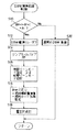
ここで、図3を参照すると、本発明に係るDBW異常処理制御ルーチンのフローチャートが示されており、以下、上記図2と図3とに基づき、DBW異常処理の制御手順について説明する。
図3のステップS10では、目標スロットル開度θTHTとTPS29から出力されるスロットル開度情報θTHとの差の絶対値が所定値X1より大きい(|θTHT−θTH|>X1)か否かを判別する。この判別は、即ち、DBW−T/B23に異常があるか否かの判別である。つまり、DBW−T/B23のステッパモータ24やTPS29が断線やショート等により異常作動しているか否かを判別している(異常検出手段)。
Here, FIG. 3 shows a flowchart of a DBW abnormality processing control routine according to the present invention. Hereinafter, a control procedure of the DBW abnormality processing will be described with reference to FIGS.
In step S10 of FIG. 3, it is determined whether or not the absolute value of the difference between the target throttle opening θTHT and the throttle opening information θTH output from the
通常、DBW−T/B23のステッパモータ24やTPS29が正常に作動していれば、APS72からの出力信号に基づく上記目標スロットル開度θTHTに応じてステッパモータ24が作動しスロットルバルブ28が開閉作動すると、TPS29からの出力信号、つまりスロットル開度θTHは、上記目標スロットル開度θTHTに応じたものとなるはずである。
Normally, if the
しかしながら、ステッパモータ24やTPS29に断線やショート等の故障が起こり、DBW−T/B23に異常が発生すると、スロットル開度θTHと目標スロットル開度θTHTとの差の絶対値はもはや所定値X1ではなくなる。従って、このステップS10では、このスロットル開度θTHと目標スロットル開度θTHTとの差を監視するようにし、これによりステッパモータ24やTPS29の異常、即ちDBW−T/B23の異常を判別するようにしている。
However, when a failure such as a disconnection or short circuit occurs in the
ステップS10の判別結果が真(Yes)で、スロットル開度θTHと目標スロットル開度θTHTとの差の絶対値が所定値X1より大きい(|θTHT−θTH|>X1)場合には、DBW−T/B23に異常があると判定でき、この場合には、次にステップS12に進む。
ステップS12では、通常エンジン1の運転時においてエンジン制御部70aからDBW電源リレー70cに供給している信号を断ち、DBW電源リレー70cをオフ状態とする。従って、バッテリ80からDBW制御部70bへの電源供給が遮断されてDBW制御部70bによる一切の制御が停止される。
If the determination result of step S10 is true (Yes) and the absolute value of the difference between the throttle opening θTH and the target throttle opening θTHT is larger than a predetermined value X1 (| θTHT−θTH |> X1), DBW−T / B23 can be determined to be abnormal, and in this case, the process proceeds to step S12.
In step S12, during the operation of the
これにより、DBW制御部70bからステッパモータ24への駆動信号の供給が停止され、ステッパモータ24は非通電状態となる(電流遮断手段)。このようにステッパモータ24が非通電状態となると、コイルスプリング28bの付勢力によってスロットルバルブ28が閉弁側に付勢されることになり、故に、スロットルバルブ28は閉状態とされる。
に よ り Thereby, the supply of the drive signal from the
即ち、DBW−T/B23に異常があるような場合、つまり、スロットルバルブ28が正常に作動しないような状況にあっては、エンジン1の運転状態が悪化するばかりでなく車両の走行状態が不安定なものとなる可能性があるのであるが、このようにスロットルバルブ28が閉弁状態、即ち原位置に戻されることで、そのような不具合が良好に防止されることになるのである。
That is, when there is an abnormality in the DBW-T /
しかしながら、スロットルバルブ28が閉弁状態とされると、吸気が殆ど行われなくなり、つまり、エンジン1の運転が略停止されることになる。このように、エンジン1の運転が略停止状態とされると、車両が走行中の場合にあっては、車両の走行状態が急変することになり好ましいことではない。
そこで、次のステップS14において、リンプホームバルブ27を開弁し、スロットルバルブ28が閉弁状態とされたと略同時にリンプホームパイプ26を介して吸気が行われるようにする。これにより、DBW−T/B23に異常がある場合には、リンプホームパイプ26を介してあまり多くはないが一定量の吸気が行われることになる。つまり、走行中にDBW−T/B23に異常が発生したような場合であっても、必要最小限の所定車速V1での走行が可能なようにされているのである。この車速V1としては、高速道路での走行をも考慮して、例えば、V1=80〜120km/hとされている。即ち、リンプホームパイプ26は、少なくともこの車速V1(V1=80〜120km/h)を確保可能なように流路面積が設定されている。
However, when the
Therefore, in the next step S14, the
ところで、リンプホームパイプ26を介して吸気が行われることになると、吸入空気量Qaが一定量に制限されることになるため、これに応じて燃料噴射量を設定する必要があり、これにより適正なエンジン1の出力トルクを得るようにしている。しかしながら、車両の走行安全性を向上させる上では、さらに、通常の走行時と同様にして出力トルクの可変制御ができるのが望ましい。
By the way, when the intake is performed through the
この点に関し、筒内噴射型のエンジン1では、燃料噴射モードが後期リーンモードのときに燃料噴射量を決定する目標A/Fが目標平均有効圧Peに基づいて設定されることからも明らかであるが、吸入空気量Qaが一定のときには、エンジン1の出力トルクは、図4に示すように燃料噴射量に良好に比例することが知られている。この関係は、燃料噴射モードが後期リーンモードの場合に限られず、前期リーンモードの場合にも良好に適用される。
In this regard, in the in-
つまり、筒内噴射型のエンジン1にあっては、後期噴射モードの場合には、燃料が常に点火プラグ3の周りに集められて着火され燃焼するために、燃料噴射量に応じて出力トルクを変化させることが可能であり、また、燃料噴射量を減らして前期リーンモードの場合に比べて空燃比をリーン化させてもエンジン回転変動が生じにくく、ドライバビリティを悪化させることがなく、一方、エンジン1が前期リーンモードでリーン燃焼しているときにおいても、燃焼室5内の層状流の作用によって燃料が常に点火プラグ3の周りに集められるために、やはり同様にして燃料噴射量に応じて出力トルクを変化させることが可能とされるのである。
That is, in the in-cylinder
従って、筒内噴射型のエンジン1では、次のステップS15において、例えば、車速Vに応じて強制的に燃料噴射モードを後期リーンモードまたは前期リーンモードに設定する(モード切換手段)。そして、次のステップS16において、目標スロットル開度θTHT、即ち、運転者のアクセルペダル74の踏込量に基づくAPS72の出力に応じて燃料噴射量を算出し、この燃料噴射量に基づいて燃料調節を行うようにしている。具体的には空燃比制御を行うようにしている。これにより、DBW−T/B23の異常によりスロットルバルブ28を作動停止した場合にあっても、運転者のアクセルペダル74操作に応じて出力トルクが良好に調節可能とされ、DBW−T/B23異常時の車両の走行安全性が確保される。
Therefore, in the in-cylinder
詳しくは、ここでは、出力トルクを調節することを目的とし、燃料噴射を行う気筒を選択して燃料噴射量を調節するようにしている。つまり一部の気筒(所定気筒)の燃料カットを行うことでエンジン1の出力トルクを調節する。従って、当該ステップS16では、燃料カット気筒の設定を行う(燃料制御手段)。
そして、燃料カットによって出力トルク調節を行う場合には、出力トルクは階段状に変化し、トルクショックが発生する虞があるため、燃料カットを行う気筒に応じて燃料噴射弁4から噴射する燃料噴射量の調節を行うようにし、出力トルクを徐々に変化させるようにする(燃料制御手段)。具体的には、空燃比をリーンとして出力を低下させた後に燃料カットを行い、このとき、燃料カットした気筒以外の気筒の空燃比を濃化させる。これにより、燃料カットを行ったときには出力トルクが急激に低下するのであるが、このような出力トルクの急激な低下が好適に防止される。そして、その後、空燃比を再度リーン化して上記燃料噴射量の調節による燃料制御を繰り返すようにする。これにより、燃料調節を燃料カットで行う場合であっても、出力トルクを徐々に滑らかに変化させて出力トルク調節を良好に行うことができることになる。
More specifically, here, the purpose is to adjust the output torque, and the cylinder for performing the fuel injection is selected to adjust the fuel injection amount. That is, the output torque of the
When the output torque is adjusted by the fuel cut, the output torque changes in a stepwise manner, and there is a possibility that a torque shock occurs. Therefore, the fuel injection injected from the fuel injection valve 4 according to the cylinder for which the fuel cut is performed. The amount is adjusted and the output torque is gradually changed (fuel control means). Specifically, the fuel cut is performed after the output is reduced with the air-fuel ratio being lean, and at this time, the air-fuel ratios of the cylinders other than the fuel-cut cylinder are enriched. As a result, when the fuel cut is performed, the output torque sharply decreases, but such a sharp decrease in the output torque is preferably prevented. After that, the air-fuel ratio is made lean again and the fuel control by adjusting the fuel injection amount is repeated. As a result, even when the fuel adjustment is performed by the fuel cut, the output torque can be satisfactorily adjusted by gradually and smoothly changing the output torque.
そして、ステップS18では、DBW−T/B23に異常があって上記一連の処理を行っていることを運転者に知らせるため、警告灯76を点灯させる。
ところで、上記ステップS10の判別結果が偽(No)で、スロットル開度θTHと目標スロットル開度θTHTとの差の絶対値が所定値X1以下(|θTHT−θTH|≦X1)の場合には、DBW−T/B23は正常と判定でき、この場合には、次にステップS20に進み、通常のDBW制御を行う。つまり、この場合には、上述したようにして燃焼制御が適正に行われ、DBW制御部70bによって良好にステッパモータ24が制御される。
Then, in step S18, the
If the result of the determination in step S10 is false (No) and the absolute value of the difference between the throttle opening θTH and the target throttle opening θTHT is equal to or smaller than a predetermined value X1 (| θTHT−θTH | ≦ X1), The DBW-T /
以上、詳細に説明したように、本発明の内燃エンジンの制御装置によれば、電子式吸入空気量制御弁装置、即ちドライブバイワイヤ型のスロットルボディ(DBW−T/B)23を有しており、このDBW−T/B23に異常が発生したような場合には、スロットルバルブ28を閉弁状態とするとともにリンプホームバルブ27を開弁し、これによりリンプホームパイプ26を介しDBW−T/B23をバイパスするようにして一定量の吸気を行うようにしている。
As described above in detail, according to the control apparatus for an internal combustion engine of the present invention, the electronic intake air amount control valve device, that is, the drive-by-wire type throttle body (DBW-
従って、ステッパモータ24やTPS29等に故障が発生し、DBW−T/B23が異常状態になったことが確認されたときには、スロットルバルブ28を閉弁してエンジン1の運転状態の悪化を防止できるとともに、リンプホームパイプ26を介して一定量の吸気を行うことで、通常運転時よりもエンジン1の出力トルクは制限されるものの、安定したエンジン1の運転状態を維持することができる。
Therefore, when a failure occurs in the
さらに、本発明の内燃エンジンの制御装置によれば、エンジン1が筒内噴射型であって且つリーン空燃比運転可能な内燃エンジンであるため、燃料噴射モードを後期リーンモードまたは前期リーンモードに設定することで、一定量の吸気のもとに、アクセルペダル74の踏込量に応じて一部の気筒の燃料カットとともに燃料噴射量の調節を行って出力トルクを良好に調節でき、故に、車両の走行中においてDBW−T/B23が異常状態となっても、車両の走行状態を通常の走行状態のときと同様にして好適に可変制御することができる。これにより、従来のようにアクセル索を別途設けることなく、DBW−T/B23の異常時において、走行安全性とともに比較的良好なドライバビリティを確保することが可能とされる。
Further, according to the internal combustion engine control device of the present invention, since the
なお、上記実施形態では、エンジン1を筒内噴射型のリーン空燃比運転可能な内燃エンジンとしたが、通常の吸気管噴射型の内燃エンジンに適用することも可能である。この場合、内燃エンジンが吸気管噴射型でありながらリーン空燃比運転可能に設計されていれば、混合気の層状化によって燃料を点火プラグ近傍に好適に集めることができるため、上記同様に燃料調節を実施して出力トルク調節を行うことができる。一方、リーン空燃比運転可能に設計されていない内燃エンジンのように、燃焼可能な空燃比が理論空燃比AFS近傍のみと狭く、出力トルク調節を燃料噴射量の調節で行うことが困難である場合であっても、燃料カットによって出力トルク調節を行うようにできる。
In the above-described embodiment, the
また、上記実施形態では、DBW−T/B23の異常時には、リンプホームパイプ26とリンプホームバルブ27とを用いてDBW−T/B23をバイパスするようにして一定量の吸気を行うようにしたが、これに限られず、例えば、上記ストッパ28c(図2参照)に電磁式のアクチュエータを連結し、DBW−T/B23の異常が検出されたときにこの電磁式のアクチュエータにECU70から駆動信号を供給してストッパ28cを突出させるような構成にしてもよい(全閉位置変更手段)。これにより、ステッパモータ24への信号供給が停止されたときでもスロットルバルブ28を閉塞させることなく僅かに開弁させた状態に保持でき、上記リンプホームパイプ26を介して吸気したときの吸気量と略同量の吸気が可能とされる。故に、上記実施形態同様の効果が得られる。
Further, in the above embodiment, when the DBW-T / B23 is abnormal, the
また、上記実施形態では、DBW−T/B23、即ちステッパモータ24、TPS29等に異常が発生したときにのみ警告灯76を点灯させるようにしたが、これに加え、例えば、ECU70にリンプホームバルブ27の断線やショートによる異常の検出機能を持たせ、このリンプホームバルブ27の異常が検出されたときに警告灯76を点灯させるようにしてもよい。これにより、リンプホームバルブ27を常に作動可能な状態に維持しておくことが可能とされる。
In the above-described embodiment, the warning
また、上記実施形態では、APS72を一個のみ用いるようにしたが、検出精度の安定性を考慮して複数設けるようにするのがよい。
In the above embodiment, only one
1 エンジン(筒内噴射型火花点火式内燃エンジン)
4 燃料噴射弁
23 DBW−T/B(スロットル弁装置)
24 ステッパモータ
26 リンプホームパイプ(補助吸気手段、バイパス通路)
27 リンプホームバルブ
28 スロットルバルブ(スロットル弁)
28a コイルスプリング(駆動手段、付勢手段)
28c ストッパ
29 TPS(スロットル開度検出手段)
70 電子制御ユニット(ECU)
72 APS(加速操作量検出手段)
76 警告灯
1 engine (in-cylinder injection spark ignition internal combustion engine)
4
24
27
28a coil spring (driving means, biasing means)
70 Electronic Control Unit (ECU)
72 APS (acceleration operation amount detection means)
76 Warning Light
Claims (7)
内燃エンジンの加速操作を行う加速操作部材の操作量を検出する加速操作量検出手段と、
前記加速操作量検出手段の検出結果に基づき駆動されるモータ、及び、前記内燃エンジンの吸気管に配設され、前記モータにより開閉駆動されるスロットル弁を有するスロットル弁装置と、
前記スロットル弁装置の異常を検出する異常検出手段と、
前記異常検出手段により前記異常が検出されたとき、前記スロットル弁を閉方向に駆動する駆動手段と、
前記異常検出手段により前記異常が検出されたとき、前記内燃エンジンの燃焼室に所定量の空気を導入可能な補助吸気手段と、
前記異常検出手段により前記異常が検出されたとき、前記圧縮行程噴射モードに切り換えるモード切換手段と、
前記異常検出手段により前記異常が検出されたとき、前記所定量の空気と前記加速操作量検出手段の検出結果とに応じて前記複数の気筒のうち所定気筒の燃料カットを行うことで出力トルクを制御する燃料制御手段と、
を備えたことを特徴とする内燃エンジンの制御装置。 An intake stroke injection mode in which fuel is directly injected into each combustion chamber of a plurality of cylinders and fuel is injected in an intake stroke according to an operation state, and a compression stroke injection mode in which fuel is injected in a compression stroke. And a lean air-fuel ratio operable internal combustion engine control device,
Acceleration operation amount detection means for detecting an operation amount of an acceleration operation member for performing an acceleration operation of the internal combustion engine,
A motor that is driven based on the detection result of the acceleration operation amount detection unit, and a throttle valve device that is disposed in an intake pipe of the internal combustion engine and has a throttle valve that is opened and closed by the motor.
Abnormality detection means for detecting an abnormality of the throttle valve device;
When the abnormality is detected by the abnormality detection unit, a driving unit that drives the throttle valve in a closing direction,
When the abnormality is detected by the abnormality detection unit, an auxiliary intake unit that can introduce a predetermined amount of air into a combustion chamber of the internal combustion engine;
A mode switching unit that switches to the compression stroke injection mode when the abnormality is detected by the abnormality detection unit;
When the abnormality is detected by the abnormality detecting means, an output torque is obtained by performing fuel cut of a predetermined cylinder among the plurality of cylinders according to the predetermined amount of air and a detection result of the acceleration operation amount detecting means. Controlling fuel control means;
A control device for an internal combustion engine, comprising:
内燃エンジンの加速操作を行う加速操作部材の操作量を検出する加速操作量検出手段と、
前記加速操作量検出手段の検出結果に基づき駆動されるモータ、及び、前記内燃エンジンの吸気管に配設され、前記モータにより開閉駆動されるスロットル弁を有するスロットル弁装置と、
前記スロットル弁装置の異常を検出する異常検出手段と、
前記異常検出手段により前記異常が検出されたとき、前記スロットル弁を閉方向に駆動する駆動手段と、
前記異常検出手段により前記異常が検出されたとき、前記内燃エンジンの燃焼室に所定量の空気を導入可能な補助吸気手段と、
前記異常検出手段により前記異常が検出されたとき、前記圧縮行程噴射モードに切り換えるモード切換手段と、
前記異常検出手段により前記異常が検出されたとき、前記所定量の空気と前記加速操作量検出手段の検出結果とに応じて前記複数の気筒のうち所定気筒の燃料カットを行うとともに該燃料カットに応じて前記各燃焼室に供給する燃料噴射量を制御する燃料制御手段と、
を備えたことを特徴とする内燃エンジンの制御装置。 An intake stroke injection mode in which fuel is directly injected into each combustion chamber of a plurality of cylinders and fuel is injected in an intake stroke according to an operation state, and a compression stroke injection mode in which fuel is injected in a compression stroke. And a lean air-fuel ratio operable internal combustion engine control device,
Acceleration operation amount detection means for detecting an operation amount of an acceleration operation member for performing an acceleration operation of the internal combustion engine,
A motor that is driven based on the detection result of the acceleration operation amount detection unit, and a throttle valve device that is disposed in an intake pipe of the internal combustion engine and has a throttle valve that is opened and closed by the motor.
Abnormality detection means for detecting an abnormality of the throttle valve device;
When the abnormality is detected by the abnormality detection unit, a driving unit that drives the throttle valve in a closing direction,
When the abnormality is detected by the abnormality detection unit, an auxiliary intake unit that can introduce a predetermined amount of air into a combustion chamber of the internal combustion engine;
A mode switching unit that switches to the compression stroke injection mode when the abnormality is detected by the abnormality detection unit;
When the abnormality is detected by the abnormality detection means, a fuel cut of a predetermined cylinder among the plurality of cylinders is performed in accordance with the predetermined amount of air and a detection result of the acceleration operation amount detection means, and the fuel cut is performed. Fuel control means for controlling a fuel injection amount to be supplied to each of the combustion chambers,
A control device for an internal combustion engine, comprising:
前記異常検出手段は、前記加速操作量検出手段の検出結果と前記スロットル開度検出手段の検出結果との比較に基づいて前記異常を検出することを特徴とする、請求項1乃至3のいずれか記載の内燃エンジンの制御装置。 The throttle valve device further includes a throttle opening detection unit that detects an opening of the throttle valve,
4. The apparatus according to claim 1, wherein the abnormality detection unit detects the abnormality based on a comparison between a detection result of the acceleration operation amount detection unit and a detection result of the throttle opening detection unit. A control device for an internal combustion engine according to any of the preceding claims.
Priority Applications (1)
| Application Number | Priority Date | Filing Date | Title |
|---|---|---|---|
| JP2004030718A JP4092579B2 (en) | 2004-02-06 | 2004-02-06 | Control device for internal combustion engine |
Applications Claiming Priority (1)
| Application Number | Priority Date | Filing Date | Title |
|---|---|---|---|
| JP2004030718A JP4092579B2 (en) | 2004-02-06 | 2004-02-06 | Control device for internal combustion engine |
Related Parent Applications (1)
| Application Number | Title | Priority Date | Filing Date |
|---|---|---|---|
| JP23231996A Division JPH1077891A (en) | 1996-09-02 | 1996-09-02 | Control device for internal combustion engine |
Publications (2)
| Publication Number | Publication Date |
|---|---|
| JP2004138077A true JP2004138077A (en) | 2004-05-13 |
| JP4092579B2 JP4092579B2 (en) | 2008-05-28 |
Family
ID=32464231
Family Applications (1)
| Application Number | Title | Priority Date | Filing Date |
|---|---|---|---|
| JP2004030718A Expired - Lifetime JP4092579B2 (en) | 2004-02-06 | 2004-02-06 | Control device for internal combustion engine |
Country Status (1)
| Country | Link |
|---|---|
| JP (1) | JP4092579B2 (en) |
Cited By (3)
| Publication number | Priority date | Publication date | Assignee | Title |
|---|---|---|---|---|
| JP2007231833A (en) * | 2006-03-01 | 2007-09-13 | Denso Corp | Exhaust control device for internal combustion engine |
| JP2009287476A (en) * | 2008-05-29 | 2009-12-10 | Honda Motor Co Ltd | Intake air control device for general purpose engine |
| JP2010133395A (en) * | 2008-12-08 | 2010-06-17 | Mitsubishi Motors Corp | Control device for internal combustion engine |
-
2004
- 2004-02-06 JP JP2004030718A patent/JP4092579B2/en not_active Expired - Lifetime
Cited By (4)
| Publication number | Priority date | Publication date | Assignee | Title |
|---|---|---|---|---|
| JP2007231833A (en) * | 2006-03-01 | 2007-09-13 | Denso Corp | Exhaust control device for internal combustion engine |
| JP4577236B2 (en) * | 2006-03-01 | 2010-11-10 | 株式会社デンソー | Exhaust control device for internal combustion engine |
| JP2009287476A (en) * | 2008-05-29 | 2009-12-10 | Honda Motor Co Ltd | Intake air control device for general purpose engine |
| JP2010133395A (en) * | 2008-12-08 | 2010-06-17 | Mitsubishi Motors Corp | Control device for internal combustion engine |
Also Published As
| Publication number | Publication date |
|---|---|
| JP4092579B2 (en) | 2008-05-28 |
Similar Documents
| Publication | Publication Date | Title |
|---|---|---|
| KR100310094B1 (en) | The control system of cylnder injection type internal combustion enging with pryo-ignition method | |
| JP3175535B2 (en) | Idle speed control device for internal combustion engine | |
| JP3772891B2 (en) | Engine starter | |
| US6779508B2 (en) | Control system of internal combustion engine | |
| JPH08312401A (en) | Fuel injection control device for spark ignition internal combustion engine of cylinder injection type | |
| JP3186598B2 (en) | Control device for internal combustion engine | |
| JP3731025B2 (en) | Air quantity control device for internal combustion engine | |
| JP3913864B2 (en) | In-cylinder injection fuel control system for internal combustion engine | |
| JPH1061477A (en) | Controller for inner-cylinder injection spark ignition type internal combustion engine | |
| JPH10169449A (en) | Controller for cylinder injection type internal combustion engine | |
| JPH1193731A (en) | Fuel injection control device for cylinder injection internal combustion engine | |
| JP3265997B2 (en) | Control device for internal combustion engine | |
| JP4092579B2 (en) | Control device for internal combustion engine | |
| JP5925099B2 (en) | Control device for internal combustion engine | |
| JP2005315203A (en) | Engine starter | |
| JP2010014061A (en) | Control device for vehicle | |
| JP3233031B2 (en) | In-cylinder injection spark ignition internal combustion engine | |
| JP4339599B2 (en) | In-cylinder injection internal combustion engine control device | |
| JP3757998B2 (en) | In-cylinder injection type internal combustion engine control device | |
| JP3186599B2 (en) | In-cylinder injection spark ignition internal combustion engine | |
| JP3185602B2 (en) | Fuel injection control device for in-cylinder injection spark ignition internal combustion engine | |
| JP3735138B2 (en) | Intake control device | |
| JPH1077891A (en) | Control device for internal combustion engine | |
| JP3269350B2 (en) | In-cylinder spark ignition internal combustion engine | |
| JP3233038B2 (en) | Control device for in-cylinder injection spark ignition internal combustion engine |
Legal Events
| Date | Code | Title | Description |
|---|---|---|---|
| A621 | Written request for application examination |
Effective date: 20040206 Free format text: JAPANESE INTERMEDIATE CODE: A621 |
|
| A131 | Notification of reasons for refusal |
Effective date: 20070523 Free format text: JAPANESE INTERMEDIATE CODE: A131 |
|
| A521 | Written amendment |
Free format text: JAPANESE INTERMEDIATE CODE: A523 Effective date: 20070718 |
|
| A131 | Notification of reasons for refusal |
Effective date: 20071121 Free format text: JAPANESE INTERMEDIATE CODE: A131 |
|
| A521 | Written amendment |
Effective date: 20080110 Free format text: JAPANESE INTERMEDIATE CODE: A523 |
|
| TRDD | Decision of grant or rejection written | ||
| A01 | Written decision to grant a patent or to grant a registration (utility model) |
Free format text: JAPANESE INTERMEDIATE CODE: A01 Effective date: 20080206 |
|
| A61 | First payment of annual fees (during grant procedure) |
Effective date: 20080219 Free format text: JAPANESE INTERMEDIATE CODE: A61 |
|
| FPAY | Renewal fee payment (prs date is renewal date of database) |
Free format text: PAYMENT UNTIL: 20110314 Year of fee payment: 3 |
|
| FPAY | Renewal fee payment (prs date is renewal date of database) |
Free format text: PAYMENT UNTIL: 20110314 Year of fee payment: 3 |
|
| FPAY | Renewal fee payment (prs date is renewal date of database) |
Year of fee payment: 3 Free format text: PAYMENT UNTIL: 20110314 |
|
| FPAY | Renewal fee payment (prs date is renewal date of database) |
Year of fee payment: 4 Free format text: PAYMENT UNTIL: 20120314 |
|
| FPAY | Renewal fee payment (prs date is renewal date of database) |
Free format text: PAYMENT UNTIL: 20120314 Year of fee payment: 4 |
|
| FPAY | Renewal fee payment (prs date is renewal date of database) |
Year of fee payment: 5 Free format text: PAYMENT UNTIL: 20130314 |