JP2004137763A - Door handle device and assembling method for door handle - Google Patents
Door handle device and assembling method for door handle Download PDFInfo
- Publication number
- JP2004137763A JP2004137763A JP2002303400A JP2002303400A JP2004137763A JP 2004137763 A JP2004137763 A JP 2004137763A JP 2002303400 A JP2002303400 A JP 2002303400A JP 2002303400 A JP2002303400 A JP 2002303400A JP 2004137763 A JP2004137763 A JP 2004137763A
- Authority
- JP
- Japan
- Prior art keywords
- shaft
- elastic member
- locking
- guide surface
- door handle
- Prior art date
- Legal status (The legal status is an assumption and is not a legal conclusion. Google has not performed a legal analysis and makes no representation as to the accuracy of the status listed.)
- Granted
Links
Images


Abstract
Description
【0001】
【発明の属する技術分野】
本発明は、車両のドアを外部から開閉する際に操作するドアハンドル装置及びそのドアハンドルの組み付け方法に関する。
【0002】
【従来の技術】
車両用のドアのドアアウターパネルにはドアを外部から開閉操作するドアハンドルが装着される。
ドアハンドルはドアアウターパネルに固定されるベースと、ベースの本体より延出する軸受け部に枢支軸を介してアーム部が枢支されるハンドルノブとを備える。このドアハンドルが取付けられるドアアウターパネルにはドアハンドルを装着するための凹部が形成され、同凹部の一部に開口や取付片部が形成される。ドアハンドルはベース及びハンドルノブが凹部に嵌合され、同時にベースの締め付け固定部が取付片部に重ね合わされ適宜の締め付け手段で締め付け結合される。しかも、ベースの枢支部や同枢支部に枢支軸を介して枢着されるハンドルノブのアームは開口を遊嵌状態で嵌挿され、ドアアウターパネル内室に配設される。取付片部に固定されたベースの枢支部とハンドルノブのアームに形成された軸受け部とは長ピン状の枢支軸を介して枢着される。このため、ハンドルノブが枢支軸回りに引き上げ操作されることにより、ハンドルノブのアームが枢支軸回りにてこ作動し、アームの揺動端がドアロック機構に連結される開閉用リンク系の一端をロック解除方向に作動できる。
【0003】
このようなドアハンドル装置は各種の構成を採り、例えば、特開平11−200669号公報(特許文献1)のドアハンドル装置は、ドアアウターパネルの開口を覆うハンドルケース14のケースアーム14eにハンドルノブ15のハンドルアーム15bを回転軸18でピン結合した構成を開示する。ここではハンドルケース14を開口の縁部の取付けフランジ12bにボルト止めするとともにフック状の一対の当接部14cを開口の縁部に係止してハンドルケース14をぐらつき無く取付けできる。
【0004】
特開平10−205181号公報(特許文献2)のドアハンドル装置は、ドアパネルの開口を覆うハンドルケース23のハンドルケースアーム23cにハンドル把持部40のハンドルアーム45をシャフト60でピン結合した構成を開示する。ここではシャフト60に外嵌されハンドル把持部40を閉操作方向に付勢するリターンスプリング80の先端部80aでハンドルアーム45の揺動端に取付けられるバランスウエイト30を係止し、離脱を防止している。
【0005】
特開平10−299297号公報(特許文献3)のドアハンドル装置は、ドアパネルの開口を覆うハンドルベース8の支持脚84に手掛け部11のアーム10、10’をヒンジ軸80でピン結合した構成を開示する。ここでは手掛け部11を閉操作方向に付勢するトーションスプリング81がヒンジ軸80に外嵌され、手掛け部11のアーム10、10’の揺動端にバランスウエイト2が嵌着され、クリップ7および円弧状押え面14aの働きでバランスウエイト2の離脱を阻止している。
【0006】
特開2001−140506号公報(特許文献4)のドアハンドル装置は、ドアパネルの開口を覆うハンドルベース1のベースアーム1bにハンドル本体2のハンドルアーム2b、2b’を支軸11でピン結合した構成を開示する。ここではハンドル本体2を閉操作方向に付勢するトーションスプリング3が支軸11に外嵌され、ハンドル本体2より延出するハンドルアーム2b、2b’のウエイト受け部4、4’に棒状のカウンタウエイト7が差込み嵌着され、カウンタウエイト7のスプリング嵌合溝5にトーションスプリング3の先端部が係合することでカウンタウエイト7のがたつきを防止している。
【0007】
このような各ドアハンドル装置は、ドアアウターパネルに固定されるベースやハンドルノブ等の形状等に相違があるものの、いずれもベース側の枢支部にハンドルノブより延出するアームの軸受け部が重ねられ、両者に枢支軸を貫通させた上で、適宜の抜け止め処理を行なうものである。
【0008】
更に、図8(a)、(b)に示すドアハンドル装置は、ハンドル本体100の一対の軸受け凸部110、120と不図示のドアアウターパネルに固定されるベース130側の一対の枢支部131、132とをピン状の軸部材140を介して枢着している。このドアハンドル装置はハンドル本体100を閉操作方向に付勢するバネ150を軸部材140に外嵌し、その軸部材をベース130に組込んで仮組し、その仮組体mをハンドル本体100に組み付けるようにしている。
【0009】
【特許文献1】
特開平11−200669号
【特許文献2】
特開平10−205181号
【特許文献3】
特開平10−299297号
【特許文献4】
特開2001−140506号
【0010】
【発明が解決しようとする課題】
ところで、上述の特許文献1乃至4に開示した各ドアハンドル装置では、ベース側の枢支部とハンドルノブより延出するアームの軸受け部とを重ねた上でこれらを貫通するように軸部材を取付け、軸部材には抜け止め処理が成されるものであり、組み付け時の作業工数が比較的多くなる。
【0011】
これに対して、図8(a)、(b)に示すドアハンドル装置では、バネ150を外嵌した軸部材130側の両側部をベース130の一対の枢支部131、132に差込み、しかも、バネ150の先に組込まれる先側係止端部151をベース130に係止して仮組体mを形成している。軸部材140にはフランジ143が形成され、これにバネ150が係合して軸方向に弾性力を付加できるようにしている。
【0012】
このような仮組み体mをハンドル本体100に組み付けるには、ハンドル本体2の一対の軸受け凸部110、120に形成される軸端部受け穴160の一方に軸部材140の先に組込まれる先側端部141を差込む。その後、先側端部141をバネ150の弾性力に抗して軸端部受け穴160内に深く押し込みつつ、軸部材140の後に組込まれる後側端部142を軸端部受け穴160の他方に対向させ、嵌挿させる。その上でバネ150の後に組込まれる後側係止端部152を弾性変形させ、ハンドル本体2に形成される弾性部材係止溝170に嵌合させている。
【0013】
このようなドアハンドル装置では、軸部材140の両端部が一対の軸端部受け穴160に嵌合し、バネ150の弾性力で軸部材のずれが防止されると、その後で抜け止め処理をする必要が無く、組み付け工数が低減される。しかし、軸部材140の先側端部141をバネ150の弾性力に抗して軸端部受け穴160の一方に深く押し込みつつ、後側端部142を軸端部受け穴160の他方に対向させ、嵌挿させる作業に手間取る。しかも、バネ150の後側係止端部152をハンドル本体2の弾性部材係止溝170に嵌合させるのに適宜の工具を必要とし、嵌挿作業に手間取り、工数大、コスト増を招くこととなる。
本発明は、以上のような課題に基づきなされたもので、組み付け工数低減を図れ、コスト削減及び生産性向上を図るドアハンドル装置及びドアハンドルの組み付け方法を提供することを目的とする。
【0014】
【課題を解決するための手段】
請求項1の発明は、車体に取付けられるべ一ス部材に軸部材を介して回動自在に支持されるレバー部材と、上記レバー部材を閉操作方向に付勢する弾性部材とを有するドアハンドル装置において、上記レバー部材は、上記軸部材の両側端部のうち組み込みが後となる後側端部を嵌合する軸端部受け穴と、同軸端部受け穴に上記後側端部を案内する軸端部ガイド面と、上記弾性部材の両係止端部のうち組み込みが後となる後側係止端部を係止する弾性部材係止溝と、上記軸部材の後側端部を上記軸端部ガイド面に沿って案内するための押圧力を上記弾性部材の後側係止端部にも加えた際に、同後側係止端部を弾性変形させつつ上記弾性部材係止溝に案内する弾性部材ガイド面と、を有することを特徴とする。
このように弾性部材を外嵌した軸部材を組み込んだベース部材を仮組み体とし、同仮組み体をレバー部材に組込むにあたり、このレバー部材に軸端部ガイド面と弾性部材ガイド面とを設けたので、まず、軸部材の両側端部のうち組み付けが先の先側端部を軸端部受け穴の一方に嵌合し、その上で軸端部ガイド面に沿って組み込みが後となる後側係止端部を弾性部材ガイド面に沿って案内するための押圧力を加え、これと同時に、弾性部材の後側係止端部を押圧して弾性変形させつつ弾性部材ガイド面に沿って弾性部材係止溝に案内することができ、このため、レバー部材への軸部材と弾性部材の組み付け作業が簡易化される。
【0015】
請求項2の発明は、請求項1に記載のドアハンドル装置において、上記弾性部材は組み付けが先となる先側係止端部を上記べ一ス部材に係止するよう設けられると共に、上記べ一ス部材に先側端部が組み付けられた軸部材の後側端部を同後側端部と嵌合する上記軸端部受け穴の側に付勢するよう設けらたことを特徴とするドアハンドル装置。
このように、レバー部材を閉操作方向に付勢するために設けられている弾性部材を利用して軸部材の後側端部を同後側端部と嵌合する軸端部受け穴の側へ付勢するようにしたので、軸部材の後側端部が軸端部受け穴へ案内され嵌合する際、軸部材の後側端部を軸端部受け穴に弾性的に押圧して嵌合させるので、軸部材の組み付け作業が簡易化される。
【0016】
請求項3の発明は、車体に取付けられるべ一ス部材に軸部材を介して回動自在に支持されるレバー部材と、同レバー部材を閉操作方向に付勢する弾性部材とを有し、上記レバー部材には上記軸部材の両側端部のうち先に組込まれる先側端部と後に組込まれる後側端部とがそれぞれ嵌合する一対の軸端部受け穴を形成したドアハンドル装置において、上記べ一ス部材は上記軸部材の両側部を支持する一対の取付孔が設けられ、上記軸部材は上記一対の取付孔で支持される間の中間部にフランジ部が形成され、上記弾性部材は上記軸部材に外嵌される巻きバネ形状部を備え、上記レバー部材に先に組込まれる先側係止端部と上記レバー部材に後に組込まれる後側係止端部とがそれぞれ形成され、且つ、上記一対の軸端部受け穴の一方に先側端部が組込まれた軸部材の後側端部を上記フランジ部を介して上記軸端部受け穴の他方に付勢するよう設けられ、上記レバー部材は、上記軸端部受け穴の一方に先側端部が組込まれた軸部材の後側端部を軸端部受け穴の他方に案内する軸端部ガイド面と、上記弾性部材の後側係止端部を係止する弾性部材係止溝と、上記軸部材の後側端部を上記軸端部ガイド面に沿って案内するための押圧力を上記弾性部材の後側係止端部にも加えた際に、同後側係止端部を弾性変形させつつ上記弾性部材係止溝に案内する弾性部材ガイド面と、を有することを特徴とする。
【0017】
このように弾性部材の巻きバネ形状部を外嵌した軸部材の両側端部のうち、組み付けが先の先側端部を軸端部受け穴の一方に嵌合してベース部材を仮組み体とした上で、この仮組み体を軸端部ガイド面と弾性部材ガイド面とを設けたレバー部材に組込む。この組み付けにあたり、まず、組み込みが後となっている後側端部に押圧力を加えて軸端部ガイド面に沿って軸端部受け穴の他方に案内し、これと同時に、弾性部材の後側係止端部を押圧し、この押圧操作を強めることで、後側端部が軸端部受け穴に達し、この際に弾性部材の巻きバネ形状部によりフランジ部を介して弾性的に押圧されている軸部材の後側端部を軸端部受け穴の他方に嵌合させ、しかも、弾性部材の後側係止端部が押圧力で弾性変形して弾性部材ガイド面に沿って摺動して弾性部材係止溝に案内することができる。このため、レバー部材への軸部材と弾性部材の組み付け作業が簡易化される。
【0018】
請求項4の方法発明は、車体に取付けられるべ一ス部材に軸部材を介して回動自在に支持されるレバー部材と、同レバー部材を閉操作方向に付勢する弾性部材とを有し、上記レバー部材は、上記軸部材の両側端部のうち先に組込まれる先側端部と後に組込まれる後側端部とがそれぞれ嵌合する一対の軸端部受け穴と、同軸端部受け穴に上記後側端部を案内する軸端部ガイド面と、上記弾性部材の両係止端部のうち組み込みが後となる後側係止端部を係止する弾性部材係止溝と、上記後側係止端部を弾性変形させた上で上記弾性部材係止溝に案内する弾性部材ガイド面とを備えて成るドアハンドルの組み付け方法であって、上記弾性部材に形成した巻きバネ形状部を外嵌した上記軸部材がその先側端部を上記軸端部受け穴の一方に嵌合してベース部材を仮組みする工程と、上記ベース部材に仮組みされた軸部材の後側端部に押圧力を加えて軸端部ガイド面に沿って軸端部受け穴の他方に対向させ、この押圧力の一部を弾性部材の後側係止端部にも加えて弾性部材ガイド面に沿って摺動させて弾性部材係止溝に対向させる押圧工程と、上記押圧工程後に上記弾性部材の巻きバネ形状部によりフランジ部を介して弾性的に軸端部ガイド面に押圧されている軸部材の後側端部を軸端部受け穴の他方に嵌合させ、しかも、弾性部材ガイド面に沿って摺動してきた弾性部材の後側係止端部を弾性部材係止溝に嵌合させる嵌合工程と、を行なうことを特徴とする。
【0019】
このように仮組み工程で上記弾性部材を外嵌した軸部材の先側端部をベース部材の軸端部受け穴の一方に嵌合し、押圧工程でベース部材に仮組みされた軸部材の後側端部を軸端部受け穴の他方に対向させ、しかも弾性部材の後側係止端部も弾性部材ガイド面に沿って摺動させて弾性部材係止溝に対向させ、嵌合工程で、軸部材の後側端部を軸端部受け穴の他方に嵌合させ、しかも、弾性部材の後側係止端部を弾性部材係止溝に嵌合させる。このように、仮組み工程、押圧工程、嵌合工程の各処理が容易化され、しかも、弾性部材を外嵌すると共にベース部材に仮組みされた軸部材をレバー部材へ組み付ける作業が簡易化される。
【0020】
【発明の実施の形態】
以下、本発明の一実施形態としてのドアハンドル装置とドアハンドルの組み付け方法を図1乃至図7を参照して説明する。
ドアハンドル装置は図示しない車両の側壁開口を開放可能に閉鎖する不図示のドアのドアアウターパネル1に装着される。
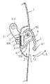
図1に示すように、ドアアウターパネル1にはドアハンドル装置を装着するための略楕円状の凹部である取付け凹部2が形成される。取付け凹部2にはその上側域の要部に車体前後方向Xに長い開口3が形成され、開口3の下縁部には固定部4が開口側に突き出すように形成され、同部に一対の貫通孔5が形成される。
【0021】
図2に示すように、ドアハンドル装置はドアアウターパネル1の固定部4に固定されるベース部材6と、ベース部材6に軸部材であるピン9を介して回動可能に保持された把持部を成すレバー部材7と、レバー部材7を閉操作方向Zに付勢する弾性部材としてのスプリング8(図3参照)とを備えている。
【0022】
図2、3、5(c)に示すように、ベース部材6は矩形状で固定部4に重ねられる主部601と、主部601の両側端より屈曲して延出する軸受け部602と、主部601の中央の切欠孔603と、切欠孔603の縁部より屈曲して突き出し後述するスプリング8の先側係止端801を係止する係止片604と、主部601の中央の切欠孔603を挟んで一対突き出して配置される取付けネジ605とを備える。
【0023】
図1乃至図4に示すように、レバー部材7は把持部701と、把持部701の裏側に突き出し形成された一対の軸受け凸部702、703と、把持部701の裏側より車体前後方向Xに沿って長く形成された中央覆い部704と、把持部701の裏側の両端部より車体前後方向Xに沿って連続形成された一対の前後覆い部705と、軸受け凸部703よりドアアウターパネル1の内部空間(図2で紙面左側)に向け延出するアーム11とを備える。
【0024】
把持部701は、図2、3、4に示すように、ドアアウターパネル1の取付け凹部2に離脱方向に揺動操作可能に嵌着される。把持部701の下縁部は取付け凹部2との間に隙間e(図2参照)を確保するように形成され、これにより、操作者の指が容易に把持部701の下縁部に係合できるようにしている。
把持部701の裏側に形成された中央覆い部704及び一対の前後覆い部705はその延出端部dが取付け凹部2の凹壁面に接近するよう延出形成される。これにより把持部701の非操作時において、把持部701の下縁部より取付け凹部2との間の隙間eを通して開口3が目視されることを防止できる。
【0025】
図3に示すように、一対の軸受け凸部702、703は車体前後方向Xにおいて所定間隔を保つ状態で把持部701の裏壁面より突き出し形成される。
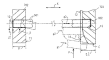
図3、7に示すように、一対の軸受け凸部702、703はそれぞれ車体前後方向Xに所定厚さt1、t2を有する厚板状を成し、向かい合う対向壁面f1、f2を有し、これら対向壁面f1、f2に後述のピン9を嵌合する軸端部受け穴12、13がそれぞれ形成される。
一方の軸受け凸部702には軸端部受け穴12が貫通孔として形成され、その対向壁面f1は平面を成すように形成される。
【0026】
他方のピン9の後述する後側端部902と嵌合する軸受け凸部703には軸端部受け穴13が形成され、その近傍の対向壁面f2にガイド溝14が形成される。ガイド溝14は突き出し面C側より軸端部受け穴13に延びる凹溝である。ガイド溝14はその溝底が後述のピン9を案内する軸端部ガイド面f3を形成している。ガイド溝14は突き出し面C側で最も深く形成され、軸端部受け穴13に達する部分c2で最も浅く形成される。
【0027】
更に、図4、6に示すように、軸受け凸部703はその軸端部受け穴13及びガイド溝14の下側近傍に弾性部材係止溝15を形成される。軸受け凸部703はその突き出し面C上であって、ガイド溝14より下側の位置に凸状湾曲面を成す弾性部材ガイド面f4を形成しており、その弾性部材ガイド面f4の下端に連続して弾性部材係止溝15を切り込み形成している。
【0028】
一方、図2、3に示すように、軸受け凸部702より延出するアーム11はその突端近傍に係止孔111を形成される。係止孔111には不図示のドアロック機構に連結される開閉用リンク系の一端が係合される。このため、把持部701が引き上げ操作(図2の矢視U方向)されてピン9回りに回動すると、アーム11がピン9回りにてこ作動し、アーム11の揺動端に連結される不図示のドアロック機構開閉用リンク系をロック解除方向に作動できる。
【0029】
図5(c)に示すように、べ一ス部材6の主部601の両側端より延出する一対の軸受け部602には、図5(a)に示すような軸部材であるピン9が嵌挿され、ピン9には図5(b)に示すような弾性部材としてのスプリング8が外嵌される。
ピン9はレバー部材7への組み付け時において、先に組込まれる先側端部901と後で組込まれる後側端部902を備え、その後側端部902の近傍部分にフランジ903が形成される。フランジ903はスプリング8の弾性力を軸方向に受け得るように形成される。
【0030】
スプリング8はピン9に外嵌される巻きバネ形状部803と、コイル状主部803の一側に形成されると共に、べ一ス部材6の主部601への組み付け時に先に組込まれる先側係止端部801と、コイル状主部803の他側に形成されると共に、レバー部材7への組込み時に後で組込まれる後側係止端部802とを備える。なお、スプリング8は後述するピン9の一端部である後側端部902を突き出し付勢するよう機能する。
【0031】
次にこのような構成のドアハンドル装置の組立方法を説明する。
まず、ベース部材を仮組みする工程を行なう。
ここでは軸部材であるピン9に対してスプリング8の巻きバネ形状部803を外嵌し、スプリング8を外嵌したピン9の両側端をべ一ス部材6の一対の軸受け部602の各孔に順次差込み装着する。その上でスプリング8の一側の先側係止端部801を主部601の係止片604に係止し、図5(c)のベース部材仮組み体m1を組み立て、ベース部材仮組み工程を完了させる。
【0032】
次いで、ベース部材仮組み体m1をレバー部材7に組み付ける前段工程である押圧工程を行なう。
ここではベース部材仮組み体m1上のピン9のうち、先に組込まれる先側端部901をレバー部材7の一方の軸端部受け穴12へ差込み、図7の2点鎖線で示す傾斜状態の位置j1に一端保持する。その上で、ピン9のうち、後で組込まれる後側端部902をレバー部材7の他方の軸端部受け穴13へ差込むため、まず、スプリング8の弾性力に抗して貫通孔である軸端部受け穴12にピン9の先側端部901を深く押し込み、2点鎖線で示す加圧位置j2に押圧し、ピン9の後側端部902を軸端部ガイド面f3に当接する押圧位置g1(図7の2点鎖線参照)に保持する。次いで、後側端部902に押圧力(図7で矢視する符号Pの方向)を加えて、軸端部ガイド面f3に沿って摺動させ、他方の軸端部受け穴3との対向位置g2に案内する。
【0033】
この時、ピン9に加えていた押圧力Pの一部をスプリング8の後側係止端部802にも加える。これにより、スプリング8の後側係止端部802は突き出し面C上に形成された弾性部材ガイド面f4の当接位置i1(図6参照)に押圧する。更に、この押圧力を強めることで、後側係止端部802を弾性部材ガイド面f4に沿って摺動させて弾性部材係止溝15との対向位置i2に移動させ、押圧工程を完了させる。
【0034】
次いで、ベース部材仮組み体m1をレバー部材7に組み付ける後段工程である嵌合工程を行なう。
ここでは、ピン9の押圧力Pを増加して、対向位置g2のピン9の後側端部902を軸端部受け穴13に摺動させる。これによりスプリング8の弾性力をフランジ部901を介して弾性的に受けていたピン9は、その後側端部902を軸端部受け穴の他方に押し込み、嵌合位置g3に自動的に嵌合する。
【0035】
これと同時に、増加したピン9の押圧力Pの一部を受けていたスプリング8の後側係止端部802は、対向位置i2より弾性部材係止溝15の開口に接近し、自身の弾性力で変位を開始する。これにより後側係止端部802は自身の弾性力で弾性部材係止溝15の低部の嵌合位置i3に自動的に達し、嵌合工程を完了させる。
このような、仮組み工程、押圧工程及び嵌合工程により組み付けられたドアハンドル装置は、この後、車体組立工程に供給され、そこでベース6の取付けネジ605がドアアウターパネル1の固定部4の貫通孔5に嵌挿され、ナットの締め処理により固定部4に固定され、ドアハンドル装置は取付け凹部2に装着されることとなる。
【0036】
上述のように、図1のドアハンドル装置では、スプリング8の巻きバネ形状部803を外嵌したピン9の両側端部のうち、組み付けが先の先側端部901を軸端部受け穴12の一方に嵌合してベース部材仮組み体m1とした上で、ベース部材仮組み体m1を軸端部ガイド面f3と弾性部材ガイド面f4とを設けたレバー部材7に組込む。この組み付けにあたり、まず、ピン9の後側端部902に押圧力Pを加えて軸端部ガイド面f3に沿って他方の軸端部受け穴13に向けて案内し、これと同時に、押圧力Pの一部をスプリング8の後側係止端部802に加え、後側端部902を軸端部受け穴に向けて案内する。この際、スプリング8によりピン9は弾性的に押圧され、後側端部903を軸端部受け穴13に嵌合させ、しかも、スプリング8の後側係止端部802が押圧力で弾性変形して弾性部材ガイド面f4に沿って摺動して弾性部材係止溝15に嵌合できる。このため、ピン9とスプリング8の組み付け体であるベース部材仮組み体m1のレバー部材7への組み付け作業が簡易化される。
【0037】
しかも、図1のドアハンドル装置では、レバー部材6を閉操作方向Zに付勢するために設けられているスプリング8を利用してピン9の後側端部902を他方側の軸端部受け穴13に付勢するようにしたので、ピン9の後側端部902が軸端部受け穴13へ案内され嵌合する際、軸端部受け穴13に弾性的に押圧して嵌合させるので、ピン9の組み付け作業が簡易化される。このため、図1のドアハンドル装置はコスト削減及び生産性向上を図れる。
【0038】
更に、このドアハンドル装置の組立方法では、仮組み工程において、スプリング8を外嵌したピン9の両側端をべ一ス部材6の一対の軸受け部602の各孔に順次差込み装着し、その上でスプリング8の一側の先側係止端部801を主部601の係止片604に係止し、ベース部材仮組み体m1を仮組みする。次いで、押圧工程において、ベース部材仮組み体m1のピン9の後側端部902を軸端部ガイド面f3に沿って摺動させて他方の軸端部受け穴13に対向させ、しかも、スプリング8の後側係止端802も弾性部材ガイド面f3に沿って摺動させて弾性部材係止溝15に対向させている。更に、嵌合工程において、ピン9の押圧力を増すことで後側端部902をレバー部材7側の他方の軸端部受け穴13に対向させてスプリング8の弾性力で嵌合させ、スプリング8の後側係止端部802を弾性部材係止溝15に対向させて自身の弾性力で嵌合させる。
【0039】
このように、このドアハンドル装置の組立方法では、仮組み工程、押圧工程、嵌合工程の各処理が容易化され、しかも、ベース部材仮組み体m1のピン9をレバー部材7へ組み付ける作業が簡易化される。しかも、各工程が複雑な作業を必要としないことより、組み立て工程の自動化を達成することが容易化される。
【0040】
上述のところにおいて、ドアハンドル装置はドアアウターパネル1の取付け凹部2内の固定部4に長片状のベース部材6がボルト止めされ、ベース部材6にピン9を介してレバー部材7が枢着され、レバー部材7は揺動端が凹部2に直接接離する構成を採っていた。このような構成に代えて、ドアアウターパネルの一部に形成された開口に、同開口を覆う不図示のハンドルケースをベース部材として固着し、ハンドルケースの裏面の取付凸部にハンドル把持部の裏側のアームをピン結合するものに本発明を適用しても良い。
【0041】
この場合、不図示のハンドルケースの取付凸部に互いに対向する一対の軸端部受け穴を形成し、そこにスプリングを外嵌したピンの両側端を差込み、不図示のベース部材仮組み体m1を形成する。しかも、そのベース部材仮組み体m1側のピンの先側軸端及び後側軸端をハンドル把持部の一方と他方の各軸端部受け穴に嵌合させるにあたり、本発明を同様に適用でき、同様の作用効果が得られる。
【0042】
【発明の効果】
以上のように、本発明は、軸部材の両側端部のうち組み付けが先の先側端部を軸端部受け穴の一方に嵌合し、その上で軸端部ガイド面に沿って組み込みが後となる後側係止端部を弾性部材ガイド面に沿って案内するための押圧力を加え、これと同時に、弾性部材の後側係止端部を押圧して弾性変形させつつ弾性部材ガイド面に沿って弾性部材係止溝に案内することができるので、レバー部材への軸部材と弾性部材の組み付け作業が簡易化される。
【0043】
請求項2の発明は、レバー部材を閉操作方向に付勢するために設けられている弾性部材を利用して軸部材の後側端部を同後側端部と嵌合する軸端部受け穴の側へ付勢するようにしたので、軸部材の後側端部が軸端部受け穴へ案内され嵌合する際、軸部材の後側端部を軸端部受け穴に弾性的に押圧して嵌合させるので、軸部材の組み付け作業が簡易化される。
【0044】
請求項3の発明は、組み込みが後となっている後側端部に押圧力を加えて軸端部ガイド面に沿って軸端部受け穴の他方に案内し、これと同時に、弾性部材の後側係止端部を押圧し、この押圧操作を強めることで、後側端部が軸端部受け穴に達し、この際に弾性部材の巻きバネ形状部によりフランジ部を介して弾性的に押圧されている軸部材の後側端部を軸端部受け穴の他方に嵌合させ、しかも、弾性部材の後側係止端部が押圧力で弾性変形して弾性部材ガイド面に沿って摺動して弾性部材係止溝に案内することができる。このため、レバー部材への軸部材と弾性部材の組み付け作業が簡易化される。
【0045】
請求項4の方法発明は、仮組み工程、押圧工程、嵌合工程の各処理が容易化され、しかも、弾性部材を外嵌すると共にベース部材に仮組みされた軸部材をレバー部材へ組み付ける作業が簡易化される。
【図面の簡単な説明】
【図1】本発明の一実施形態としてのドアハンドル装置の切欠概略正面図である。
【図2】図1のドアハンドル装置におけるA−A線の縦断面図である。
【図3】図1のドアハンドル装置のドアアウターパネルに組み付ける前の裏側斜視図である。
【図4】図1のドアハンドル装置で用いるレバー部材の裏側の斜視図である。
【図5】図1のドアハンドル装置で用いる部材を示し、(a)はピンの斜視図、(b)はスプリングの斜視図、(c)はベース部材仮組み体の斜視図である。
【図6】図1内のレバー部材に一体形成される一方の軸受け凸部の要部拡大切欠側断面図である。
【図7】図1内のレバー部材に一体形成される一対の軸受け凸部の要部切欠拡大断面図である。
【図8】従来のドアハンドルの組み付け説明図である。
【符号の説明】
1 ドアアウターパネル
6 べ一ス部材
7 レバー部材
8 スプリング(弾性部材)
802 後側係止端部
9 ピン(軸部材)
902 後側端部
13 軸端部受け穴
15 弾性部材係止溝
f3 軸端部ガイド面
f4 弾性部材ガイド面
m1 ベース部材仮組み体
P 押圧力
X 車体前後方向
Z 閉操作方向[0001]
TECHNICAL FIELD OF THE INVENTION
The present invention relates to a door handle device that is operated when a door of a vehicle is opened and closed from the outside, and a method of assembling the door handle.
[0002]
[Prior art]
A door handle for opening and closing the door from outside is mounted on a door outer panel of a vehicle door.
The door handle includes a base fixed to the door outer panel, and a handle knob in which an arm is pivotally supported via a pivot shaft on a bearing extending from a main body of the base. A recess for mounting the door handle is formed in a door outer panel to which the door handle is attached, and an opening and a mounting piece are formed in a part of the recess. In the door handle, the base and the handle knob are fitted into the concave portions, and at the same time, the fastening fixing portion of the base is overlapped with the mounting piece portion and is fastened and connected by appropriate fastening means. Moreover, the arm of the handle knob, which is pivotally attached to the pivot portion of the base or the pivot portion via the pivot shaft, is fitted in the opening in a free-fit state and is disposed in the door outer panel inner chamber. The pivot portion of the base fixed to the mounting piece portion and the bearing portion formed on the arm of the handle knob are pivotally connected via a long pin-shaped pivot shaft. Therefore, when the handle knob is pulled up around the pivot shaft, the arm of the handle knob is pivoted around the pivot shaft, and the swinging end of the arm is linked to the door lock mechanism. One end can be operated in unlock direction.
[0003]
Such a door handle device employs various configurations. For example, a door handle device disclosed in Japanese Patent Application Laid-Open No. 11-200669 (Patent Document 1) has a handle knob attached to a case arm 14e of a
[0004]
A door handle device disclosed in Japanese Patent Application Laid-Open No. H10-205181 (Patent Document 2) discloses a configuration in which a handle arm 45 of a handle grip 40 is pin-connected to a handle case arm 23c of a handle case 23 that covers an opening of a door panel by a shaft 60. I do. Here, the balance weight 30 attached to the swinging end of the handle arm 45 is locked by the distal end portion 80a of the
[0005]
The door handle device disclosed in Japanese Patent Application Laid-Open No. H10-299297 (Patent Document 3) has a configuration in which
[0006]
The door handle device disclosed in Japanese Patent Application Laid-Open No. 2001-140506 (Patent Document 4) has a structure in which handle arms 2b and 2b 'of a handle
[0007]
Although each of these door handle devices has a different shape such as a base and a handle knob fixed to the door outer panel, in any case, a bearing portion of an arm extending from the handle knob overlaps a pivot portion on the base side. Then, after the pivot shaft is passed through both, an appropriate retaining process is performed.
[0008]
Further, the door handle device shown in FIGS. 8A and 8B includes a pair of
[0009]
[Patent Document 1]
JP-A-11-200669
[Patent Document 2]
JP-A-10-205181
[Patent Document 3]
JP-A-10-299297
[Patent Document 4]
JP-A-2001-140506
[0010]
[Problems to be solved by the invention]
In each of the door handle devices disclosed in
[0011]
On the other hand, in the door handle device shown in FIGS. 8A and 8B, both sides of the
[0012]
In order to assemble such a temporary assembly m to the handle
[0013]
In such a door handle device, when both ends of the
The present invention has been made based on the above-described problems, and has as its object to provide a door handle device and a door handle assembling method that can reduce the number of assembling steps, reduce costs and improve productivity.
[0014]
[Means for Solving the Problems]
According to a first aspect of the present invention, there is provided a door handle having a lever member rotatably supported by a base member mounted on a vehicle body via a shaft member, and an elastic member for urging the lever member in a closing operation direction. In the device, the lever member guides the rear end to a coaxial end receiving hole and a shaft end receiving hole into which a rear end of the shaft member to be installed later is fitted. A shaft end guide surface, an elastic member locking groove for locking a rear locking end to be incorporated later of both the locking ends of the elastic member, and a rear end of the shaft member. When a pressing force for guiding along the shaft end guide surface is also applied to the rear locking end of the elastic member, the locking of the elastic member is performed while elastically deforming the rear locking end. An elastic member guide surface for guiding the groove.
In this way, the base member incorporating the shaft member with the elastic member externally fitted therein is used as a temporary assembly, and when assembling the temporary assembly into the lever member, the lever member is provided with a shaft end guide surface and an elastic member guide surface. Therefore, first, of the two end portions of the shaft member, the front end portion of the shaft member is fitted into one of the shaft end receiving holes, and thereafter, the assembly is performed along the shaft end guide surface. A pressing force is applied to guide the rear locking end along the elastic member guide surface, and at the same time, the rear locking end of the elastic member is pressed and elastically deformed along the elastic member guide surface. Therefore, the operation of assembling the shaft member and the elastic member to the lever member can be simplified.
[0015]
According to a second aspect of the present invention, in the door handle device according to the first aspect, the elastic member is provided so as to lock a front locking end to be assembled first with the base member. The rear end of the shaft member, the front end of which is assembled to the single member, is provided so as to urge the rear end of the shaft member toward the shaft end receiving hole to be fitted with the rear end. Door handle device.
As described above, the side of the shaft end receiving hole in which the rear end of the shaft member is fitted with the rear end using the elastic member provided to bias the lever member in the closing operation direction. As the rear end of the shaft member is guided into the shaft end receiving hole and fitted, the rear end of the shaft member is elastically pressed into the shaft end receiving hole. Since the fitting is performed, the assembling work of the shaft member is simplified.
[0016]
The invention according to
[0017]
As described above, of the two side ends of the shaft member on which the winding spring-shaped portion of the elastic member is fitted, the front end of the shaft member is fitted into one of the shaft end receiving holes, and the base member is temporarily assembled. Then, the temporary assembly is assembled into a lever member provided with a shaft end guide surface and an elastic member guide surface. In this assembling, first, a pressing force is applied to the rear end, which has been installed later, to guide the other end of the shaft end receiving hole along the shaft end guide surface. By pressing the side locking end and strengthening this pressing operation, the rear end reaches the shaft end receiving hole, and at this time it is elastically pressed through the flange by the winding spring-shaped part of the elastic member. The rear end of the shaft member is fitted into the other of the shaft end receiving holes, and the rear locking end of the elastic member is elastically deformed by the pressing force and slides along the elastic member guide surface. It can be guided to the elastic member locking groove by moving. For this reason, the work of assembling the shaft member and the elastic member to the lever member is simplified.
[0018]
According to a fourth aspect of the present invention, there is provided a lever member rotatably supported by a base member mounted on a vehicle body via a shaft member, and an elastic member for urging the lever member in a closing operation direction. The lever member includes a pair of shaft end receiving holes into which a front end incorporated first and a rear end incorporated later of the two ends of the shaft are respectively fitted, and a coaxial end receiving hole. A shaft end guide surface that guides the rear end into the hole, an elastic member locking groove that locks a rear locking end that is to be installed later of both the locking ends of the elastic member, An elastic member guide surface for guiding the rear locking end portion into the elastic member locking groove after elastically deforming the rear locking end portion, wherein a winding spring shape formed on the elastic member is provided. The shaft member whose outer portion is fitted has its front end fitted into one of the shaft end receiving holes, and A step of temporarily assembling the member, and applying a pressing force to the rear end of the shaft member temporarily assembled to the base member so as to oppose the other end of the shaft end receiving hole along the shaft end guide surface; A pressing step of applying a part of the pressure to the rear locking end of the elastic member and sliding along the elastic member guide surface to face the elastic member locking groove, and winding the elastic member after the pressing step The rear end of the shaft member, which is elastically pressed against the shaft end guide surface via the flange portion by the spring-shaped portion, is fitted into the other of the shaft end receiving holes, and further along the elastic member guide surface. And a fitting step of fitting a rear locking end of the elastic member that has slid into the elastic member locking groove.
[0019]
In this way, the front end of the shaft member on which the elastic member is externally fitted in the temporary assembling step is fitted into one of the shaft end receiving holes of the base member, and the shaft member temporarily assembled to the base member in the pressing step. The rear end portion is opposed to the other of the shaft end receiving holes, and the rear engagement end portion of the elastic member is also slid along the elastic member guide surface so as to face the elastic member engagement groove. Then, the rear end of the shaft member is fitted into the other of the shaft end receiving holes, and the rear locking end of the elastic member is fitted into the elastic member locking groove. As described above, the respective processes of the temporary assembling process, the pressing process, and the fitting process are facilitated, and the work of assembling the shaft member temporarily assembled to the base member and the lever member is also simplified. You.
[0020]
BEST MODE FOR CARRYING OUT THE INVENTION
Hereinafter, a method of assembling a door handle device and a door handle according to an embodiment of the present invention will be described with reference to FIGS.
The door handle device is mounted on a door
As shown in FIG. 1, a mounting
[0021]
As shown in FIG. 2, the door handle device includes a base member 6 fixed to the fixing
[0022]
As shown in FIGS. 2, 3, and 5 (c), the base member 6 is rectangular and has a main portion 601 overlapped with the fixing
[0023]
As shown in FIGS. 1 to 4, the lever member 7 includes a
[0024]
As shown in FIGS. 2, 3, and 4, the
The
[0025]
As shown in FIG. 3, the pair of bearing
As shown in FIGS. 3 and 7, the pair of bearing
The shaft
[0026]
A shaft
[0027]
Further, as shown in FIGS. 4 and 6, the bearing
[0028]
On the other hand, as shown in FIGS. 2 and 3, the arm 11 extending from the bearing
[0029]
As shown in FIG. 5C, a pair of bearing
When the
[0030]
The
[0031]
Next, a method of assembling the door handle device having such a configuration will be described.
First, a step of temporarily assembling the base member is performed.
Here, the wound spring-shaped portion 803 of the
[0032]
Next, a pressing step, which is a preceding step of assembling the base member temporary assembly m1 to the lever member 7, is performed.
Here, of the
[0033]
At this time, a part of the pressing force P applied to the
[0034]
Next, a fitting step, which is a subsequent step of assembling the base member temporary assembly m1 to the lever member 7, is performed.
Here, the pressing force P of the
[0035]
At the same time, the rear locking
The door handle device assembled by such a temporary assembling process, a pressing process and a fitting process is thereafter supplied to a vehicle body assembling process, where the mounting
[0036]
As described above, in the door handle device of FIG. 1, of the two end portions of the
[0037]
In addition, in the door handle device of FIG. 1, the
[0038]
Further, in this assembling method of the door handle device, in the temporary assembling step, both ends of the
[0039]
As described above, in the method of assembling the door handle device, the respective processes of the temporary assembling process, the pressing process, and the fitting process are facilitated, and the operation of assembling the
[0040]
As described above, in the door handle device, a long piece base member 6 is bolted to the fixing
[0041]
In this case, a pair of shaft end receiving holes facing each other are formed in the mounting projection of the handle case (not shown), and both ends of a pin with a spring fitted therein are inserted therein, and a base member temporary assembly m1 (not shown) is inserted. To form In addition, the present invention can be similarly applied to fitting the front shaft end and the rear shaft end of the pin on the base member temporary assembly m1 side into the one and the other shaft end receiving holes of the handle grip. The same operation and effect can be obtained.
[0042]
【The invention's effect】
As described above, in the present invention, of the shaft members, the front end of the shaft member is fitted into one of the shaft end receiving holes, and then assembled along the shaft end guide surface. A pressing force is applied to guide the rear locking end portion, which becomes the rear, along the elastic member guide surface, and at the same time, the rear locking end portion of the elastic member is pressed to be elastically deformed while being elastically deformed. Since the guide can be guided to the elastic member locking groove along the guide surface, the work of assembling the shaft member and the elastic member to the lever member is simplified.
[0043]
According to a second aspect of the present invention, a shaft end receiving member for fitting the rear end of the shaft member to the rear end using an elastic member provided to bias the lever member in the closing operation direction. The rear end of the shaft member is guided into the shaft end receiving hole, so that the rear end of the shaft member is elastically inserted into the shaft end receiving hole. Since the fitting is performed by pressing, the assembling work of the shaft member is simplified.
[0044]
According to the invention of
[0045]
According to a fourth aspect of the present invention, each process of the temporary assembling step, the pressing step, and the fitting step is facilitated, and furthermore, the elastic member is externally fitted, and the shaft member temporarily assembled to the base member is assembled to the lever member. Is simplified.
[Brief description of the drawings]
FIG. 1 is a cutaway schematic front view of a door handle device as one embodiment of the present invention.
FIG. 2 is a vertical sectional view taken along line AA of the door handle device of FIG.
FIG. 3 is a rear perspective view of the door handle device of FIG. 1 before being assembled to a door outer panel.
FIG. 4 is a perspective view of a back side of a lever member used in the door handle device of FIG. 1;
5A and 5B show members used in the door handle device of FIG. 1, wherein FIG. 5A is a perspective view of a pin, FIG. 5B is a perspective view of a spring, and FIG. 5C is a perspective view of a temporary base member assembly.
FIG. 6 is an enlarged cutaway side sectional view of a main part of one bearing projection formed integrally with the lever member in FIG. 1;
FIG. 7 is an enlarged sectional view of a main part of a pair of bearing projections formed integrally with the lever member in FIG. 1;
FIG. 8 is an explanatory view for assembling a conventional door handle.
[Explanation of symbols]
1 door outer panel
6 Base members
7 lever member
8 Spring (elastic member)
802 Rear locking end
9 pin (shaft member)
902 rear end
13 Shaft end receiving hole
15 Elastic member locking groove
f3 Shaft end guide surface
f4 Elastic member guide surface
m1 base member temporary assembly
P pressing force
X Body longitudinal direction
Z Close operation direction
Claims (4)
上記レバー部材は、
上記軸部材の両側端部のうち組み込みが後となる後側端部を嵌合する軸端部受け穴と、
同軸端部受け穴に上記後側端部を案内する軸端部ガイド面と、
上記弾性部材の両係止端部のうち組み込みが後となる後側係止端部を係止する弾性部材係止溝と、
上記軸部材の後側端部を上記軸端部ガイド面に沿って案内するための押圧力を上記弾性部材の後側係止端部にも加えた際に、同後側係止端部を弾性変形させつつ上記弾性部材係止溝に案内する弾性部材ガイド面と、
を有することを特徴とするドアハンドル装置。A door handle device comprising: a lever member rotatably supported by a base member attached to a vehicle body via a shaft member; and an elastic member for urging the lever member in a closing operation direction.
The lever member is
A shaft end receiving hole for fitting a rear end of the shaft member, which is a rear end of both side ends, which is later installed,
A shaft end guide surface for guiding the rear end to the coaxial end receiving hole,
An elastic member locking groove for locking a rear locking end that is to be incorporated later of both locking ends of the elastic member,
When a pressing force for guiding the rear end of the shaft member along the shaft end guide surface is also applied to the rear locking end of the elastic member, the rear locking end is An elastic member guide surface for guiding the elastic member locking groove while being elastically deformed;
A door handle device comprising:
上記弾性部材は組み付けが先となる先側係止端部を上記べ一ス部材に係止するよう設けられると共に、上記べ一ス部材に先側端部が組み付けられた軸部材の後側端部を同後側端部と嵌合する上記軸端部受け穴の側に付勢するよう設けらたことを特徴とする請求項1に記載のドアハンドル装置。The door handle device according to claim 1,
The elastic member is provided so as to lock a front locking end to be assembled first with the base member, and a rear end of a shaft member having a front end mounted to the base member. The door handle device according to claim 1, wherein the door handle device is provided so as to urge the portion toward the shaft end receiving hole that fits with the rear end.
上記べ一ス部材は上記軸部材の両側部を支持する一対の取付孔が設けられ、
上記軸部材は上記一対の取付孔で支持される間の中間部にフランジ部が形成され、
上記弾性部材は上記軸部材に外嵌される巻きバネ形状部を備え、上記べ一ス部材に先に組込まれる先側係止端部と上記レバー部材に後に組込まれる後側係止端部とがそれぞれ形成され、且つ、上記一対の軸端部受け穴の一方に先側端部が組込まれた軸部材の後側端部を上記フランジ部を介して上記軸端部受け穴の他方に付勢するよう設けられ、
上記レバー部材は、
上記軸端部受け穴の一方に先側端部が組込まれた軸部材の後側端部を軸端部受け穴の他方に案内する軸端部ガイド面と、
上記弾性部材の後側係止端部を係止する弾性部材係止溝と、
上記軸部材の後側端部を上記軸端部ガイド面に沿って案内するための押圧力を上記弾性部材の後側係止端部にも加えた際に、同後側係止端部を弾性変形させつつ上記弾性部材係止溝に案内する弾性部材ガイド面と、
を有することを特徴とするドアハンドル装置。A lever member rotatably supported by a base member mounted on the vehicle body via a shaft member, and an elastic member for urging the lever member in a closing operation direction, wherein the lever member includes the shaft In a door handle device in which a pair of shaft end receiving holes in which a front end incorporated first and a rear end incorporated later are fitted out of both side ends of the member,
The base member is provided with a pair of mounting holes that support both sides of the shaft member,
A flange portion is formed at an intermediate portion between the shaft member and the pair of mounting holes,
The elastic member includes a wound spring-shaped portion fitted externally to the shaft member, and a front locking end portion that is previously assembled to the base member and a rear locking end portion that is later assembled to the lever member. Are respectively formed, and a rear end of the shaft member in which a front end is incorporated in one of the pair of shaft end receiving holes is attached to the other of the shaft end receiving holes via the flange portion. It is provided to energize,
The lever member is
A shaft end guide surface for guiding the rear end of the shaft member having the front end incorporated into one of the shaft end receiving holes to the other of the shaft end receiving holes,
An elastic member locking groove for locking the rear locking end of the elastic member,
When a pressing force for guiding the rear end of the shaft member along the shaft end guide surface is also applied to the rear locking end of the elastic member, the rear locking end is An elastic member guide surface for guiding the elastic member locking groove while being elastically deformed;
A door handle device comprising:
上記レバー部材は、上記軸部材の両側端部のうち先に組込まれる先側端部と後に組込まれる後側端部とがそれぞれ嵌合する一対の軸端部受け穴と、同軸端部受け穴に上記後側端部を案内する軸端部ガイド面と、上記弾性部材の両係止端部のうち組み込みが後となる後側係止端部を係止する弾性部材係止溝と、上記後側係止端部を弾性変形させた上で上記弾性部材係止溝に案内する弾性部材ガイド面とを備えて成るドアハンドルの組み付け方法であって、
上記弾性部材に形成した巻きバネ形状部を外嵌した上記軸部材がその先側端部を上記軸端部受け穴の一方に嵌合してベース部材を仮組みする工程と、
上記ベース部材に仮組みされた軸部材の後側端部に押圧力を加えて軸端部ガイド面に沿って軸端部受け穴の他方に対向させ、この押圧力の一部を弾性部材の後側係止端部にも加えて弾性部材ガイド面に沿って摺動させて弾性部材係止溝に対向させる押圧工程と、
上記押圧工程後に上記弾性部材の巻きバネ形状部によりフランジ部を介して弾性的に軸端部ガイド面に押圧されている軸部材の後側端部を軸端部受け穴の他方に嵌合させ、しかも、弾性部材ガイド面に沿って摺動してきた弾性部材の後側係止端部を弾性部材係止溝に嵌合させる嵌合工程と、を行なうことを特徴とするドアハンドルの組み付け方法。A lever member rotatably supported by a base member attached to the vehicle body via a shaft member, and an elastic member for urging the lever member in a closing operation direction,
The lever member includes a pair of shaft end receiving holes in which a front end incorporated first and a rear end incorporated later are mounted on both ends of the shaft member, and a coaxial end receiving hole. A shaft end guide surface that guides the rear end, an elastic member locking groove that locks a rear locking end that is to be installed later, of both the locking ends of the elastic member, An elastic member guide surface for guiding the rear locking end portion to the elastic member locking groove after elastically deforming the rear locking end portion, comprising:
A step of temporarily assembling the base member by fitting the front end of the shaft member externally fitted with the wound spring-shaped portion formed on the elastic member into one of the shaft end receiving holes;
A pressing force is applied to the rear end of the shaft member temporarily assembled to the base member to face the other end of the shaft end receiving hole along the shaft end guide surface, and a part of this pressing force is applied to the elastic member. A pressing step of sliding along the elastic member guide surface in addition to the rear locking end to face the elastic member locking groove,
After the pressing step, the rear end of the shaft member, which is elastically pressed to the shaft end guide surface via the flange by the winding spring-shaped portion of the elastic member, is fitted into the other of the shaft end receiving holes. And a fitting step of fitting a rear locking end of the elastic member that has slid along the elastic member guide surface into the elastic member locking groove. .
Priority Applications (1)
| Application Number | Priority Date | Filing Date | Title |
|---|---|---|---|
| JP2002303400A JP4150241B2 (en) | 2002-10-17 | 2002-10-17 | Door handle device and method of assembling door handle |
Applications Claiming Priority (1)
| Application Number | Priority Date | Filing Date | Title |
|---|---|---|---|
| JP2002303400A JP4150241B2 (en) | 2002-10-17 | 2002-10-17 | Door handle device and method of assembling door handle |
Publications (2)
| Publication Number | Publication Date |
|---|---|
| JP2004137763A true JP2004137763A (en) | 2004-05-13 |
| JP4150241B2 JP4150241B2 (en) | 2008-09-17 |
Family
ID=32451198
Family Applications (1)
| Application Number | Title | Priority Date | Filing Date |
|---|---|---|---|
| JP2002303400A Expired - Lifetime JP4150241B2 (en) | 2002-10-17 | 2002-10-17 | Door handle device and method of assembling door handle |
Country Status (1)
| Country | Link |
|---|---|
| JP (1) | JP4150241B2 (en) |
Cited By (2)
| Publication number | Priority date | Publication date | Assignee | Title |
|---|---|---|---|---|
| JP2007132107A (en) * | 2005-11-11 | 2007-05-31 | Sakae Riken Kogyo Co Ltd | Door handle for vehicle |
| WO2010053076A1 (en) * | 2008-11-04 | 2010-05-14 | 株式会社アルファ | Door handle device |
-
2002
- 2002-10-17 JP JP2002303400A patent/JP4150241B2/en not_active Expired - Lifetime
Cited By (3)
| Publication number | Priority date | Publication date | Assignee | Title |
|---|---|---|---|---|
| JP2007132107A (en) * | 2005-11-11 | 2007-05-31 | Sakae Riken Kogyo Co Ltd | Door handle for vehicle |
| JP4603468B2 (en) * | 2005-11-11 | 2010-12-22 | サカエ理研工業株式会社 | Vehicle door handle |
| WO2010053076A1 (en) * | 2008-11-04 | 2010-05-14 | 株式会社アルファ | Door handle device |
Also Published As
| Publication number | Publication date |
|---|---|
| JP4150241B2 (en) | 2008-09-17 |
Similar Documents
| Publication | Publication Date | Title |
|---|---|---|
| JPH0611345Y2 (en) | Switchgear | |
| JP3349530B2 (en) | Door handle assembly | |
| JPH06221042A (en) | Latch | |
| JP4136903B2 (en) | Latch device | |
| CN111630241A (en) | Outer handle device of vehicle door | |
| JP2004137763A (en) | Door handle device and assembling method for door handle | |
| JP2000103291A (en) | Console box for automobile | |
| JP4518900B2 (en) | Lid opening / closing device | |
| JP2018071244A (en) | Inside handle device for vehicle | |
| JP2002359037A (en) | Lever connector | |
| JP4378007B2 (en) | Vehicle door handle device | |
| KR20010048503A (en) | Glove box lock means of vehicle | |
| JP3352367B2 (en) | Locking device for opening and closing body | |
| JP2000204830A (en) | Female member of hinge device | |
| JPH11141207A (en) | Latch lock | |
| JP4087656B2 (en) | Vehicle door handle | |
| JP4318190B2 (en) | Rod-shaped body connector | |
| JPH0536918Y2 (en) | ||
| JP3794466B2 (en) | Open / close lock device | |
| JPH07164972A (en) | Console door lock | |
| JP2001349116A (en) | Operating wire holder for door lock device | |
| JPH0821423A (en) | Fulcrum shaft support device | |
| JP4206172B2 (en) | Lid lock device for glove box | |
| KR100211313B1 (en) | Side window locking device of bus | |
| JP2004107987A (en) | Main locking device for door |
Legal Events
| Date | Code | Title | Description |
|---|---|---|---|
| A621 | Written request for application examination |
Free format text: JAPANESE INTERMEDIATE CODE: A621 Effective date: 20050411 |
|
| A977 | Report on retrieval |
Free format text: JAPANESE INTERMEDIATE CODE: A971007 Effective date: 20080109 |
|
| A131 | Notification of reasons for refusal |
Free format text: JAPANESE INTERMEDIATE CODE: A131 Effective date: 20080129 |
|
| A521 | Request for written amendment filed |
Free format text: JAPANESE INTERMEDIATE CODE: A523 Effective date: 20080326 |
|
| TRDD | Decision of grant or rejection written | ||
| A01 | Written decision to grant a patent or to grant a registration (utility model) |
Free format text: JAPANESE INTERMEDIATE CODE: A01 Effective date: 20080610 |
|
| A01 | Written decision to grant a patent or to grant a registration (utility model) |
Free format text: JAPANESE INTERMEDIATE CODE: A01 |
|
| A61 | First payment of annual fees (during grant procedure) |
Free format text: JAPANESE INTERMEDIATE CODE: A61 Effective date: 20080627 |
|
| FPAY | Renewal fee payment (event date is renewal date of database) |
Free format text: PAYMENT UNTIL: 20110704 Year of fee payment: 3 |
|
| R150 | Certificate of patent or registration of utility model |
Ref document number: 4150241 Country of ref document: JP Free format text: JAPANESE INTERMEDIATE CODE: R150 Free format text: JAPANESE INTERMEDIATE CODE: R150 |
|
| FPAY | Renewal fee payment (event date is renewal date of database) |
Free format text: PAYMENT UNTIL: 20110704 Year of fee payment: 3 |
|
| FPAY | Renewal fee payment (event date is renewal date of database) |
Free format text: PAYMENT UNTIL: 20120704 Year of fee payment: 4 |
|
| R250 | Receipt of annual fees |
Free format text: JAPANESE INTERMEDIATE CODE: R250 |
|
| FPAY | Renewal fee payment (event date is renewal date of database) |
Free format text: PAYMENT UNTIL: 20120704 Year of fee payment: 4 |
|
| FPAY | Renewal fee payment (event date is renewal date of database) |
Free format text: PAYMENT UNTIL: 20130704 Year of fee payment: 5 |
|
| R250 | Receipt of annual fees |
Free format text: JAPANESE INTERMEDIATE CODE: R250 |
|
| R250 | Receipt of annual fees |
Free format text: JAPANESE INTERMEDIATE CODE: R250 |
|
| R250 | Receipt of annual fees |
Free format text: JAPANESE INTERMEDIATE CODE: R250 |
|
| R250 | Receipt of annual fees |
Free format text: JAPANESE INTERMEDIATE CODE: R250 |
|
| R250 | Receipt of annual fees |
Free format text: JAPANESE INTERMEDIATE CODE: R250 |
|
| R250 | Receipt of annual fees |
Free format text: JAPANESE INTERMEDIATE CODE: R250 |
|
| R250 | Receipt of annual fees |
Free format text: JAPANESE INTERMEDIATE CODE: R250 |
|
| R250 | Receipt of annual fees |
Free format text: JAPANESE INTERMEDIATE CODE: R250 |
|
| R250 | Receipt of annual fees |
Free format text: JAPANESE INTERMEDIATE CODE: R250 |
|
| S531 | Written request for registration of change of domicile |
Free format text: JAPANESE INTERMEDIATE CODE: R313531 |
|
| R350 | Written notification of registration of transfer |
Free format text: JAPANESE INTERMEDIATE CODE: R350 |
|
| R250 | Receipt of annual fees |
Free format text: JAPANESE INTERMEDIATE CODE: R250 |
|
| R250 | Receipt of annual fees |
Free format text: JAPANESE INTERMEDIATE CODE: R250 |
|
| EXPY | Cancellation because of completion of term |