JP2004135312A - Image processor, image processing system, image forming apparatus, image processing method, and program - Google Patents
Image processor, image processing system, image forming apparatus, image processing method, and program Download PDFInfo
- Publication number
- JP2004135312A JP2004135312A JP2003317404A JP2003317404A JP2004135312A JP 2004135312 A JP2004135312 A JP 2004135312A JP 2003317404 A JP2003317404 A JP 2003317404A JP 2003317404 A JP2003317404 A JP 2003317404A JP 2004135312 A JP2004135312 A JP 2004135312A
- Authority
- JP
- Japan
- Prior art keywords
- value
- color
- patch
- image processing
- output
- Prior art date
- Legal status (The legal status is an assumption and is not a legal conclusion. Google has not performed a legal analysis and makes no representation as to the accuracy of the status listed.)
- Pending
Links
Images


Classifications
-
- H—ELECTRICITY
- H04—ELECTRIC COMMUNICATION TECHNIQUE
- H04N—PICTORIAL COMMUNICATION, e.g. TELEVISION
- H04N1/00—Scanning, transmission or reproduction of documents or the like, e.g. facsimile transmission; Details thereof
- H04N1/40—Picture signal circuits
- H04N1/40006—Compensating for the effects of ageing, i.e. changes over time
-
- H—ELECTRICITY
- H04—ELECTRIC COMMUNICATION TECHNIQUE
- H04N—PICTORIAL COMMUNICATION, e.g. TELEVISION
- H04N1/00—Scanning, transmission or reproduction of documents or the like, e.g. facsimile transmission; Details thereof
- H04N1/46—Colour picture communication systems
- H04N1/56—Processing of colour picture signals
- H04N1/60—Colour correction or control
- H04N1/603—Colour correction or control controlled by characteristics of the picture signal generator or the picture reproducer
- H04N1/6033—Colour correction or control controlled by characteristics of the picture signal generator or the picture reproducer using test pattern analysis
Landscapes
- Engineering & Computer Science (AREA)
- Multimedia (AREA)
- Signal Processing (AREA)
- Facsimile Image Signal Circuits (AREA)
- Color Image Communication Systems (AREA)
- Image Processing (AREA)
- Accessory Devices And Overall Control Thereof (AREA)
- Color, Gradation (AREA)
Abstract
Description
本発明は入力と出力デバイスのキャリブレーションのためのデバイス毎のカラー属性を定義するためのプリンタプロファイルを生成する画像処理装置、画像処理システム、画像形成装置、画像処理方法及びプログラムに関する。 The present invention relates to an image processing apparatus, an image processing system, an image forming apparatus, an image processing method, and a program for generating a printer profile for defining a color attribute of each device for calibration of input and output devices.
従来の画像処理装置は、色補正処理において、
〔1〕まず、スキャナやモニタから入力される画像データに含まれる色データを、対応するプロファイルに基づいて入力色空間に変換する。
〔2〕次に、この画像処理装置は、画像出力装置であるプリンタに対応するプリンタプロファイルの中に記録されるLUT(ルックアップテーブル)を用いて、入力色空間を等分割する。
〔3〕分割した分割格子点の各頂点ごとに出力値を設定する。
〔4〕前記分割格子内の入力色データに対して、最近傍となる位置関係を持つ各頂点に格納される出力値を基に、所定の方法(例えば、補間演算)を用いて出力色データを求め、入力色空間を出力色空間に変換する。
Conventional image processing apparatuses use color correction processing.
[1] First, color data included in image data input from a scanner or a monitor is converted into an input color space based on a corresponding profile.
[2] Next, this image processing apparatus divides the input color space equally using an LUT (lookup table) recorded in a printer profile corresponding to a printer as an image output apparatus.
[3] An output value is set for each vertex of the divided grid points.
[4] With respect to the input color data in the divided grid, based on the output values stored at each vertex having the closest positional relationship, the output color data is determined using a predetermined method (for example, interpolation). And convert the input color space to the output color space.
というような方法により、入力色空間を出力色空間に変換して所望のプリンタ出力が得られるようにしている。 The input color space is converted into the output color space by a method such as to obtain a desired printer output.
この方法で出力色空間を得るためには適切なプリンタプロファイルを作成する必要がある。そして、プリンタのプロファイルを作成するためには、対象となるプリンタより極めて多数のカラーパッチからなるカラーチャートを出力して測色する必要があり、そのための作業が大変であるという問題がある。 を 得 In order to obtain the output color space by this method, it is necessary to create an appropriate printer profile. In order to create a printer profile, it is necessary to output a color chart composed of an extremely large number of color patches from the target printer and perform colorimetry.
これらの問題に対処するため、例えば、特許文献1、特許文献2、特許文献3などに開示されている発明がある。
対 処 In order to address these problems, for example, there are inventions disclosed in
このうち、特許文献1に開示された発明では、印刷プロファイルとプリンタプロファイルとの組み合わせに対応した補正プロファイルを、印刷プロファイルやプリンタプロファイルと別に記憶することにより、データ格納時のメモリ容量の増加の抑制、高精度に色が一致したプルーフ画像を得る色変換を行うようにしている。
Among them, in the invention disclosed in
また、特許文献2に開示された発明では、既存の複数のプロファイル(テーブル)の中から、ドットゲイン等に基づく評価により適切なテーブルを選択し、そのテーブルと少ないパッチ数のカラーチャートの測色データに基づき、新規のプロファイルを作成するようにしている。
In the invention disclosed in
さらに、特許文献3に開示された発明では、テスト画像の表示とプリント出力を行い、両者が一致しない色について過去履歴を参照しながら、表示画像の色を修正し、修正した格子点出力値を出力デバイスプロファイルに保存するようにしている。
Further, in the invention disclosed in
プリンタのプロファイルを作成するためには、対象となるプリンタより極めて多数のカラーパッチからなるカラーチャートを出力して測色する必要があり、そのための作業が大変であるという点に対処して前記各従来技術が提案されているが、例えば前記特開2001−144976号公報開示の発明では、ドットゲイン量を評価基準とすることにより、少量のカラーパッチによりプロファイルを作成することが可能であるが、紙面における任意の色の位置が不変、すなわち、アプリケーションによってパッチを打つ位置が規定されているので、測定する位置も同じ位置となり、経時的にパッチを形成していない他の位置の状態が変化したとしても対応できないばかりでなく、代表とする色(例えば、R、G、B、C、M、Y)ごとに出力位置におけるパッチ出力時の変動の大きさがまちまちとなるため、プリンタの状態に大きく依存することになる。このように従来技術では、経時変化に対応することができなかった。これは、前記特許文献1及び特許文献3記載の発明でも同様である。
In order to create a printer profile, it is necessary to output a color chart composed of an extremely large number of color patches from the target printer and perform colorimetry. Although the prior art has been proposed, for example, in the invention disclosed in JP-A-2001-144976, it is possible to create a profile with a small number of color patches by using the dot gain amount as an evaluation criterion. Since the position of an arbitrary color on the paper surface does not change, that is, the position where the patch is hit is specified by the application, the position to be measured is also the same position, and the state of other positions where no patch is formed changes with time. Not only can not be handled, but also output for each representative color (for example, R, G, B, C, M, Y) To become the magnitude of fluctuation during patch output and mixed in location will depend largely on the state of the printer. As described above, the conventional technology cannot cope with a change with time. This is the same for the inventions described in
本発明は、このような従来技術の実情に鑑みてなされたもので、その目的は、カラーチャート(パッチ)の測定時のカラーパッチ数の最適化及びカラーパッチの配置の変更によりプリンタの経時的変化に対応することが可能な画像処理装置、画像処理方法、画像形成システム、画像形成装置及びプログラムを格納した記録媒体を提供することにある。 The present invention has been made in view of such a situation of the related art, and has as its object to optimize the number of color patches at the time of measuring a color chart (patch) and to change the arrangement of the color patches to change the time of the printer. An object of the present invention is to provide an image processing apparatus, an image processing method, an image forming system, an image forming apparatus, and a recording medium that stores a program that can cope with a change.
前記目的を達成するため、本発明は、1つの出力媒体内において、カラーパッチの過去の履歴情報(例えば、パッチの配置情報・測定値・測定時の色域・測定回数)を保持し、修正プロファイル作成時のカラーパッチを生成する場合に、新規の測定値(Lab)と測定値の平均的な値、もしくは過去数回の履歴情報を引用し、また、生成するカラーパッチ数の決定やプロファイル作成時の基準量として、Lab値を基に計算される複数の特徴量間の距離を用いることにより、測定時のカラーパッチ数の最適化・また、ユーザの用途に応じた色域に対する色補正・高精度なプリンタプロファイルの作成・補正を行うようにした。 In order to achieve the above object, the present invention holds and corrects past history information of color patches (for example, patch arrangement information, measured values, color gamut at the time of measurement, and the number of measurements) in one output medium. When generating a color patch at the time of profile creation, quote a new measured value (Lab) and an average value of the measured values, or history information of past several times, and determine the number of color patches to be generated and a profile. By using a distance between a plurality of feature amounts calculated based on Lab values as a reference amount at the time of creation, optimization of the number of color patches at the time of measurement and color correction for a color gamut according to a user's application are performed. -Created and corrected high-precision printer profiles.
具体的には、本発明は、入力されたデータの色変換を行い、カラーチャートの測定値の変換値を含む前記カラーチャートの測定に関する過去の履歴情報を格納し、格納された履歴情報と、入力された新規なカラーチャートの測定に関する情報とを比較し、その比較結果に基づいてカラーパッチ数を決定し、決定されたパッチ数のカラーチャートを出力させて再度読み込み、プリンタプロファイルを更新することを特徴とする。 Specifically, the present invention performs color conversion of input data, stores past history information related to the measurement of the color chart including the conversion value of the measurement value of the color chart, and stores the stored history information, Compare the input information about the measurement of the new color chart, determine the number of color patches based on the comparison result, output the color chart of the determined number of patches, read it again, and update the printer profile It is characterized by.
また、本発明は、前記測定に関する情報が、出力カラーチャートの測定値、測定回数、及び測定時の色域を含んでいることを特徴とする。 The present invention is also characterized in that the information on the measurement includes a measured value of the output color chart, the number of measurements, and a color gamut at the time of the measurement.
また、本発明は、多次元のLab値を1次元のベクトル値に変換するためのテーブルを含んでいることを特徴とする。 The present invention is also characterized in that the present invention includes a table for converting a multi-dimensional Lab value into a one-dimensional vector value.
これらの発明では、色変換手段を用いて変換して得られた出力カラーチャートの測定値の変換値を含む過去の履歴情報(例えば、出力カラーチャートの測定値・測定回数・測定時の色域)を保持し、履歴情報と新規情報を基に演算手段はカラーパッチ数を変更し、プロファイル更新手段はプリンタプロファイルを更新するので、カラーチャートを出力するプリンタの経時的変化やプリンタの物理的特性の変動に対して柔軟かつ高精度にプリンタプロファイルを生成し、また、更新することができる。 In these inventions, past history information including a converted value of a measurement value of an output color chart obtained by conversion using a color conversion unit (for example, a measurement value of an output color chart, the number of measurements, a color gamut at the time of measurement) ), The calculating means changes the number of color patches based on the history information and the new information, and the profile updating means updates the printer profile. The printer profile can be generated and updated flexibly and with high accuracy with respect to fluctuations in the printer profile.
また、本発明は、履歴情報として格納された過去数回のパッチ測定値の平均的な値と新規のパッチ測定値を評価の基準とし、この基準に基づいて前記プロファイル作成時の出力カラーチャートの出力パッチ数を設定することを特徴とする。 Further, the present invention sets the average value of the past several patch measurement values stored as history information and the new patch measurement value as a criterion for evaluation, and based on this criterion, creates an output color chart at the time of creating the profile. The number of output patches is set.
この発明では、プリンタプロファイル作成時の出力カラーチャートのパッチの色の範囲やパッチ数を過去数回のパッチ測定値・平均的な値と新規のパッチ測定値を評価の基準として、出力パッチ数を変更(設定)するので、パッチ出力時のプリンタの状態を捉えた、効率よいカラーチャートを作成することができる。 According to the present invention, the number of output patches is determined based on the color range and the number of patches in the output color chart of the output color chart at the time of creating the printer profile, based on the past several measured patch values / average value and the new patch measured value. Since the setting is changed (set), an efficient color chart that captures the state of the printer at the time of patch output can be created.
また、本発明は、履歴情報として格納された前回のパッチ測定値と新規のパッチ測定値を評価の基準とし、この基準に基づいて前記プロファイル作成時の出力カラーチャートの出力パッチ数を設定することを特徴とする。 Further, according to the present invention, a previous patch measurement value and a new patch measurement value stored as history information are used as evaluation criteria, and the number of output patches of the output color chart at the time of creating the profile is set based on this standard. It is characterized by.
この発明では、プリンタプロファイル作成時の出力カラーチャートのパッチの色の範囲やパッチ数を前回のパッチ測定値・平均的な値と新規のパッチ測定値を評価の基準として、出力パッチ数を変更(設定)するので、パッチ出力時のプリンタの状態を捉えた、効率よいカラーチャートを作成することができる。 According to the present invention, the number of output patches is changed using the color range of patches and the number of patches in the output color chart at the time of creating a printer profile as the evaluation criteria based on the previous patch measurement value / average value and the new patch measurement value ( Setting), it is possible to create an efficient color chart that captures the state of the printer at the time of patch output.
また、本発明は、履歴情報として格納された前回のパッチ測定値と新規のパッチ測定値の差と、履歴情報として格納された過去数回のパッチ測定値の平均的な値と新規のパッチ測定値の差とを比較し、前回のパッチ測定値と新規のパッチ測定値の差が過去数回のパッチ測定値の平均的な値と新規のパッチ測定値の差以上である場合には、前々回のパッチ測定値と新規のパッチ測定値の差を評価基準とし、この基準に基づいて前記プロファイル作成時の出力カラーチャートの出力パッチ数を設定することを特徴とする。 Further, the present invention provides a method for measuring a difference between a previous patch measurement value stored as history information and a new patch measurement value, an average value of past several patch measurement values stored as history information, and a new patch measurement value. If the difference between the previous patch measurement and the new patch measurement is greater than or equal to the difference between the average of the past several patch measurements and the new patch measurement, the last The difference between the measured patch value and the new measured patch value is used as an evaluation criterion, and the number of output patches of the output color chart when the profile is created is set based on this criterion.
また、本発明は、前記演算手段は、履歴情報として格納された前回のパッチ測定値と新規のパッチ測定値の差と、履歴情報として格納された過去数回のパッチ測定値の平均的な値と新規のパッチ測定値の差とを比較し、前回のパッチ測定値と新規のパッチ測定値の差が過去数回のパッチ測定値の平均的な値と新規のパッチ測定値の差より小さい場合には、代表色を示す代表ベクトルとの差が最小のパッチ測定値と新規のパッチ測定値の差を評価基準とし、この基準に基づいて前記プロファイル作成時の出力カラーチャートの出力パッチ数を設定することを特徴とする。 Further, in the invention, it is preferable that the calculating unit calculates a difference between a previous patch measurement value stored as history information and a new patch measurement value, and an average value of past several patch measurement values stored as history information. Compares the difference between the previous patch measurement and the new patch measurement and the difference between the average of the last several patch measurements and the new patch measurement The difference between the representative patch value indicating the representative color and the new measured patch value is used as the evaluation criterion, and based on this criterion, the number of output patches in the output color chart at the time of creating the profile is set. It is characterized by doing.
また、本発明は、出力パッチ数を設定するための前記評価の基準が、プロファイルを構成する全色域の近傍ごとに求められた所定の値であることを特徴とする。 {Circle over (1)} The present invention is characterized in that the evaluation criterion for setting the number of output patches is a predetermined value obtained for each neighborhood of the entire color gamut forming the profile.
また、本発明は、出力パッチ数を設定するための前記評価の基準が、プロファイルを構成する全色域の近傍ごとに求められた前記カラーパッチを測定したLab値と出力媒体の基準白色のLab値のΔE76に基づく距離、前記カラーパッチを測定したLab値と出力媒体の基準白色のLab値のΔE94に基づく距離、及び前記両距離の差で表される色差間距離を結合した値であることを特徴とする。 In addition, according to the present invention, the evaluation criterion for setting the number of output patches includes a Lab value obtained by measuring the color patch obtained for each neighborhood of the entire color gamut forming the profile and a reference white Lab of the output medium. A value obtained by combining the distance based on the value ΔE76, the distance based on the Lab value obtained by measuring the color patch and the value ΔE94 of the Lab value of the reference white of the output medium, and the distance between the color differences represented by the difference between the two distances. It is characterized by.
また、本発明は、出力パッチ数を設定するための前記評価の基準が、プロファイルを構成する予め設定した色からなる代表色の近傍ごとに求められた所定の値であることを特徴とする。 {Circle around (1)} The present invention is characterized in that the evaluation criterion for setting the number of output patches is a predetermined value obtained for each neighborhood of a representative color of a preset color constituting a profile.
また、本発明は、出力パッチ数を設定するための前記評価の基準が、プロファイルを構成する予め設定した色からなる代表色の近傍ごとに求められた前記カラーパッチを測定したLab値と出力媒体の基準白色のLab値のΔE76に基づく距離、前記カラーパッチを測定したLab値と出力媒体の基準白色のLab値のΔE94に基づく距離、及び前記両距離の差で表される色差間距離を結合した値であることを特徴とする。 In addition, according to the present invention, the evaluation criterion for setting the number of output patches includes a Lab value obtained by measuring the color patch obtained for each neighborhood of a representative color including a predetermined color constituting a profile, and an output medium. The distance based on the ΔE76 of the Lab value of the reference white, the distance based on ΔE94 of the Lab value of the color patch and the Lab value of the reference white of the output medium, and the distance between the color differences represented by the difference between the two. It is characterized in that it is a value obtained.
また、本発明は、代表色がR(赤)、G(緑)、B(黒)、C(シアン)、M(マゼンダ)、Y(黄)であることを特徴とする。 The present invention is also characterized in that the representative colors are R (red), G (green), B (black), C (cyan), M (magenta), and Y (yellow).
これらの発明では、出力カラーチャートのカラーパッチ数を評価する基準として、(a)紙白とΔE76に基づくLab距離、(b)紙白とΔE94に基づくLab距離、(c)(a)と(b)間の差を結合した複数次元のベクトルを、全色域、もしくは代表となる色(例えば、R、G、B、C、M、Y)の近傍ごとに求め、評価基準として用いるので、数値として定量的かつ高精度な情報を得ることができる。 In these inventions, (a) a Lab distance based on paper white and ΔE76, (b) a Lab distance based on paper white and ΔE94, (c) (a) and (a) as criteria for evaluating the number of color patches in the output color chart. b) A multidimensional vector obtained by combining the differences between them is obtained for the entire color gamut or for each neighborhood of a representative color (for example, R, G, B, C, M, Y), and is used as an evaluation criterion. Quantitative and highly accurate information can be obtained as numerical values.
また、本発明は、評価の基準となる前記結合した値を圧縮し、圧縮された前記結合した値は、圧縮された値で保持されることを特徴とする。 The present invention is further characterized in that the combined value serving as an evaluation criterion is compressed, and the compressed combined value is held as a compressed value.
また、本発明は、結合した値をベクトル量子化により圧縮することを特徴とする。 The present invention is characterized in that the combined value is compressed by vector quantization.
また、本発明は、圧縮された値を格納手段に保持することを特徴とする。 The present invention is characterized in that the compressed value is stored in the storage means.
これらの発明では、前記Lab距離の結合情報を保持するため、情報量の圧縮方法、例えば、ベクトル量子化を用いることにより、サーバのメモリ量の削減や膨大なデータの分割化を図ることができる。 In these inventions, the amount of memory of the server can be reduced and a large amount of data can be divided by using a method of compressing the amount of information, for example, vector quantization, in order to retain the connection information of the Lab distance. .
また、本発明は、出力パッチ数を設定するための評価の基準が、圧縮する際の基準となる基準ベクトルと、前記Lab距離を結合した値を圧縮する時に生じる誤差であることを特徴とする。 Further, the present invention is characterized in that an evaluation criterion for setting the number of output patches is an error generated when a value obtained by combining a reference vector serving as a criterion for compression and the Lab distance is compressed. .
この発明では、出力カラーチャートのカラーパッチ数を評価する基準として、情報圧縮の基準となる基準ベクトルと、Lab距離の結合情報を圧縮する時に生じる誤差を用いるので、プリンタの平均的な出力の状態を考慮した値を設定することができる。 According to the present invention, as a reference for evaluating the number of color patches of an output color chart, a reference vector serving as a reference for information compression and an error generated when compressing combined information of Lab distances are used. Can be set.
また、本発明は、1つの媒体に対して出力されたカラーチャートを読み込んで得られたデータに基づいてプリンタプロファイルを更新するサーバとクライアントとからなる画像処理システムにおいて、前記サーバは、入力されたデータの色変換を行う色変換手段と、前記カラーチャートの測定値の変換値を含む前記カラーチャートの測定に関する過去の履歴情報を格納する格納手段と、前記格納手段に格納された履歴情報と、入力された新規なカラーチャートの測定に関する情報とを比較し、その比較結果に基づいてカラーパッチ数を決定する演算手段と、前記演算手段によって決定されたパッチ数のカラーチャートを出力させて再度読み込み、プリンタプロファイルを更新する更新手段と、を備え、前記クライアントは、前記サーバによって作成されたプリンタプロファイルを格納するプロファイル格納手段と、アプリケーションから受け取った入力色データを、画像形成装置が解釈可能な形式のデータに変換するプリンタドライバと、を備えたことを特徴とする。 The present invention also provides an image processing system comprising a server and a client for updating a printer profile based on data obtained by reading a color chart output to one medium, wherein the server receives the input color chart. Color conversion means for performing color conversion of data, storage means for storing past history information related to the measurement of the color chart including the conversion value of the measurement value of the color chart, and history information stored in the storage means, An arithmetic unit for comparing the input information on the measurement of the new color chart and determining the number of color patches based on the comparison result, and outputting and rereading the color chart of the number of patches determined by the arithmetic unit Updating means for updating a printer profile, wherein the client A profile storage means for storing a printer profile created Te, the input color data received from the application, wherein the image forming apparatus and a printer driver that converts the data format that can be interpreted.
また、本発明は、カラーチャートを読み込んでLab値を測定し、測定したLab値をクライアント側に出力する測定手段をさらに備えていることを特徴とする。 The present invention is further characterized by further comprising a measuring means for reading the color chart, measuring the Lab value, and outputting the measured Lab value to the client side.
この発明では、カラーチャートの読み込みを行う測定手段を備えているので、出力したカラーチャートに対して経時的に、あるいは定期的に測定してプロファイル更新情報として入力することが容易に行える。 According to the present invention, since the measuring means for reading the color chart is provided, it is possible to easily measure the output color chart with time or periodically and input it as profile update information.
また、本発明は、入力されたデータの色変換を行う色変換手段と、前記カラーチャートの測定値の変換値を含む前記カラーチャートの測定に関する過去の履歴情報を格納する格納手段と、前記格納手段に格納された履歴情報と、入力された新規なカラーチャートの測定に関する情報とを比較し、その比較結果に基づいてカラーパッチ数を決定する演算手段と、前記演算手段によって決定されたパッチ数のカラーチャートを出力させて再度読み込み、プリンタプロファイルを更新する更新手段と、媒体に可視画像を形成する画像形成手段と、を備えたことを特徴とする画像形成装置である。 The present invention also provides a color conversion unit that performs color conversion of input data, a storage unit that stores past history information related to measurement of the color chart including a conversion value of a measurement value of the color chart, and the storage unit. Calculating means for comparing the history information stored in the means with the information on the measurement of the input new color chart, and determining the number of color patches based on the comparison result; and the number of patches determined by the calculating means. An image forming apparatus comprising: updating means for outputting and rereading the color chart to update a printer profile; and image forming means for forming a visible image on a medium.
この発明では、画像処理装置をプリンタと同じ筐体に収納するように、言い換えれば画像処理装置をプリンタに一体に組み込むようにすれば、別途設けたコンピュータシステムと接続することなくプリンタ自身にプロファイル作成及び更新機能を持たせることが可能となり、システムとして見れば全体として小型化されることになる。 According to the present invention, if the image processing apparatus is housed in the same housing as the printer, in other words, if the image processing apparatus is integrated into the printer, a profile can be created in the printer itself without connecting to a separately provided computer system. And an update function, and as a whole, the system can be downsized.
以上のように、本発明によれば、カラーチャート(パッチ)の測定時のカラーパッチ数の最適化を図ることができる。 As described above, according to the present invention, it is possible to optimize the number of color patches when measuring a color chart (patch).
また、カラーパッチ数が変化することによりパッチに配置も変更されるので、カラーパッチ形成位置がアプリケーションにかかわず一定の位置に形成されるということがなく、プリンタの経時的変化にも対応することが可能になる。 In addition, since the arrangement of patches is changed by changing the number of color patches, the color patch formation position is not formed at a fixed position regardless of the application, and it is possible to cope with the temporal change of the printer. Becomes possible.
以下に添付図面を参照して、この発明にかかる画像処理装置、画像処理システム、画像形成装置、画像処理方法及びプログラムの好適な実施の形態を詳細に説明する。 Hereinafter, preferred embodiments of an image processing apparatus, an image processing system, an image forming apparatus, an image processing method, and a program according to the present invention will be described in detail with reference to the accompanying drawings.
図1は、本発明の実施の形態に係る画像処理システムの構成図である。図1において画像処理システムは、演算処理を行なうサーバ14(画像処理装置)と、ユーザやプリンタ2とのインタフェースを行なうクライアント(PC:Personal Computer)13と、プリンタ2とをLAN17等のネットワークで接続した構成となっている。
FIG. 1 is a configuration diagram of an image processing system according to an embodiment of the present invention. In FIG. 1, the image processing system connects a server 14 (image processing apparatus) for performing arithmetic processing, a client (PC: Personal Computer) 13 for interfacing with a user or the
なお、以下の実施形態において、前記色変換手段はLUTを含む特徴量変換部12に、格納手段は過去履歴格納部11に、演算手段は演算部10にそれぞれ対応し、プロファイルの更新を含む各種制御はサーバ14のCPU9が実行し、更新されたプロファイルはクライアント13のプロファイル格納部6に格納され、プリントする際には、プリンタドライバ8がプロファイル格納部6に格納されたプロファイルを参照し、プリンタ2によってプリント可能なデータに変換してプリンタに送信し、プリントが可能となる。
In the following embodiments, the color conversion means corresponds to the feature
サーバ14は、演算部10、過去履歴格納部11、特徴量変換部12、プロファイル更新部15、OS(Operating System)16から構成されている。また、サーバ14にはカラーパッチの測定器5が接続されている。
The
特徴量変換部12は、第1のLUT202を予め保存したものである。演算部10は、過去履歴格納部11の過去のカラーチャート測定値と入力された新規なカラーチャート測定値とを比較し、その比較結果からカラーパッチ数を決定するものである。
The
過去履歴格納部11は、過去のカラーパッチのLab座標における測定値(L、a、b)201、3次元のLab値201を1次元に圧縮されたベクトル値203を格納するものであり、例えば、ハードディスク装置(HDD)、不揮発性メモリ等が該当する。
The past history storage unit 11 stores a measured value (L, a, b) 201 at a Lab coordinate of a
プロファイル更新部15は、演算部10によって決定されたパッチ数のカラーチャートを出力させて再度読み込み、プリンタプロファイルを更新し、クライアント13に送信するものである。
The
OS(Operating System)16は、例えば、Microsoft(R) Windows(R)、UNIX(R)、Linux(R)などである。 The OS (Operating System) 16 is, for example, Microsoft (R) \ Windows (R), UNIX (R), Linux (R), or the like.
ここで、特徴量変換部12は本発明における色変換手段を、演算部10は本発明における演算手段を、プロファイル更新部15は本発明における更新手段を構成する。また、過去履歴格納部11は本発明における格納手段を構成する。
Here, the feature
尚、本実施形態のC言語プログラム生成装置で実行されるC言語プログラム生成プログラムは、インストール可能な形式又は実行可能な形式のファイルでCD−ROM、フロッピー(R)ディスク(FD)、DVD等のコンピュータで読み取り可能な記録媒体に記録されて提供される。 The C-language program generation program executed by the C-language program generation device according to the present embodiment is a file in an installable format or an executable format, such as a CD-ROM, a floppy (R) disk (FD), or a DVD. The program is provided by being recorded on a computer-readable recording medium.
また、本実施形態のC言語プログラム生成プログラムを、インターネット等のネットワークに接続されたコンピュータ上に格納し、ネットワーク経由でダウンロードさせることにより提供するように構成しても良い。また、本実施形態のC言語プログラム生成プログラムをインターネット等のネットワーク経由で提供または配布するように構成しても良い。 The C language program generation program of the present embodiment may be stored on a computer connected to a network such as the Internet and provided by being downloaded via the network. Further, the C language program generation program of the present embodiment may be provided or distributed via a network such as the Internet.
本実施形態にかかるサーバ14で動作する画像処理プログラムは、サーバ14で記憶媒体から読み出して実行することにより主記憶装置上にロードされ、特徴量変換部12、演算部10、プロファイル更新部15が主記憶装置上に生成されるようになっている。
The image processing program that runs on the
尚、本実施形態にかかるサーバ14で動作する画像処理プログラムは、インストール可能な形式又は実行可能な形式のファイルでCD−ROM,DVD−ROMまたはFD等に記録されて提供される。また、かかる画像処理プログラムは、インストール可能な形式又は実行可能な形式のファイルでネットワーク経由で提供するように構成してもよく、さらにネットワークを介して外部に提供することも可能である。
The image processing program that operates on the
クライアント13は、アプリケーション7、プロファイル格納部6、プリンタドライバ8、OS9から構成されている。また、クライアント13には、モニタ3、オペレータ(操作部)4が接続されている。
The
アプリケーション7は、例えばワードプロセッサや表計算を行うアプリケーションであり、このアプリケーション7によって生成された文書などのデータが印刷コマンドによりプリンタドライバ8に送出されるようになっている。
The
プリンタドライバ8は、アプリケーション7から、入力色データ(例えばRGB)を受け取り、プリンタ2が解釈可能な形式にデータを変換し、送信を行なうものである。データ変換は、クライアント13のプロファイル格納部6に格納されているプロファイル内のN次元LUT(Nは入力色空間の次数)を参照することにより行われる。このN次元LUTの作成はサーバ14内で行なわれ、プロファイル内には出力データの要素数のLUTが含まれる。すなわち、例えば3次元のLab値、すなわちLab色空間で表されるL、a、bの各座標値によって表されるLUTが含まれる。
The
OS9は、例えば、Microsoft(R) Windows(R)、UNIX(R)、Linux(R)などである。
The
プロファイル格納部6は、サーバ14から受信したプリンタプロファイルを格納するものであり、ハードディスク装置(HDD)、不揮発性メモリなどが該当する。
The
本実施形態に係るサーバ14およびクライアント13は、CPUなどの制御装置と、HDD等の記録装置と、RAM、不揮発性メモリ等の記憶装置と、ネットワークボードなどの通信装置が接続されており、コンピュータを利用した通常の構成である。
The
なお、図1に示した例では、サーバ14とクライアント13とが別体に構成されているが、パーソナルコンピュータ1台に両機能を持たせてもよい。あるいは、サーバ14にアプリケーション及びプリンタドライバ8を搭載し、クライアント13が使用するときのみダウンロードしてアプリケーションやプリンタドライバ8を使用する所謂メタフレーム環境対応に構成することも可能である。
In the example shown in FIG. 1, the
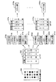
図2−1および図2−2は、サーバ14内の過去履歴格納部11に格納されるデータの作成方法を示す図である。過去履歴格納部11には、図2−1に示すように、過去のカラーパッチのLab座標における測定値(L、a、b)201が格納されている。過去のカラーパッチの測定値201は、特徴量変換部12内の第1のLUT202によって3次元のLab値201を1次元に圧縮されたベクトル値203として演算部10で演算され、過去履歴格納部11に格納される。第1のLUT202は予め用意されているテーブルであり、このテーブルが基準となるため、書き換えられることはない。前述のベクトル値203はパッチ生成時のLab値を決定する場合に用いる。
FIGS. 2-1 and 2-2 are diagrams illustrating a method of creating data stored in the past history storage unit 11 in the
ベクトルの情報圧縮時にベクトル量子化を用いる場合、代表ベクトルの数Bは、空間の分割回数(2分木における階層数)cを用いると2^c(^は羃乗を表す。以下、同様。)となり、また、(c−1)回分割した時の1次元ベクトル符号値2^(c−1)は、下位階層(c回分割した時)の1次元ベクトル符号値2^c−1と2^cの平均値を表す。よって、(c−1)回分割時のあるベクトル符号値2^(c−1)が青系の色を表現しているとすると、下位階層のベクトル符号値は、青緑系、もしくは青紫系の色を表現することになる。
When vector quantization is used at the time of vector information compression, the number B of representative vectors is 2 ^ c (^ represents a power) when the number of space divisions (the number of layers in a binary tree) c is used. ), And the one-dimensional
また、図2−2に示すように、出力されたカラーパッチ210を測定したLab値211と出力媒体の基準白色(例えば、紙白)のLab値との距離を求める。このとき、ΔE76の距離212はCIE1976Labの色差式に、ΔE94の距離213はCIE1994色差式に基づいて、各々計算される。さらに、ΔE76距離とΔE94距離の差(色差間距離と呼ぶ)214を求めることにより、対象とする色の特性を数値的に精細に捉えることができる。次に、特徴量変換部12内の第2の変換テーブルLUT215を用い、N次元の入力ベクトルを1次元のベクトル値216に変換する。このとき、入力のベクトルの次元数Nは、ΔE76距離212、ΔE94距離213、色差間距離214のみを結合する場合はN=3、また、Lab測定値211そのものとΔE76距離212、ΔE94距離213、色差間距離214を結合する場合はN=6となる。
距離 Further, as shown in FIG. 2-2, the distance between the
N次元から1次元へのデータの変換は、特徴量変換部12内の第1及び第2のLUT202,215により行なわれる。この第1及び第2のLUT202,215は、システム構築時に大量のサンプルデータを使用して作成されるもので、ある格子点値を表す符号とそれを代表するベクトル値が含まれている。入力、出力ともに、1次元の代表ベクトルの数は、プロファイル内で実装するN次元の立方体内の格子点数であり、ある表現色の分割数をnとした時、代表ベクトルの数はn^3となる。前述の第1のLUT202はプロファイル生成時にも使用するためn^3とするが、第2のLUT215はサーバ14の負荷の軽減を図るため、n^3よりも少ない数(例えば、(n/2)^3、(n/4)^3)で作成した代表ベクトルを用意するのが好ましい。また、第3のLUT217は、図3に示すように第1のLUT202によって代表色の近傍として表現された後のベクトルを用いることによって、LUT数の要素数を少なくした場合(N>L)においても、LUT217に示すようにL個の要素についてそれぞれベクトル値218a・・・218mを得ることにより高精度化を図ることができる。すなわち、代表色の近傍の格子点それぞれに対して第3のLUT217a・・・217mを用意しておき、前記図2(b)で示したように代表色近傍の全てについて前記処理を実行することなく、前記代表色の近傍の色に対応して前記処理211a,212a,213a,214a、・・・211m,212m,213m,214mのなどの処理を行い、これに対応するLUT217aないし217mのいずれかを使用して変換処理を行えばよいので、処理が軽くなり、高速処理が可能になる。また、色の範囲が絞られるので、より高精度の補正が可能になる。
The conversion of the data from N-dimensional to one-dimensional is performed by the first and
図4はカラーパッチ数・色域を最適化したカラーチャートを生成する手順を示すフローチャートである。 FIG. 4 is a flowchart showing a procedure for generating a color chart in which the number of color patches and the color gamut are optimized.
カラーパッチ数・色域を最適化したカラーチャートを生成する場合、図4に示すように、まず、プリンタ2よりパッチ数最適化の基準となるカラーチャートを出力し(ステップS1)、このカラーチャート内のカラーパッチ210のLab値を測定器5により測定する(ステップS2)。この時、カラーチャート内のパッチ数はLUT202内の代表ベクトルの数と同じか少ないものとする。次に、演算部10によってΔE76距離212、ΔE94距離213、色差間距離214を求め、ベクトルとして結合する(ステップS3)。
When generating a color chart in which the number of color patches and the color gamut are optimized, as shown in FIG. 4, first, a color chart serving as a reference for optimizing the number of patches is output from the printer 2 (step S1). The Lab value of the
ユーザから代表色(例えば、R、G、B、C、M、Y)のみ測定を行なうという指示が生じた場合(ステップS4−YES)、最も新しく測定した結果を過去履歴格納部11よりロードし、第3のLUT217a〜217mのいずれかから代表色を示す代表ベクトルに近い複数のデータを抽出する。
When the user instructs to measure only the representative colors (for example, R, G, B, C, M, and Y) (step S4-YES), the most recently measured result is loaded from the past history storage unit 11. , A plurality of data close to a representative vector indicating a representative color is extracted from any of the
抽出後、特徴量変換部12の第2のLUT215により、N次元のベクトルを1次元のベクトルに変換し、1次元のベクトルを過去履歴格納部11に格納する。ユーザからの指定がない場合は(ステップS4−NO)、最も新しく測定したプロファイルを構成する全色域に対応する全データに対して、特徴量変換部12の第2のLUT215によりN次元のベクトルを1次元のベクトルに変換し、1次元のベクトルを過去履歴格納部11に格納する。
After the extraction, the N-dimensional vector is converted into a one-dimensional vector by the
データ格納後、N次元のベクトルと代表ベクトル間の差を算出し、演算部10に送る。次に、前回のベクトル値を過去履歴格納部11より引き出し、カラーパッチ数を決定する。
After storing the data, the difference between the N-dimensional vector and the representative vector is calculated and sent to the
次回のカラーチャートに生成されるパッチの評価の段階としては2段階ある。第1段階では、前回と新規の測定結果のベクトル間の誤差(A1とする)と、測定値の平均的な値をあらわす代表ベクトルと新規の測定結果のベクトル間の誤差(A2とする)を比較する(ステップS5)。ここで、A1は前回と今回の測定値に基づく短期的なプリンタの特性を捉えた評価基準であり、A2は大量のサンプルの平均的な値と今回の測定値に基づく長期的なプリンタの特性を捉えた評価基準となる。A1<A2が成り立たなければ(ステップS5−NO)、前々回の結果を過去履歴格納部11よりロードし、新規測定結果との差(B1とする)を計算し、
Ev=αA1+(1−α)B1
を評価基準とする(ステップS6)。
There are two stages for evaluating the patches generated in the next color chart. In the first stage, an error between the vector of the previous measurement and the new measurement result (A1) and an error between the representative vector representing the average value of the measurement values and the vector of the new measurement result (A2) Compare (Step S5). Here, A1 is an evaluation criterion that captures short-term printer characteristics based on the previous and current measurement values, and A2 is a long-term printer characteristic based on the average value of a large number of samples and the current measurement values. It is an evaluation standard that captures If A1 <A2 does not hold (step S5-NO), the result of the previous measurement is loaded from the past history storage unit 11, and the difference from the new measurement result (B1) is calculated.
Ev = αA1 + (1−α) B1
Is used as an evaluation criterion (step S6).
また、A1<A2が成り立てば(ステップS5−YES)、代表ベクトルとの差が最も小さい測定値を過去履歴格納部11よりロードし、新規測定結果との差(B2とする)を計算し、
Ev=αA2+(1−α)B2
を評価基準とする(ステップS7)。
If A1 <A2 holds (step S5-YES), the measured value having the smallest difference from the representative vector is loaded from the past history storage unit 11, and the difference from the new measured result (referred to as B2) is calculated.
Ev = αA2 + (1−α) B2
Is set as an evaluation criterion (step S7).
係数αは通常0.5であるが、プリンタの状態により変更することができる。前回と今回の色域の条件が合わない場合(例えば、前回が全色域のパッチ、今回が代表色域のパッチ)は、今回の条件を優先し、不足分のデータは、過去履歴格納部11より抽出することによって誤差を求める。 The coefficient α is usually 0.5, but can be changed according to the state of the printer. If the previous and current color gamut conditions do not match (for example, the previous is the entire color gamut patch and the current is the representative color gamut patch), the current condition is given priority, and the missing data is stored in the past history storage unit. An error is obtained by extracting the error.
評価基準であるEvがパッチ出力判定の閾値θ1より大きい(Ev>θ1)場合のみ、対象となるLab値をパッチ生成用として保持する(ステップS8)。閾値判定処理終了後、パッチ生成用Lab値を第1のLUT201の逆参照より求め、Evの値に応じてLab値を変更し、カラーチャート内にランダムにパッチを生成し、配置した後、カラーチャートをプリンタ2より出力し、パッチの再測定を行う(ステップS8→ステップS1)。このようにランダムにパッチを生成し、配置することにより、カラーパッチの色と配置位置が任意に変更され、その変更された位置に作成されたカラーパッチを測定することになるので、経時的変化に対応することが可能になる。従来のようにカラーパッチの配置が固定されていた場合には、カラーパッチを形成していない個所の経時的変化に対応できなくなっていたが、このように処理することにより、経時的変化が問題になることはない。なお、前記カラーパッチ形成位置は、Ev値が小さいときは感光体のより端部側に、大きいときはより中央部側に設定する。これにより、Ev値に応じてカラーパッチの形成位置が設定され、前記カラーパッチ数の変更と組み合わせ得ることにより、経時的変換に高精度に対応することができる。
Only when the evaluation reference Ev is greater than the patch output determination threshold θ1 (Ev> θ1), the target Lab value is held for patch generation (step S8). After the threshold value determination processing, the Lab value for patch generation is obtained by dereferencing the
なお、カラーパッチの数を変更する場合にも、カラーパッチの形成位置が変更されるので、Ev値に基づいて変更しない場合にも、経時的変化への対応は可能となる。 (4) Since the formation position of the color patches is changed even when the number of the color patches is changed, it is possible to cope with a temporal change even when the color patches are not changed based on the Ev value.
そして、パッチ数がパッチ数の閾値θ2より小さくなった時点で(ステップS9)、作成するパッチ数を決定する。パッチ測定・生成処理終了後、前述の評価基準値Evを重みとして、プロファイル生成部がプロファイルを作成する。なお、前記閾値θ2は、ユーザが設定するか、パッチ出力判定の閾値θ1に基づいて設定される。 {Circle around (5)} When the number of patches becomes smaller than the threshold value θ2 of the number of patches (step S9), the number of patches to be created is determined. After the patch measurement / generation processing ends, the profile generation unit creates a profile using the above-described evaluation reference value Ev as a weight. The threshold θ2 is set by the user or is set based on a threshold θ1 for patch output determination.
なお、前述の実施形態では、図1に示すようにサーバ14とクライアント13とプリンタ2とにより画像処理システムが構成されているが、図5に示すように、プロファイル更新部515、演算部510、特徴量変換部512、プロファイル格納部506、過去履歴格納部511および印刷を実行するプリンタエンジン502を1つの装置として構成し、あるいは1つの筐体内にそれぞれ収納して1つのプリンタ500(画像形成装置)と構成してすることも可能である。この場合、プロファイル更新部515、演算部510、特徴量変換部512、プリファイル格納部506、過去履歴格納部511は、図1に示した各部と同様の機能を有する。
In the above-described embodiment, the image processing system includes the
また、図6に示すように、PC613のプリンタドライバ608に、プロファイル更新部615、演算部610、特徴量変換部612を、さらにプロファイル格納部606、過去履歴格納部611をHDDまたは不揮発性メモリに設けることも可能である。
As shown in FIG. 6, the
以上のように、本実施形態によれば、過去の履歴情報・代表ベクトルと新規情報を基に情報圧縮時の誤差を求め、評価基準とすることによって、カラーチャートのパッチ数を制御し、プリンタの短期的な特性(カラーパッチの位置を数を検出することにより得られる特性)と長期的な特性(過去履歴格納に格納された履歴情報)を捉えたプリンタプロファイルを高精度に生成することができる。また、Lab距離を基準とした色域の分割を行なうことにより、定量的な代表色の選択を行なうことができ、ユーザの用途に応じたプロファイル作成・修正を行なうことができる。 As described above, according to the present embodiment, the error at the time of information compression is obtained based on the past history information / representative vector and the new information, and is used as an evaluation criterion to control the number of patches in the color chart. It is possible to generate a printer profile that captures short-term characteristics (characteristics obtained by detecting the number of positions of color patches) and long-term characteristics (history information stored in past history storage) with high accuracy. it can. Further, by performing the color gamut division based on the Lab distance, a quantitative representative color can be selected, and a profile can be created and modified according to the user's purpose.
なお、前記図4に示した手順をコンピュータプログラムとして提供することができる。 The procedure shown in FIG. 4 can be provided as a computer program.
以上のように、本発明にかかる画像処理装置、画像処理システム、画像形成装置、画像処理方法及びプログラムは、画像処理を実行するPC、ワークステーション、プリンタ装置およびプリンタ機能を有する複合機に適している。 As described above, the image processing apparatus, the image processing system, the image forming apparatus, the image processing method, and the program according to the present invention are suitable for a PC that executes image processing, a workstation, a printer, and a multifunction peripheral having a printer function. I have.
1 画像処理装置
2,500 プリンタ
3 モニタ
4 オペレータ(操作部)
5,505 測定器
6,506,606 プロファイル格納部
7 アプリケーション
8 プリンタドライバ
9,16 OS
10,510,610 演算部
11,511,611 過去履歴格納部
12,512,612 特徴量変換部
13 クライアント
14 サーバ
15,515,615 プロファイル更新部
17 ネットワーク
201 カラーパッチの測定値
202 第1のLUT
203,216,218a・・・218m ベクトル値
210 カラーパッチ
211 測定Lab値
212 Δ76色差
213 Δ94色差
214 色差間距離
215 第2のLUT
217a・・・217m 第3のLUT
503 操作パネル
613 PC
1 image processing device 2,500
5,505 Measuring instrument 6,506,606
10, 510, 610
203, 216, 218a...
217a ... 217m Third LUT
503
Claims (31)
入力されたデータの色変換を行う色変換手段と、
前記カラーチャートの測定値の変換値を含む前記カラーチャートの測定に関する過去の履歴情報を格納する格納手段と、
前記格納手段に格納された履歴情報と、入力された新規なカラーチャートの測定に関する情報とを比較し、その比較結果に基づいてカラーパッチ数を決定する演算手段と、
前記演算手段によって決定されたパッチ数のカラーチャートを出力させて再度読み込み、プリンタプロファイルを更新する更新手段と、
を備えたことを特徴とする画像処理装置。 An image processing apparatus that updates a printer profile based on data obtained by reading a color chart output to one medium,
Color conversion means for performing color conversion of input data;
Storage means for storing past history information related to the measurement of the color chart including the conversion value of the measurement value of the color chart,
Arithmetic means for comparing the history information stored in the storage means with the information on the measurement of the input new color chart, and determining the number of color patches based on the comparison result;
Update means for outputting and re-reading the color chart of the number of patches determined by the arithmetic means, and updating the printer profile,
An image processing apparatus comprising:
前記カラーパッチを測定したLab値と出力媒体の基準白色のLab値のΔE76に基づく距離、
前記カラーパッチを測定したLab値と出力媒体の基準白色のLab値のΔE94に基づく距離、
及び前記両距離の差で表される色差間距離
を結合した値であることを特徴とする請求項4に記載の画像処理装置。 The evaluation criterion for setting the number of the output patches is based on the Lab value obtained for each color gamut forming the profile and the measured Lab value of the color patch and ΔE76 of the Lab value of the reference white of the output medium. distance,
A distance based on ΔE94 of the Lab value of the color patch and the Lab value of the reference white of the output medium,
The image processing apparatus according to claim 4, wherein the value is a value obtained by combining a color difference distance represented by a difference between the two distances.
前記カラーパッチを測定したLab値と出力媒体の基準白色のLab値のΔE76に基づく距離、
前記カラーパッチを測定したLab値と出力媒体の基準白色のLab値のΔE94に基づく距離、
及び前記両距離の差で表される色差間距離
を結合した値であることを特徴とする請求項4に記載の画像処理装置。 The evaluation criterion for setting the number of output patches is determined for each neighborhood of a representative color consisting of preset colors constituting a profile. The Lab value measured for the color patch and the reference white Lab of the output medium. Distance based on the value ΔE76,
A distance based on ΔE94 of the Lab value of the color patch and the Lab value of the reference white of the output medium,
The image processing apparatus according to claim 4, wherein the value is a value obtained by combining a color difference distance represented by a difference between the two distances.
前記圧縮手段により圧縮された前記結合した値は、圧縮された値で保持されることを特徴とする請求項9または11に記載の画像処理装置。 The apparatus further includes a compression unit that compresses the combined value serving as a reference of the evaluation,
The image processing apparatus according to claim 9, wherein the combined value compressed by the compression unit is held as a compressed value.
前記サーバは、
入力されたデータの色変換を行う色変換手段と、
前記カラーチャートの測定値の変換値を含む前記カラーチャートの測定に関する過去の履歴情報を格納する格納手段と、
前記格納手段に格納された履歴情報と、入力された新規なカラーチャートの測定に関する情報とを比較し、その比較結果に基づいてカラーパッチ数を決定する演算手段と、
前記演算手段によって決定されたパッチ数のカラーチャートを出力させて再度読み込み、プリンタプロファイルを更新する更新手段と、を備え、
前記クライアントは、
前記サーバによって作成されたプリンタプロファイルを格納するプロファイル格納手段と、
アプリケーションから受け取った入力色データを、画像形成装置が解釈可能な形式のデータに変換するプリンタドライバと、
を備えたことを特徴とする画像処理システム。 In an image processing system including a server and a client for updating a printer profile based on data obtained by reading a color chart output to one medium,
The server comprises:
Color conversion means for performing color conversion of input data;
Storage means for storing past history information related to the measurement of the color chart including the conversion value of the measurement value of the color chart,
Arithmetic means for comparing the history information stored in the storage means with the information on the measurement of the input new color chart, and determining the number of color patches based on the comparison result;
Updating means for outputting and re-reading the color chart of the number of patches determined by the arithmetic means, and updating the printer profile,
The client,
Profile storage means for storing a printer profile created by the server;
A printer driver that converts input color data received from the application into data in a format that can be interpreted by the image forming apparatus;
An image processing system comprising:
前記カラーチャートの測定値の変換値を含む前記カラーチャートの測定に関する過去の履歴情報を格納する格納手段と、
前記格納手段に格納された履歴情報と、入力された新規なカラーチャートの測定に関する情報とを比較し、その比較結果に基づいてカラーパッチ数を決定する演算手段と、
前記演算手段によって決定されたパッチ数のカラーチャートを出力させて再度読み込み、プリンタプロファイルを更新する更新手段と、
媒体に可視画像を形成する画像形成手段と、
を備えたことを特徴とする画像形成装置。 Color conversion means for performing color conversion of input data;
Storage means for storing past history information related to the measurement of the color chart including the conversion value of the measurement value of the color chart,
Arithmetic means for comparing the history information stored in the storage means with the information on the measurement of the input new color chart, and determining the number of color patches based on the comparison result;
Update means for outputting and re-reading the color chart of the number of patches determined by the arithmetic means, and updating the printer profile,
Image forming means for forming a visible image on a medium,
An image forming apparatus comprising:
入力されたデータの色変換を行う色変換工程と、
前記カラーチャートの測定値の変換値を含む前記カラーチャートの測定に関する過去の履歴情報を格納手段に格納する格納工程と、
前記格納手段に格納された履歴情報と、入力された新規なカラーチャートの測定に関する情報とを比較し、その比較結果に基づいてカラーパッチ数を決定する演算工程と、
前記演算工程によって決定されたパッチ数のカラーチャートを出力させて再度読み込み、プリンタプロファイルを更新する更新工程と、
を含むことを特徴とする画像処理方法。 An image processing method for updating a printer profile based on data obtained by reading a color chart output for one medium, comprising:
A color conversion step of performing color conversion of input data;
A storing step of storing past history information related to measurement of the color chart including a conversion value of the measurement value of the color chart in a storage unit,
An operation step of comparing the history information stored in the storage unit with information on the measurement of the input new color chart, and determining the number of color patches based on the comparison result;
An update step of outputting and re-reading the color chart of the number of patches determined by the calculation step, and updating the printer profile,
An image processing method comprising:
前記カラーパッチを測定したLab値と出力媒体の基準白色のLab値のΔE76に基づく距離、
前記カラーパッチを測定したLab値と出力媒体の基準白色のLab値のΔE94に基づく距離、
及び前記両距離の差で表される色差間距離
を結合した値であることを特徴とする請求項23に記載の画像処理方法。 The evaluation criterion for setting the number of the output patches is based on the Lab value obtained for each color gamut forming the profile and the measured Lab value of the color patch and ΔE76 of the Lab value of the reference white of the output medium. distance,
A distance based on ΔE94 of the Lab value of the color patch and the Lab value of the reference white of the output medium,
The image processing method according to claim 23, wherein the value is a value obtained by combining a color difference distance represented by a difference between the two distances.
前記カラーパッチを測定したLab値と出力媒体の基準白色のLab値のΔE76に基づく距離、
前記カラーパッチを測定したLab値と出力媒体の基準白色のLab値のΔE94に基づく距離、
及び前記両距離の差で表される色差間距離
を結合した値であることを特徴とする請求項23に記載の画像処理方法。 The evaluation criterion for setting the number of output patches is determined for each neighborhood of a representative color consisting of preset colors constituting a profile. The Lab value measured for the color patch and the reference white Lab of the output medium. Distance based on the value ΔE76,
A distance based on ΔE94 of the Lab value of the color patch and the Lab value of the reference white of the output medium,
The image processing method according to claim 23, wherein the value is a value obtained by combining a color difference distance represented by a difference between the two distances.
前記圧縮工程により圧縮された前記結合した値は、圧縮された値で保持されることを特徴とする請求項26または28に記載の画像処理方法。 Further comprising a compression step of compressing the combined value serving as a reference of the evaluation,
29. The image processing method according to claim 26, wherein the combined value compressed in the compression step is held as a compressed value.
入力されたデータの色変換を行う色変換手順と、
前記カラーチャートの測定値の変換値を含む前記カラーチャートの測定に関する過去の履歴情報を格納手段に格納する格納手順と、
前記格納手段に格納された履歴情報と、入力された新規なカラーチャートの測定に関する情報とを比較し、その比較結果に基づいてカラーパッチ数を決定する演算手順と、
前記演算手順によって決定されたパッチ数のカラーチャートを出力させて再度読み込み、プリンタプロファイルを更新する更新手順と、
をコンピュータに実行させるプログラム。 In a program for updating a printer profile based on data obtained by reading a color chart output to one medium,
A color conversion procedure for performing color conversion of input data;
A storing procedure for storing in the storage means past history information related to the measurement of the color chart including the conversion value of the measurement value of the color chart,
An arithmetic procedure for comparing the history information stored in the storage unit with the information on the measurement of the input new color chart, and determining the number of color patches based on the comparison result;
An update procedure for outputting and re-reading the color chart of the number of patches determined by the calculation procedure and updating the printer profile,
A program that causes a computer to execute.
Priority Applications (3)
| Application Number | Priority Date | Filing Date | Title |
|---|---|---|---|
| JP2003317404A JP2004135312A (en) | 2002-09-20 | 2003-09-09 | Image processor, image processing system, image forming apparatus, image processing method, and program |
| US10/662,667 US7403305B2 (en) | 2002-09-20 | 2003-09-15 | Image processing system, apparatus and method for updating a printer profile based on comparison of previous and current measurements of color chart |
| EP03255893A EP1401192A3 (en) | 2002-09-20 | 2003-09-19 | Creating and updating a printer profile |
Applications Claiming Priority (2)
| Application Number | Priority Date | Filing Date | Title |
|---|---|---|---|
| JP2002275934 | 2002-09-20 | ||
| JP2003317404A JP2004135312A (en) | 2002-09-20 | 2003-09-09 | Image processor, image processing system, image forming apparatus, image processing method, and program |
Publications (1)
| Publication Number | Publication Date |
|---|---|
| JP2004135312A true JP2004135312A (en) | 2004-04-30 |
Family
ID=31949606
Family Applications (1)
| Application Number | Title | Priority Date | Filing Date |
|---|---|---|---|
| JP2003317404A Pending JP2004135312A (en) | 2002-09-20 | 2003-09-09 | Image processor, image processing system, image forming apparatus, image processing method, and program |
Country Status (3)
| Country | Link |
|---|---|
| US (1) | US7403305B2 (en) |
| EP (1) | EP1401192A3 (en) |
| JP (1) | JP2004135312A (en) |
Cited By (5)
| Publication number | Priority date | Publication date | Assignee | Title |
|---|---|---|---|---|
| JP2009194553A (en) * | 2008-02-13 | 2009-08-27 | Seiko Epson Corp | Method of determining number of patches |
| JP2009194552A (en) * | 2008-02-13 | 2009-08-27 | Seiko Epson Corp | Method of determining number of patches, calibration method and printer |
| US20150070512A1 (en) * | 2013-09-06 | 2015-03-12 | Ferrand D.E. Corley | Test pattern and method of monitoring changes in test pattern characteristics |
| EP4178190A1 (en) | 2021-11-08 | 2023-05-10 | Ricoh Company, Ltd. | Information processing apparatus, image forming system, method for controlling display, and carrier medium |
| EP4178192A1 (en) | 2021-11-09 | 2023-05-10 | Ricoh Company, Ltd. | Information processing apparatus, image forming system, information processing method, and carrier medium |
Families Citing this family (13)
| Publication number | Priority date | Publication date | Assignee | Title |
|---|---|---|---|---|
| DE10246253A1 (en) * | 2002-10-02 | 2004-04-22 | Cgs Publishing Technologies International Gmbh | Method for creating a color match between a target object and a source object |
| JP4059873B2 (en) * | 2004-09-22 | 2008-03-12 | シャープ株式会社 | Image processing device |
| US7310107B2 (en) * | 2005-03-22 | 2007-12-18 | Eastman Kodak Company | Method for monitoring image calibration |
| JP5132428B2 (en) * | 2008-05-28 | 2013-01-30 | キヤノン株式会社 | Information processing apparatus, method, and program |
| JP5257615B2 (en) * | 2009-06-04 | 2013-08-07 | 株式会社リコー | Color conversion table generation apparatus, color conversion table generation method, and image processing apparatus |
| JP2011077844A (en) * | 2009-09-30 | 2011-04-14 | Seiko Epson Corp | Printing apparatus, and calibration method |
| DE102009046594A1 (en) * | 2009-11-10 | 2011-05-12 | Manroland Ag | Method for controlling a printing process |
| JP5909928B2 (en) | 2010-09-16 | 2016-04-27 | 株式会社リコー | Image forming apparatus, image forming method, and program |
| US8576418B2 (en) * | 2010-12-13 | 2013-11-05 | Xerox Corporation | Method for dynamic optimization of refinement patches for color printer characterization |
| JP5948737B2 (en) | 2011-05-30 | 2016-07-06 | 株式会社リコー | Image processing apparatus, image processing method, and image processing program |
| JP6098587B2 (en) * | 2014-08-06 | 2017-03-22 | コニカミノルタ株式会社 | Printing control apparatus, printing system, color adjustment control program, and color adjustment control method |
| US9686445B2 (en) * | 2015-09-30 | 2017-06-20 | Konica Minolta Laboratory U.S.A., Inc. | Method and system for dynamically producing color validation patches |
| JP2023020463A (en) * | 2021-07-30 | 2023-02-09 | 株式会社リコー | Image forming apparatus, program, and image forming method |
Family Cites Families (15)
| Publication number | Priority date | Publication date | Assignee | Title |
|---|---|---|---|---|
| US5107332A (en) * | 1989-05-17 | 1992-04-21 | Hewlett-Packard Company | Method and system for providing closed loop color control between a scanned color image and the output of a color printer |
| US5781206A (en) * | 1995-05-01 | 1998-07-14 | Minnesota Mining And Manufacturing Company | Apparatus and method for recalibrating a multi-color imaging system |
| US5739927A (en) * | 1995-06-07 | 1998-04-14 | Xerox Corporation | Method for refining an existing printer calibration using a small number of measurements |
| JP3869925B2 (en) * | 1997-01-31 | 2007-01-17 | キヤノン株式会社 | Image processing apparatus and method |
| US6178007B1 (en) * | 1997-01-21 | 2001-01-23 | Xerox Corporation | Method for continuous incremental color calibration for color document output terminals |
| US6048117A (en) * | 1998-05-08 | 2000-04-11 | Xerox Corporation | Network-based system for color calibration of printers |
| JP2000004369A (en) | 1998-06-15 | 2000-01-07 | Ricoh Co Ltd | Method and processor for image processing, and recording medium thereof |
| US6870636B2 (en) * | 1998-11-20 | 2005-03-22 | Canon Kabushiki Kaisha | Determining color mappings for a color printer |
| US6233061B1 (en) * | 1999-02-11 | 2001-05-15 | Lexmark International, Inc. | Ink reduction device and method for a color inkjet printer |
| JP2000318266A (en) * | 1999-05-12 | 2000-11-21 | Canon Inc | Calibration method, information processor and information processing system |
| JP2001045313A (en) | 1999-07-30 | 2001-02-16 | Fuji Photo Film Co Ltd | Method and device for converting color, color conversion program storage medium and method for correcting color |
| JP3910323B2 (en) | 1999-11-11 | 2007-04-25 | 富士フイルム株式会社 | Profile creation method and profile creation apparatus |
| US7064860B1 (en) * | 2000-05-15 | 2006-06-20 | Xerox Corporation | Color-balanced TRC correction to compensate for illuminant changes in printer characterization |
| US7003151B2 (en) * | 2000-07-19 | 2006-02-21 | Canon Kabushiki Kaisha | Image processing apparatus and control method therefor |
| JP2002187314A (en) * | 2000-09-12 | 2002-07-02 | Canon Inc | Image processor, method therefor, method of predicting, method of displaying and method of managing |
-
2003
- 2003-09-09 JP JP2003317404A patent/JP2004135312A/en active Pending
- 2003-09-15 US US10/662,667 patent/US7403305B2/en not_active Expired - Fee Related
- 2003-09-19 EP EP03255893A patent/EP1401192A3/en not_active Withdrawn
Cited By (7)
| Publication number | Priority date | Publication date | Assignee | Title |
|---|---|---|---|---|
| JP2009194553A (en) * | 2008-02-13 | 2009-08-27 | Seiko Epson Corp | Method of determining number of patches |
| JP2009194552A (en) * | 2008-02-13 | 2009-08-27 | Seiko Epson Corp | Method of determining number of patches, calibration method and printer |
| US20150070512A1 (en) * | 2013-09-06 | 2015-03-12 | Ferrand D.E. Corley | Test pattern and method of monitoring changes in test pattern characteristics |
| EP4178190A1 (en) | 2021-11-08 | 2023-05-10 | Ricoh Company, Ltd. | Information processing apparatus, image forming system, method for controlling display, and carrier medium |
| US11895285B2 (en) | 2021-11-08 | 2024-02-06 | Ricoh Company, Ltd. | Information processing apparatus, image forming system, method for controlling display, and non-transitory recording medium |
| EP4178192A1 (en) | 2021-11-09 | 2023-05-10 | Ricoh Company, Ltd. | Information processing apparatus, image forming system, information processing method, and carrier medium |
| US11899989B2 (en) | 2021-11-09 | 2024-02-13 | Ricoh Company, Ltd. | Information processing apparatus, image forming system, information processing method, and non-transitory recording medium for monitoring color matching processing |
Also Published As
| Publication number | Publication date |
|---|---|
| EP1401192A2 (en) | 2004-03-24 |
| US20040114165A1 (en) | 2004-06-17 |
| US7403305B2 (en) | 2008-07-22 |
| EP1401192A3 (en) | 2005-10-05 |
Similar Documents
| Publication | Publication Date | Title |
|---|---|---|
| JP2004135312A (en) | Image processor, image processing system, image forming apparatus, image processing method, and program | |
| US7035454B2 (en) | Image processing method and apparatus, and profile management method | |
| JP4623137B2 (en) | Color processing apparatus, method and program | |
| JP4692564B2 (en) | Color processing apparatus and program | |
| US7054033B2 (en) | Image processing method, image processing apparatus, and storage medium | |
| US7616361B2 (en) | Color processing apparatus and its method | |
| JP2007163979A (en) | Profile preparation apparatus, profile preparation program and image output apparatus | |
| EP1968305B1 (en) | Color processing apparatus and method thereof | |
| JP4164214B2 (en) | Color processing apparatus and method | |
| US20080137941A1 (en) | Constructing basis functions using sensor wavelength dependence | |
| JP4553259B2 (en) | Image processing apparatus, image processing method, program, and recording medium | |
| US7397582B2 (en) | Color characterization with enhanced purity | |
| JP3990859B2 (en) | Color processing method and apparatus | |
| JP4838699B2 (en) | Color processing apparatus and method | |
| JP2002142124A (en) | Profile creating device, method therefor and profile creating program storing medium | |
| JP2009278264A (en) | Color processing apparatus, and program | |
| JP4979819B2 (en) | Color processing apparatus and method | |
| JP4645666B2 (en) | Color processing apparatus and program | |
| JP2008067308A (en) | Color processing device, color processing method, and program | |
| JP4401853B2 (en) | Image processing apparatus and method | |
| JP4379009B2 (en) | Method for creating input profile and computer program | |
| US8437541B2 (en) | Color correction coefficient generating apparatus, color correction coefficient generation method, and computer readable medium storing program | |
| JP2009284107A (en) | Color processing apparatus and program | |
| JP2004147171A (en) | Image processor | |
| JP6729098B2 (en) | Color processing device, color processing system, and color processing program |
Legal Events
| Date | Code | Title | Description |
|---|---|---|---|
| A621 | Written request for application examination |
Free format text: JAPANESE INTERMEDIATE CODE: A621 Effective date: 20040224 |
|
| A977 | Report on retrieval |
Free format text: JAPANESE INTERMEDIATE CODE: A971007 Effective date: 20050930 |
|
| A131 | Notification of reasons for refusal |
Free format text: JAPANESE INTERMEDIATE CODE: A131 Effective date: 20051220 |
|
| A02 | Decision of refusal |
Free format text: JAPANESE INTERMEDIATE CODE: A02 Effective date: 20060502 |