JP2004132575A - Cooling device - Google Patents
Cooling device Download PDFInfo
- Publication number
- JP2004132575A JP2004132575A JP2002296038A JP2002296038A JP2004132575A JP 2004132575 A JP2004132575 A JP 2004132575A JP 2002296038 A JP2002296038 A JP 2002296038A JP 2002296038 A JP2002296038 A JP 2002296038A JP 2004132575 A JP2004132575 A JP 2004132575A
- Authority
- JP
- Japan
- Prior art keywords
- refrigerant
- circulation circuit
- cooler
- cooling device
- compressor
- Prior art date
- Legal status (The legal status is an assumption and is not a legal conclusion. Google has not performed a legal analysis and makes no representation as to the accuracy of the status listed.)
- Pending
Links
Images
Landscapes
- Devices That Are Associated With Refrigeration Equipment (AREA)
Abstract
Description
【0001】
【発明の属する技術分野】
この発明は、冷却装置、特に圧縮機と凝縮器と絞り装置と蒸発器とを順次冷媒配管で接続し、冷媒を強制循環させて上記蒸発器で冷却する冷媒強制循環回路及び放熱器と冷却器とを冷媒配管で接続し、温度差によって冷媒を循環させて上記冷却器で冷却する冷媒自然循環回路を有する冷却装置に関するものである。
【0002】
【従来の技術】
従来のこの種の冷却装置は、冷媒自然循環回路の冷却器と、冷媒強制循環回路の蒸発器とを共通風路内に設置して、発熱機器を収容する筐体内の上部に設置すると共に、冷媒強制循環回路の蒸発器と接続される圧縮機、凝縮器、絞り装置を筐体外に位置する室外機に設置し、冷媒自然循環回路の冷却器と接続される放熱器は筐体外で、かつ筐体の上部に冷媒強制循環回路の室外機とは別に設置していた。
【0003】
冷媒自然循環回路は、冷却器の冷媒が筐体内の発熱機器によって加熱された空気と熱交換してガス冷媒となり、外部の放熱器へ移動し、ここで外気と熱交換して凝縮し液冷媒となる。この液冷媒がガス冷媒との密度差による自然循環によって再び冷却器へ戻る動作を繰り返し筐体内を冷却する。
一方、冷媒強制循環回路では、圧縮機から吐出された高温、高圧のガス冷媒が凝縮器で外気と熱交換することにより液冷媒となり、更に絞り装置で減圧されて気液二相状態となり蒸発器に送られる。ここで冷媒自然循環回路の冷却器によって予備冷却されていた空気と熱交換して低圧のガス冷媒となり圧縮機に戻る動作を繰り返す。(例えば特許文献1参照)
【0004】
【特許文献1】
特開2001−99446号公報(段落0032−0035、図1)
【0005】
【発明が解決しようとする課題】
従来の冷却装置は以上のように構成され、冷媒強制循環回路の圧縮機、凝縮器、絞り装置等は筐体外部に設置され、冷媒自然循環回路の放熱器は筐体上方の外面に設けられ、更に、冷媒強制循環回路の蒸発器と冷媒自然循環回路の冷却器は筐体内部の上方に設けられる構成であったため、構造が複雑で、多くの設置スペースを必要とし、また、組み立てに手間を要し、価格も高くなるという問題点があった。
【0006】
この発明は、上記のような問題点を解決するためになされたもので、構造をコンパクトにして全体をユニット化することができ、組み立てが容易で、消費電力も削減することが可能であり、原価低減も図ることができる冷却装置を提供することを目的とする。
【0007】
【課題を解決するための手段】
この発明に係る冷却装置は、圧縮機と凝縮器と絞り装置と蒸発器とを順次冷媒配管で接続し、冷媒を圧縮機によって循環させて上記蒸発器で冷却する冷媒強制循環回路及び放熱器と冷却器とを冷媒配管で接続し、冷媒を温度差によって循環させて上記冷却器で冷却する冷媒自然循環回路を単一の支持体に装着してユニット化したものである。
【0008】
【発明の実施の形態】
実施の形態1.
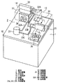
以下、この発明の実施の形態1を図にもとづいて説明する。図1は、実施の形態1の概略構成を示す斜視図、図2は、支持体を斜め下方から見た状態を示す斜視図である。これらの図において、被冷却装置は発熱機器(図示せず)を収納した密閉された筐体1であり、冷却装置2は冷媒強制循環回路を構成する要素(詳細後述)と冷媒自然循環回路を構成する要素(詳細後述)とを単一の支持体10に装着してユニット化したものを筐体1の上部外面に設置する形で構成されている。なお、筐体1は密閉された部屋等の所定空間であってもよい。
【0009】
支持体10上に装着される冷媒強制循環回路は、圧縮機21と、この圧縮機に冷媒配管22Aを介して接続された凝縮器23と、この凝縮器に設けられた送風機24と、上記凝縮器23に冷媒配管22Bを介して接続された絞り装置(図示せず)と、この絞り装置に別の冷媒配管(図示せず)を介して接続されると共に、冷媒配管22Cによって圧縮機21に接続された蒸発器25と、この蒸発器に設けられた送風機26とから構成され、冷媒自然循環回路は、上記蒸発器25の近辺に設けられた冷却器31と、この冷却器に冷媒配管32A、32Bを介して接続されると共に、上記凝縮器23の上部に配設され、上記冷却器31より高い位置に設置された放熱器33とから構成されている。
放熱器33に対する送風は、送風機24を凝縮器23と放熱器33との中間位置に配設することにより共用する形で行なわれている。
【0010】
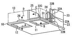
なお、冷媒自然循環回路の冷却器31を設けた部分の支持体10には、図2に示すように、表裏に貫通する孔部11を形成し、冷媒強制循環回路の送風機26を設けた部分の支持体10にも、図2に示すように、表裏に貫通する孔部12を形成すると共に、支持体10の上面に冷却器31と蒸発器25と送風機26を覆うカバーを設け、これら三者に共通の風路13を形成している。
送風機26が図2の矢印A方向に送風すると共通風路13に対して吸い出し送風機として機能し、筐体1内で発熱機器(図示せず)から排出された熱気を孔部11から矢印Bのように共通風路13に吸い込み、図1の矢印C、Dで示すように、共通風路13内の冷却器31、蒸発器25を経て冷却した後、送風機26から矢印Aのように再び筐体1内に送り込まれる。
なお、送風機26を共通風路の吸い込み側に設けて押し込み送風機として機能させることもできる。
【0011】
この場合、筐体内外の温度差と、冷却器31及び放熱器33の高低差によって冷媒配管32A、32B内の冷媒が自然循環し、常時、冷却機能を有する冷媒自然循環回路の冷却器31が共通風路13の上流側に位置するため、予備冷却装置として機能し、冷媒強制循環回路の蒸発器25は、冷却器31によって予備冷却された空気を冷却することになるため、冷媒強制循環回路の効率が向上する。
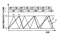
図3は、冷媒強制循環回路と冷媒自然循環回路とを併用した場合と併用しなかった場合の冷媒強制循環回路の運転パターンを示す説明図で、縦軸は筐体または所定空間の温度であり、T1は筐体内を冷却することによって維持すべき最低温度、T2は筐体内で許容される最高温度で、例えば35℃である。
【0012】
また、xは冷媒強制循環回路のみによって筐体内を冷却した場合の冷媒強制循環回路の圧縮機の運転パターン、Xはそれに対応する温度変化、yは冷媒強制循環回路と冷媒自然循環回路とを併用し、上述のように、冷媒自然循環回路による予備冷却が行なわれた場合の、冷媒強制循環回路の圧縮機の運転パターン、Yはそれに対応する温度変化を示すものである。
冷媒強制循環回路のみによって筐体内を冷却する場合は、筐体内温度がT1になるまで圧縮機を運転して冷却し、温度がT1に達した時点で圧縮機が停止されるため、筐体内温度が上昇する。筐体内温度がT2に達した時点X1で再び圧縮機が運転されて温度T1まで冷却され、以後、同様な運転、停止を繰り返して筐体内温度がT2とT1の範囲に保たれることになる。また、冷媒自然循環回路と冷媒強制循環回路とを併用した場合には、上述のように、冷媒自然循環回路の冷却器が共通風路13の上流側、即ち吸い込み側に配設されて予備冷却を行なうため、図3にYで示すように、Y1で圧縮機が運転されると、温度変化XよりもT1に早く達し、圧縮機運転が停止される。この後、徐々にT2に向かって温度が上昇するが、その上昇の勾配は冷媒自然循環回路の運転が常時行なわれているため、温度変化Xと比較して緩やかになる。温度がT2に達すると圧縮機が運転されて温度がT1になるまで継続され、以後、この運転パターンを繰り返す。
なお、筐体内温度、外気温度により温度上昇の勾配は異なる。また、冬期のように外気温度が筐体内温度より低く、その差が大きい場合は冷媒自然循環回路運転による冷却能力も大きくなり、冷媒自然循環回路の運転のみで冷却可能な場合もある。このときは、圧縮機は全く運転されることなく冷却が行なわれる。
【0013】
この運転パターンからも明らかなように、冷媒強制循環回路と冷媒自然循環回路とを併用した場合には、冷媒強制循環回路の圧縮機の停止時間が長くなり消費電力の削減が図れる他、機器の寿命にも影響し、全体的な効率を向上させることができる。また、冷媒自然循環回路は、筐体内外の温度差が大きいほど、冷却度が大になるため、温度差が大きい場合には、冷媒強制循環回路の圧縮機の停止時間も長くなり、効率が更に向上することになる。一方、冷媒強制循環回路の凝縮器23と冷媒自然循環回路の放熱器33は、凝縮器23を下側にして上下に重ねる形で配設し、放熱器33の設置位置を冷却器31より高くすることにより、冷媒自然循環回路の冷却度を大きくして効率の向上を図るのに加え、設置スペースの削減を図っている。また、凝縮器23と放熱器33に対して送風機24を共通に使用することにより原価低減を図り、更に、これら全体をカバーで覆って風路14を形成することにより、共通の送風機24で効率よく冷却ができるようにしている。
【0014】
【発明の効果】
この発明に係る冷却装置は、圧縮機と凝縮器と絞り装置と蒸発器とを順次冷媒配管で接続し、冷媒を圧縮機によって循環させて上記蒸発器で冷却する冷媒強制循環回路及び放熱器と冷却器とを冷媒配管で接続し、冷媒を温度差によって循環させて上記冷却器で冷却する冷媒自然循環回路の独立した2つの冷媒回路を単一の支持体に装着してユニット化したものであるため、装置全体をコンパクトに形成することができる他、組み立ても容易となるものである。
【図面の簡単な説明】
【図1】この発明の実施の形態1の概略構成を示す斜視図である。
【図2】実施の形態1の支持体を斜め下方から見た状態を示す斜視図である。
【図3】冷媒強制循環回路と冷媒自然循環回路とを併用した場合と併用しなかった場合の冷媒強制循環回路の運転パターン及び温度変化を示す説明図である。
【符号の説明】
1 筐体、 2 冷却装置、 10 支持体、 13 共通風路、 14 風路、 21 圧縮機、 22A、22B、22C 冷媒配管、 23 凝縮器、 24、26 送風機、 25 蒸発器、 31 冷却器、 32A、32B 冷媒配管、 33 放熱器。[0001]
TECHNICAL FIELD OF THE INVENTION
The present invention relates to a cooling device, in particular, a refrigerant forced circulation circuit, a radiator and a cooler, in which a compressor, a condenser, a throttle device, and an evaporator are sequentially connected by a refrigerant pipe, the refrigerant is forcibly circulated and cooled by the evaporator. The present invention relates to a cooling device having a refrigerant natural circulation circuit in which the refrigerant is connected by a refrigerant pipe, the refrigerant is circulated by a temperature difference, and is cooled by the cooler.
[0002]
[Prior art]
In this type of conventional cooling device, a cooler of a refrigerant natural circulation circuit and an evaporator of a refrigerant forced circulation circuit are installed in a common air passage, and installed at an upper portion in a housing for housing heat-generating devices, A compressor connected to the evaporator of the refrigerant forced circulation circuit, a condenser, a throttle device are installed in an outdoor unit located outside the housing, and a radiator connected to the cooler of the refrigerant natural circulation circuit is outside the housing, and It was installed in the upper part of the housing separately from the outdoor unit of the forced circulation circuit.
[0003]
In the refrigerant natural circulation circuit, the refrigerant in the cooler exchanges heat with the air heated by the heating device in the housing to become a gas refrigerant, moves to an external radiator, where it exchanges heat with the outside air and condenses into a liquid refrigerant. It becomes. The operation of returning the liquid refrigerant to the cooler again by natural circulation due to the difference in density with the gas refrigerant cools the inside of the housing.
On the other hand, in the refrigerant forced circulation circuit, the high-temperature, high-pressure gas refrigerant discharged from the compressor exchanges heat with the outside air in the condenser to become a liquid refrigerant, and is further decompressed by the expansion device to be in a gas-liquid two-phase state. Sent to Here, the operation of exchanging heat with the air that has been pre-cooled by the cooler of the refrigerant natural circulation circuit to become a low-pressure gas refrigerant and returning to the compressor is repeated. (For example, see Patent Document 1)
[0004]
[Patent Document 1]
JP 2001-99446 A (paragraphs 0032-0035, FIG. 1)
[0005]
[Problems to be solved by the invention]
The conventional cooling device is configured as described above, the compressor, the condenser, the throttle device, and the like of the refrigerant forced circulation circuit are installed outside the housing, and the radiator of the refrigerant natural circulation circuit is provided on the outer surface above the housing. Furthermore, since the evaporator of the refrigerant forced circulation circuit and the cooler of the refrigerant natural circulation circuit are provided above the inside of the housing, the structure is complicated, a large installation space is required, and the assembly is troublesome. , And the price is high.
[0006]
The present invention has been made in order to solve the above-described problems, and the structure can be made compact and the whole can be unitized, assembling is easy and power consumption can be reduced. It is an object of the present invention to provide a cooling device capable of reducing costs.
[0007]
[Means for Solving the Problems]
A cooling device according to the present invention includes a refrigerant forced circulation circuit and a radiator in which a compressor, a condenser, a throttle device, and an evaporator are sequentially connected by a refrigerant pipe, refrigerant is circulated by a compressor, and cooled by the evaporator. A cooler is connected to a cooler by a refrigerant pipe, and a refrigerant natural circulation circuit for circulating the refrigerant by a temperature difference and cooling by the cooler is mounted on a single support to form a unit.
[0008]
BEST MODE FOR CARRYING OUT THE INVENTION
Hereinafter, a first embodiment of the present invention will be described with reference to the drawings. FIG. 1 is a perspective view showing a schematic configuration of the first embodiment, and FIG. 2 is a perspective view showing a state where a support is viewed from obliquely below. In these figures, the device to be cooled is a sealed
[0009]
The refrigerant forced circulation circuit mounted on the
The ventilation to the
[0010]
In addition, as shown in FIG. 2, the
When the
It should be noted that the
[0011]
In this case, the refrigerant in the
FIG. 3 is an explanatory diagram showing an operation pattern of the forced refrigerant circulation circuit in a case where the refrigerant forced circulation circuit and the refrigerant natural circulation circuit are used in combination and in a case where the refrigerant forced circulation circuit is not used. The vertical axis indicates the temperature of the housing or the predetermined space. , T 1 is the lowest temperature, T 2 should be maintained by cooling the enclosure at the highest temperature allowed within the housing, for example, 35 ° C..
[0012]
In addition, x is the operation pattern of the compressor of the forced refrigerant circulation circuit when the inside of the casing is cooled only by the forced refrigerant circulation circuit, X is the corresponding temperature change, and y is both the refrigerant forced circulation circuit and the refrigerant natural circulation circuit. As described above, when the preliminary cooling is performed by the refrigerant natural circulation circuit, the operation pattern Y of the compressor of the refrigerant forced circulation circuit indicates a corresponding temperature change.
For the case of cooling the housing by only the refrigerant forced circulation circuit, which temperature in the case is cooled by operating the compressor until the T 1, the temperature is the compressor is stopped when it reaches T 1, housing Body temperature rises. Again compressor when X 1 to housing temperature reaches T 2 is operated is cooled to a temperature T 1, thereafter, the same operation, the coercive ranges enclosure temperature is T 2 and T 1 by repeating the stop You will be drowned. When the refrigerant natural circulation circuit and the refrigerant forced circulation circuit are used in combination, as described above, the cooler of the refrigerant natural circulation circuit is disposed on the upstream side of the
The gradient of the temperature rise differs depending on the temperature inside the housing and the outside air temperature. Further, when the outside air temperature is lower than the inside temperature of the housing and the difference is large as in winter, the cooling capacity by the operation of the natural refrigerant circuit is increased, and the cooling may be performed only by operating the natural refrigerant circuit. At this time, cooling is performed without operating the compressor at all.
[0013]
As is clear from this operation pattern, when the refrigerant forced circulation circuit and the refrigerant natural circulation circuit are used in combination, the stop time of the compressor in the refrigerant forced circulation circuit becomes longer, power consumption can be reduced, and equipment It also affects the service life and can improve overall efficiency. In addition, in the refrigerant natural circulation circuit, the degree of cooling increases as the temperature difference between the inside and the outside of the housing increases, and when the temperature difference is large, the stopping time of the compressor in the refrigerant forced circulation circuit also increases, and the efficiency increases. It will be further improved. On the other hand, the
[0014]
【The invention's effect】
A cooling device according to the present invention includes a refrigerant forced circulation circuit and a radiator in which a compressor, a condenser, a throttle device, and an evaporator are sequentially connected by a refrigerant pipe, refrigerant is circulated by a compressor, and cooled by the evaporator. A cooler is connected with a refrigerant pipe, and the refrigerant is circulated by a temperature difference, and two independent refrigerant circuits of a refrigerant natural circulation circuit for cooling by the cooler are mounted on a single support to form a unit. Therefore, not only can the entire apparatus be formed compact, but also the assembly can be facilitated.
[Brief description of the drawings]
FIG. 1 is a perspective view showing a schematic configuration of a first embodiment of the present invention.
FIG. 2 is a perspective view showing a state in which the support of the first embodiment is viewed obliquely from below.
FIG. 3 is an explanatory diagram showing an operation pattern and a temperature change of a refrigerant forced circulation circuit when a refrigerant forced circulation circuit and a refrigerant natural circulation circuit are used together and when they are not used together.
[Explanation of symbols]
Claims (5)
Priority Applications (1)
| Application Number | Priority Date | Filing Date | Title |
|---|---|---|---|
| JP2002296038A JP2004132575A (en) | 2002-10-09 | 2002-10-09 | Cooling device |
Applications Claiming Priority (1)
| Application Number | Priority Date | Filing Date | Title |
|---|---|---|---|
| JP2002296038A JP2004132575A (en) | 2002-10-09 | 2002-10-09 | Cooling device |
Publications (1)
| Publication Number | Publication Date |
|---|---|
| JP2004132575A true JP2004132575A (en) | 2004-04-30 |
Family
ID=32286125
Family Applications (1)
| Application Number | Title | Priority Date | Filing Date |
|---|---|---|---|
| JP2002296038A Pending JP2004132575A (en) | 2002-10-09 | 2002-10-09 | Cooling device |
Country Status (1)
| Country | Link |
|---|---|
| JP (1) | JP2004132575A (en) |
Cited By (2)
| Publication number | Priority date | Publication date | Assignee | Title |
|---|---|---|---|---|
| WO2012073746A1 (en) * | 2010-11-30 | 2012-06-07 | 富士電機株式会社 | Integrated air-conditioning system, and internal air unit, external air unit, and laminated body, thereof |
| WO2012090850A1 (en) * | 2010-12-28 | 2012-07-05 | 富士電機株式会社 | Outside air utilization air-conditioning system, and inside air unit, outside air unit and laminate thereof |
Citations (3)
| Publication number | Priority date | Publication date | Assignee | Title |
|---|---|---|---|---|
| JPH02233923A (en) * | 1989-03-06 | 1990-09-17 | Mitsui Ginkou:Kk | Central direct expansion air conditioning device |
| JPH03125889A (en) * | 1989-10-11 | 1991-05-29 | Sanyo Electric Co Ltd | Refrigerator |
| JP2001099446A (en) * | 1999-09-30 | 2001-04-13 | Mitsubishi Electric Corp | Air conditioning apparatus, and non-humidifying heating body-containing cooling equipment |
-
2002
- 2002-10-09 JP JP2002296038A patent/JP2004132575A/en active Pending
Patent Citations (3)
| Publication number | Priority date | Publication date | Assignee | Title |
|---|---|---|---|---|
| JPH02233923A (en) * | 1989-03-06 | 1990-09-17 | Mitsui Ginkou:Kk | Central direct expansion air conditioning device |
| JPH03125889A (en) * | 1989-10-11 | 1991-05-29 | Sanyo Electric Co Ltd | Refrigerator |
| JP2001099446A (en) * | 1999-09-30 | 2001-04-13 | Mitsubishi Electric Corp | Air conditioning apparatus, and non-humidifying heating body-containing cooling equipment |
Cited By (4)
| Publication number | Priority date | Publication date | Assignee | Title |
|---|---|---|---|---|
| WO2012073746A1 (en) * | 2010-11-30 | 2012-06-07 | 富士電機株式会社 | Integrated air-conditioning system, and internal air unit, external air unit, and laminated body, thereof |
| CN103140718A (en) * | 2010-11-30 | 2013-06-05 | 富士电机株式会社 | Integrated air-conditioning system, and internal air unit, external air unit, and laminated body, thereof |
| WO2012090850A1 (en) * | 2010-12-28 | 2012-07-05 | 富士電機株式会社 | Outside air utilization air-conditioning system, and inside air unit, outside air unit and laminate thereof |
| CN103261801A (en) * | 2010-12-28 | 2013-08-21 | 富士电机株式会社 | Outside air utilization air-conditioning system, and inside air unit, outside air unit and laminate thereof |
Similar Documents
| Publication | Publication Date | Title |
|---|---|---|
| RU2442209C2 (en) | The methods and devices of cooling | |
| JP3821153B2 (en) | Air conditioner outdoor unit | |
| KR100941604B1 (en) | Outdoor unit of air conditioner | |
| JP2014202398A (en) | Cooling system for air conditioner control box and air conditioner incorporating cooling system therein | |
| JP2006214635A (en) | Outdoor unit of air conditioner | |
| JP2006214633A (en) | Outdoor unit of air conditioner | |
| JPH05322224A (en) | Air conditioner | |
| EP3214380B1 (en) | Air conditioner | |
| JP2009002596A (en) | Cooling unit | |
| JP2004132575A (en) | Cooling device | |
| JP2017048960A (en) | Outdoor unit of air conditioner and air conditioner | |
| CN213367622U (en) | Frequency converter and refrigerating system | |
| TWM625973U (en) | Thermoelectric cooling chip cooling air conditioner | |
| JP2003097881A (en) | Refrigeration unit for container | |
| JP2004263986A (en) | Air conditioner | |
| JPH05118671A (en) | Electric component box of air conditioner | |
| JP4583230B2 (en) | Low temperature showcase | |
| KR100484661B1 (en) | Refrigerator increased with inner space | |
| KR101717378B1 (en) | Air conditioner using peltier module | |
| JP2007263431A (en) | Manufacturing method of transient critical refrigerating cycle apparatus | |
| KR100642772B1 (en) | Cooling System for Telecommunication Chamber | |
| JP2006343080A (en) | Refrigerator | |
| JP2010007986A (en) | Cooling device | |
| JP3326328B2 (en) | Heat exchanger | |
| JP2004205155A (en) | Heating element cooling system |
Legal Events
| Date | Code | Title | Description |
|---|---|---|---|
| A621 | Written request for application examination |
Free format text: JAPANESE INTERMEDIATE CODE: A621 Effective date: 20050705 |
|
| A977 | Report on retrieval |
Free format text: JAPANESE INTERMEDIATE CODE: A971007 Effective date: 20080219 |
|
| A131 | Notification of reasons for refusal |
Free format text: JAPANESE INTERMEDIATE CODE: A131 Effective date: 20080226 |
|
| A521 | Written amendment |
Free format text: JAPANESE INTERMEDIATE CODE: A523 Effective date: 20080326 |
|
| A02 | Decision of refusal |
Free format text: JAPANESE INTERMEDIATE CODE: A02 Effective date: 20080610 |