JP2004126028A - Collapsible mount type lens barrel - Google Patents
Collapsible mount type lens barrel Download PDFInfo
- Publication number
- JP2004126028A JP2004126028A JP2002287607A JP2002287607A JP2004126028A JP 2004126028 A JP2004126028 A JP 2004126028A JP 2002287607 A JP2002287607 A JP 2002287607A JP 2002287607 A JP2002287607 A JP 2002287607A JP 2004126028 A JP2004126028 A JP 2004126028A
- Authority
- JP
- Japan
- Prior art keywords
- frame
- lens
- group
- lens barrel
- optical axis
- Prior art date
- Legal status (The legal status is an assumption and is not a legal conclusion. Google has not performed a legal analysis and makes no representation as to the accuracy of the status listed.)
- Pending
Links
Images


Abstract
Description
【0001】
【発明の属する技術分野】
本発明は、像ぶれ補正装置を搭載した沈胴式レンズ鏡筒に関する。特に、光学性能を保ちつつ、小型化、全長が短縮化された沈胴式レンズ鏡筒に関する。
【0002】
【従来の技術】
近年、撮影画像をすぐに確認することができるデジタルスチルカメラ(以下、DSCと称す)が急速に普及している。このDSC用のレンズ鏡筒としては、非撮影時における携帯性を考慮し、非撮影時には鏡筒の長さが短くなる、いわゆる沈胴式のレンズ鏡筒が採用されているのが一般的である。
【0003】
図16に、従来の沈胴式のレンズ鏡筒の分解斜視図を示す(例えば、特許文献1参照)。この沈胴式のレンズ鏡筒60は、1つのカム筒61により移動レンズ枠62,63を前後方向に移動させることにより焦点距離を変える光学系である。このカム筒61の内周面にはカム溝64,65が形成され、このカム溝64,65が移動レンズ枠62,63の移動軌跡をそれぞれ決定する。移動レンズ枠62,63は、それぞれの外周面に設けられた3本のカムピン62a,63aがそれぞれカム溝64,65と係合することにより、光軸(Z軸)方向に移動する。カム筒61は、固定筒70の外側に設けられ、光軸の回りに回転自在である。カム筒61の外周にはギア66が形成され、このギア66に駆動力伝達ギア67が噛合される。駆動力伝達ギア67は、減速ギアトレイン68を介してカム筒駆動アクチュエータ69の出力軸に連結されている。したがって、カム筒駆動アクチュエータ69を駆動すると、その駆動力が減速ギアトレイン68を介して駆動力伝達ギア67に伝達されて、カム筒61が回転される。これにより、移動レンズ枠62,63がそれぞれカム溝64,65の形状に沿って移動するので、沈胴状態から広角端を経由し、ズーミングが行われる。
【0004】
また、光学ズームの高倍率化に伴い、手ぶれの影響が目立つようになってきており、その影響を少なくするため、像ぶれ補正装置が内蔵されたDSCも商品化されつつある。このDSC用の像ぶれ補正装置としては、補正用レンズ群を光軸と垂直な2方向に動かすことにより、撮影者による手ぶれを補正し、安定な画像を得る方法が提案されている(例えば、特許文献2参照)。
【0005】
【特許文献1】
特開2002−107598号公報
【0006】
【特許文献2】
特開2001−117129号公報
【0007】
【発明が解決しようとする課題】
しかしながら、上記従来の沈胴式のレンズ鏡筒においては、次のような問題点があった。
【0008】
1.DSC本体の小型化により、DSC用のレンズ鏡筒としては、未使用時にレンズ鏡筒の全長を短縮する沈胴式が一般的である。しかしながら、像ぶれ補正装置を搭載したレンズ鏡筒に沈胴式を適用したものは開発されていない。
【0009】
2.像ぶれ補正装置を搭載した4群構成の高倍率対応のレンズ鏡筒では、光学性能の高性能化を図るため、レンズ枚数が多く、厳しい組立精度が要求される。図16に示した従来の沈胴式レンズ鏡では、レンズ鏡筒を沈胴させるためにレンズを光軸方向に移動させると、光学性能が著しく悪化するため、高倍率ズームレンズへの適用が困難である。
【0010】
3.上記の従来の沈胴式のレンズ鏡筒においては、減速ギアトレイン68、カム枠(カム筒61)を用いてズーミングを行っていたため、ズーム速度の高速化、ズーム音の静音化に対しては不向きである。
【0011】
そこで、本発明は、像ぶれ補正装置を搭載した高倍率対応のレンズ鏡筒であって、沈胴式による小型化を実現し、沈胴による光学性能の悪化量を最小限に抑えることができるレンズ鏡筒を提供することを目的とする。
【0012】
【課題を解決するための手段】
上記の目的を達成するために、本発明の沈胴式レンズ鏡筒は、第1レンズ群を保持する第1枠と、前記第1枠に一端が固定された、相互に平行な少なくとも2つの棒状のガイド部材と、前記第1枠よりも像面側に配置され、第2レンズ群を保持し、前記ガイド部材により摺動自在に保持された第2枠と、前記第2枠よりも像面側に配置され、前記ガイド部材を光軸と略平行に且つ摺動可能に支持し、像ぶれ補正用の第3レンズ群を保持する像ぶれ補正手段と、前記第1枠を前記像ぶれ補正手段に対して光軸方向に移動させる駆動手段とを備え、前記駆動手段は、撮影時には前記第1枠を物体側に移動させ、非撮影時には前記第1枠を像面側に移動させることを特徴とする。
【0013】
上記の本発明の沈胴式レンズ鏡筒によれば、第1レンズ群、第2レンズ群が、像ぶれ補正用の第3レンズ群に対し、少なくとも同一方向に傾く。このように、光学性能への影響度が最も高い、像ぶれ補正用の第3レンズ群に対する第1,第2レンズ群の傾き方向を同一方向にすることができるので、光学性能の低下量を最小限に抑えつつ、全長が短い、像ぶれ補正装置が搭載された沈胴式レンズ鏡筒を提供することができる。
【0014】
また、ズーミング用駆動アクチュエータとは別に沈胴用アクチュエータとして第1枠を光軸方向に移動させる駆動手段を備え、撮影時には第1枠を物体側に移動させた状態とし、非撮影時には第1枠を像面側に移動させた状態とするので、ズーミング時にはカム枠が駆動されず、ズーム時間の高速化、ズーム音の低騒音化が実現できる。
【0015】
上記の本発明の沈胴式レンズ鏡筒において、前記ガイド部材は、それぞれ、光軸方向に貫通する、相互に離間した二つの貫通穴に圧入されて、前記第1枠に固定されていることが好ましい。
【0016】
かかる好ましい構成によれば、ガイド部材の光軸に対する平行度の調整を容易に行うことができ、光軸とガイド部材とを平行に固定することができる。また、従来のガイド手段を専用の治具にて仮固定して接着する方式に比べ、組立工数の削減を図ることができる。
【0017】
また、上記の本発明の沈胴式レンズ鏡筒において、複数のカム溝が形成されたカム枠と、前記カム枠の前記カム溝が形成されていない部分に、光軸方向を長手方向として設けられた駆動ギアと、前記カム枠のカム溝と係合し、かつ前記駆動ギアと噛合して光軸の回りに回転することにより前記第1枠を光軸方向に移動させる駆動枠と、前記第3レンズ群を光軸と直交する2方向に駆動する第1、第2アクチュエータとを備え、前記第1、第2アクチュエータの間に前記駆動ギアが配置されていることが好ましい。
【0018】
かかる好ましい構成によれば、像ぶれ補正用の第1,第2アクチュエータの間に駆動ギアを設けたことにより、カム溝と干渉することなく、駆動ギアを光軸中心に寄せることが可能となるため、レンズ鏡筒の小径化を図ることができる。
【0019】
また、上記の本発明の沈胴式レンズ鏡筒において、更に、前記像ぶれ補正手段と前記第2枠との間にシャッターユニットを備え、前記シャッターユニットは、前記第2枠側の面に駆動アクチュエータを備え、前記第2枠は、前記駆動アクチュエータの一部が入り込む凹部を備えることが好ましい。
【0020】
かかる好ましい構成によれば、シャッターユニットと2群移動枠との間隔を小さくすることができるので、沈胴式レンズ鏡筒の全長を短くすることができる。
【0021】
【発明の実施の形態】
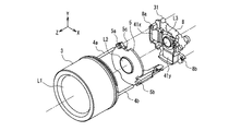
以下、本発明の第1の実施の形態における沈胴式レンズ鏡筒について、図1〜図12を用いて説明する。図1は本実施の形態における沈胴式レンズ鏡筒の分解斜視図、図2(a),(b),(c)は同沈胴式レンズ鏡筒のガイドポールの固定方法を説明する片断面図、図3は同沈胴式レンズ鏡筒のガイドポール支持部を説明する分解斜視図、図4(a),(b),(c)は同沈胴式レンズ鏡筒におけるレンズの傾きを説明する図、図5は同沈胴式レンズ鏡筒におけるカム溝の展開図、図6は同沈胴式レンズ鏡筒におけるカム枠の分解斜視図、図7は同沈胴式レンズ鏡筒における像ぶれ補正装置の構成を示す分解斜視図、図8は像ぶれ補正装置の位置検出部の変位量とマグネットの磁束密度との関係を示す図、図9は同沈胴式レンズ鏡筒の沈胴時での断面図、図10は同沈胴式レンズ鏡筒の望遠端使用時での断面図、図11は同沈胴式レンズ鏡筒の広角端使用時での断面図、図12は同沈胴式レンズ鏡筒における像ぶれ補正装置の動作を説明するブロック図である。
【0022】
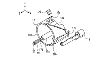
沈胴式のレンズ鏡筒1について、図1から図6を用いて説明する。図示したように、沈胴式レンズ鏡筒の光軸をZ軸(物体側を正とする)とするXYZ3次元直交座標系を設定する。L1は1群レンズ、L2は光軸(Z軸)上を移動して変倍を行う2群レンズ、L3は像ぶれ補正用の3群レンズ、L4は変倍に伴う像面変動の補正及び合焦のために光軸上を移動する4群レンズである。
【0023】
1群保持枠2は1群レンズL1を保持しており、1群レンズL1の中心軸が光軸と平行となるように、筒状の1群移動枠3に対してネジ等で固定されている。この1群移動枠3には、光軸と平行な2本のガイドポール(ガイド部材)4a,4bの一端が固定されている。このガイドポール4の固定方法については、後述する。
【0024】
2群移動枠5は2群レンズL2を保持し、先述の2本のガイドポール4a,4bによって支持されることにより、光軸方向に摺動可能となっている。また2群移動枠5は、ステッピングモータなどの2群レンズ駆動アクチュエータ6の送りネジ6aと、2群移動枠5に設けたラック7のネジ部とが噛合することにより、2群レンズ駆動アクチュエータ6の駆動力にて、光軸方向に移動して変倍を行う。
【0025】
3群枠8は、像ぶれ補正用レンズ群L3(3群レンズ)を保持し、後述する像ぶれ補正装置31を構成している。
【0026】
4群移動枠9は、3群枠8とマスターフランジ10との間に挟まれた、光軸と平行な2本のガイドポール11a,11bにて支持されることにより、光軸方向に摺動可能となっている。また4群移動枠9は、ステッピングモータなどの4群レンズ駆動アクチュエータ12の送りネジ12aと、4群移動枠9に設けたラック13のネジ部とが噛合することにより、4群レンズ駆動アクチュエータ12の駆動力にて、光軸方向に移動し、変倍に伴う像面変動の補正と合焦とを行う。
【0027】
撮像素子(CCD)14は、マスターフランジ10に取り付けられている。
【0028】
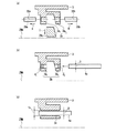
ここで、1群移動枠3へのガイドポール4a,4bの固定方法について、図2(a)〜(c)を用いて説明する。図2(a)〜(c)は、いずれもZ軸に対して一方の側のみを図示した片断面図である。以下の説明では、Z軸に対して一方の側のガイドボール4aの固定部3aへの固定方法を説明するが、他方の側のガイドボール4bの固定部3bへの固定方法も全く同様である。
【0029】
図2(a)は、ガイドポール4aの一端を固定するための固定部3aの樹脂成形方法を示す片断面図である。図2(a)に示すように、1群移動枠3の内側面に、ガイドポール4aの一端を固定するための固定部3aが成形される。固定部3aはZ軸と略平行で、相互に離間した貫通穴3a1,3a2からなる。このような貫通穴3a1,3a2は、3つの成形型29a,29b,29cを用いて樹脂成形される。断面が略台形の成形型29cの両側面に円柱状の成形型29a,29bを当接させた状態で樹脂成形を行う。その後、円柱状の成形型29a,29bをZ軸と略平行で且つ相互に逆向きの方向A,Bに、略台形の成形型29cをZ軸に向かう方向Cに、それぞれ引き抜くことにより、貫通穴3a1,3a2が得られる。このとき、得られる貫通穴3a1,3a2にガイドポール4aを圧入したとき、ガイドポール4aがZ軸と平行に固定されるように、円柱状の成形型29a,29bのZ軸と直交する面内での位置を調整する。
【0030】
その後、図2(b)に示すように、貫通穴3a1,3a2に図の右側(撮像素子14側)からガイドポール4aを圧入する。貫通穴3a1,3a2の内径d1,d2はガイドポール4aの外径Dよりも数ミクロン程度大きく設定されているが、円柱状の成形型29a,29bの中心軸30a,30b(図2(a)参照)のZ軸と直交する面内での相対的位置ずれや傾きにより、ガイドポール4aは2つの貫通穴3a1,3a2によって強固に固定される。かくして、ガイドポール4aはZ軸と平行に1群移動枠3に固定される。
【0031】
図2(c)は、従来のガイドボール4aの固定方法を示した片断面図である。従来の固定方法は以下の通りである。まず、ガイドポール4aの外径Dに対して十分に大きい内径d3の1つの連続する貫通穴からなる固定部3dを樹脂成形する。次いで、ガイドポール4aを固定部3dに挿入し、専用の治具にて仮固定し、ガイドポール4aと固定部3dとの間に接着剤を導入して固定する。
【0032】
以上のように、本実施の形態のガイドボールの固定方法では、ガイドボール4aを貫通穴3a1,3a2に圧入するだけでガイドボール4aをZ軸と平行に固定することができる。従って、従来のようにガイドボール4aを仮固定するための専用の治具や接着剤が不要であり、また、接着剤を固化させる手間や時間も不要である。よって、低コスト且つ短時間にガイドボール4aを固定することができる。さらに、成形型29a,29bのZ軸と直交する面内での位置を調整するだけで、ガイドポール4aをZ軸と平行に精度よく固定することができる。
【0033】
次に、ガイドポール4a,4bの支持方法について、図3を用いて説明する。
【0034】
3群枠8には支持部8a(主軸側),8b(廻り止め側)が設けられている。ガイドポール4a,4bが支持部8a,8bを貫入することにより、ガイドポール4a,4bは光軸と平行に保持される。この2つの支持部8a,8bに対してガイドポール4a,4bが光軸方向に摺動するため、ガイドポール4a,4bの一端に固定された1群移動枠3に保持された1群レンズL1は、3群枠8に設けられた像ぶれ補正用レンズL3に対して精度が保たれる。さらに、ガイドポール4a,4bが、2群移動枠5に設けられた支持部5a(廻り止め側),5b(主軸側)を摺動可能に貫入することにより、2群移動枠5はガイドポール4a,4bに光軸方向に摺動自在に支持されるため、2群移動枠5に保持された2群レンズL2は、3群枠8に設けられた像ぶれ補正用レンズL3に対して精度が保たれる。
【0035】
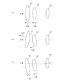
ここで、上記に説明した1群レンズL1,2群レンズL2,3群レンズL3の関係を、図4(a)〜図4(c)を用いて説明する。図中、矢印L1a,L2aは、それぞれ1群レンズL1,2群レンズL2の中心軸の向きを示している。
【0036】
図4(a)は3つのレンズ群L1,L2,L3の理想状態を示しており、Z軸(レンズ鏡筒の光軸であり、これは3群レンズL3の中心軸と一致する)に対して1群レンズL1の中心軸L1a及び2群レンズL2の中心軸L2aが平行になっている。
【0037】
図4(b)は図16に示す従来のレンズ鏡筒と同様の方式により、1群レンズL1及び2群レンズ群L2を、図16の移動レンズ枠62に設けたカムピン62a及び移動レンズ枠63に設けたカムピン63aによりそれぞれ支持した場合を示している。この場合、カムピン62a,63a及びカム溝64,65の精度のばらつきにより、1群レンズL1の中心軸L1a及び2群レンズL2の中心軸L2aは、相互に平行ではなく、且つZ軸とも平行とはならない。従って、光学性能が悪化する可能性が大きい。
【0038】
図4(c)は本実施の形態の場合を示している。1群レンズL1及び2群レンズL2は、同一のガイドポール4a,4bに支持されているため、1群レンズL1の中心軸L1a及び2群レンズL2の中心軸L2aがZ軸に対して仮に傾いたとしても、両中心軸L1a,L2aの向きは常に一致する。すなわち、光学性能に対する影響度が最も高い像ぶれ補正用レンズ群L3に対して1群レンズL1及び2群レンズL2は常に同一方向に傾くため、光学性能の悪化量を最小限に抑えることができる。
【0039】
次に、1群レンズL1を光軸方向に移動させる構成について説明する。
【0040】
略中空円筒状の駆動枠15の撮像素子14側の内周面の一部にギア15aが形成されている。また、その物体側(Z軸の正の側)の内周面に略120°間隔に3つの突起部15bが形成されている。突起部15bが1群移動枠3の撮像素子14側の外周面に設けられた周方向の3つの溝部3aと係合することにより、駆動枠15は1群移動枠3に対して光軸を中心として相対的に回転可能であり、光軸方向には駆動枠15と1群移動枠3とは一体で移動する。さらに駆動枠15の内周面には、3本のカムピン16a,16b,16cが120°間隔に圧入固定されている。
【0041】
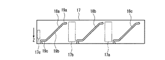
筒状のカム枠17の外表面には、略120゜間隔にて3本のカム溝18a,18b,18cが形成されている。図5に、カム枠17の外周面の展開図を示す。カム枠17のカム溝18a,18b,18cに駆動枠15のカムピン16a,16b,16cがそれぞれ係合する。各カム溝18a,18b,18cは、撮像素子14側(Z軸の負の側)にカム枠17の周方向とほぼ平行な部分19aと、物体側(Z軸の正の側)にカム枠17の周方向とほぼ平行な部分19cと、部分19aと部分19cとを螺旋状に繋ぐ部分19bとを有する。カムピン16a,16b,16cが、部分19aにあるとき、1群レンズL1は撮像素子14側に繰り込まれた状態(沈胴状態)で停止する。この状態から、駆動枠15が光軸回りに回転することにより、カムピン16a,16b,16cは部分19bを経て、部分19cに至る。カムピン16a,16b,16cが部分19cにあるとき、1群レンズL1は物体側に繰り出されて停止する。
【0042】
図6に示すように、カム枠17の外周面であって、カム溝18bとカム溝18cとの間には、スプライン状の駆動ギア19の両端の駆動ギア軸20を回転可能に保持する軸受け部17dと、駆動ギア19との干渉を避けるために半円筒面状に窪ませた駆動ギア取り付け部(凹部)17aとが形成されており、これにより駆動ギア19はカム枠17の外周面上に回転自在に保持されている。駆動ギア19は、後述するマスターフランジ10に取り付けられた駆動ユニット21の駆動力を駆動枠15に設けられたギア部15aに伝達する。したがって、駆動ギア19が回転することにより、駆動枠15が光軸の回りに回転し、この際、駆動枠15に設けられたカムピン16a,16b,16cが、カム枠17のカム溝18a,18b,18c内を移動することにより、駆動枠15は光軸方向にも移動する。このとき、1群移動枠3は、これに固定された2本のガイドポール4a,4bが3群枠8の支持部8a,8bに貫入されていることにより、光軸回りの回転が制限されるから、駆動枠15が光軸方向に移動するに従って、1群移動枠3は光軸方向に直進移動する。
【0043】
2群移動枠5の駆動アクチュエータ6は、カム枠17の取り付け部17bに固定される。また、4群移動枠9の駆動アクチュエータ12は、マスターフランジ10の取り付け部10aに固定される。駆動ギア19に駆動力を伝達する駆動ユニット21は、駆動アクチュエータ22と複数のギアからなる減速ギアユニット23とからなり、マスターフランジ10の取り付け部10bに固定される。
【0044】
2群移動枠5用の原点検出センサ25は、発光素子および受光素子からなる光検出センサであり、2群移動枠5の光軸方向の位置、つまり2群レンズL2の原点位置を検出する。4群移動枠9用の原点検出センサ26は、4群移動枠9の光軸方向の位置、つまり4群レンズL4の原点位置を検出する。駆動枠15用の原点検出センサ27は、駆動枠15の回転方向の位置、つまり駆動枠15と一体で移動する1群移動枠3及び1群レンズL1の原点位置を検出する。
【0045】
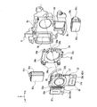
次に、像ぶれ補正用レンズ群L3を用いて像ぶれ補正を行う像ぶれ補正装置31について、図7を用いて説明する。
【0046】
撮影時に像ぶれを補正するための像ぶれ補正用レンズ群L3は、第1の方向(Y方向)であるピッチング方向と、第2の方向(X方向)であるヨーイング方向とに移動可能であるピッチング移動枠32に固定されている。このピッチング移動枠32は、−X方向側に軸受32aと+X方向側に廻り止め32bとを有している。この軸受32aにY軸方向と平行なピッチングシャフト33aを挿入し、廻り止め32bに後述するY軸方向と平行なピッチングシャフト33bを係合することにより、ピッチング移動枠32は第1の方向(Y)方向に摺動可能になっている。
【0047】
ピッチング移動枠32に対して−Z方向側には、像ぶれ補正用レンズ群L3を第2の方向(X方向)に移動させるヨーイング移動枠34が取り付けられている。ヨーイング移動枠34には、先ほど述べたピッチング移動枠32をピッチング方向(Y方向)に摺動させるための2本のピッチングシャフト33a,33bの両端を固定する固定部34aが設けられている。また、ヨーイング移動枠34は、+Y方向側に軸受34bと−Y方向側にヨーイングシャフト35b及びその両端が圧入固定される固定部34cとを有している。この軸受34bにX方向と平行なヨーイングシャフト35aを挿入し、X方向と平行なヨーイングシャフト35bを3群枠8の廻り止め部8dに係合することにより、ヨーイング移動枠34は第2の方向(X方向)に摺動可能になっている。
【0048】
ヨーイング移動枠34に対して−Z方向側に設けられた3群枠8には、先述したヨーイング移動枠34をヨーイング方向(X方向)に摺動させるためのヨーイングシャフト35aの両端を固定する固定部8cとヨーイングシャフト35bを係合する廻り止め部8dとが設けられている。
【0049】
略L字型形状の電気基板36は、ピッチング移動枠32の−Z方向側の面に取り付けられている。電気基板36には、像ぶれ補正用レンズ群L3をピッチング方向に駆動する第1のコイル37y及びヨーイング方向に駆動する第2のコイル37xと、像ぶれ補正用レンズ群L3のピッチング方向の位置を検出するホール素子38y及びヨーイング方向の位置を検出するホール素子38xとが設けられている。なお、このコイル37y,37xは、積層コイルとして電気基板36に一体に構成されている。
【0050】
マグネット39y、39xは片側に2極着磁されている。このマグネット39y,39xは、それぞれ断面コの字型のヨーク40y、40xに固定されている。ヨーク40yは、Y方向より、3群枠8の嵌合部8yに圧入固定される。同様に、ヨーク40xは、X方向より、3群枠8の嵌合部8xに圧入固定される。
【0051】
第1の電磁アクチュエータ41yは、第1のコイル37yと、マグネット39yと、第1のヨーク40yとにより構成される。同様に、第2の電磁アクチュエータ41xは、第1のコイル37xと、マグネット39xと、第1のヨーク40xとにより構成される。第1の電磁アクチュエータ41yがピッチング移動枠32を第1の方向であるピッチング方向(Y方向)に駆動する第1の駆動手段を構成し、第2の電磁アクチュエータ41xがピッチング移動枠32を第2の方向であるヨーイング方向(X方向)に駆動する第2の駆動手段を構成する。
【0052】
以上の構成によって、電気基板36の第1のコイル37yに電流が流されると、第1のマグネット39yとヨーク40yとにより第1の方向であるピッチング方向(Y方向)に沿った電磁力が発生する。これと同様に、電気基板36の第2のコイル37xに電流が流されると、第2のマグネット38xとヨーク40xとにより第2の方向であるヨーイング方向(X方向)に沿った電磁力が発生する。このように2つの電磁アクチュエータ41y,41xにより、像ぶれ補正用レンズ群L3は光軸Zにほぼ垂直なX,Yの2方向に駆動される。
【0053】
次に、像ぶれ補正用レンズ群L3の位置を検出する位置検出部42y,42xについて説する。磁束を電気信号に変換するホール素子38y,38xは、電気基板36に位置決め固定されている。検出用マグネットとしては、先に説明した電磁アクチュエータ41y,41xのマグネット39y,39xが兼用される。したがって、ホール素子38y、38xとマグネット39y,39xとにより位置検出部42y,42xが構成される。ここで、図8を用いてマグネット39x,39yの磁束の状態を説明する。図の横軸は光軸を中心としてピッチング方向(Y方向)又はヨーイング方向(X方向)の位置を、縦軸は磁束密度をそれぞれ示している。また横軸の中央は、マグネット39x,39yの2極着磁の境界部分であり、このとき磁束密度はゼロとなる。この位置は、像ぶれ補正用レンズ群L3の光軸中心と略一致する。マグネット39y,39xに対して、ホール素子38y,38xが移動することにより、変位量がゼロの位置を中心とする破線で示す範囲内では、変位量の変化に対して磁束密度が略直線的に変化する。したがって、ホール素子38y,38xから出力される電気信号を検出することにより、像ぶれ補正用レンズ群L3のピッチング方向(Y方向)およびヨーイング方向(X方向)の位置を検出することが可能となる。
【0054】
フレキシブルプリントケーブル43は、電気基板36に取り付けられコイル37x,37y、ホール素子38x,38yと図示せぬカメラ本体の回路との間の信号の伝達を行う。
【0055】
以上の構成要素32〜43により、像ぶれ補正装置31を構成している。
【0056】
このように構成された沈胴式レンズ鏡筒1について、その動作を以下に述べる。
【0057】
最初に、この沈胴式のレンズ鏡筒1の動作について、まず図9に示す非撮影時(未使用時)の状態から、図10に示す状態を経て、図11に示す撮影時(広角端)の状態に移行する際の動作について説明する。
【0058】
図9の非撮影時の状態より、カメラ本体の電源スイッチ等がオンとなると撮影準備状態になる。最初に1群レンズL1を駆動する1群レンズ駆動アクチュエータ22が回転し、減速ギアユニット23を介して駆動ギア19を回転させる。駆動ギア19が回転することにより、駆動ギア19と噛合している駆動枠15が、カム溝18a,18b,18cに沿って光軸を中心として回転する。そして原点検出センサ27を初期化した後、駆動枠15が物体方向(Z軸方向)に移動することにより、1群移動枠3も物体方向に移動する。そして、1群レンズ駆動アクチュエータ22が所定の回転量だけ回転したのを図示せぬ回転量検出センサが検出すると、1群移動枠3が所定の位置まで移動した後、1群レンズ駆動駆動アクチュエータ22の回転が停止する。この停止位置では、図5のカム溝の展開図において、カムピン16a,16b,16cは、カム枠17の周方向とほぼ平行な部分19cに到達している。図10はこのときの状態を示している。
【0059】
次に、2群レンズ駆動アクチュエータ6が回転し、送りネジ6aを介してラック7を駆動することにより、2群移動枠5がZ軸に沿って動き出す。そして原点検出センサ25を初期化した後、物体方向に移動し、2群移動枠5は、図11に示す広角端の位置にて停止し、カメラ本体は撮影可能状態となる。ここで1群移動枠3および2群移動枠5は、3群枠8の支持部8a,8bに保持された同一のガイドポール4a,4bにて支えられながら所定位置まで移動する。したがって、1群レンズL1および2群レンズL2が光軸に対して傾いたとしても、それらの傾き方向は像ぶれ補正用レンズ群L3に対して同一であるため、所定の光学性能を確保することができる。
【0060】
実際の撮影時には、2群レンズ駆動アクチュエータ6と4群レンズ駆動アクチュエータ12により、それぞれ変倍動作と変倍に伴う像面変動の補正及び合焦の動作とを行う。変倍を行う際、広角端の状態では、図11に示す状態にて撮影を行い、望遠端の状態では、2群レンズL2を−Z方向(撮像素子14側端)に移動させて図10に示す状態にて撮影を行う。よって、広角端から望遠端まで、任意の位置にて撮影することが可能となる。
【0061】
次に図11に示す撮影時の状態から、図10に示す状態を経て、図9に示す非撮影時の状態に移行する際の動作について説明する。
【0062】
図11の撮影時の状態(広角端)より、カメラの電源スイッチ等がオフされると撮影が終了し、最初に2群移動枠5が2群レンズ駆動アクチュエータ6により撮像素子14側に移動して、図10に示す状態となる。次に1群レンズ駆動アクチュエータ22が回転し、減速ギアユニット23を介して駆動ギア19を上記とは逆方向に回転させる。駆動ギア19が回転することにより、駆動ギア19と噛合している駆動枠15が光軸を中心として回転し、同時に、カム溝18a,18b,18cによって撮像素子14方向に移動することにより、1群移動枠3も移動する。そして原点検出センサ27により駆動枠15の回転を検出すると、1群移動枠3が所定の位置まで移動した後、1群レンズ駆動アクチュエータ22の回転が停止する。この停止位置では、図5のカム溝の展開図において、カムピン16a,16b,16cは、カム枠17の周方向とほぼ平行な部分19aに到達している。これにより、図9に示す状態に移行し、撮影時の状態に比べて長さCだけ短くなった沈胴状態となる。
【0063】
ここで、沈胴式レンズ鏡筒1の光軸方向の長さを変える沈胴動作については1群レンズL1を駆動する1群レンズ駆動アクチュエータ22を用い、ズーミング動作については2群レンズ駆動アクチュエータ6を単独で使用している。そのため、実際の撮影でのズーミング動作は、1群レンズL1を繰り出した状態で行うため、1群レンズ駆動アクチュエータ22を動作させる必要はなく、2群レンズ駆動アクチュエータ6のみを駆動して図10と図11との間の所定位置に2群レンズL2を移動させてズーミングを行うことができる。したがって、ズーミング動作を行うなどの撮影を行う際には、図16に示した従来方式の沈胴式レンズ鏡筒とは異なり、ズーム倍率に応じて、鏡筒の繰り出し動作及び繰り込み動作を行う必要がない。図16の従来の沈胴式のレンズ鏡筒においては、ズーミング動作時に、1つの駆動アクチュエータ69を回転させ、減速ギアトレイン68を介してカム筒61を回転させて、移動レンズ枠62,63を同時に駆動していたため、ズーミング速度が遅く、駆動音が大きい。本発明の沈胴式のレンズ鏡筒1は、2群レンズ駆動アクチュエータ6としてステッピングモータを使用し、そのステッピングモータに取り付けられた送りネジ6aを介して、2群移動枠5を直接駆動するため、送り速度も速く、動作音も小さい。従って、沈胴式のレンズ鏡筒であっても、ズーム速度の高速化、ズーム音の低騒音化を実現できる。したがって、撮影者は瞬時に画角を変更することが可能となり、被写体を追いかける、動画を撮影するなど、従来のDSCでは不向きであった使用方法を行うことができる。
【0064】
次に、像ぶれ補正装置31の動作について、図12を用いて説明する。
【0065】
像ぶれは、手ぶれによりカメラに変位や振動が生じることに発生する。像ぶれ補正装置31を内蔵したカメラでは、この変位や振動を、検出方向が略90゜になるように配置された2個の角速度センサ44y,44xにより検出する。角速度センサ44y,44xからの出力は時間積分される。そしてカメラ本体のぶれ角度に変換され、像ぶれ補正用レンズ群L3の目標位置情報に変換される。この目標位置情報に応じて像ぶれ補正用レンズ群L3を移動させるために、サーボ駆動回路45は、目標位置情報と位置検出部42y,42xにより検出された現在の像ぶれ補正用レンズ群L3の位置情報との差を演算し、電磁アクチュエータ41y,41xに信号を伝送する。電磁アクチュエータ41y,41xは、この信号に基づいて像ぶれ補正用レンズ群L3を駆動する。
【0066】
第1の方向であるピッチング方向(Y方向)の駆動については、サーボ駆動回路45から指令を受けた電磁アクチュエータ41yは、フレキシブルプリントケーブル43を通じて第1のコイル37yに電流を流し、ピッチング方向(Y方向)に力を発生させ、ピッチング移動枠32をピッチング方向(Y方向)に駆動する。
【0067】
また、第2の方向であるヨーイング方向(X方向)の駆動については、サーボ駆動回路45から指令を受けた電磁アクチュエータ41xは、フレキシブルプリントケーブル43を通じて第2のコイル37xに電流を流し、ヨーイング方向(X方向)に力を発生させ、ヨーイング移動枠34とこの上に搭載されたピッチング移動枠32とをヨーイング方向(X方向)に駆動する。
【0068】
よって、像ぶれ補正用レンズ群L3をピッチング移動枠32及びヨーイング移動枠34により、光軸と直交する2次元平面内において任意に動かすことが可能となるため、手ぶれにより発生する像ぶれを補正することが可能となる。
【0069】
以上のように本実施の形態によれば、1群レンズL1及び2群レンズL2が、像ぶれ補正用レンズL3に対し、少なくとも同一方向に傾くように構成したことにより、像ぶれ補正装置が搭載されたレンズ鏡筒において、光学性能の低下量を最小限に抑えつつ、未使用時の全長を短くすることが可能となる。
【0070】
また、ガイドボール4a,4bが、光軸方向に貫通する、相互に離間した二つの貫通穴に圧入されて固定されていることにより、従来の、ガイドポールを専用の治具で仮固定して接着する方式に比べ、組立工数の削減を図ることができる。また、貫通穴を形成する成形型29a,29bのZ軸と直交する面内での相対位置を調整することにより、ガイドボール4a,4bの向きを容易に調整することができ、ガイドポール4a,4bを光軸と平行に固定することができる。
【0071】
なお、本実施の形態においては、1群レンズL1を設けた1群枠2と1群移動枠3とを別々の構成としたが、一体の構成とし、その一体部分にガイドポールを固定する構成としても良い。
【0072】
また、本実施の形態に記載した像ぶれ補正装置31において、ホール素子を用いた位置検出手段を別の場所に設けた構成であっても良い。あるいは磁気式の位置検出手段に替えて、例えば発光素子と受光素子とからなる光学式の位置検出手段を設けても差し支えない。
【0073】
また、本実施の形態においては、1群移動枠3と2群移動枠5とを順に移動させたが、繰り出し又は沈胴時間の短縮のために両者を同時に移動させてもよい。例えば、鏡筒の繰り出し時には、1群移動枠3の移動が開始し、1群移動枠3が所定位置に停止する前に、2群移動枠5の沈胴位置からの移動を開始し、広角端位置に停止させてもよい。また、鏡筒の沈胴時には、2群移動枠5の移動が開始し、2群移動枠5が所定位置に停止する前に、1群移動枠3の移動を開始させ、沈胴位置に停止させてもよい。
【0074】
(実施の形態2)
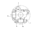
次に、本発明の第2の実施の形態における沈胴式レンズ鏡筒について、図13、図14を用いて説明する。図13は本実施の形態の沈胴式レンズ鏡筒における駆動ギア19と像ぶれ補正装置31との位置関係を説明する分解斜視図、図14は、本実施の形態の沈胴式レンズ鏡筒における駆動ギア19と像ぶれ補正装置31とを光軸と平行な方向から見た正面図である。本実施の形態のレンズ鏡筒は、以下の説明を除いて実施の形態1と同様である。実施の形態1と同一の構成要素については同一の符号を付し、その説明を省略する。
【0075】
図13を用いて、駆動ギア19の取り付け位置について説明する。
【0076】
駆動ギア19は、マスターフランジ10に取り付けられた減速ギアユニット21の駆動力を駆動枠15に伝達するためのものであり、駆動枠15が光軸方向に移動するため、光軸方向に所定の長さが必要となる。また、駆動枠15を光軸方向に移動させるためにカム枠17にカム溝18a,18b,18cを設けており、駆動ギア19をこのカム溝と干渉しないようにカム枠17に取り付ける必要がある。更に、マスターフランジ10とカム枠17との間には、像ぶれ補正装置31が設けられる。このような制約のために、駆動ギア19は、像ぶれ補正装置31と干渉することがないように、光軸に対して90°をなすような位置に配置された2つの電磁アクチュエータ41y,41xの間に配置される。この結果、カム枠17に駆動ギア19を設け、さらにはその両側にカム溝18b,18cを形成できるので、像ぶれ補正装置31を有した沈胴式レンズ鏡筒1において、像ぶれ補正装置31と沈胴用の駆動ギア19とが干渉することなく、駆動ギア19を光軸中心方向に寄せて配置することが可能となる。
【0077】
さらに図14で示すように、駆動ギア19を2つの電磁アクチュエータ41y,41xの間に配置することにより、2点鎖線で示したカム枠17の円内に像ぶれ補正装置31を搭載した3群枠8がほぼ収まるので、沈胴式レンズ鏡筒1の小径化が可能となる。
【0078】
以上のように本実施の形態によれば、2つの像ぶれ補正用アクチュエータ41y,41xの間に沈胴用の駆動ギア19を設けたことにより、カム溝と干渉することなく、駆動ギア19を光軸中心方向に寄せることが可能となるため、レンズ鏡筒の全長の短縮と共に、小径化を図ることができる。
【0079】
(実施の形態3)
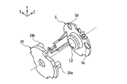
次に、本発明の第3の実施の形態における沈胴式レンズ鏡筒について、図15を用いて説明する。図15は本実施の形態の沈胴式レンズ鏡筒におけるシャッターユニット24と2群移動枠5との位置関係を説明する分解斜視図である。本実施の形態のレンズ鏡筒は、以下の説明を除いて実施の形態1と同様である。実施の形態1と同一の構成要素については同一の符号を付し、その説明を省略する。
【0080】
図15を用いて、シャッターユニット24の駆動アクチュエータ24a,24bの配置位置について説明する。
【0081】
シャッターユニット24は、撮像素子14の露光量及び露光時間を制御するため、一定の開口径を形成する絞り羽根とシャッター羽根とを備える。絞り羽根は駆動アクチュエータ24aにより駆動され、シャッター羽根は駆動アクチュエータ24bにより駆動される。駆動アクチュエータ24a,24bは、シャッターユニット24の、像ぶれ補正装置31とは反対側の面、すなわち2群移動枠5側の面に突出して設けられている。そこで、2群移動枠5のシャッターユニット24側の面には、駆動アクチュエータ24a,24bの位置に対応する2箇所に凹部5c,5dが設けられている。この結果、2群移動枠5とシャッターユニット24との距離が狭くなった時に、駆動アクチュエータ24a,24bの一部が2群移動枠5の凹部5c,5dにそれぞれ入り込むことにより、駆動アクチュエータ24a,24bと2群移動枠5との干渉が防止される。
【0082】
よって、例えば図10に示す望遠端においては、2群レンズL2と像ぶれ補正レンズ群L3との間隔を所定の間隔とするため、シャッターユニット24の駆動アクチュエータ24aの一部が、2群移動枠5の凹部5cに入り込む。
【0083】
以上のように本実施の形態によれば、シャッターユニット24の駆動アクチュエータ24a,24bを、シャッターユニット24の2群移動枠5側の面に設け、且つ、2群移動枠5に駆動アクチュエータ24a,24bの一部が入り込む凹部を設けることにより、シャッターユニット24と2群移動枠5との間隔を小さくすることができるので、沈胴式レンズ鏡筒の全長を短くすることができる。
【0084】
【発明の効果】
以上のように、本発明の沈胴式レンズ鏡筒によれば、第1レンズ群、第2レンズ群が、像ぶれ補正用の第3レンズ群に対し、少なくとも同一方向に傾く。このように、光学性能への影響度が最も高い、像ぶれ補正用の第3レンズ群に対する第1,第2レンズ群の傾き方向を同一方向にすることができるので、光学性能の低下量を最小限に抑えつつ、全長が短い、像ぶれ補正装置が搭載された沈胴式レンズ鏡筒を提供することができる。
【0085】
また、ズーミング用駆動アクチュエータとは別に沈胴用アクチュエータとして第1枠を光軸方向に移動させる駆動手段を備え、撮影時には第1枠を物体側に移動させた状態とし、非撮影時には第1枠を像面側に移動させた状態とするので、ズーミング時にはカム枠が駆動されず、ズーム時間の高速化、ズーム音の低騒音化が実現できる。
【図面の簡単な説明】
【図1】本発明の実施の形態1における沈胴式レンズ鏡筒の分解斜視図である。
【図2】図2(a)は、本発明の実施の形態1における沈胴式レンズ鏡筒において、ガイドポールを固定するために1群移動枠に固定部を成形する方法を示す片断面図である。図2(b)は、本発明の実施の形態1における沈胴式レンズ鏡筒において、1群移動枠に形成された固定部にガイドポールを圧入固定する様子を示した片断面図である。図2(c)は、従来のガイドボールの固定方法を示した片断面図である。
【図3】本発明の実施の形態1における沈胴式レンズ鏡筒のガイドポール支持部を説明する分解斜視図である。
【図4】図4(a)は理想的な沈胴式レンズ鏡筒におけるレンズの傾きを示した図、図4(b)は従来の沈胴式レンズ鏡筒におけるレンズの傾きを示した図、図4(c)は本発明の実施の形態1における沈胴式レンズ鏡筒におけるレンズの傾きを示した図である。
【図5】本発明の実施の形態1における沈胴式レンズ鏡筒におけるカム溝の展開図である。
【図6】本発明の実施の形態1における沈胴式レンズ鏡筒におけるカム枠の分解斜視図である。
【図7】本発明の実施の形態1における沈胴式レンズ鏡筒における像ぶれ補正装置の構成を示す分解斜視図である。
【図8】本発明の実施の形態1における沈胴式レンズ鏡筒における像ぶれ補正装置の位置検出部の変位量と磁束密度との関係を示す図である。
【図9】本発明の実施の形態1における沈胴式レンズ鏡筒の沈胴時での断面図である。
【図10】本発明の実施の形態1における沈胴式レンズ鏡筒の望遠端使用時での断面図である。
【図11】本発明の実施の形態1における沈胴式レンズ鏡筒の広角端使用時での断面図である。
【図12】本発明の実施の形態1における沈胴式レンズ鏡筒における像ぶれ補正装置の動作を説明するためのブロック図である。
【図13】本発明の実施の形態2における沈胴式レンズ鏡筒における駆動ギアと像ぶれ補正装置との位置関係を説明する分解斜視図である。
【図14】本発明の実施の形態2における沈胴式レンズ鏡筒における駆動ギアと像ぶれ補正装置とを光軸と平行な方向から見た正面図である。
【図15】本発明の実施の形態3における沈胴式レンズ鏡筒のシャッターユニットと2群移動枠との位置関係を説明する分解斜視図である。
【図16】従来の沈胴式レンズ鏡筒の分解斜視図である。
【符号の説明】
L1 1群レンズ
L2 2群レンズ(ズーム用レンズ)
L3 像ぶれ補正用レンズ群(3群レンズ)
L4 4群レンズ(フォーカス用レンズ)
1 沈胴式レンズ鏡筒
2 1群枠
3 1群移動枠
4a,4b ガイドポール
5 2群移動枠
5c,5d 2群移動枠凹部
6 2群レンズL2駆動アクチュエータ
8 3群枠
8a,8b ガイドポール支持部
9 4群移動枠
10 マスターフランジ
12 4群レンズL4駆動アクチュエータ
14 撮像素子(CCD)
15 駆動枠
16a,16b,16c カムピン
17 カム枠
17a 駆動ギア取り付け部
17b 駆動アクチュエータの取り付け部
17c 原点検出センサの取り付け部
17d 駆動ギアの軸受け部
18a,18b,18c カム溝
19 駆動ギア
21 駆動ギアユニット
22 1群レンズL1駆動アクチュエータ
24 シャッターユニット
24a 駆動アクチュエータ
25 2群レンズ用原点検出センサ
31 像ぶれ補正装置
32 ピッチング移動枠
34 ヨーイング移動枠
36 電気基板
37y,37x コイル
38y,38x ホール素子
39y,39x マグネット
40y,40x ヨーク
41y,41x 電磁アクチュエータ
42y、42x 位置検出部
43 フレキシブルプリントケーブル
44x,44y 角速度センサ
45 サーボ駆動回路[0001]
TECHNICAL FIELD OF THE INVENTION
The present invention relates to a collapsible lens barrel equipped with an image blur correction device. In particular, the present invention relates to a collapsible lens barrel having a reduced size and a reduced overall length while maintaining optical performance.
[0002]
[Prior art]
2. Description of the Related Art In recent years, digital still cameras (hereinafter, referred to as DSCs) that can immediately confirm a captured image have been rapidly spread. As a lens barrel for this DSC, a so-called collapsible lens barrel in which the length of the lens barrel is shortened during non-photographing is generally adopted in consideration of portability during non-photographing. .
[0003]
FIG. 16 shows an exploded perspective view of a conventional collapsible lens barrel (for example, see Patent Document 1). The collapsible lens barrel 60 is an optical system that changes the focal length by moving the movable lens frames 62 and 63 in the front-rear direction by one cam cylinder 61. Cam grooves 64, 65 are formed on the inner peripheral surface of the cam cylinder 61, and the cam grooves 64, 65 determine the movement trajectories of the movable lens frames 62, 63, respectively. The movable lens frames 62 and 63 move in the optical axis (Z-axis) direction when three cam pins 62a and 63a provided on the respective outer peripheral surfaces engage with the cam grooves 64 and 65, respectively. The cam cylinder 61 is provided outside the fixed cylinder 70 and is rotatable around the optical axis. A gear 66 is formed on the outer periphery of the cam cylinder 61, and a driving force transmission gear 67 meshes with the gear 66. The driving force transmission gear 67 is connected to an output shaft of a cam cylinder driving actuator 69 via a reduction gear train 68. Therefore, when the cam cylinder driving actuator 69 is driven, the driving force is transmitted to the driving force transmission gear 67 via the reduction gear train 68, and the cam cylinder 61 is rotated. As a result, the movable lens frames 62 and 63 move along the shapes of the cam grooves 64 and 65, respectively, so that zooming is performed from the collapsed state via the wide-angle end.
[0004]
Also, with the increase in the magnification of the optical zoom, the influence of camera shake has become conspicuous, and in order to reduce the influence, a DSC incorporating an image blur correction device is also being commercialized. As the image blur correction device for DSC, a method has been proposed in which a camera lens is corrected by moving a correction lens group in two directions perpendicular to the optical axis to obtain a stable image (for example, Patent Document 2).
[0005]
[Patent Document 1]
JP-A-2002-107598
[0006]
[Patent Document 2]
JP 2001-117129 A
[0007]
[Problems to be solved by the invention]
However, the above-mentioned conventional collapsible lens barrel has the following problems.
[0008]
1. Due to the miniaturization of the DSC main body, a retractable lens barrel for shortening the entire length of the lens barrel when not in use is generally used as a lens barrel for the DSC. However, a lens barrel in which a retractable lens is mounted on an image blur correction device has not been developed.
[0009]
2. In a four-unit lens barrel with a high-magnification function equipped with an image blur correction device, a large number of lenses and strict assembly precision are required to improve the optical performance. In the conventional collapsible lens mirror shown in FIG. 16, when the lens is moved in the optical axis direction in order to collapse the lens barrel, the optical performance is significantly deteriorated, so that it is difficult to apply to a high-magnification zoom lens. .
[0010]
3. In the above-mentioned conventional collapsible lens barrel, since zooming is performed using the reduction gear train 68 and the cam frame (cam cylinder 61), it is not suitable for increasing the zoom speed and reducing the noise of the zoom sound. It is.
[0011]
Accordingly, the present invention is directed to a high-magnification compatible lens barrel equipped with an image blur correction device, which is capable of realizing miniaturization by a retractable type and minimizing the amount of deterioration in optical performance due to the retractable type. The purpose is to provide a tube.
[0012]
[Means for Solving the Problems]
In order to achieve the above object, a collapsible lens barrel according to the present invention includes a first frame for holding a first lens group, and at least two bar-like members having one end fixed to the first frame and parallel to each other. A second frame, which is disposed closer to the image plane than the first frame, holds the second lens group, and is slidably held by the guide member, and an image plane higher than the second frame. Image blur correction means, which is disposed on the side, supports the guide member substantially slidably in parallel with the optical axis, and holds a third lens group for image blur correction; and Driving means for moving the first frame toward the object side during photographing, and moving the first frame toward the image plane during non-photographing. Features.
[0013]
According to the retractable lens barrel of the present invention described above, the first lens group and the second lens group are inclined at least in the same direction with respect to the third lens group for image blur correction. As described above, the inclination directions of the first and second lens groups with respect to the third lens group for correcting image blur, which have the highest degree of influence on the optical performance, can be made the same direction. It is possible to provide a collapsible lens barrel equipped with an image blur correction device having a short overall length while minimizing the length.
[0014]
Also, a driving means for moving the first frame in the optical axis direction is provided as a collapsing actuator separately from the zooming driving actuator, and the first frame is moved to the object side during photographing, and the first frame is moved when not photographing. Since the cam frame is moved to the image plane side, the cam frame is not driven during zooming, so that the zoom time can be increased and the zoom sound can be reduced.
[0015]
In the above retractable lens barrel of the present invention, the guide member may be fixed to the first frame by being press-fitted into two mutually separated through holes penetrating in the optical axis direction. preferable.
[0016]
According to such a preferred configuration, the parallelism of the guide member to the optical axis can be easily adjusted, and the optical axis and the guide member can be fixed in parallel. Also, the number of assembly steps can be reduced as compared with the conventional method in which the guide means is temporarily fixed and bonded by a dedicated jig.
[0017]
In the collapsible lens barrel of the present invention, a cam frame having a plurality of cam grooves and a portion of the cam frame where the cam grooves are not formed are provided with the optical axis direction as a longitudinal direction. A driving frame that engages with a cam groove of the cam frame, and engages with the driving gear to rotate about the optical axis to move the first frame in the optical axis direction; It is preferable that the apparatus further includes first and second actuators for driving the three lens groups in two directions orthogonal to the optical axis, and the drive gear is disposed between the first and second actuators.
[0018]
According to this preferred configuration, the drive gear is provided between the first and second actuators for correcting image blur, so that the drive gear can be moved to the center of the optical axis without interfering with the cam groove. Therefore, the diameter of the lens barrel can be reduced.
[0019]
Further, in the collapsible lens barrel according to the present invention, a shutter unit is further provided between the image blur correcting unit and the second frame, and the shutter unit is provided with a drive actuator on a surface on the second frame side. Preferably, the second frame includes a concave portion into which a part of the drive actuator enters.
[0020]
According to this preferred configuration, the distance between the shutter unit and the second group moving frame can be reduced, so that the total length of the retractable lens barrel can be reduced.
[0021]
BEST MODE FOR CARRYING OUT THE INVENTION
The collapsible lens barrel according to the first embodiment of the present invention will be described below with reference to FIGS. FIG. 1 is an exploded perspective view of a retractable lens barrel according to the present embodiment, and FIGS. 2A, 2B, and 2C are partial cross-sectional views illustrating a method of fixing a guide pole of the retractable lens barrel. FIG. 3 is an exploded perspective view illustrating a guide pole supporting portion of the collapsible lens barrel, and FIGS. 4A, 4B, and 4C are diagrams illustrating tilt of the lens in the collapsible lens barrel. 5 is a development view of a cam groove in the collapsible lens barrel, FIG. 6 is an exploded perspective view of a cam frame in the collapsible lens barrel, and FIG. 7 is a configuration of an image blur correction device in the collapsible lens barrel. FIG. 8 is a diagram showing the relationship between the amount of displacement of the position detection unit of the image blur correction device and the magnetic flux density of the magnet. FIG. 9 is a sectional view of the collapsible lens barrel when collapsed. 10 is a sectional view of the collapsible lens barrel when the telephoto end is used, and FIG. 11 is a sectional view of the collapsible lens barrel. Kakutan sectional view at the time of use, FIG. 12 is a block diagram illustrating the operation of the image blur correction apparatus in the collapsible lens barrel.
[0022]
The collapsible lens barrel 1 will be described with reference to FIGS. As shown in the drawing, an XYZ three-dimensional orthogonal coordinate system is set in which the optical axis of the retractable lens barrel is the Z axis (the object side is positive). L1 is a first-group lens, L2 is a second-group lens that moves on the optical axis (Z-axis) to perform zooming, L3 is a third-group lens for image blur correction, and L4 is a lens for correcting image plane fluctuation due to zooming. The fourth lens group moves on the optical axis for focusing.
[0023]
The first-group holding frame 2 holds the first-group lens L1, and is fixed to the cylindrical first-group moving frame 3 with screws or the like so that the central axis of the first-group lens L1 is parallel to the optical axis. I have. One end of two guide poles (guide members) 4a, 4b parallel to the optical axis is fixed to the first group moving frame 3. The method of fixing the guide pole 4 will be described later.
[0024]
The second
[0025]
The
[0026]
The fourth
[0027]
The image pickup device (CCD) 14 is attached to the
[0028]
Here, a method of fixing the
[0029]
FIG. 2A is a partial cross-sectional view showing a resin molding method of the fixing
[0030]
Thereafter, as shown in FIG. 2B, the
[0031]
FIG. 2C is a sectional view showing a conventional method of fixing the
[0032]
As described above, according to the guide ball fixing method of the present embodiment, the
[0033]
Next, a method of supporting the
[0034]
The
[0035]
Here, the relationship between the first group lens L1, the second group lens L2, and the third group lens L3 described above will be described with reference to FIGS. 4 (a) to 4 (c). In the figure, arrows L1a and L2a indicate the directions of the central axes of the first group lens L1 and the second group lens L2, respectively.
[0036]
FIG. 4A shows an ideal state of the three lens units L1, L2, and L3, with respect to the Z axis (the optical axis of the lens barrel, which coincides with the central axis of the third lens unit L3). The center axis L1a of the first lens unit L1 and the center axis L2a of the second lens unit L2 are parallel to each other.
[0037]
FIG. 4B shows a cam pin 62a and a movable lens frame 63 provided on the movable lens frame 62 of FIG. 16 by using the same method as the conventional lens barrel shown in FIG. 3 shows a case where each cam pin 63a is supported by a corresponding one of the cam pins 63a. In this case, due to variations in the accuracy of the cam pins 62a and 63a and the cam grooves 64 and 65, the central axis L1a of the first lens group L1 and the central axis L2a of the second lens group L2 are not parallel to each other and are also parallel to the Z axis. Not be. Therefore, there is a high possibility that the optical performance is deteriorated.
[0038]
FIG. 4C shows the case of the present embodiment. Since the first group lens L1 and the second group lens L2 are supported by the
[0039]
Next, a configuration for moving the first lens unit L1 in the optical axis direction will be described.
[0040]
A
[0041]
On the outer surface of the
[0042]
As shown in FIG. 6, a bearing for rotatably holding the
[0043]
The drive actuator 6 of the second
[0044]
The
[0045]
Next, an image
[0046]
The image blur correction lens group L3 for correcting image blur during photographing is movable in a pitching direction which is a first direction (Y direction) and a yawing direction which is a second direction (X direction). It is fixed to the
[0047]
On the −Z direction side with respect to the
[0048]
The
[0049]
The substantially L-shaped electric board 36 is attached to the surface of the
[0050]
The
[0051]
The first
[0052]
With the above configuration, when a current flows through the
[0053]
Next, the
[0054]
The flexible printed cable 43 is attached to the electric board 36 and transmits signals between the
[0055]
The
[0056]
The operation of the collapsible lens barrel 1 thus configured will be described below.
[0057]
First, the operation of the collapsible lens barrel 1 is changed from the non-imaging (unused) state shown in FIG. 9 to the imaging state shown in FIG. 11 (wide-angle end) through the state shown in FIG. The operation at the time of shifting to the state will be described.
[0058]
When the power switch and the like of the camera body are turned on from the state at the time of non-photographing in FIG. First, the first-group
[0059]
Next, the second-group lens drive actuator 6 rotates and drives the rack 7 via the
[0060]
At the time of actual photographing, the second-group lens drive actuator 6 and the fourth-group
[0061]
Next, an operation when shifting from the state at the time of photographing shown in FIG. 11 to the state at the time of non-photographing shown in FIG. 9 via the state shown in FIG.
[0062]
When the power switch or the like of the camera is turned off from the state at the time of shooting (wide-angle end) in FIG. 11, shooting ends, and the second-
[0063]
Here, the collapsing operation for changing the length of the collapsible lens barrel 1 in the optical axis direction uses the first
[0064]
Next, the operation of the image
[0065]
Image blur occurs when camera shake causes displacement or vibration in the camera. In the camera having the built-in image
[0066]
Regarding the driving in the pitching direction (Y direction), which is the first direction, the
[0067]
As for the driving in the yawing direction (X direction), which is the second direction, the
[0068]
Therefore, the image blur correction lens unit L3 can be arbitrarily moved in a two-dimensional plane orthogonal to the optical axis by the
[0069]
As described above, according to the present embodiment, the first-group lens L1 and the second-group lens L2 are configured to be inclined at least in the same direction with respect to the image-blur correction lens L3. In the lens barrel obtained, it is possible to shorten the total length when not used, while minimizing the decrease in optical performance.
[0070]
In addition, since the
[0071]
In the present embodiment, the first-group frame 2 provided with the first-group lens L1 and the first-group moving frame 3 are separately configured. However, the first-group lens L1 and the first-group moving frame 3 are integrally configured, and a guide pole is fixed to the integrated portion. It is good.
[0072]
Further, in the image
[0073]
Further, in the present embodiment, the first group moving frame 3 and the second
[0074]
(Embodiment 2)
Next, a collapsible lens barrel according to a second embodiment of the present invention will be described with reference to FIGS. FIG. 13 is an exploded perspective view illustrating the positional relationship between the
[0075]
The mounting position of the
[0076]
The
[0077]
Further, as shown in FIG. 14, by disposing the
[0078]
As described above, according to the present embodiment, since the
[0079]
(Embodiment 3)
Next, a collapsible lens barrel according to a third embodiment of the present invention will be described with reference to FIG. FIG. 15 is an exploded perspective view illustrating the positional relationship between the
[0080]
The arrangement positions of the
[0081]
The
[0082]
Therefore, for example, at the telephoto end shown in FIG. 10, in order to set the interval between the second lens unit L2 and the image blur correction lens unit L3 to a predetermined interval, a part of the
[0083]
As described above, according to the present embodiment, the drive actuators 24 a and 24 b of the
[0084]
【The invention's effect】
As described above, according to the retractable lens barrel of the present invention, the first lens group and the second lens group are inclined at least in the same direction with respect to the third lens group for correcting image blur. As described above, the inclination directions of the first and second lens groups with respect to the third lens group for correcting image blur, which have the highest degree of influence on the optical performance, can be made the same direction. It is possible to provide a collapsible lens barrel equipped with an image blur correction device having a short overall length while minimizing the length.
[0085]
Also, a driving means for moving the first frame in the optical axis direction is provided as a collapsing actuator separately from the zooming driving actuator, and the first frame is moved to the object side during photographing, and the first frame is moved when not photographing. Since the cam frame is moved to the image plane side, the cam frame is not driven during zooming, so that the zoom time can be increased and the zoom sound can be reduced.
[Brief description of the drawings]
FIG. 1 is an exploded perspective view of a retractable lens barrel according to Embodiment 1 of the present invention.
FIG. 2A is a partial cross-sectional view illustrating a method of forming a fixing portion on a first-group moving frame to fix a guide pole in a retractable lens barrel according to Embodiment 1 of the present invention. is there. FIG. 2B is a partial cross-sectional view showing a state in which a guide pole is press-fitted and fixed to a fixing portion formed on the first-group moving frame in the collapsible lens barrel according to Embodiment 1 of the present invention. FIG. 2C is a sectional view showing a conventional method of fixing a guide ball.
FIG. 3 is an exploded perspective view illustrating a guide pole support of the collapsible lens barrel according to the first embodiment of the present invention.
FIG. 4A is a diagram showing the inclination of a lens in an ideal collapsible lens barrel, and FIG. 4B is a diagram showing the inclination of a lens in a conventional collapsible lens barrel. FIG. 4C is a diagram showing the inclination of the lens in the retractable lens barrel according to Embodiment 1 of the present invention.
FIG. 5 is a development view of a cam groove in the retractable lens barrel according to Embodiment 1 of the present invention.
FIG. 6 is an exploded perspective view of a cam frame in the retractable lens barrel according to Embodiment 1 of the present invention.
FIG. 7 is an exploded perspective view illustrating a configuration of an image blur correction device in a retractable lens barrel according to Embodiment 1 of the present invention.
FIG. 8 is a diagram illustrating a relationship between a displacement amount of a position detection unit of the image blur correction device and a magnetic flux density in the retractable lens barrel according to the first embodiment of the present invention.
FIG. 9 is a cross-sectional view of the collapsible lens barrel according to Embodiment 1 of the present invention at the time of collapsing.
FIG. 10 is a sectional view of the retractable lens barrel according to Embodiment 1 of the present invention when the telephoto end is used.
FIG. 11 is a cross-sectional view of the retractable lens barrel according to Embodiment 1 of the present invention when the wide-angle end is used.
FIG. 12 is a block diagram for explaining the operation of the image blur correction device in the retractable lens barrel according to Embodiment 1 of the present invention.
FIG. 13 is an exploded perspective view illustrating a positional relationship between a drive gear and an image blur correction device in a retractable lens barrel according to Embodiment 2 of the present invention.
FIG. 14 is a front view of a drive gear and an image blur correction device in a retractable lens barrel according to Embodiment 2 of the present invention, as viewed from a direction parallel to an optical axis.
FIG. 15 is an exploded perspective view illustrating a positional relationship between a shutter unit of a collapsible lens barrel and a second group moving frame according to Embodiment 3 of the present invention.
FIG. 16 is an exploded perspective view of a conventional collapsible lens barrel.
[Explanation of symbols]
L1 1 group lens
L2 2 group lens (zoom lens)
L3 Image blur correction lens group (3rd lens group)
L4 4 group lens (focusing lens)
1 collapsible lens barrel
2 1 group frame
3 1 group movement frame
4a, 4b Guide pole
5 2nd group movement frame
5c, 5d 2 group moving frame recess
6 Two-group lens L2 drive actuator
8 3 group frame
8a, 8b Guide pole support
9 4 group movement frame
10 Master flange
12 Fourth lens L4 drive actuator
14. Image sensor (CCD)
15 Drive frame
16a, 16b, 16c cam pin
17 cam frame
17a Drive gear attachment
17b Mounting part of drive actuator
17c Origin detection sensor mounting part
17d Bearing of drive gear
18a, 18b, 18c Cam groove
19 Drive gear
21 Drive gear unit
22 1st lens unit L1 drive actuator
24 Shutter unit
24a drive actuator
25 Origin detection sensor for 2nd lens
31 Image stabilization device
32 Pitching movement frame
34 Yawing movement frame
36 electrical board
37y, 37x coil
38y, 38x Hall element
39y, 39x magnet
40y, 40x York
41y, 41x electromagnetic actuator
42y, 42x position detector
43 Flexible Printed Cable
44x, 44y angular velocity sensor
45 Servo drive circuit
Claims (4)
前記第1枠に一端が固定された、相互に平行な少なくとも2つの棒状のガイド部材と、
前記第1枠よりも像面側に配置され、第2レンズ群を保持し、前記ガイド部材により摺動自在に保持された第2枠と、
前記第2枠よりも像面側に配置され、前記ガイド部材を光軸と略平行に且つ摺動可能に支持し、像ぶれ補正用の第3レンズ群を保持する像ぶれ補正手段と、
前記第1枠を前記像ぶれ補正手段に対して光軸方向に移動させる駆動手段とを備え、
前記駆動手段は、撮影時には前記第1枠を物体側に移動させ、非撮影時には前記第1枠を像面側に移動させることを特徴とする沈胴式レンズ鏡筒。A first frame for holding the first lens group;
At least two mutually parallel rod-shaped guide members having one end fixed to the first frame,
A second frame disposed closer to the image surface side than the first frame, holding the second lens group, and slidably held by the guide member;
Image blur correction means disposed on the image plane side of the second frame, supporting the guide member substantially slidably and substantially parallel to the optical axis, and holding a third lens group for image blur correction;
Driving means for moving the first frame in the optical axis direction with respect to the image blur correction means,
The collapsible lens barrel, wherein the driving unit moves the first frame to the object side during photographing, and moves the first frame to the image plane side when not photographing.
前記カム枠の前記カム溝が形成されていない部分に、光軸方向を長手方向として設けられた駆動ギアと、
前記カム枠のカム溝と係合し、かつ前記駆動ギアと噛合して光軸の回りに回転することにより前記第1枠を光軸方向に移動させる駆動枠と、
前記第3レンズ群を光軸と直交する2方向に駆動する第1、第2アクチュエータとを備え、
前記第1、第2アクチュエータの間に前記駆動ギアが配置されていることを特徴とする請求項1に記載の沈胴式レンズ鏡筒。A cam frame formed with a plurality of cam grooves,
A drive gear provided on a portion of the cam frame where the cam groove is not formed, with the optical axis direction as a longitudinal direction,
A drive frame that engages with the cam groove of the cam frame and engages with the drive gear to rotate the first frame in the optical axis direction by rotating around the optical axis;
First and second actuators for driving the third lens group in two directions orthogonal to the optical axis;
The retractable lens barrel according to claim 1, wherein the drive gear is disposed between the first and second actuators.
前記シャッターユニットは、前記第2枠側の面に駆動アクチュエータを備え、
前記第2枠は、前記駆動アクチュエータの一部が入り込む凹部を備えることを特徴とする請求項1に記載の沈胴式レンズ鏡筒。Further, a shutter unit is provided between the image blur correction unit and the second frame,
The shutter unit includes a drive actuator on a surface on the second frame side,
The collapsible lens barrel according to claim 1, wherein the second frame includes a recess into which a part of the drive actuator enters.
Priority Applications (7)
| Application Number | Priority Date | Filing Date | Title |
|---|---|---|---|
| JP2002287607A JP2004126028A (en) | 2002-09-30 | 2002-09-30 | Collapsible mount type lens barrel |
| US10/528,977 US7308195B2 (en) | 2002-09-30 | 2003-09-22 | Collapsible lens barrel and optical instrument using the same |
| CNB038234319A CN100399097C (en) | 2002-09-30 | 2003-09-22 | Collapsible mount type lens barrel and optical equipment using the same |
| PCT/JP2003/012116 WO2004031826A1 (en) | 2002-09-30 | 2003-09-22 | Collapsible lens barrel and optical instrument using the same |
| US11/978,429 US7653295B2 (en) | 2002-09-30 | 2007-10-29 | Collapsible lens barrel and optical instrument using the same |
| US12/370,366 US8023813B2 (en) | 2002-09-30 | 2009-02-12 | Collapsible lens barrel and optical instrument using the same |
| US12/683,784 US7907842B2 (en) | 2002-09-30 | 2010-01-07 | Collapsible lens barrel and optical instrument using the same |
Applications Claiming Priority (1)
| Application Number | Priority Date | Filing Date | Title |
|---|---|---|---|
| JP2002287607A JP2004126028A (en) | 2002-09-30 | 2002-09-30 | Collapsible mount type lens barrel |
Related Child Applications (1)
| Application Number | Title | Priority Date | Filing Date |
|---|---|---|---|
| JP2004176004A Division JP3688700B2 (en) | 2004-06-14 | 2004-06-14 | Retractable lens barrel |
Publications (2)
| Publication Number | Publication Date |
|---|---|
| JP2004126028A true JP2004126028A (en) | 2004-04-22 |
| JP2004126028A5 JP2004126028A5 (en) | 2005-05-26 |
Family
ID=32280333
Family Applications (1)
| Application Number | Title | Priority Date | Filing Date |
|---|---|---|---|
| JP2002287607A Pending JP2004126028A (en) | 2002-09-30 | 2002-09-30 | Collapsible mount type lens barrel |
Country Status (1)
| Country | Link |
|---|---|
| JP (1) | JP2004126028A (en) |
Cited By (8)
| Publication number | Priority date | Publication date | Assignee | Title |
|---|---|---|---|---|
| JP2005300941A (en) * | 2004-04-13 | 2005-10-27 | Konica Minolta Opto Inc | Imaging apparatus |
| JP2006010892A (en) * | 2004-06-24 | 2006-01-12 | Konica Minolta Photo Imaging Inc | Imaging optical unit and imaging apparatus |
| WO2007066499A1 (en) * | 2005-12-07 | 2007-06-14 | Matsushita Electric Industrial Co., Ltd. | Image blur correcting device and camera |
| JP2011123390A (en) * | 2009-12-14 | 2011-06-23 | Panasonic Corp | Lens barrel and imaging apparatus using the same |
| US8164233B2 (en) | 2006-08-28 | 2012-04-24 | Panasonic Corporation | Drive apparatus |
| JP2012083711A (en) * | 2010-09-16 | 2012-04-26 | Panasonic Corp | Lens barrel |
| JP2012230433A (en) * | 2012-08-29 | 2012-11-22 | Panasonic Corp | Lens barrel |
| JP2014032357A (en) * | 2012-08-06 | 2014-02-20 | Nikon Corp | Lens barrel, optical device and manufacturing method |
Citations (3)
| Publication number | Priority date | Publication date | Assignee | Title |
|---|---|---|---|---|
| JPH0876165A (en) * | 1994-06-28 | 1996-03-22 | Nikon Corp | Vibration proof camera |
| JPH0894905A (en) * | 1994-09-26 | 1996-04-12 | Sony Corp | Lens barrel |
| JPH10288731A (en) * | 1997-04-15 | 1998-10-27 | Minolta Co Ltd | Zoom lens |
-
2002
- 2002-09-30 JP JP2002287607A patent/JP2004126028A/en active Pending
Patent Citations (3)
| Publication number | Priority date | Publication date | Assignee | Title |
|---|---|---|---|---|
| JPH0876165A (en) * | 1994-06-28 | 1996-03-22 | Nikon Corp | Vibration proof camera |
| JPH0894905A (en) * | 1994-09-26 | 1996-04-12 | Sony Corp | Lens barrel |
| JPH10288731A (en) * | 1997-04-15 | 1998-10-27 | Minolta Co Ltd | Zoom lens |
Cited By (10)
| Publication number | Priority date | Publication date | Assignee | Title |
|---|---|---|---|---|
| JP2005300941A (en) * | 2004-04-13 | 2005-10-27 | Konica Minolta Opto Inc | Imaging apparatus |
| JP2006010892A (en) * | 2004-06-24 | 2006-01-12 | Konica Minolta Photo Imaging Inc | Imaging optical unit and imaging apparatus |
| WO2007066499A1 (en) * | 2005-12-07 | 2007-06-14 | Matsushita Electric Industrial Co., Ltd. | Image blur correcting device and camera |
| JPWO2007066499A1 (en) * | 2005-12-07 | 2009-05-14 | パナソニック株式会社 | Image stabilization apparatus and camera |
| US7869702B2 (en) | 2005-12-07 | 2011-01-11 | Panasonic Corporation | Image blur correcting device and camera |
| US8164233B2 (en) | 2006-08-28 | 2012-04-24 | Panasonic Corporation | Drive apparatus |
| JP2011123390A (en) * | 2009-12-14 | 2011-06-23 | Panasonic Corp | Lens barrel and imaging apparatus using the same |
| JP2012083711A (en) * | 2010-09-16 | 2012-04-26 | Panasonic Corp | Lens barrel |
| JP2014032357A (en) * | 2012-08-06 | 2014-02-20 | Nikon Corp | Lens barrel, optical device and manufacturing method |
| JP2012230433A (en) * | 2012-08-29 | 2012-11-22 | Panasonic Corp | Lens barrel |
Similar Documents
| Publication | Publication Date | Title |
|---|---|---|
| US8023813B2 (en) | Collapsible lens barrel and optical instrument using the same | |
| JP4694851B2 (en) | Retractable lens barrel | |
| JP5448630B2 (en) | Lens barrel and optical apparatus having the same | |
| JP4835095B2 (en) | Lens barrel | |
| JP2008197388A (en) | Image shake correction device, lens barrel, and optical apparatus | |
| JP2007279310A (en) | Lens barrel and image pickup device | |
| WO2007010813A1 (en) | Lens tube and imaging apparatus provided with such lens tube | |
| JP2006208618A5 (en) | ||
| JP2006235020A (en) | Lens barrel | |
| US8078043B2 (en) | Image shake correction apparatus and image pickup apparatus | |
| JP3688700B2 (en) | Retractable lens barrel | |
| JP2004126028A (en) | Collapsible mount type lens barrel | |
| JP5337093B2 (en) | Lens barrel | |
| JP5610272B2 (en) | Lens barrel, imaging device, and information device | |
| JP2010186192A5 (en) | ||
| JP2009192899A (en) | Lens barrel and optical equipment having the same | |
| JP2010169816A (en) | Lens barrel | |
| JP6436619B2 (en) | Optical equipment | |
| JP2022109354A (en) | Lens device, imaging apparatus, and imaging system | |
| JP4898762B2 (en) | Lens barrel | |
| JP2012237856A (en) | Optical apparatus | |
| JP4429675B2 (en) | Lens barrel | |
| JP4351429B2 (en) | Retractable lens barrel | |
| JP2006178006A (en) | Photographing lens unit | |
| JP2010169734A (en) | Lens device |
Legal Events
| Date | Code | Title | Description |
|---|---|---|---|
| A521 | Written amendment |
Free format text: JAPANESE INTERMEDIATE CODE: A523 Effective date: 20040614 |
|
| A621 | Written request for application examination |
Free format text: JAPANESE INTERMEDIATE CODE: A621 Effective date: 20040614 |
|
| A871 | Explanation of circumstances concerning accelerated examination |
Free format text: JAPANESE INTERMEDIATE CODE: A871 Effective date: 20040614 |
|
| A975 | Report on accelerated examination |
Free format text: JAPANESE INTERMEDIATE CODE: A971005 Effective date: 20040727 |
|
| A521 | Written amendment |
Free format text: JAPANESE INTERMEDIATE CODE: A523 Effective date: 20040729 |
|
| A131 | Notification of reasons for refusal |
Free format text: JAPANESE INTERMEDIATE CODE: A131 Effective date: 20040819 |
|
| A521 | Written amendment |
Free format text: JAPANESE INTERMEDIATE CODE: A523 Effective date: 20041013 |
|
| A02 | Decision of refusal |
Free format text: JAPANESE INTERMEDIATE CODE: A02 Effective date: 20041028 |