JP2004124960A - Controller for belt type continuously variable transmission - Google Patents
Controller for belt type continuously variable transmission Download PDFInfo
- Publication number
- JP2004124960A JP2004124960A JP2002285497A JP2002285497A JP2004124960A JP 2004124960 A JP2004124960 A JP 2004124960A JP 2002285497 A JP2002285497 A JP 2002285497A JP 2002285497 A JP2002285497 A JP 2002285497A JP 2004124960 A JP2004124960 A JP 2004124960A
- Authority
- JP
- Japan
- Prior art keywords
- pressure
- speed
- regulating valve
- failure
- detecting
- Prior art date
- Legal status (The legal status is an assumption and is not a legal conclusion. Google has not performed a legal analysis and makes no representation as to the accuracy of the status listed.)
- Granted
Links
Images


Abstract
Description
【0001】
【発明の属する技術分野】
本発明は、ベルト式無段変速機の制御装置に関する。
【0002】
【従来の技術】
従来、ベルト式無段変速機では、車速とスロットル開度から目標変速比(目標プーリ比)を設定し、この目標変速比となるように変速制御弁を介してプライマリプーリの溝幅を可変制御することにより、無段階の変速を行っている。近年、地球環境保護の観点から燃費の向上が特に望まれており、その中の1つとして、上述のベルト式無段変速機のプーリクランプ圧を入力トルクに応じて最適な値に設定することで、エンジンのオイルポンプ負荷を軽減し、フリクションロスを低減することで燃費を向上する技術として特許文献1が知られている。具体的には、入力トルクが小さいときには、変速制御弁およびセカンダリプーリに供給されるライン圧を調圧弁により低めに制御することで、ベルトのクランプ圧を確保しつつエンジン負荷及びフリクションロスの低減を図っている。
【特許文献1】
特開平11−336578号公報(第5頁、段落番号0036参照)
【0003】
【発明が解決しようとする課題】
しかしながら、調圧弁が故障し、フェール制御が働くことで最大圧を常に出力するようなフェール動作が働くと、オイルポンプの負荷が高まることによるエンジン回転数の上昇を招き、プーリクランプ圧が常に高めに設定されることによるフリクションロスが発生する虞があり、燃費の悪化を招くという問題があった。
【0004】
本発明は、上記課題に着目してなされたもので、その目的とするところは、ライン圧を調圧する調圧弁の故障、特に低圧に確実に調圧可能かどうかを検出することで、燃費の悪化を防止するベルト式無段変速機の制御装置を提供することにある。
【0005】
【課題を解決するための手段】
上述の目的を達成するため、請求項1に記載の発明では、油圧源から供給された油圧を調圧する調圧弁と、車両の走行状態に応じて前記調圧弁の調圧状態を制御する調圧弁制御手段と、Vベルトを挟持するプライマリプーリおよびセカンダリプーリと、前記調圧弁から供給される油圧を制御して前記プライマリプーリまたはセカンダリプーリに供給し、前記プーリの溝幅を変更して変速比を変化させる変速制御弁と、前記セカンダリプーリの油圧を検出するセカンダリプーリ油圧検出手段と、前記セカンダリプーリの油圧を制御信号に基づいて減圧する減圧弁と、車速とスロットル開度に基づいて設定される目標変速比となるように前記変速制御弁及び前記減圧弁を制御する変速比制御手段と、を備えたベルト式無段変速機の制御装置において、前記調圧弁の故障を判断する調圧弁故障判断手段を設け、該調圧弁故障判断手段は、前記変速比制御手段に対し減圧弁の減圧量を最小にする指令を出力すると共に、前記調圧弁制御手段に対し最低圧に調圧する指令を出力し、前記セカンダリプーリ油圧検出手段により検出された油圧と前記最低圧との偏差が所定値以上のときは故障と判断する手段としたことを特徴とする。
【0006】
請求項2に記載の発明では、請求項1に記載のベルト式無段変速機の制御装置において、前記調圧弁故障判断を許可・禁止する故障判断許可手段を設け、該故障判断許可手段は、車両が停車状態であって、油圧が確実に発生可能であり、かつ、通常の油圧制御と異なる油圧制御を実行したとしても、動力伝達に寄与しないときにのみ故障判断を許可する手段としたことを特徴とする。
【0007】
請求項3に記載の発明では、請求項1または2に記載のベルト式無段変速機の制御装置において、運転者の選択するセレクトレバーのレンジ位置を検出するレンジ位置検出手段と、車速を検出する車速検出手段と、アクセルペダル開度検出手段と、エンジン回転数を検出するエンジン回転数検出手段と、変速機内の油温を検出する油温検出手段とを備え、前記故障判断許可手段は、検出されたレンジ位置がニュートラルレンジもしくはパーキングレンジであり、検出された車速が車両停止と判断できる値であり、アクセルペダルが踏まれていない状態であり、エンジン回転数が油圧を発生可能な回転数以上であり、油温が制御性の確保可能な領域内であるときは、故障判断を許可することを特徴とする。
【0008】
請求項4に記載の発明では、油圧源から供給された油圧を調圧する調圧弁と、車両の走行状態に応じて前記調圧弁の調圧状態を制御する調圧弁制御手段と、Vベルトを挟持するプライマリプーリおよびセカンダリプーリと、変速指令に基づいて駆動する変速アクチュエータと、前記調圧弁により調圧された油圧を供給する油圧供給油路と接続する第1ポートと、前記プライマリプーリのシリンダ室と連通する油圧供給・排出油路と接続する第2ポートと、前記プライマリプーリのシリンダ室の油を排出する排出油路と接続する第3ポートと、各ポートの連通を遮断する遮断位置から、前記変速アクチュエータの増速側駆動のときは前記第1ポートと前記第2ポートを連通する増速位置に移動し、減速側駆動のときは前記第2ポートと前記第3ポートを連通する減速位置に移動するスプールから構成され、前記プライマリプーリのシリンダ室に供給する油圧を制御する変速制御弁と、前記プライマリプーリの溝幅を検出し、前記変速アクチュエータにより駆動された前記スプールを遮断位置に復帰するメカニカルフィードバック機構と、前記プライマリプーリの油圧を検出するプライマリプーリ油圧検出手段と、車速とスロットル開度に基づいて設定される目標変速比となるように前記変速アクチュエータを制御する変速比制御手段と、変速比を検出する変速比検出手段と、を備えたベルト式無段変速機の制御装置において、前記調圧弁の故障を判断する調圧弁故障判断手段を設け、検出された変速比が最増速比側のときに、前記調圧弁故障判断手段は、前記変速比制御手段に対し前記変速アクチュエータを前記第1ポートと第2ポートを連通する方向に駆動する指令を出力し、前記プライマリプーリ油圧検出手段により検出された油圧と前記調圧弁制御手段の指令値との偏差が所定値以上のときは、故障と判断する手段としたことを特徴とする。
【0009】
請求項5に記載の発明では、請求項4に記載のベルト式無段変速機の制御装置において、前記調圧弁故障判断を許可・禁止する故障判断許可手段を設け、該故障判断許可手段は、変速比が最増速比側であって、かつ、目標変速比が最増速比側のときは、故障判断を許可することを特徴とする。
【0010】
請求項6に記載の発明では、請求項4または5に記載のベルト式無段変速機の制御装置において、エンジン回転数を検出するエンジン回転数検出手段を設け、前記故障判断手段は、エンジン回転数が油圧を発生可能な回転数以上のときは、故障判断を許可することを特徴とする。
【0011】
【発明の作用及び効果】
請求項1に記載のベルト式無段変速機の制御装置では、調圧弁故障判断手段において、変速比制御手段に対し減圧弁の減圧量を最小にする指令を出力することで、セカンダリプーリにライン圧がそのまま供給される状態とする。このとき、調圧弁制御手段に対し調圧可能な最低圧に調圧する指令を出力し、セカンダリプーリ油圧検出手段により検出された油圧とライン圧の最低圧との偏差が所定値以上のときは、最低圧の指令を出力しているにも関わらず、高いライン圧が出力されているため故障と判断する。これにより、ライン圧を直接検出するライン圧検出手段を備えていない構成であっても、調圧弁の故障を検出することができる。
【0012】
請求項2に記載のベルト式無段変速機の制御装置では、故障判断許可手段は、車両が停車状態であって、油圧が確実に発生可能であり、かつ、通常の油圧制御と異なる油圧制御を実行したとしても、動力伝達に寄与しないときにのみ故障判断を許可する手段とした。すなわち、通常とは異なる油圧制御を意図的に行うことで、故障を検出する。よって、車両の安全が確保された状態で故障を検出することができる。
【0013】
請求項3に記載のベルト式無段変速機の制御装置では、検出されたレンジ位置がニュートラルレンジもしくはパーキングレンジであり、検出された車速が0のときは車両が停止状態と考えられる。また、アクセルペダルが踏まれていない状態であれば、運転者に発進の意図がない。また、エンジン回転数が油圧を発生可能な回転数以上であり、油温が制御性の確保可能な領域内であるときは、故障を正確に判断する環境が整っていると考えられ、確実に故障を検出することができる。
【0014】
請求項4に記載の発明では、調圧弁故障判断手段は、最増速比側での走行中に、変速比制御手段に対し変速アクチュエータを駆動して、プライマリプーリにライン圧がそのまま供給される状態とする。走行中であっても、最増速比側ではプライマリプーリの溝幅は最も狭くなっており、変速アクチュエータを更に駆動してスプールをライン圧供給側にしたとしても、変速比は変更されることがない。
この状態で、プライマリプーリ油圧検出手段により検出された油圧と調圧弁制御手段の指令値との偏差が所定値以上のときは、ライン圧が指令値よりも高く出力されており、故障と判断する。これにより、ライン圧を直接検出するライン圧検出手段を備えていない構成であっても、調圧弁の故障を検出することができる。
【0015】
請求項5に記載のベルト式無段変速機の制御装置では、故障判断許可手段は、変速比が最増速比側であって、かつ、目標変速比が最増速比側のときは、故障判断を許可することで、運転者が走行状態を一定に保った定常走行においてのみ故障判断が許可される。よって、故障判断手段によって変速アクチュエータを通常より増速比側に駆動した状態から、運転者の変速要求に基づい例えば減速比側への駆動が行われることで応答性が悪化することがなく、走行状態に影響を与えることなく故障を検出することができる。
【0016】
請求項6に記載のベルト式無段変速機の制御装置では、エンジン回転数が油圧を発生可能な回転数以上であれば、故障を判断するために必要な油圧が確保され、確実に故障を検出することができる。
【0017】
【発明の実施の形態】
以下、本発明の実施例を図面に基づいて説明する。
【0018】
(実施の形態)
まず、構成を説明する。
図1はVベルト式無段変速機の概略構成図、図2は油圧コントロールユニットおよびCVTコントロールユニットの概念図である。
【0019】
図1において、無段変速機5はロックアップクラッチを備えたトルクコンバータ2、前後進切り換え機構4を介してエンジン1に連結され、一対の可変プーリとして入力軸側のプライマリプーリ10、出力軸13に連結されたセカンダリプーリ11を備えている。これら一対の可変プーリ10,11は、Vベルト12によって連結されている。なお、出力軸13はアイドラギア14およびアイドラシャフトを介してディファレンシャル6に連結されている。
【0020】
無段変速機5の変速比やVベルトの接触摩擦力は、CVTコントロールユニット(CVTCU)20からの指令に応動する油圧コントロールユニット(油圧CU)100によって制御されている。CVTCU20は、エンジン1を制御するエンジンコントロールユニット(ECU)21から入力トルク情報や後述するセンサ等からの出力に基づいて変速比や接触摩擦力を決定し、制御する。
【0021】
無段変速機5のプライマリプーリ10は、入力軸と一体となって回転する固定円錐板10bと、この固定円錐板10bに対向配置されてV字状のプーリ溝を形成するとともに、プライマリプーリシリンダ室10cへ作用する油圧(プライマリ圧)によって軸方向へ変位可能な可動円錐板10aから構成されている。
【0022】
一方、セカンダリプーリ11は、出力軸13と一体となって回転する固定円錐板11bと、この固定円錐板11bに対向配置されてV字状のプーリ溝を形成するとともに、セカンダリプーリシリンダ室11cへ作用する油圧(セカンダリ圧)に応じて軸方向へ変位可能な可動円錐板11aから構成されている。
【0023】
ここで、プライマリプーリシリンダ室10cとセカンダリプーリシリンダ室11cは、等しい受圧面積に設定されている。
【0024】
エンジン1から入力された駆動トルクは、トルクコンバータ2と、前後進切り換え機構4を介して無段変速機5へ入力され、プライマリプーリ10からVベルト12を介してセカンダリプーリ11へ伝達される。このとき、プライマリプーリ10の可動円錐板10aおよびセカンダリプーリ11の可動円錐板11aを軸方向変位させ、Vベルト12との接触半径を変更することにより、プライマリプーリ10とセカンダリプーリ11との変速比を連続的に変更することができる。
【0025】
無段変速機5の変速比およびVベルト12の接触摩擦力は、油圧CU100によって制御される。
【0026】
図2に示すように、油圧CU100は、オイルポンプ22から吐出されたライン圧PLを制御するプレッシャレギュレータバルブ60(請求項に記載の調圧弁に相当)と、プライマリプーリシリンダ室10cの油圧(以下、プライマリ圧)を制御する変速制御弁30と、セカンダリプーリシリンダ室11cへの供給圧(以下、セカンダリ圧)を制御する減圧弁61を主要な構成としている。
【0027】
変速制御弁30は、メカニカルフィードバック機構を構成するサーボリンク50に連結され、サーボリンク50の一端に連結されたステップモータ40によって駆動されるとともに、サーボリンク50の他端に連結したプライマリプーリ10の可動円錐板10aから溝幅、つまり実変速比のフィードバックを受ける。
【0028】
ライン圧制御は、オイルポンプ22からの油圧を調圧するソレノイドを備えたプレッシャレギュレータバルブ60で構成され、CVTCU20からの指令(例えば、デューティ信号など)に基づいて運転状態に応じた所定のライン圧PLに調圧する(請求項に記載の調圧弁制御手段に相当)。
【0029】
ライン圧PLは、プライマリ圧を制御する変速制御弁30と、セカンダリ圧を制御するソレノイドを備えた減圧弁61にそれぞれ供給される。
【0030】
プライマリプーリ10とセカンダリプーリ11の変速比は、CVTCU20からの変速指令信号に応じて駆動されるステップモータ40(請求項に記載の変速アクチュエータに相当)によって制御され、ステップモータ40に応動するサーボリンク50の変位に応じて変速制御弁30のスプール31が駆動され、変速制御弁30に供給されたライン圧PLが調圧されてプライマリ圧をプライマリプーリ10へ供給し、溝幅が可変制御されて所定の変速比に設定される(請求項に記載のメカニカルフィードバック機構に相当)。
【0031】
なお、変速制御弁30は、スプール31の変位によってプライマリプーリシリンダ室10cへの油圧の吸排を行って、ステップモータ40の駆動位置で指令された目標変速比となるようにプライマリ圧を調圧し、実際に変速が終了するとサーボリンク50からの変位を受けてスプール31を閉弁する。
【0032】
ここで、図1において、CVTCU20は、無段変速機5のプライマリプーリ10の回転速度を検出するプライマリプーリ速度センサ26、セカンダリプーリ11の回転速度を検出するセカンダリプーリ速度センサ27、セカンダリプーリ11のシリンダ室11cにかかるセカンダリ圧を検出する油圧センサ28(請求項に記載のセカンダリプーリ油圧検出手段に相当)からの信号と、インヒビタスイッチ23(請求項に記載のレンジ位置検出手段に相当)からのセレクト位置と、運転者が操作するアクセルペダルの操作量に応じた操作量センサ24(請求項に記載のアクセルペダル開度検出手段に相当)からのストローク(またはアクセルペダルの開度)、油温センサ25(請求項に記載の油温検出手段に相当)から無段変速機5の油温を読み込んで変速比やVベルト12の接触摩擦力を可変制御する。また、CVTCU20には、エンジン回転数を検出するエンジン回転数センサ29(請求項に記載のエンジン回転数検出手段に相当)からの信号がECU21を介して入力される。
【0033】
CVTCU20では、車速やアクセルペダルのストロークに応じて目標変速比を決定し、ステップモータ40を駆動して実変速比を目標変速比へ向けて制御する変速制御部201と、入力トルクや変速比、油温、変速速度などに応じて、プライマリプーリ10とセカンダリプーリ11の推力(接触摩擦力)を制御するプーリ圧(油圧)制御部202から構成される。
【0034】
プーリ圧制御部202は、入力トルク情報、プライマリプーリ回転速度とセカンダリプーリ回転速度に基づく変速比、油温からライン圧PLの目標値を決定し、プレッシャレギュレータバルブ60のソレノイドを駆動することでライン圧PLを制御する。また、セカンダリ圧の目標値を決定して、油圧センサ28の検出値と目標値に応じて減圧弁61のソレノイドを駆動し、フィードバック制御(閉ループ制御)によりセカンダリ圧を制御する。
【0035】
次に、前後進切り換え機構4の構造について説明する。
前後進切り換え機構4の前進クラッチ8と後退ブレーキ9を締結圧のON/OFFにより締結、解放制御する油圧回路を、ライン圧PLの制御回路とともに図3に示す。
【0036】
プレッシャレギュレータバルブ60によるライン圧PL制御中に余った余剰油は、プレッシャレギュレータバルブ60から回路71に送出され、クラッチレギュレータバルブ70はこの余剰油を媒体として回路71内の余剰油を所定のクラッチ元圧Pcoに調圧する。
【0037】
プレッシャレギュレータバルブ60およびクラッチレギュレータバルブ70は、図外のパイロットバルブからの一定のパイロット圧を元に2ウェイリニアソレノイド80がデューティDに応じて作り出した制御圧Ps、つまり2ウェイリニアソレノイド駆動デューティDに応動し、ライン圧PLおよびクラッチ元圧Pcoを制御圧Ps、つまり2ウェイリニアソレノイド80駆動デューティDに応じ、
例えば、図4に示すマップに基づいて制御する。
【0038】
ちなみに、ライン圧PLは2ウェイリニアソレノイド駆動デューティDに応じ最低値PLMINおよび最高値PLMAXとの間で図示のように変化し、クラッチ元圧PCOは2ウェイリニアソレノイド駆動デューティDに応じ最低値PCMINおよび最高値PCMAXとの間で図示のように変化する。
【0039】
クラッチ元圧PCOは、セレクトスイッチングバルブ90に供給される。このセレクトスイッチングバルブ90は、前進レンジでクラッチ元圧PCOを前進クラッチ8に供給してその締結圧Pcを発生させるとともに、後退ブレーキ9の締結圧Pbをドレンする。また、後進レンジでは、クラッチ元圧Pcoを後退ブレーキ9に供給してその締結圧Pbを発生させるとともに、前進クラッチ8の締結圧Pcをドレンする。さらに、駐停車レンジでは、クラッチ元圧Pcoを遮断した状態で、前進クラッチ8の締結圧Pcおよび後退ブレーキ9の締結圧Pbを共にドレンする。
【0040】
前進クラッチ8の締結圧回路および後退ブレーキ9の締結圧回路には、それぞれアキュムレータ81,91が接続されている。これらアキュムレータ81,91はアキュムピストン81a,91aを備え、その一方向にアキュムレータスプリング81b,91bを作用させ、これと対向する方向にクラッチ元圧Pcoをアキュムレータ背圧として作用させる。
【0041】
よって、アキュムレータ81,91は、アキュムレータ背圧として作用させたクラッチ元圧Pcoに応じ、対応する前進クラッチ8の締結圧Pcおよび後退ブレーキ9の締結圧Pbを過渡制御することができる。
【0042】
次に、作用を説明する。
[通常変速制御処理]
CVTCU20による通常の変速制御について、図5のフローチャートを参照しながら説明する。
【0043】
まず、ステップS1では、プライマリプーリ速度センサ26が検出したプライマリプーリ回転速度と、セカンダリプーリ速度センサ27が検出したセカンダリプーリ回転速度の比から、実変速比を算出する。
【0044】
ステップS2では、ECU21からの入力トルク情報から、無段変速機5への入力トルクを演算する。この入力トルク情報は、例えば、エンジン1の燃料噴射量(噴射パルス幅)とエンジン回転数などで構成される。
【0045】
次に、ステップS3では、上記実変速比と入力トルクに基づいて、図6のマップを参照して必要とするセカンダリ圧(必要セカンダリ圧)を演算する。
なお、このマップは、変速比が小さい(Od側)ほど油圧が低く、変速比が大きい(Lo側)ほど油圧が高く設定され、かつ、入力トルクが大きければ油圧を高く、入力トルクが小さければ油圧を低く設定するもので、予め設定したものである。
【0046】
ステップS4では、上記実変速比と入力トルクに基づいて、図7のマップを参照して必要とするプライマリ圧(必要プライマリ圧)を演算する。
なお、このマップは、変速比が小さいほど油圧が低く、大きいほど油圧が高く設定され、かつ、入力トルクが大きければ油圧を高く、小さければ油圧を低く設定するもので、上記必要セカンダリ圧に対して、変速比の小側では相対的に高く、変速比の大側では相対的に低くなるように設定されたものである。ただし、入力トルクによっては、必要プライマリ圧と必要セカンダリ圧の大小関係が逆になる場合もある。
【0047】
次に、ステップS5では、プライマリ圧の目標値であるプライマリ圧操作量を下式により演算する。
プライマリ圧操作量=必要プライマリ圧+オフセット量
ここで、オフセット量は、変速制御弁30の特性に応じて設定される値(油圧の加算値)であり、圧力損失の特性は、完全に油圧に比例するわけではないので、これを補償する値である。
【0048】
ステップS6では、プライマリ圧操作量と上記ステップS3で求めた必要セカンダリ圧との大小関係を比較判定する。プライマリ圧操作量の方が大きい場合にはステップS7へ進み、必要セカンダリ圧がプライマリ圧操作量以上である場合にはステップS8へ進む。
【0049】
ステップS7では、ライン圧PLの目標値であるライン圧操作量をプライマリ圧操作量として本制御を終了する。
【0050】
ステップS8では、ライン圧操作量を必要セカンダリ圧として本制御を終了する。
【0051】
このように、プライマリ圧操作量と必要セカンダリ圧のいずれか大きい方をライン圧操作量(目標油圧)として求めた後、プレッシャレギュレータバルブ60のソレノイドを駆動するための制御量(デューティ信号など)へ変換してプレッシャレギュレータバルブ60を駆動する。
【0052】
(第1実施例)
以下、本発明の第1実施例を図面に基づいて説明する。本実施例では、ライン圧を調圧するプレッシャレギュレータバルブ60が最大出力側(以下、MAX側と記す)に固着した場合を検出する。このMAX側固着を検出する必要性を述べる。
上述の実施の形態の構成では、プライマリプーリシリンダ室10cに供給される油圧は変速制御弁31を介して供給される。一方セカンダリプーリシリンダ室11cには減圧弁61を介して供給される。よって、例えプレッシャレギュレータバルブ60がMAX側に固着したとしても、変速制御自体は達成可能である。しかしながら、常にライン圧が高い状態では、ベルトのクランプ圧等が高くなり過ぎ、トルク伝達時の摩擦力によって燃費の悪化を招く虞があるからである。
【0053】
[車両停止時のライン圧フェール判定制御]
図8はライン圧フェール判定制御の制御内容を表すフローチャートである。
【0054】
ステップ101では、レンジ信号,車速,アクセルペダルストローク,エンジン回転数,油温,各ソレノイド及びセンサ類のフェールフラグを読み込む。
【0055】
ステップ102では、故障判定許可条件が成立したかどうかを判断し、成立したときはステップ103へ進み、それ以外は本制御を終了する(請求項に記載の故障判定許可手段に相当)。ここで、故障判定許可条件を下記に示す。
・レンジ信号がN,もしくはPレンジ(動力が伝達されない状態)
・車速=0(車両停止状態)
・アクセルが踏まれていないアイドル状態(運転者に発進意図がない状態)
・エンジン回転数がライン圧を出力可能な回転数以上
・油温が所定油温範囲内(低温時は粘性が高く制御性が低下する虞があり、高温時は油量収支不足になる虞があるため)
・各ソレノイド,油圧センサ28及び各回転センサ(26,27,29)がフェールしていない状態
上記各条件が全て成立したときにのみ、油圧制御を通常と異なる状態に制御しても安全な状態が確保されたと判断して、故障判定を許可する(請求項2,3に対応)。
【0056】
ステップ103では、ライン圧の指令値を最低とするMIN指令値を出力する。
【0057】
ステップ104では、セカンダリ油圧を制御する減圧弁61に対し、MAX指令値を出力する。
【0058】
ステップ105では、第1タイマをカウントアップする。
【0059】
ステップ106では、タイマカウント値が所定値τ0よりも大きいかどうかを判断し、大きいときは所定時間τ0以上経過したとしてステップ107へ進み、それ以外は第1タイマのカウントを継続する。
【0060】
ステップ107では、ライン圧指令値と油圧センサ28の検出値の差の絶対値が所定値Aよりも大きいかどうかを判断し、大きいときはステップ108へ進み、それ以外は本制御を終了する。
【0061】
ステップ108では、第2タイマをカウントアップする。
【0062】
ステップ109では、第2タイマカウント値が所定値τ1よりも大きいかどうかを判断し、大きいときはステップ110へ進み、それ以外はステップ107〜ステップ109を繰り返す。
【0063】
ステップ110では、ライン圧を制御するプレッシャレギュレータバルブ60がMAX固着故障と判定する(請求項1に対応)。尚、ステップ103〜ステップ110が請求項に記載の故障判断許可手段に相当する。
【0064】
上記制御内容を図9のタイムチャートに基づいて説明する。
時刻t1において、故障判定許可条件が成立すると、ステップ103においてライン圧MIN制御指令を出力し、ステップ104においてセカンダリシリンダ室11cへの供給油圧を、ライン圧がそのまま供給されるように減圧弁61のドレン量が0、すなわちMAX指令を出力する。本実施の形態のベルト式無段変速機では、油圧センサとしてセカンダリプーリシリンダ室11cに供給される油圧のみ検出しており、ライン圧自体を検出する油圧センサは備えていない。よって、減圧弁61のドレン量を0とすることで、セカンダリプーリシリンダ室11cの油圧を検出する油圧センサ28によりライン圧を検出できる状態にする。
【0065】
故障判定許可条件が成立し、油圧センサ28の検出油圧が安定する所定時間τ1の間、すなわち時刻t2まで油圧の検出を行わない。そして、所定時間τ1経過後、時刻t2から油圧センサ28の油圧を検出し、検出された油圧とライン圧指令値であるMIN圧との偏差を検出する。この偏差が所定量A以上の状態が所定時間τ2以上継続して検出されるときは、時刻t3において、ライン圧指令値としてMIN圧を指令しているにもかかわらず高いライン圧が供給されていることになり、プレッシャレギュレータバルブ60がMAX固着しているとして、故障が判定される。
【0066】
以上説明したように、ライン圧を直接検出する油圧センサを備えておらず、セカンダリプーリシリンダ室11cの油圧を検出する油圧センサのみ備えた構成であっても、ライン圧のMAX側固着を検出することが可能となり、ライン圧の上昇による燃費の悪化を防止することができる。
【0067】
(第2実施例)
図10は第2実施例における油圧コントロールユニットおよびCVTコントロールユニットの概念図である。第1実施例では、セカンダリシリンダ室11cの油圧を検出する油圧センサ28のみを備えた構成としたが、第2実施例では、油圧センサ28に加えて、プライマリシリンダ室10cの油圧を検出するプライマリ油圧センサ32(請求項に記載のプライマリプーリ油圧検出手段に相当)を備えている点が異なる。その他については基本的に第1実施例と同じであるため説明を省略する。
【0068】
第2実施例においても、第1実施例と同様に、ライン圧を調圧するプレッシャレギュレータバルブ60が最大出力側(以下、MAX側と記す)に固着した場合を検出するが、第1実施例が車両停車時に検出制御を行うのに対し第2実施例では走行中に検出制御を行う点が異なる。
【0069】
[車両走行時のライン圧フェール判定制御]
図11はライン圧フェール判定制御の制御内容を表すフローチャートである。
【0070】
ステップ201では、実変速比,目標変速比,エンジン回転数,セカンダリシリンダ室油圧,各ソレノイド及びセンサ類のフェールフラグを読み込む。
【0071】
ステップ202では、故障判定許可条件が成立したかどうかを判断し、成立したときはステップ203へ進み、それ以外は本制御を終了する。ここで、故障判定許可条件を下記に示す。
・実変速比<所定変速比(オーバードライブ相当)
実変速比がオーバードライブ相当のときは、図7の変速比−プライマリ圧マップで示したように、必要プライマリ圧が低く、従って、ライン圧も低い値に制御されているからである(請求項5に対応)。
・目標変速比<所定変速比(オーバードライブ相当)
目標変速比がオーバードライブ相当の時は、現時点でオーバードライブ相当であるため変速状態が定常状態であると判断できるからである(請求項5に対応)。・変速判断していない
変速マップで変速線を横切ることなく、高変速比の状態で定常走行していない場合は、変速比を運転者の意図に応じて変更する必要があり、ステップモータをオーバーストローク駆動することによる応答遅れを防止するためである。
・エンジン回転数>所定値
エンジン回転数が所定値以上であれば、油量収支上、十分な油圧が出る状態が確保されているからである(請求項6に対応)。
・セカンダリ油圧<所定値
ベルト式無段変速機はプライマリプーリとセカンダリプーリのベルトクランプ力のバランスで変速を行っており、セカンダリ油圧が高い状態で仮に低めのライン圧をプライマリプーリにそのまま供給すると、変速する虞があるからである。
・各ソレノイド,油圧センサ28及び各回転センサ(26,27,29)及びステップモータがフェールしていない状態
上記各条件が全て成立したときにのみ、油圧制御を通常と異なる状態に制御しても安全な状態が確保されたと判断して、故障判定を許可する(請求項に記載の故障判断許可手段に相当)。
【0072】
ステップ203では、ステップモータをオーバーストローク位置まで駆動する。
【0073】
ステップ204では、第1タイマをカウントアップする。
【0074】
ステップ205では、タイマカウント値が所定値τ0よりも大きいかどうかを判断し、大きいときは所定時間τ0以上経過したとしてステップ206へ進み、それ以外は第1タイマのカウントを継続する。
【0075】
ステップ206では、ライン圧指令値とプライマリ油圧センサ32の検出値の差の絶対値が所定値Aよりも大きいかどうかを判断し、大きいときはステップ207へ進み、それ以外は本制御を終了する。
【0076】
ステップ207では、第2タイマをカウントアップする。
【0077】
ステップ208では、第2タイマカウント値が所定値τ1よりも大きいかどうかを判断し、大きいときはステップ209へ進み、それ以外はステップ206〜ステップ208を繰り返す。
【0078】
ステップ209では、ライン圧を制御するプレッシャレギュレータバルブ60がMAX固着故障と判定する。尚、ステップ203〜ステップ209が請求項に記載の故障判断許可手段に相当する。
【0079】
上記制御内容を図9のタイムチャートに基づいて説明する。
時刻t1において、故障判定許可条件が成立すると、ステップ203においてステップモータをオーバーストローク位置まで駆動する(請求項4に対応)。
【0080】
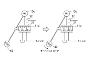
ここで、ステップモータをオーバーストローク位置まで駆動する理由について説明する。図13は変速制御の機械的フィードバック機構の概略図を表す図である。変速比をHi側に変速するときは、プライマリプーリの溝幅を狭くする。よって、プライマリプーリシリンダ室10cに油圧を供給する。まず、ステップモータ40を図中右方に移動させる。これによりスプール31aが右方に移動し、ライン圧ポートを連通させることで油圧が供給され、プライマリプーリの可動円錐板が図中左方に移動し、Hi側に変速する。この可動円錐板の移動によってスプール31aが図中左方に移動し、再度ライン圧ポートを遮断する。よって油圧の供給が停止し変速が完了する。
【0081】
第2実施例における故障検出が許可された状態は、高変速比(オーバードライブ)状態での定常走行である。このとき、プライマリプーリの溝幅は最も狭い状態になっており、更に油圧を供給したとしても変速比が変化することはない。よって、ステップモータ40をオーバーストローク位置まで駆動し、高変速比の状態でライン圧を直接プライマリプーリシリンダ室10cに供給し、プライマリ油圧センサ32によってライン圧を検出できる状態にする。
【0082】
故障判定許可条件が成立し、プライマリ油圧センサ32の検出油圧が安定する所定時間τ1の間、すなわち時刻t2まで油圧の検出を行わない。そして、所定時間τ1経過後、時刻t2からプライマリ油圧センサ32の油圧を検出し、検出された油圧とライン圧指令値との偏差を検出する。この偏差が所定量A以上の状態が所定時間τ2以上継続して検出されるときは、時刻t3において、ライン圧指令値よりも高いライン圧が供給されていることになり、プレッシャレギュレータバルブ60がMAX固着しているとして、故障が判定される。
【0083】
以上説明したように、ライン圧を直接検出する油圧センサを備えておらず、プライマリプーリシリンダ室10cの油圧を検出するプライマリ油圧センサ32によって、走行中にライン圧のMAX側固着を検出することが可能となり、ライン圧の上昇による燃費の悪化を防止することができる。
【0084】
以上、本発明の実施の形態及び第1実施例,第2実施例を説明してきたが、本発明の具体的な構成は本実施の形態に限定されるものではなく、発明の要旨を逸脱しない範囲の設計変更等があっても本発明に含まれる。
【図面の簡単な説明】
【図1】第1実施例におけるVベルト式無段変速機の概略構成図である。
【図2】第1実施例における油圧コントロールユニットおよびCVTコントロールユニットの概念図である。
【図3】第1実施例における前進クラッチと後退ブレーキを締結圧のON/OFFにより締結、解放制御する油圧回路を、ライン圧の制御回路とともに示した図である。
【図4】第1実施例におけるソレノイド駆動デューティとライン圧およびクラッチ元圧との関係を示す線図である。
【図5】第1実施例におけるCVTコントロールユニットのプーリ圧制御部で行われる油圧制御の流れを示すフローチャートである。
【図6】第1実施例における変速比と入力トルクに応じた必要セカンダリ圧のマップである。
【図7】第1実施例における変速比と入力トルクに応じた必要プライマリ圧のマップである。
【図8】第1実施例におけるライン圧フェール判定制御の制御内容を表すフローチャートである。
【図9】第1実施例におけるライン圧フェール判定制御を示すタイムチャートである。
【図10】第2実施例における油圧コントロールユニットおよびCVTコントロールユニットの概念図である。
【図11】第2実施例におけるライン圧フェール判定制御の制御内容を表すフローチャートである。
【図12】第2実施例におけるライン圧フェール判定制御を示すタイムチャートである。
【図13】第2実施例におけるステップモータをオーバーストロークした場合の変速制御弁の位置を表す概略図である。
【符号の説明】
1 エンジン
2 トルクコンバータ
4 前後進切り換え機構
5 無段変速機
6 ディファレンシャルギア
8 前進クラッチ
9 後退ブレーキ
10 プライマリプーリ
10a 可動円錐板
10b 固定円錐板
10c プライマリプーリシリンダ室
11 セカンダリプーリ
11a 可動円錐板
11b 固定円錐板
11c セカンダリプーリシリンダ室
12 Vベルト
13 出力軸
14 アイドラギア
20 CVTコントロールユニット(CVTCU)
21 エンジンコントロールユニット(ECU)
22 オイルポンプ
23 インヒビタスイッチ
24 操作量センサ
25 油温センサ
26 プライマリプーリ速度センサ
27 セカンダリプーリ速度センサ
28 油圧センサ
29 エンジン回転数センサ
30 変速制御弁
31 スプール
32 プライマリ油圧センサ
40 ステップモータ
50 サーボリンク
60 プレッシャレギュレータバルブ(調圧弁)
61 減圧弁
70 クラッチレギュレータバルブ
71 回路
80 2ウェイリニアソレノイド
81 アキュムレータ
81a アキュムピストン
81b アキュムレータスプリング
90 セレクトスイッチングバルブ90
91 アキュムレータ
91a アキュムピストン
91b アキュムレータスプリング
100 油圧コントロールユニット(油圧CU)
201 変速制御部
202 プーリ圧制御部[0001]
TECHNICAL FIELD OF THE INVENTION
The present invention relates to a control device for a belt-type continuously variable transmission.
[0002]
[Prior art]
Conventionally, in a belt-type continuously variable transmission, a target speed ratio (a target pulley ratio) is set based on a vehicle speed and a throttle opening, and the groove width of a primary pulley is variably controlled via a speed change control valve so as to achieve the target speed ratio. By doing so, a stepless speed change is performed. In recent years, it has been particularly desired to improve fuel efficiency from the viewpoint of protecting the global environment. One of them is to set the pulley clamp pressure of the above-described belt-type continuously variable transmission to an optimal value according to the input torque.
[Patent Document 1]
JP-A-11-336578 (refer to
[0003]
[Problems to be solved by the invention]
However, if the pressure regulating valve breaks down and a fail operation that always outputs the maximum pressure due to the fail control is activated, an increase in the engine speed due to an increase in the load on the oil pump causes an increase in the pulley clamp pressure. However, there is a possibility that friction loss may occur due to the setting of, and there is a problem that fuel efficiency is deteriorated.
[0004]
The present invention has been made in view of the above problems, and an object of the present invention is to detect a failure of a pressure regulating valve for regulating a line pressure, in particular, by detecting whether or not pressure regulation can be reliably performed at a low pressure. An object of the present invention is to provide a control device for a belt-type continuously variable transmission that prevents deterioration.
[0005]
[Means for Solving the Problems]
In order to achieve the above object, according to the first aspect of the present invention, a pressure regulating valve that regulates a hydraulic pressure supplied from a hydraulic pressure source, and a pressure regulating valve that controls a pressure regulating state of the pressure regulating valve according to a traveling state of a vehicle. A control means, a primary pulley and a secondary pulley for holding the V-belt, and a hydraulic pressure supplied from the pressure regulating valve to supply the primary pulley or the secondary pulley and change a groove width of the pulley to change a gear ratio. A shift control valve for changing, a secondary pulley oil pressure detecting means for detecting the hydraulic pressure of the secondary pulley, a pressure reducing valve for reducing the hydraulic pressure of the secondary pulley based on a control signal, and a setting based on a vehicle speed and a throttle opening. A speed ratio control means for controlling the speed change control valve and the pressure reducing valve to achieve a target speed ratio. A pressure regulating valve failure determining means for determining a failure of the pressure regulating valve, wherein the pressure regulating valve failure determining means outputs to the speed ratio control means a command for minimizing the pressure reduction amount of the pressure reducing valve; A command to adjust the pressure to the minimum pressure is output to the control means, and when the difference between the hydraulic pressure detected by the secondary pulley oil pressure detection means and the minimum pressure is equal to or more than a predetermined value, the means is determined to be a failure. I do.
[0006]
According to a second aspect of the present invention, in the control device for a belt-type continuously variable transmission according to the first aspect, failure determination permission means for permitting / prohibiting the pressure regulator failure determination is provided, and the failure determination permission means includes: Even when the vehicle is in a stopped state, the hydraulic pressure can be reliably generated, and even if a hydraulic control different from the normal hydraulic control is executed, a means for permitting a failure determination only when the vehicle does not contribute to power transmission is provided. It is characterized by.
[0007]
According to a third aspect of the present invention, in the control device for a belt-type continuously variable transmission according to the first or second aspect, range position detecting means for detecting a range position of a select lever selected by a driver, and detecting a vehicle speed. Vehicle speed detecting means, accelerator pedal opening degree detecting means, engine speed detecting means for detecting engine speed, and oil temperature detecting means for detecting oil temperature in the transmission. The detected range position is a neutral range or a parking range, the detected vehicle speed is a value at which the vehicle can be determined to be stopped, the accelerator pedal is not depressed, and the engine speed is a speed at which hydraulic pressure can be generated. As described above, when the oil temperature is within the range in which the controllability can be ensured, the failure determination is permitted.
[0008]
According to the fourth aspect of the present invention, the pressure regulating valve regulates the hydraulic pressure supplied from the hydraulic pressure source, pressure regulating valve control means for controlling the pressure regulating state of the pressure regulating valve according to the traveling state of the vehicle, and the V belt is sandwiched. A primary pulley and a secondary pulley, a shift actuator driven based on a shift command, a first port connected to a hydraulic supply oil passage for supplying a hydraulic pressure regulated by the pressure regulating valve, and a cylinder chamber of the primary pulley. A second port connected to a hydraulic supply / discharge oil passage communicating therewith; a third port connected to a discharge oil passage discharging the oil in the cylinder chamber of the primary pulley; and a blocking position for blocking communication between the ports. When the speed change actuator is driven on the speed increasing side, the actuator moves to the speed increasing position communicating the first port and the second port. When the speed change actuator is driven on the speed decreasing side, the second port and the third port are moved to the third position. A shift control valve configured to control a hydraulic pressure to be supplied to a cylinder chamber of the primary pulley, and a groove width of the primary pulley to be detected and driven by the shift actuator. A mechanical feedback mechanism for returning the spool to the shut-off position, primary pulley oil pressure detecting means for detecting the oil pressure of the primary pulley, and the shift actuator so as to attain a target gear ratio set based on a vehicle speed and a throttle opening. In a control device for a belt-type continuously variable transmission, comprising a speed ratio control means for controlling and a speed ratio detecting means for detecting a speed ratio, a pressure regulating valve failure determining means for determining a failure of the pressure regulating valve is provided. When the set speed ratio is on the side of the maximum speed increase ratio, the pressure regulating valve failure determining means is Outputting a command to drive the speed change actuator in a direction to connect the first port and the second port, wherein a deviation between a hydraulic pressure detected by the primary pulley hydraulic pressure detecting means and a command value of the pressure regulating valve control means is a predetermined value or more. In the case of (1), a means for judging a failure is provided.
[0009]
According to a fifth aspect of the present invention, in the control device for a belt-type continuously variable transmission according to the fourth aspect, failure determination permission means for permitting / prohibiting the pressure regulator failure determination is provided, and the failure determination permission means comprises: When the gear ratio is the maximum gear ratio and the target gear ratio is the maximum gear ratio, the failure determination is permitted.
[0010]
According to a sixth aspect of the present invention, in the control device for a belt-type continuously variable transmission according to the fourth or fifth aspect, an engine speed detecting unit for detecting an engine speed is provided, and the failure determination unit includes an engine speed detecting unit. When the number is equal to or higher than the number of rotations at which hydraulic pressure can be generated, a failure determination is permitted.
[0011]
Function and effect of the present invention
In the control device for a belt-type continuously variable transmission according to
[0012]
In the control device for a belt-type continuously variable transmission according to the second aspect, the failure determination permitting means is capable of reliably generating the hydraulic pressure when the vehicle is in a stopped state, and that is different from the normal hydraulic control. Even if is executed, a means for permitting a failure determination only when the vehicle does not contribute to power transmission is adopted. That is, a failure is detected by intentionally performing a hydraulic control that is different from a normal hydraulic control. Therefore, a failure can be detected in a state where the safety of the vehicle is ensured.
[0013]
In the control device for the belt-type continuously variable transmission according to the third aspect, the detected range position is the neutral range or the parking range, and when the detected vehicle speed is 0, the vehicle is considered to be in a stopped state. If the accelerator pedal is not depressed, the driver has no intention to start. If the engine speed is higher than the speed at which hydraulic pressure can be generated and the oil temperature is within the range where controllability can be ensured, it is considered that the environment for accurately determining a failure is in place, and Failure can be detected.
[0014]
In the invention described in
In this state, when the deviation between the oil pressure detected by the primary pulley oil pressure detecting means and the command value of the pressure regulating valve control means is equal to or more than a predetermined value, the line pressure is output higher than the command value, and it is determined that a failure has occurred. . Thus, even if the configuration does not include the line pressure detecting means for directly detecting the line pressure, the failure of the pressure regulating valve can be detected.
[0015]
In the control device for a belt-type continuously variable transmission according to the fifth aspect, the failure determination permission means includes: when the speed ratio is the maximum speed ratio side and the target speed ratio is the maximum speed ratio side, By permitting the failure determination, the failure determination is permitted only in the steady traveling in which the driver keeps the traveling state constant. Therefore, from the state in which the speed change actuator is driven to the speed increase ratio side than normal by the failure determination means, for example, the drive to the speed reduction ratio side is performed based on the driver's speed change request, and the responsiveness is not deteriorated. Failures can be detected without affecting the state.
[0016]
In the control device for a belt-type continuously variable transmission according to the sixth aspect, if the engine speed is equal to or higher than the speed at which the hydraulic pressure can be generated, the hydraulic pressure required to determine the failure is secured, and the failure is reliably detected. Can be detected.
[0017]
BEST MODE FOR CARRYING OUT THE INVENTION
Hereinafter, embodiments of the present invention will be described with reference to the drawings.
[0018]
(Embodiment)
First, the configuration will be described.
FIG. 1 is a schematic configuration diagram of a V-belt type continuously variable transmission, and FIG. 2 is a conceptual diagram of a hydraulic control unit and a CVT control unit.
[0019]
In FIG. 1, a continuously
[0020]
The gear ratio of the continuously
[0021]
The primary pulley 10 of the continuously
[0022]
On the other hand, the
[0023]
Here, the primary
[0024]
The drive torque input from the
[0025]
The gear ratio of the continuously
[0026]
As shown in FIG. 2, the
[0027]
The
[0028]
The line pressure control is constituted by a
[0029]
Line pressure P L Are supplied to a
[0030]
The gear ratio between the primary pulley 10 and the
[0031]
The
[0032]
Here, in FIG. 1, the
[0033]
The
[0034]
The pulley
[0035]
Next, the structure of the forward /
A hydraulic circuit that controls engagement and release of the
[0036]
Line pressure P by
[0037]
The
For example, the control is performed based on the map shown in FIG.
[0038]
By the way, line pressure P L Is the minimum value P according to the 2-way linear solenoid drive duty D LMIN And the highest value P LMAX And the clutch base pressure P CO Is the minimum value P according to the 2-way linear solenoid drive duty D CMIN And the highest value P CMAX And changes as shown.
[0039]
Clutch base pressure P CO Is supplied to the
[0040]
[0041]
Therefore, the
[0042]
Next, the operation will be described.
[Normal shift control process]
The normal shift control by the
[0043]
First, in step S1, the actual gear ratio is calculated from the ratio between the primary pulley rotation speed detected by the primary
[0044]
In step S2, the input torque to the continuously
[0045]
Next, in step S3, a required secondary pressure (required secondary pressure) is calculated based on the actual gear ratio and the input torque with reference to the map of FIG.
In this map, the lower the speed ratio (Od side), the lower the hydraulic pressure, and the higher the speed ratio (Lo side), the higher the hydraulic pressure. If the input torque is large, the hydraulic pressure is high, and if the input torque is small, The hydraulic pressure is set low, and is set in advance.
[0046]
In step S4, a required primary pressure (required primary pressure) is calculated based on the actual gear ratio and the input torque with reference to the map of FIG.
In this map, the lower the speed ratio, the lower the hydraulic pressure, the higher the hydraulic pressure, the higher the hydraulic pressure, and the higher the input torque, the higher the hydraulic pressure, and the lower the input torque, the lower the hydraulic pressure. Thus, the gear ratio is set to be relatively high on the small side of the gear ratio and relatively low on the large side of the gear ratio. However, the magnitude relationship between the required primary pressure and the required secondary pressure may be reversed depending on the input torque.
[0047]
Next, in step S5, the primary pressure operation amount, which is the target value of the primary pressure, is calculated by the following equation.
Primary pressure operation amount = required primary pressure + offset amount
Here, the offset amount is a value (added value of the oil pressure) set according to the characteristic of the
[0048]
In step S6, the magnitude relationship between the primary pressure manipulated variable and the required secondary pressure obtained in step S3 is compared and determined. When the primary pressure operation amount is larger, the process proceeds to step S7, and when the required secondary pressure is equal to or more than the primary pressure operation amount, the process proceeds to step S8.
[0049]
In step S7, the line pressure P L This control is ended with the line pressure operation amount, which is the target value of, as the primary pressure operation amount.
[0050]
In step S8, this control is ended with the line pressure operation amount as a necessary secondary pressure.
[0051]
As described above, after the larger of the primary pressure operation amount and the required secondary pressure is determined as the line pressure operation amount (target oil pressure), the control amount (such as the duty signal) for driving the solenoid of the
[0052]
(First embodiment)
Hereinafter, a first embodiment of the present invention will be described with reference to the drawings. In the present embodiment, the case where the
In the configuration of the above-described embodiment, the hydraulic pressure supplied to the primary
[0053]
[Line pressure failure judgment control when vehicle is stopped]
FIG. 8 is a flowchart showing the control contents of the line pressure fail determination control.
[0054]
In
[0055]
In
・ Range signal is N or P range (power is not transmitted)
・ Vehicle speed = 0 (vehicle stopped)
・ Idle state where the accelerator is not depressed (state where the driver does not intend to start)
・ The engine speed is higher than the speed at which line pressure can be output.
・ Oil temperature is within a predetermined oil temperature range (because the viscosity may be high and the controllability may decrease at low temperatures, and the oil balance may be insufficient at high temperatures).
-Each solenoid,
Only when all of the above conditions are satisfied, it is determined that a safe state is ensured even if the hydraulic control is controlled to a state different from the normal state, and a failure determination is permitted (corresponding to
[0056]
In
[0057]
In
[0058]
In
[0059]
In
[0060]
In
[0061]
In
[0062]
In
[0063]
In
[0064]
The above control contents will be described based on the time chart of FIG.
At time t1, when the failure determination permission condition is satisfied, a line pressure MIN control command is output in
[0065]
A predetermined time τ during which the failure determination permission condition is satisfied and the oil pressure detected by the
[0066]
As described above, even if the hydraulic pressure sensor for directly detecting the line pressure is not provided, and only the hydraulic pressure sensor for detecting the hydraulic pressure of the secondary
[0067]
(Second embodiment)
FIG. 10 is a conceptual diagram of a hydraulic control unit and a CVT control unit in the second embodiment. In the first embodiment, only the
[0068]
In the second embodiment, as in the first embodiment, the case where the
[0069]
[Line pressure failure judgment control during vehicle running]
FIG. 11 is a flowchart showing the control contents of the line pressure fail determination control.
[0070]
In
[0071]
In
・ Actual gear ratio <predetermined gear ratio (equivalent to overdrive)
When the actual gear ratio is equivalent to overdrive, as shown in the gear ratio-primary pressure map of FIG. 7, the required primary pressure is low, and accordingly, the line pressure is also controlled to a low value. 5).
・ Target gear ratio <predetermined gear ratio (equivalent to overdrive)
This is because when the target gear ratio is equivalent to overdrive, it can be determined that the shift state is a steady state because it is equivalent to overdrive at the present time (corresponding to claim 5).・ No shift decision
If the vehicle is not running steady at a high gear ratio without crossing the gear shift line in the gear shift map, the gear ratio must be changed according to the driver's intention, and the response by driving the stepping motor overstroke is required. This is to prevent delay.
・ Engine speed> Predetermined value
This is because if the engine speed is equal to or higher than the predetermined value, a state in which a sufficient oil pressure is generated is secured in terms of the oil balance.
・ Secondary oil pressure <Predetermined value
The belt-type continuously variable transmission performs gear shifting with the balance of the belt clamping force of the primary pulley and the secondary pulley, and if the secondary hydraulic pressure is high and if a lower line pressure is supplied to the primary pulley as it is, the gear may shift. It is.
-Each solenoid,
Only when all of the above conditions are satisfied, it is determined that a safe state is secured even if the hydraulic control is controlled to a state different from the normal state, and the failure determination is permitted (the failure determination permission means according to the claims). Equivalent).
[0072]
In
[0073]
In
[0074]
In
[0075]
In
[0076]
In
[0077]
In
[0078]
In
[0079]
The above control contents will be described based on the time chart of FIG.
When the failure determination permission condition is satisfied at time t1, the step motor is driven to the overstroke position in step 203 (corresponding to claim 4).
[0080]
Here, the reason for driving the step motor to the overstroke position will be described. FIG. 13 is a diagram illustrating a schematic diagram of a mechanical feedback mechanism for speed change control. When shifting the gear ratio to the Hi side, the groove width of the primary pulley is reduced. Therefore, the hydraulic pressure is supplied to the primary
[0081]
The state in which the failure detection is permitted in the second embodiment is a steady running in a high gear ratio (overdrive) state. At this time, the groove width of the primary pulley is in the narrowest state, and the gear ratio does not change even if the hydraulic pressure is further supplied. Therefore, the
[0082]
A predetermined time τ during which the failure determination permission condition is satisfied and the hydraulic pressure detected by the primary
[0083]
As described above, the
[0084]
The embodiment of the present invention, the first embodiment, and the second embodiment have been described above, but the specific configuration of the present invention is not limited to the present embodiment and does not depart from the gist of the invention. Even a change in the design of the range is included in the present invention.
[Brief description of the drawings]
FIG. 1 is a schematic configuration diagram of a V-belt type continuously variable transmission according to a first embodiment.
FIG. 2 is a conceptual diagram of a hydraulic control unit and a CVT control unit in the first embodiment.
FIG. 3 is a diagram showing a hydraulic circuit for controlling engagement and release of a forward clutch and a reverse brake by ON / OFF of an engagement pressure together with a line pressure control circuit in the first embodiment.
FIG. 4 is a diagram showing a relationship between a solenoid drive duty, a line pressure, and a clutch base pressure in the first embodiment.
FIG. 5 is a flowchart illustrating a flow of hydraulic control performed by a pulley pressure control unit of the CVT control unit in the first embodiment.
FIG. 6 is a map of a required secondary pressure according to a gear ratio and an input torque in the first embodiment.
FIG. 7 is a map of a required primary pressure according to a gear ratio and an input torque in the first embodiment.
FIG. 8 is a flowchart illustrating control contents of a line pressure fail determination control in the first embodiment.
FIG. 9 is a time chart showing a line pressure fail determination control in the first embodiment.
FIG. 10 is a conceptual diagram of a hydraulic control unit and a CVT control unit in a second embodiment.
FIG. 11 is a flowchart illustrating control contents of a line pressure fail determination control in a second embodiment.
FIG. 12 is a time chart illustrating a line pressure fail determination control in the second embodiment.
FIG. 13 is a schematic diagram showing the position of a shift control valve when the stepping motor is overstroke in the second embodiment.
[Explanation of symbols]
1 engine
2 Torque converter
4 Forward / backward switching mechanism
5 continuously variable transmission
6 Differential gear
8 Forward clutch
9 Reverse brake
10 Primary pulley
10a Movable conical plate
10b Fixed conical plate
10c Primary pulley cylinder chamber
11 Secondary pulley
11a Movable conical plate
11b Fixed conical plate
11c Secondary pulley cylinder chamber
12 V belt
13 Output shaft
14 Idler Gear
20 CVT control unit (CVTCU)
21 Engine control unit (ECU)
22 Oil pump
23 Inhibitor switch
24 Operation amount sensor
25 Oil temperature sensor
26 Primary pulley speed sensor
27 Secondary pulley speed sensor
28 Oil pressure sensor
29 Engine speed sensor
30 Shift control valve
31 spool
32 Primary oil pressure sensor
40 step motor
50 Servo link
60 Pressure regulator valve (pressure regulating valve)
61 Pressure reducing valve
70 Clutch regulator valve
71 circuits
80 2-way linear solenoid
81 accumulator
81a Accumulated piston
81b Accumulator spring
90
91 Accumulator
91a Accumulated piston
91b Accumulator spring
100 Hydraulic control unit (Hydraulic CU)
201 shift control unit
202 Pulley pressure control unit
Claims (6)
車両の走行状態に応じて前記調圧弁の調圧状態を制御する調圧弁制御手段と、
Vベルトを挟持するプライマリプーリおよびセカンダリプーリと、
前記調圧弁から供給される油圧を制御して前記プライマリプーリまたはセカンダリプーリに供給し、前記プーリの溝幅を変更して変速比を変化させる変速制御弁と、
前記セカンダリプーリの油圧を検出するセカンダリプーリ油圧検出手段と、
前記セカンダリプーリの油圧を制御信号に基づいて減圧する減圧弁と、
車速とスロットル開度に基づいて設定される目標変速比となるように前記変速制御弁及び前記減圧弁を制御する変速比制御手段と、
を備えたベルト式無段変速機の制御装置において、
前記調圧弁の故障を判断する調圧弁故障判断手段を設け、
該調圧弁故障判断手段は、前記変速比制御手段に対し減圧弁の減圧量を最小にする指令を出力すると共に、前記調圧弁制御手段に対し最低圧に調圧する指令を出力し、前記セカンダリプーリ油圧検出手段により検出された油圧と前記最低圧との偏差が所定値以上のときは故障と判断する手段としたことを特徴とするベルト式無段変速機の制御装置。A pressure regulating valve for regulating the hydraulic pressure supplied from the hydraulic pressure source,
Pressure regulating valve control means for controlling the pressure regulating state of the pressure regulating valve according to the running state of the vehicle,
A primary pulley and a secondary pulley for holding the V-belt,
A shift control valve that controls a hydraulic pressure supplied from the pressure regulating valve to supply the primary pulley or the secondary pulley, and changes a groove width of the pulley to change a gear ratio;
Secondary pulley oil pressure detection means for detecting the oil pressure of the secondary pulley,
A pressure reducing valve that reduces the hydraulic pressure of the secondary pulley based on a control signal;
Speed ratio control means for controlling the speed change control valve and the pressure reducing valve so as to have a target speed ratio set based on the vehicle speed and the throttle opening;
In the control device of the belt-type continuously variable transmission having
Provision of a pressure regulating valve failure determining means for determining the failure of the pressure regulating valve,
The pressure regulating valve failure determination means outputs a command to minimize the amount of pressure reduction of the pressure reducing valve to the speed ratio control means, and outputs a command to regulate the pressure to the minimum pressure to the pressure regulating valve control means. A control device for a belt-type continuously variable transmission, characterized in that when the deviation between the oil pressure detected by the oil pressure detecting means and the minimum pressure is equal to or more than a predetermined value, it is determined that a failure has occurred.
前記調圧弁故障判断を許可・禁止する故障判断許可手段を設け、
該故障判断許可手段は、車両が停車状態であって、油圧が確実に発生可能であり、かつ、通常の油圧制御と異なる油圧制御を実行したとしても、動力伝達に寄与しないときにのみ故障判断を許可する手段としたことを特徴とするベルト式無段変速機の制御装置。The control device for a belt-type continuously variable transmission according to claim 1,
Provision of a failure determination permission means for permitting / prohibiting the pressure regulator failure determination,
The failure determination permitting means determines the failure only when the vehicle is in a stopped state, the hydraulic pressure can be reliably generated, and even if a hydraulic control different from the normal hydraulic control is executed, it does not contribute to the power transmission. A control device for a belt-type continuously variable transmission, wherein the control device is configured to permit the control of the transmission.
運転者の選択するセレクトレバーのレンジ位置を検出するレンジ位置検出手段と、
車速を検出する車速検出手段と、
アクセルペダル開度検出手段と、
エンジン回転数を検出するエンジン回転数検出手段と、
変速機内の油温を検出する油温検出手段と、
を備え、
前記故障判断許可手段は、検出されたレンジ位置がニュートラルレンジもしくはパーキングレンジであり、検出された車速が車両停止と判断できる値であり、アクセルペダルが踏まれていない状態であり、エンジン回転数が油圧を発生可能な回転数以上であり、油温が制御性の確保可能な領域内であるときは、故障判断を許可することを特徴とするベルト式無段変速機の制御装置。The control device for a belt-type continuously variable transmission according to claim 1 or 2,
Range position detecting means for detecting a range position of a select lever selected by a driver;
Vehicle speed detecting means for detecting a vehicle speed;
Accelerator pedal opening detection means;
Engine speed detecting means for detecting the engine speed,
Oil temperature detecting means for detecting the oil temperature in the transmission,
With
The failure determination permitting means is such that the detected range position is a neutral range or a parking range, the detected vehicle speed is a value that can be determined to be a vehicle stop, the accelerator pedal is not depressed, and the engine speed is lower. A control device for a belt-type continuously variable transmission, wherein a failure determination is permitted when the rotation speed is equal to or higher than a rotation speed at which hydraulic pressure can be generated and the oil temperature is within a region where controllability is ensured.
車両の走行状態に応じて前記調圧弁の調圧状態を制御する調圧弁制御手段と、
Vベルトを挟持するプライマリプーリおよびセカンダリプーリと、
変速指令に基づいて駆動する変速アクチュエータと、
前記調圧弁により調圧された油圧を供給する油圧供給油路と接続する第1ポートと、前記プライマリプーリのシリンダ室と連通する油圧供給・排出油路と接続する第2ポートと、前記プライマリプーリのシリンダ室の油を排出する排出油路と接続する第3ポートと、各ポートの連通を遮断する遮断位置から、前記変速アクチュエータの増速側駆動のときは前記第1ポートと前記第2ポートを連通する増速位置に移動し、減速側駆動のときは前記第2ポートと前記第3ポートを連通する減速位置に移動するスプールから構成され、前記プライマリプーリのシリンダ室に供給する油圧を制御する変速制御弁と、
前記プライマリプーリの溝幅を検出し、前記変速アクチュエータにより駆動された前記スプールを遮断位置に復帰するメカニカルフィードバック機構と、
前記プライマリプーリの油圧を検出するプライマリプーリ油圧検出手段と、
車速とスロットル開度に基づいて設定される目標変速比となるように前記変速アクチュエータを制御する変速比制御手段と、
変速比を検出する変速比検出手段と、
を備えたベルト式無段変速機の制御装置において、
前記調圧弁の故障を判断する調圧弁故障判断手段を設け、
前記調圧弁故障判断手段は、検出された変速比が最増速比側のときに、前記変速比制御手段に対し前記変速アクチュエータを前記第1ポートと第2ポートを連通する方向に駆動する指令を出力し、前記プライマリプーリ油圧検出手段により検出された油圧と前記調圧弁制御手段の指令値との偏差が所定値以上のときは、故障と判断する手段としたことを特徴とするベルト式無段変速機の制御装置。A pressure regulating valve for regulating the hydraulic pressure supplied from the hydraulic pressure source,
Pressure regulating valve control means for controlling the pressure regulating state of the pressure regulating valve according to the running state of the vehicle,
A primary pulley and a secondary pulley for holding the V-belt,
A shift actuator driven based on a shift command;
A first port connected to a hydraulic supply oil passage for supplying a hydraulic pressure adjusted by the pressure regulating valve; a second port connected to a hydraulic supply / discharge oil passage communicating with a cylinder chamber of the primary pulley; A third port connected to a discharge oil passage for discharging oil from the cylinder chamber, and a first port and a second port when the speed change actuator is driven on a speed increasing side from a blocking position for blocking communication between the ports. A spool that moves to a deceleration position that communicates with the second port and the third port when driving on the deceleration side, and controls a hydraulic pressure that is supplied to a cylinder chamber of the primary pulley. A speed change control valve,
A mechanical feedback mechanism that detects a groove width of the primary pulley and returns the spool driven by the speed change actuator to a blocking position;
Primary pulley oil pressure detection means for detecting the oil pressure of the primary pulley,
Speed ratio control means for controlling the speed change actuator such that the target speed ratio is set based on the vehicle speed and the throttle opening;
Speed ratio detecting means for detecting a speed ratio,
In the control device of the belt-type continuously variable transmission having
Provision of a pressure regulating valve failure determining means for determining the failure of the pressure regulating valve,
The pressure regulating valve failure determination unit is configured to instruct the speed ratio control unit to drive the speed change actuator in a direction to connect the first port and the second port when the detected speed ratio is the maximum speed ratio side. And when the deviation between the oil pressure detected by the primary pulley oil pressure detecting means and the command value of the pressure regulating valve control means is equal to or greater than a predetermined value, means for judging a failure is provided. Control device for step transmission.
前記調圧弁故障判断を許可・禁止する故障判断許可手段を設け、
該故障判断許可手段は、変速比が最増速比側であって、かつ、目標変速比が最増速比側のときは、故障判断を許可することを特徴とするベルト式無段変速機の制御装置。The control device for a belt-type continuously variable transmission according to claim 4,
Provision of a failure determination permission means for permitting / prohibiting the pressure regulator failure determination,
The belt type continuously variable transmission, wherein the failure determination permitting means permits the failure determination when the speed ratio is on the maximum speed increase ratio side and the target speed ratio is on the maximum speed increase ratio side. Control device.
エンジン回転数を検出するエンジン回転数検出手段を設け、
前記故障判断手段は、エンジン回転数が油圧を発生可能な回転数以上のときは、故障判断を許可することを特徴とするベルト式無段変速機の制御装置。The control device for a belt-type continuously variable transmission according to claim 4 or 5,
An engine speed detecting means for detecting the engine speed is provided,
The control device for a belt-type continuously variable transmission, wherein the failure determination means permits the failure determination when the engine rotation speed is equal to or higher than a rotation speed at which hydraulic pressure can be generated.
Priority Applications (1)
| Application Number | Priority Date | Filing Date | Title |
|---|---|---|---|
| JP2002285497A JP4553549B2 (en) | 2002-09-30 | 2002-09-30 | Control device for belt type continuously variable transmission |
Applications Claiming Priority (1)
| Application Number | Priority Date | Filing Date | Title |
|---|---|---|---|
| JP2002285497A JP4553549B2 (en) | 2002-09-30 | 2002-09-30 | Control device for belt type continuously variable transmission |
Publications (2)
| Publication Number | Publication Date |
|---|---|
| JP2004124960A true JP2004124960A (en) | 2004-04-22 |
| JP4553549B2 JP4553549B2 (en) | 2010-09-29 |
Family
ID=32278785
Family Applications (1)
| Application Number | Title | Priority Date | Filing Date |
|---|---|---|---|
| JP2002285497A Expired - Fee Related JP4553549B2 (en) | 2002-09-30 | 2002-09-30 | Control device for belt type continuously variable transmission |
Country Status (1)
| Country | Link |
|---|---|
| JP (1) | JP4553549B2 (en) |
Cited By (7)
| Publication number | Priority date | Publication date | Assignee | Title |
|---|---|---|---|---|
| JP2006200549A (en) * | 2005-01-18 | 2006-08-03 | Fujitsu Ten Ltd | Control method for continuously variable transmission and its device |
| JP2007270937A (en) * | 2006-03-31 | 2007-10-18 | Fujitsu Ten Ltd | Control device for continuously variable transmission |
| US20110118066A1 (en) * | 2008-12-02 | 2011-05-19 | Toyota Jidosha Kabushiki Kaisha | Sheave positioning device |
| JP2014062582A (en) * | 2012-09-20 | 2014-04-10 | Mazda Motor Corp | Control method for power train system, and power train system |
| DE102014103716A1 (en) | 2013-03-27 | 2014-10-02 | Fuji Jukogyo Kabushiki Kaisha | Diagnostic device for a hydraulic pressure control actuator |
| WO2016152333A1 (en) * | 2015-03-20 | 2016-09-29 | ジヤトコ株式会社 | Transmission control device and transmission control method |
| WO2019004166A1 (en) * | 2017-06-28 | 2019-01-03 | ジヤトコ株式会社 | Control device for vehicle and control method for vehicle |
Citations (9)
| Publication number | Priority date | Publication date | Assignee | Title |
|---|---|---|---|---|
| JPH01269620A (en) * | 1988-04-21 | 1989-10-27 | Mazda Motor Corp | Controller for belt type continuously variable transmission |
| JPH03181663A (en) * | 1989-12-09 | 1991-08-07 | Fuji Heavy Ind Ltd | Controller for continuously variable transmission |
| JPH06185605A (en) * | 1992-12-17 | 1994-07-08 | Toyota Motor Corp | Oil pressure controlling device of vehicular belt-type continuously variable transmission |
| JPH08178050A (en) * | 1994-12-27 | 1996-07-12 | Nissan Motor Co Ltd | Speed change control device for v-belt type continuously variable transmission |
| JPH09217800A (en) * | 1996-02-15 | 1997-08-19 | Nissan Motor Co Ltd | Hydraulic controller of transmission |
| JPH09250370A (en) * | 1996-03-18 | 1997-09-22 | Nissan Motor Co Ltd | Fail-safe control device for continuous variable transmission |
| JP2000154866A (en) * | 1998-11-19 | 2000-06-06 | Toyota Central Res & Dev Lab Inc | Hydraulic controller of continuously variable transmission for vehicle |
| JP2001214970A (en) * | 1999-11-22 | 2001-08-10 | Mitsubishi Motors Corp | Transmission control device for hydraulic continuously variable transmission for vehicle |
| JP2001330117A (en) * | 2000-05-19 | 2001-11-30 | Toyota Motor Corp | Hydraulic controller for transmission |
-
2002
- 2002-09-30 JP JP2002285497A patent/JP4553549B2/en not_active Expired - Fee Related
Patent Citations (9)
| Publication number | Priority date | Publication date | Assignee | Title |
|---|---|---|---|---|
| JPH01269620A (en) * | 1988-04-21 | 1989-10-27 | Mazda Motor Corp | Controller for belt type continuously variable transmission |
| JPH03181663A (en) * | 1989-12-09 | 1991-08-07 | Fuji Heavy Ind Ltd | Controller for continuously variable transmission |
| JPH06185605A (en) * | 1992-12-17 | 1994-07-08 | Toyota Motor Corp | Oil pressure controlling device of vehicular belt-type continuously variable transmission |
| JPH08178050A (en) * | 1994-12-27 | 1996-07-12 | Nissan Motor Co Ltd | Speed change control device for v-belt type continuously variable transmission |
| JPH09217800A (en) * | 1996-02-15 | 1997-08-19 | Nissan Motor Co Ltd | Hydraulic controller of transmission |
| JPH09250370A (en) * | 1996-03-18 | 1997-09-22 | Nissan Motor Co Ltd | Fail-safe control device for continuous variable transmission |
| JP2000154866A (en) * | 1998-11-19 | 2000-06-06 | Toyota Central Res & Dev Lab Inc | Hydraulic controller of continuously variable transmission for vehicle |
| JP2001214970A (en) * | 1999-11-22 | 2001-08-10 | Mitsubishi Motors Corp | Transmission control device for hydraulic continuously variable transmission for vehicle |
| JP2001330117A (en) * | 2000-05-19 | 2001-11-30 | Toyota Motor Corp | Hydraulic controller for transmission |
Cited By (11)
| Publication number | Priority date | Publication date | Assignee | Title |
|---|---|---|---|---|
| JP2006200549A (en) * | 2005-01-18 | 2006-08-03 | Fujitsu Ten Ltd | Control method for continuously variable transmission and its device |
| JP2007270937A (en) * | 2006-03-31 | 2007-10-18 | Fujitsu Ten Ltd | Control device for continuously variable transmission |
| US20110118066A1 (en) * | 2008-12-02 | 2011-05-19 | Toyota Jidosha Kabushiki Kaisha | Sheave positioning device |
| US9394992B2 (en) * | 2008-12-02 | 2016-07-19 | Toyota Jidosha Kabushiki Kaisha | Sheave positioning device |
| JP2014062582A (en) * | 2012-09-20 | 2014-04-10 | Mazda Motor Corp | Control method for power train system, and power train system |
| DE102014103716A1 (en) | 2013-03-27 | 2014-10-02 | Fuji Jukogyo Kabushiki Kaisha | Diagnostic device for a hydraulic pressure control actuator |
| DE102014103716B4 (en) * | 2013-03-27 | 2020-03-26 | Subaru Corporation | Diagnostic device for a hydraulic pressure control actuator |
| WO2016152333A1 (en) * | 2015-03-20 | 2016-09-29 | ジヤトコ株式会社 | Transmission control device and transmission control method |
| WO2019004166A1 (en) * | 2017-06-28 | 2019-01-03 | ジヤトコ株式会社 | Control device for vehicle and control method for vehicle |
| CN110770478A (en) * | 2017-06-28 | 2020-02-07 | 加特可株式会社 | Vehicle control device and vehicle control method |
| CN110770478B (en) * | 2017-06-28 | 2021-03-19 | 加特可株式会社 | Vehicle control device and vehicle control method |
Also Published As
| Publication number | Publication date |
|---|---|
| JP4553549B2 (en) | 2010-09-29 |
Similar Documents
| Publication | Publication Date | Title |
|---|---|---|
| KR100409410B1 (en) | Hydraulic control system for a continuously variable ransmission | |
| JP4762875B2 (en) | Shift control device for belt type continuously variable transmission | |
| US6217469B1 (en) | Control system for continuously variable transmission | |
| JP4593486B2 (en) | Shift control device for belt type continuously variable transmission | |
| JP3993489B2 (en) | Belt slip prevention device for belt type continuously variable transmission | |
| JP2004124959A (en) | Controller for automatic transmission | |
| JP3732817B2 (en) | Control device for automatic transmission | |
| KR100510803B1 (en) | Controlling device of automatic transmission | |
| US7140991B2 (en) | Shift control system, and control apparatus and method for belt-type continuously variable transmission | |
| JP2004124961A (en) | Variable speed hydraulic pressure controller for belt type continuously variable transmission | |
| JP3905445B2 (en) | Hydraulic control device for V-belt type continuously variable transmission | |
| JP4553549B2 (en) | Control device for belt type continuously variable transmission | |
| JP4124625B2 (en) | Control device for continuously variable transmission | |
| US20080096719A1 (en) | Hydraulic control device for continuously variable transmisson | |
| JP4148796B2 (en) | Control device for continuously variable transmission | |
| JP2004125063A (en) | Controller for belt type continuously variable transmission | |
| JP2004084786A (en) | Line pressure controller for continuously variable transmission | |
| JP2008106813A (en) | Hydraulic control device of belt continuously variable transmission for vehicle | |
| JP4101563B2 (en) | Slip prevention device for continuously variable transmission for vehicle | |
| JP3896754B2 (en) | Shift control device for continuously variable transmission | |
| JP2004068900A (en) | Variable speed actuator controlling device in continuously variable transmission | |
| JP2004124967A (en) | Controller for belt type continuously variable transmission | |
| JP2006097811A (en) | Line pressure control system in belt-type continuously variable transmission |
Legal Events
| Date | Code | Title | Description |
|---|---|---|---|
| A621 | Written request for application examination |
Free format text: JAPANESE INTERMEDIATE CODE: A621 Effective date: 20040819 |
|
| RD04 | Notification of resignation of power of attorney |
Free format text: JAPANESE INTERMEDIATE CODE: A7424 Effective date: 20051110 |
|
| A977 | Report on retrieval |
Free format text: JAPANESE INTERMEDIATE CODE: A971007 Effective date: 20070913 |
|
| A131 | Notification of reasons for refusal |
Free format text: JAPANESE INTERMEDIATE CODE: A131 Effective date: 20071002 |
|
| A521 | Written amendment |
Free format text: JAPANESE INTERMEDIATE CODE: A523 Effective date: 20071203 |
|
| A131 | Notification of reasons for refusal |
Free format text: JAPANESE INTERMEDIATE CODE: A131 Effective date: 20090407 |
|
| A521 | Written amendment |
Free format text: JAPANESE INTERMEDIATE CODE: A523 Effective date: 20090605 |
|
| A131 | Notification of reasons for refusal |
Free format text: JAPANESE INTERMEDIATE CODE: A131 Effective date: 20100323 |
|
| A521 | Written amendment |
Free format text: JAPANESE INTERMEDIATE CODE: A523 Effective date: 20100521 |
|
| TRDD | Decision of grant or rejection written | ||
| A01 | Written decision to grant a patent or to grant a registration (utility model) |
Free format text: JAPANESE INTERMEDIATE CODE: A01 Effective date: 20100713 |
|
| A01 | Written decision to grant a patent or to grant a registration (utility model) |
Free format text: JAPANESE INTERMEDIATE CODE: A01 |
|
| A61 | First payment of annual fees (during grant procedure) |
Free format text: JAPANESE INTERMEDIATE CODE: A61 Effective date: 20100713 |
|
| FPAY | Renewal fee payment (event date is renewal date of database) |
Free format text: PAYMENT UNTIL: 20130723 Year of fee payment: 3 |
|
| R150 | Certificate of patent or registration of utility model |
Ref document number: 4553549 Country of ref document: JP Free format text: JAPANESE INTERMEDIATE CODE: R150 Free format text: JAPANESE INTERMEDIATE CODE: R150 |
|
| FPAY | Renewal fee payment (event date is renewal date of database) |
Free format text: PAYMENT UNTIL: 20130723 Year of fee payment: 3 |
|
| FPAY | Renewal fee payment (event date is renewal date of database) |
Free format text: PAYMENT UNTIL: 20140723 Year of fee payment: 4 |
|
| R250 | Receipt of annual fees |
Free format text: JAPANESE INTERMEDIATE CODE: R250 |
|
| LAPS | Cancellation because of no payment of annual fees |