JP2004122601A - Image processing device - Google Patents
Image processing device Download PDFInfo
- Publication number
- JP2004122601A JP2004122601A JP2002290615A JP2002290615A JP2004122601A JP 2004122601 A JP2004122601 A JP 2004122601A JP 2002290615 A JP2002290615 A JP 2002290615A JP 2002290615 A JP2002290615 A JP 2002290615A JP 2004122601 A JP2004122601 A JP 2004122601A
- Authority
- JP
- Japan
- Prior art keywords
- distributed
- information
- image forming
- image
- Prior art date
- Legal status (The legal status is an assumption and is not a legal conclusion. Google has not performed a legal analysis and makes no representation as to the accuracy of the status listed.)
- Pending
Links
Images


Abstract
Description
【0001】
【発明の属する技術分野】
本発明は、ホストコンピュータからの印刷ジョブを他の画像形成装置と並列に分散処理可能な画像処理装置に関するものである。
【0002】
【従来の技術】
従来、ホストコンピュータから複数の画像形成装置へ印刷データを送信し、複数の画像形成装置で分散して印刷を行う分散印刷システムが知られている(例えば、特許文献(特開平11−305966号公報)参照)。
【0003】
例えばある印刷データを10部印刷したい場合、ホストコンピュータから、片方の画像形成装置に5部、もう片方の画像形成装置へは5部印刷するよう指令した場合、短時間で目的の印刷物を得ることができる。また、分散する画像形成装置の台数が増えれば、その分短時間で目的の印刷物を得ることができる。
【0004】
【発明が解決しようとする課題】
しかしながら、上述した従来技術においては下記のような問題があった。
【0005】
即ち、ホストコンピュータから複数の画像形成装置へ印刷データを送信した後、分散された各画像形成装置から印刷物を回収する場合、分散された各画像形成装置の名称、場所等をあらかじめ覚えておくか、メモを取っておかなければならないという手間があり、分散出力されたジョブを回収する際に、ユーザが煩雑な判別確認処理が必要となり、利便性が損なわれてしまう等の問題点があった。
【0006】
また、このような問題は、分散出力する台数が多くなるほどさらに厄介な負担をユーザに強いる結果となり、その改善が切望されている。
【0007】
本発明は、上記の問題点を解決するためになされたもので、ユーザが分散出力されていることを容易に確認できるようにするとともに、分散出力がどの画像形成装置において行われたかを容易に確認できるようにする。
【0008】
また、ユーザが分散出力が過去にどのように行われたかをいつでも確認できるようにすることを目的とする。
【0009】
【課題を解決するための手段】
本発明に係る第1の発明は、ホストコンピュータ(図1に示すホストコンピュータ12に相当)からの印刷ジョブを他の画像形成装置と並列に分散処理可能な画像処理装置であって、前記ホストコンピュータから送信される印刷命令および画像データを受信して印刷処理する印刷処理手段(図1に示すPDL展開部8に相当)と、前記ホストコンピュータから複数の画像形成装置へ分散印刷を行っていることを示す情報を受信する分散印刷情報受信手段(図1に示すネットワーク処理部7に相当)と、前記分散印刷情報受信手段により受信した分散印刷情報を操作部に表示する分散印刷情報表示手段(図1に示す操作部500に相当)と、を有することを特徴とする。
【0010】
【発明の実施の形態】
〔第1実施形態〕
図1は、本発明に係る画像形成装置を適用可能な画像処理システムの一例を説明するブロック図であり、画像処理装置と周辺機器とが公衆回線網またはネットワークを介して通信可能な画像処理システム例に対応する。
【0011】
図1において、画像形成装置9は、リーダ部1と、プリンタ部2と、コントローラ部3からなり、コントローラ部3は、モデム通信部4、ネットワーク処理部7、PDL展開部8、コア部10を有する。
【0012】
リーダ部1は、画像形成装置(プリンタ部)にセットされた原稿の画像を読み取り、原稿画像に応じた画像データを、コア部10を通じて、プリンタ部2へ出力する。プリンタ部2は、リーダ部1からの画像データに応じた画像を記録紙上に記録する。
【0013】
コンピュータ11はパーソナルコンピュータまたはワークステーション(PC/WS)であり、例えば、そこからPDLプリントデータを、ネットワーク16、ネットワーク処理部7を通じて、コア部10に流し、PDL展開部8でPDLデータをプリンタ部2で記録できる画像データに展開し、コア部10を通じて、プリンタ部2でプリントする。
【0014】
14は他のファックス装置であり、例えばリーダ部1で読み取った原稿画像を、コア部10、モデム通信部4を経由し、公衆回線網15を通じてファックス送信する。あるいは、他のファックス装置14からの画像データを、公衆回線網15、モデム通信部4、コア部10を通じて受信し、プリンタ部2で受信画像をプリントする。
【0015】
コンピュータ12はパーソナルコンピュータまたはワークステーション(PC/WS)で、本発明のホストコンピュータに該当する。
【0016】
画像形成装置13は、分散印刷を行うために使用され、内部構成は、画像形成装置9と全く同じである。
【0017】
例えばホストコンピュータ11から印刷命令、および画像データを画像形成装置9、画像形成装置13に送信し、分散印刷を行う。なお、図1に示す構成は一例であり、本発明の適用可能なシステムが図示のシステム構成に限定されるものではない。
【0018】
図2は、図1に示したプリンタ部2の構成を説明する概略断面図である。
【0019】
図2において、プリンタ部2は、画像形成装置本体(複写装置本体)100、デッキ150、循環式自動原稿送り装置(RDF)180から大略構成されている。
【0020】
画像形成装置本体100は、プラテンガラス101、スキャナ102、原稿照明ランプ103、走査ミラー104、105、106、レンズ108、CCDセンサ(イメージセンサ部)109、感光体ドラム110、1次帯電器112、前露光ランプ114、クリーニング装置116、転写帯電器118、露光制御部120、現像器121、転写ベルト130、上段カセット131、下段カセット132、ピックアップローラ133、134、給紙ローラ135、136、レジストローラ137、吸着帯電ローラ138、転写ベルトローラ170、定着前帯電器139、140、定着器141、排紙ローラ142、排紙フラッパ154、反転パス155、再給紙トレイ156、多重フラッパ157、搬送パス158、給紙ローラ159、経路160、排出ローラ161、第1の送りローラ162、第2の送りローラ162a、反転ローラ163を備えている。
【0021】
上記構成を詳述すると、図1におけるリーダ部1は、図2のプラテンガラス101〜CCDセンサ109に対応し、プリンタ部2は、図2の感光体ドラム110〜反転ローラ163に対応する。
【0022】
まず、リーダ部1について詳述する。
【0023】
プラテンガラス101は、原稿載置台である。スキャナ102は、原稿照明ランプ103、走査ミラー104等で構成され、不図示のモータにより所定方向に往復走査されることにより、原稿の反射光107を、走査ミラー104〜106を介してレンズ108を透過させてCCDセンサ109に結像する。
【0024】
CCDセンサ109で、電気信号に変換され、CCDセンサ109付近の、図示しないスキャナ画像処理部によって、A/D変換、シェーディング補正が行われ、後述するコア部10のゲートアレイ326を介して、メモリ324にデジタル画像データとして蓄積される。
【0025】
次にプリンタ部2について詳述する。露光制御部120は、レーザ、ポリゴンスキャナ等で構成されており、後述するコア部10のメモリ324に蓄積されたデジタル出力画像データをメモリから読み出し、コア部10のゲートアレイ326が、デジタル画像データからビデオ信号に変換し、I/F327を通じてプリンタ部に送る。
【0026】
そして、そのビデオ信号に基づいて変調されたレーザ光129を、感光体ドラム110に照射する。感光体ドラム110の回りには、1次帯電器112、現像器121、転写帯電器118、クリーニング装置116、前露光ランプ114が装備されている。
【0027】
感光体ドラム110を中心とした画像形成部126において、感光体ドラム110は、不図示のモータにより図中矢印方向に回転しており、1次帯電器112により所望の電位に帯電された後、露光制御部120からのレーザ光129が照射され、静電潜像が形成される。
【0028】
一方、上段カセット131或いは下段カセット132からピックアップローラ133、134により給紙された転写紙は、給紙ローラ135、136により本体に送られ、レジストローラ137により転写ベルトに給送され、可視化されたトナー像が転写帯電器118により転写紙に転写される。転写後の感光体ドラム110は、クリーニング装置116により残留トナーが清掃され、前露光ランプ114により残留電荷が消去される。転写後の転写紙は、転写ベルト130から分離され、定着前帯電器139、140によりトナーが再帯電され、定着器141に送られ加圧、加熱により定着され、排紙ローラ142により本体100の外に排出される。
【0029】
吸着帯電ローラ138は、レジストローラ137から送られた転写紙を転写ベルト130に吸着させる。転写ベルトローラ170は、転写ベルト130の回転に用いられると同時に、吸着帯電ローラ138と対になって、転写ベルト130に転写紙を吸着帯電させる。
【0030】
画像形成装置本体100には、例えば4000枚の転写紙を収納し得るデッキ150が装備されている。デッキ150のリフタ151は、給紙ローラ152に転写紙が常に当接するように転写紙の量に応じて上昇する。また、画像形成装置本体100には、例えば100枚の転写紙を収容し得るマルチ手差し給紙部153が装備されている。
【0031】
排紙フラッパ154は、両面記録側ないし多重記録側と排紙側の経路を切り替える。排紙ローラ142から送り出された転写紙は、この排紙フラッパ154により両面記録側ないし多重記録側に切り替えられる。
【0032】
多重フラッパ157は、両面記録と多重記録の経路を切り替えるものであり、これを左方向に倒すことにより、反転パス155を介さず、直接、搬送パス158に転写紙を導く。給紙ローラ159は、経路160を通じて転写紙を感光体ドラム110側に給紙する。
【0033】
排出ローラ161は、排紙フラッパ154の近傍に配置されて、この排紙フラッパ154により排出側に切り替えられた転写紙を機外に排出する。両面記録(両面複写)時には、排紙フラッパ154を上方に上げて、多重フラッパ157を右に倒し、記録(複写)済みの転写紙を反転パス155を介した後、多重フラッパ157を左に倒し、搬送パス158を介して裏返した状態で再給紙トレイ156に格納する。
【0034】
また、多重記録(多重複写)時には、排紙フラッパ154を上方に上げて、多重フラッパ157を左に倒し、記録(複写)済みの転写紙を搬送パス158を介した後、再給紙トレイ156に格納する。再給紙トレイ156に格納されている転写紙が、下から1枚ずつ給紙ローラ159により経路160を介して本体のレジストローラ137に導かれる。
【0035】
本体から転写紙を反転して排出する時には、排紙フラッパ154を上方へ上げ、多重フラッパ157を右方向へ倒し、記録(複写)済みの転写紙を搬送パス155側へ搬送し、転写紙の後端が第1の送りローラ162を通過した後に、反転ローラ163によって第2の送りローラ162a側へ搬送し、排出ローラ161によって転写紙を裏返して機外へ排出する。また、機外へ排出された転写紙は、フィニッシャ190に搬送される。
【0036】
190はフィニッシャであり、画像形成装置本体100で印刷された転写紙をスタックするものである。パス193は、画像形成装置本体100で印刷された転写紙を受け取る経路である。ローラ197は、パス193から搬送された転写紙を、パス195あるいはパス196に送り出すものである。パス195へ送り出すには、排紙フラッパ194を下方に移動し、パス196へ送り出すには、排紙フラッパ194を上方に移動させる。そして、パス196を通った場合は、ローラ198によって、ビン192に排紙される。
【0037】
パス195を通った場合は、そのままビン191に排紙される。例えば、コピーを行った場合は、転写紙をビン191に排紙し、PDLプリントを行った場合は、ビン192に排紙することで、ユーザの利便性が上がる。
【0038】
図3は、図1に示したコア部10の構成を示すブロック図である。
【0039】
図3において、コア部10は、インタフェース部(I/F)320、322、328、327、データ処理部321、326、CPU323(各制御手段)、メモリ324を備えている。
【0040】
上記構成を詳述すると、リーダ部1からの画像データは、I/F322を介してデータ処理部321へ転送される。データ処理部321では、画像の回転処理や変倍処理などの画像処理を行う。また、データ処理部321へ転送された画像データは、CPU323を通じて、メモリ324にデジタル画像データとして蓄積される。
【0041】
また、操作部500からの制御コマンドに応じて、CPU323、データ処理部326、I/F327を通じて、プリンタ部2へ転送される。または、I/F320を介してモデム通信部4、ネットワーク処理部7へ転送される。
【0042】
また、ネットワーク処理部7を介して入力された画像を表すコードデータは、I/F320を介して、CPU323へ転送され、CPU323が、PDLコードであると判定した場合、PDLコードを、I/F320を通じて、PDL展開部8へ転送されて、そこで、画像ビットマップデータに展開される。この画像ビットマップデータは、I/F320、CPU323を通じて、メモリ324へ蓄積されていく。その後、CPU323、データ処理部326、I/F327を通じて、プリンタ部2へ転送され、プリントされる。
【0043】
モデム通信部4からのファックス画像データは、I/F320、CPU323を介して、データ処理部326へ転送された後、I/F327を介して、プリンタ部2へ転送される。
【0044】
CPU323は、メモリ324に記憶されている制御プログラム、及びI/F328経由で操作部500から受けた制御コマンドに従って、上記のような制御を行う。また、メモリ324はCPU323の作業領域としても使われる。
【0045】
このように、本画像形成装置では、コントローラ部3のコア部10を中心に、原稿画像の読み取り、画像のプリント、画像の送受信、画像の保存、コンピュータからのデータの入出力などの機能を複合させた処理を行うことが可能である。
【0046】
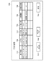
図4は、図1に示した操作部500の画面構成例を示す平面図である。なお、画面はタッチパネルとなっており、それぞれ表示される機能の枠内を触れることにより、その機能が実行される。
【0047】
図4において、コピーモードキー524は、複写動作を行う場合に押すキーである。そして、このコピーモードキー524が押されたときに、図4に示すコピーモード画面530を表示する。拡張機能キー501は、このキーを押すことによって両面複写、多重複写、移動、綴じ代の設定、枠消しの設定等のモードに入る。
【0048】
540は分散印刷情報表示手段として機能するステータスラインであり、機器の状態や印刷情報を示すメッセージを表示する。本表示例は、分散印刷を実行した例を示しており、ホストコンピュータから、“suzuki−ichiro”というユーザ名で、ファイル“会議資料.doc”を、表示している画像形成装置で5部、他の画像形成装置である“総務課iR3300”で5部プリントしていることを示している。
【0049】
画像モードキー502は、複写画像に対して網掛け、影付け、トリミング、マスキングを行うための設定モードを設定する際に押下する。ユーザモードキー503は、モードメモリの登録、標準モード画面の設定が行える。
【0050】
応用ズームキー504は、原稿のX方向、Y方向を独立に変倍するモード、原稿サイズと複写サイズから変倍率を計算するズームプログラムのモードを設定する際に押下する。M1キー505、M2キー506、M3キー507は、それぞれに登録されたモードメモリを呼び出す際に押すキーである。508はコールキーである。
【0051】
オプションキー509は、フィルムから直接複写するため、フィルムプロジェクタ等のオプション機能の設定を行うキーである。
【0052】
ソータキー510は、ソート、ノンソート、グループの設定を行うキーである。原稿混載キー511は、原稿フィーダにA4サイズとA3サイズ、またはB5サイズとB4サイズの原稿を一緒にセットする際に押すキーである。
【0053】
等倍キー512は、複写倍率を100%にする際に押すキーである。縮小キー514、拡大キー515は、定型の縮小、拡大を行う際に押すキーである。用紙選択キー513は、複写用紙の選択を行う際に押すキーである。濃度キー518、520は、キー518を押す毎に濃く複写され、キー520を押す毎に薄く複写される。濃度表示517は、濃度キー518、520を押すと表示が左右に変化する。AEキー519は、新聞のように地肌の濃い原稿を自動濃度調整複写するときに押すキーである。516はズームキーである。
【0054】
HiFiキー521は、写真原稿のように中間調の濃度が濃い原稿の複写の際に押すキーである。文字強調キー522は、文字原稿の複写で文字を際だたせたい場合に押すキーである。ガイドキー(?キー)523は、あるキーの機能がわからないとき押すキーであり、そのキーの説明が表示される。ファックスキー525は、ファックスを行うときに押すキーであり、ファイルキー526は、ファイルデータを出力したいときに押すキーである。
【0055】
プリンタキー527は、プリントの濃度を変更する、あるいは、リモートのホストコンピュータからのPDLデータのプリント出力詳細情報を参照したい場合に押すキーである。528はIDキーである。
【0056】
処理続行キー550は、ホストコンピュータからの印刷データについて1部だけ印刷し、画像データを保持したままとしたとき、ユーザがその印刷物を見てOK、つまり意図した印刷物だったなら処理続行キー550を押し、たとえばその画像形成装置で5部印刷するなら残り4部を印刷する。または、他の画像形成装置でも5部印刷するなら、処理続行キー550を押したタイミングで、他の画像形成装置へその旨通信し、それを受けた画像形成装置は、保持している画像データについて5部印刷する。
【0057】
処理中止キー551は、ホストコンピュータからの印刷データについて1部だけ印刷し、画像データを保持したままとしたとき、ユーザがその印刷物を見てNG、つまり意図した印刷でなかったなら処理中止キー551を押し、残りの印刷部数、たとえば5部印刷する予定であったなら残り4部の印刷について中止する。または、他の画像形成装置でも5部印刷する予定だったなら、処理中止キー551を押したタイミングで、他の画像形成装置へその旨通信し、それを受けた画像形成装置は、保持している画像データについて予定していた印刷を中止する。
【0058】
なお、処理続行キー550、処理中止キー551は、1部プリントが終わった時点で操作部に表示され、押下が可能となる。
【0059】
560は本発明に関わる履歴キーであり、これを押下することで、印刷済みのジョブの履歴情報を表示する。たとえば、印刷ジョブの、終了時刻、ユーザ名、ファイル名、印刷部数、枚数等の情報の他に、他の機器へも分散印刷した場合、その機器名称あるいは機器の場所や、そこでの印刷部数の情報も表示する。
【0060】
図5は、本発明に係る画像処理装置における第1のデータ処理手順の一例を示すフローチャートであり、本制御手順は、メモリ324に記憶されており、該手順をCPU323が実行することにより実現される。なお、S101〜S106は各ステップを示す。
【0061】
まず、ステップS101では、ホストコンピュータ(図1に示したコンピュータ12)から印刷データが受信されるまで待っていて、印刷データを受信したら、ステップS102で、分散印刷情報を受信する。その情報として、例えば操作部に表示するための印刷データファイル名、ホストコンピュータにログインするときに入力するユーザ名、自機で5部、他機で5部印刷し、自機では1部印刷した後、印刷データを保持するなどの分散印刷情報を受信する。
【0062】
また、他機に関して操作するため、分散印刷した他機の名称や、IPアドレス等も受信する。
【0063】
次に、ステップS103で、前記分散印刷情報を操作部のステータスライン540に表示する。図4で説明したように、例えばホストコンピュータから、“suzuki−ichiro”というユーザ名で、ファイル“会議資料.doc”を、表示している画像形成装置で5部、他の画像形成装置である“総務課iR3300”で5部プリントしていることを表示する。
【0064】
次に、ステップS104で、受信した印刷データについてプリント(印刷)する。そして、ステップS105で、印刷が終了したかを監視し、終了していると判断した場合には、ステップS106で、ステータスラインの表示を消去(クリア)して、処理を終了する。
【0065】
これにより、現在プリンタ部で処理しているジョブの内容が、どのような分散ジョブであって、他方のプリンタで分散処理されているジョブの情報(ファイル名,ユーザ名,分散情報を含む)を容易に確認することができる。
【0066】
〔第2実施形態〕
図6は、図4に示した操作部500に表示される印刷履歴情報表示画面の一例を示す図であり、図4に示した履歴キー560が押下された場合に表示される。また、表示されている印刷履歴情報は、印刷ジョブが終了した時点で、CPU323がメモリ324内に確保される履歴管理領域に不揮発状態で蓄積管理される。
【0067】
図6において、700は印刷履歴表示画面であり、図4に示した履歴キー560を押したときに、メモリ324に蓄積されている印刷履歴情報を読み出し、表示される。
【0068】
701は印刷終了時刻表示欄であり、各印刷ジョブが終了した時刻を示している。702はユーザ名表示欄であり、ホストコンピュータでログインするときにユーザが入力するユーザ名を表示する。各印刷ジョブにおいて、印刷した人が明確になる。703はファイル名表示欄であり、各印刷ジョブにおいて印刷したファイル名を表示する。
【0069】
704は、印刷量表示欄であり、ページ数×部数を表示する。705は分散機器名表示欄であり、自機の他に分散印刷した機器の名称を表示する。本実施形態では機器の名称としているが、機器の場所を示す情報でもよい。706は分散先部数表示欄であり、分散印刷した他の機器で印刷する部数を表示する。本実施形態では、分散する機器の台数として、自機の他、他機は1機としている。
【0070】
707は上スクロールキーであり、情報を1画面に表示しきれていない場合、画面を上側にスクロールする。708は下スクロールキーであり、情報を1画面に表示しきれていない場合、画面を下側にスクロールする。709は戻るキーであり、図4に示したメイン画面に戻る場合に押す。
【0071】
図6の場合、2002年9月13日9:11に、suzuki−ichiroさんが、「企画.doc」というファイル名のファイルを、3ページで5部印刷したことを示している。また、分散機器、分散先部数の表示が−の場合、分散印刷は行っていないことを示している。
【0072】
次に、2002年9月13日10:02、tanaka−taroさんが、「資料.doc」というファイル名を4ページで10部印刷したことを示している。分散機器の名称として「総務課iR3300」にも10部プリントしたことも示している。
【0073】
図6では、情報をリスト表示したがそれに限るものではなく、アイコンやイメージデータを使用して情報を表示しても良い。例えば、分散機器をアイコンで示し、オフィスのレイアウトを示すマップ上において分散機器の設置場所に応じた場所にアイコンを表示することにより、ユーザはどこに印刷物を取りに行けばよいかを把握しやすくなる。
【0074】
図7は、本発明に係る画像処理装置における第2のデータ処理手順の一例を示すフローチャートであり、本制御手順は、メモリ324に記憶されており、該手順をCPU323が実行することにより実現される。なお、S201〜S206は各ステップを示す。
【0075】
まず、ステップS201で、ホストコンピュータ(コンピュータ12)から印刷データが受信されるまで待っている。そして、印刷データを受信したら、ステップS202で、分散印刷情報を受信する。その情報として、例えば、履歴情報に蓄積するための、印刷データファイル名、ホストコンピュータにログインするときに入力するユーザ名、印刷するページ数と部数、分散した機器の名称と、分散した機器で印刷する部数などの分散印刷情報を受信する。また、他機に関する情報として、IPアドレス等も受信する。
【0076】
次に、ステップS203で、上記分散印刷情報をステータスライン540に表示する。そして、ステップS204で、印刷が終了したかを監視し、終了したらステップS205で、上記分散印刷情報をメモリ324に蓄積し、ステップS206で、図4に示した操作部500上の分散印刷情報の表示をクリアして、処理を終了する。
【0077】
上述した本発明の第1,第2実施形態においては、画像形成装置として複写機を例に上げたが、本発明はこれに限定されるものでなく、プリンタ装置であってもよい。また、印刷方式として電子写真方式を例に上げたが、本発明はこれに限定されるものではなく、インクジェット方式、熱転写方式、感熱方式、静電方式、放電破壊方式など他の印刷方式を用いることも可能である。
【0078】
また、上記ホストコンピュータと画像形成装置は、公衆回線網で繋がれていなくても、たとえばインターネット回線で繋がれていてもよい。あるいはLANで繋がれていてもよい。その場合、通信コストを大きく下げることが可能となる。
【0079】
さらに、上記各実施形態によれば、ホストコンピュータから、複数の画像形成装置に対して印刷データを流すとともに、印刷データを流したすべての画像形成装置の情報を、各画像形成装置に送信するため、各画像形成装置の操作部に、分散された他の画像形成装置の名称、場所等の情報を表示することができる。そのため、印刷者が印刷物を回収する場合、ホストコンピュータで表示される、分散したすべての画像形成装置の名称、場所等の情報を覚え、あるいはメモする必要がなく、また、画像形成装置の印刷物を回収する場合、いちいちホストコンピュータに戻って、分散した画像形成装置の名称、場所等の情報を確認しながら回収する手間が省けるという効果がある。
【0080】
また、ホストコンピュータから、複数の画像形成装置に対して印刷データを流すとともに、印刷データを流したすべての画像形成装置の情報を、各画像形成装置に送信するため、各画像形成装置のジョブの履歴として、分散された他の画像形成装置の名称、場所等の情報を蓄積することができる。また、印刷ジョブが終了したとしても、その蓄積情報を見ることによって、分散された他の画像形成装置の名称、場所等の情報を知ることができる。
【0081】
そのため、印刷者が印刷物を回収する場合、ホストコンピュータで表示される、分散したすべての画像形成装置の名称、場所等の情報を覚え、あるいはメモする必要がなく、また、画像形成装置の印刷物を回収する場合、いちいちホストコンピュータに戻って、分散した画像形成装置の名称、場所等の情報を確認しながら回収する手間が省けるという効果がある。
【0082】
さらに、分散印刷情報蓄積手段によって蓄積された分散印刷情報を機器の操作部に表示するので、各画像形成装置のジョブの履歴として、分散された他の画像形成装置の名称、場所等の情報を蓄積した後、その蓄積情報を機器の操作部から見ることによって、分散された他の画像形成装置の名称、場所等の情報を知ることができる。
【0083】
そのため、印刷者が印刷物を回収する場合、ホストコンピュータで表示される、分散したすべての画像形成装置の名称、場所等の情報を覚え、あるいはメモする必要がなく、また、画像形成装置の印刷物を回収する場合、いちいちホストコンピュータに戻って、分散した画像形成装置の名称、場所等の情報を確認しながら回収する手間が省けるという効果がある。
【0084】
さらに、分散印刷情報は、分散した機器の名称であるため、分散した機器が何かを認識しやすくなり、印刷物の回収が容易になるという効果がある。
【0085】
また、分散印刷情報は、分散した機器の場所であるため、分散した機器がどこかを認識しやすくなり、印刷物の回収が容易になるという効果がある。
【0086】
以下、図8に示すメモリマップを参照して本発明に係る画像処理装置で読み出し可能なデータ処理プログラムの構成について説明する。
【0087】
図8は、本発明に係る画像処理装置で読み出し可能な各種データ処理プログラムを格納する記憶媒体、例えばメモリ324のメモリマップを説明する図である。
【0088】
なお、メモリ324の記憶媒体に記憶されるプログラム群を管理する情報、例えばバージョン情報,作成者等も記憶され、かつ、プログラム読み出し側のOS等に依存する情報、例えばプログラムを識別表示するアイコン等も記憶される場合もある。
【0089】
さらに、各種プログラムに従属するデータも上記ディレクトリに管理されている。また、各種プログラムをコンピュータにインストールするためのプログラムや、インストールするプログラムが圧縮されている場合に、解凍するプログラム等も記憶される場合もある。
【0090】
本実施形態における図5,図7に示す機能が外部からインストールされるプログラムによって、ホストコンピュータにより遂行されていてもよい。そして、その場合、CD−ROMやフラッシュメモリやFD等の記憶媒体により、あるいはネットワークを介して外部の記憶媒体から、プログラムを含む情報群を出力装置に供給される場合でも本発明は適用されるものである。
【0091】
以上のように、前述した実施形態の機能を実現するソフトウエアのプログラムコードを記録した記憶媒体を、システムあるいは装置に供給し、そのシステムあるいは装置のコンピュータ(またはCPUやMPU)が記憶媒体に格納されたプログラムコードを読出し実行することによっても、本発明の目的が達成されることは言うまでもない。
【0092】
この場合、記憶媒体から読み出されたプログラムコード自体が本発明の新規な機能を実現することになり、そのプログラムコードを記憶した記憶媒体は本発明を構成することになる。
【0093】
プログラムコードを供給するための記憶媒体としては、例えば、ハードディスク,光ディスク,光磁気ディスク,磁気テープ,不揮発性のメモリカード,ROM,EEPROM等を用いることができる。
【0094】
また、コンピュータが読み出したプログラムコードを実行することにより、前述した実施形態の機能が実現されるだけでなく、そのプログラムコードの指示に基づき、コンピュータ上で稼働しているOS(オペレーティングシステム)等が実際の処理の一部または全部を行い、その処理によって前述した実施形態の機能が実現される場合も含まれることは言うまでもない。
【0095】
さらに、記憶媒体から読み出されたプログラムコードが、コンピュータに挿入された機能拡張ボードやコンピュータに接続された機能拡張ユニットに備わるメモリに書き込まれた後、そのプログラムコードの指示に基づき、その機能拡張ボードや機能拡張ユニットに備わるCPU等が実際の処理の一部または全部を行い、その処理によって前述した実施形態の機能が実現される場合も含まれることは言うまでもない。
【0096】
本発明は上記実施形態に限定されるものではなく、本発明の趣旨に基づき種々の変形(各実施形態の有機的な組合せを含む)が可能であり、それらを本発明の範囲から排除するものではない。
【0097】
本発明に係る第2の実施形態は、ホストコンピュータ(図1に示すホストコンピュータ12に相当)からの印刷ジョブを他の画像形成装置と並列に分散処理可能な画像処理装置であって、前記ホストコンピュータから送信される印刷命令および画像データを受信して印刷処理する印刷処理手段(図1に示すPDL展開部8に相当)と、前記ホストコンピュータから複数の画像形成装置へ分散印刷を行っていることを示す情報を受信する分散情報受信手段(図1に示すネットワーク処理部7)と、前記分散印刷情報ステップにより受信した分散印刷情報を、印刷ジョブ終了後に、履歴としてメモリ(図3に示すメモリ324)に蓄積する分散印刷情報蓄積手段と、を有することを特徴とする。
【0098】
本発明に係る第3の実施形態は、前記メモリに蓄積された分散印刷情報を操作部に表示する履歴表示手段を有することを特徴とする。
【0099】
本発明に係る第4の実施形態は、前記分散印刷情報は、分散した機器の名称情報を含むことを特徴とする。
【0100】
本発明に係る第5の実施形態は、前記分散印刷情報は、分散した機器の場所情報を含むことを特徴とする。
【0101】
本発明に係る第6の実施形態は、ホストコンピュータからの印刷ジョブを複数の画像形成装置に対して分散処理可能な画像形成システムにおけるジョブ処理方法であって、前記ホストコンピュータから複数の画像形成装置へ送信される印刷命令および画像データを受信して印刷処理する印刷処理ステップ(図5に示すステップS104)と、前記ホストコンピュータから複数の画像形成装置へ分散印刷を行っていることを示す情報を受信する分散情報受信ステップ(図5に示すステップS102)と、前記分散印刷情報ステップにより受信した分散印刷情報を操作部に表示する分散印刷情報表示ステップ(図5に示すステップS103)とを有することを特徴とする。
【0102】
本発明に係る第7の実施形態は、ホストコンピュータからの印刷ジョブを複数の画像形成装置に対して分散処理可能な画像形成システムにおけるジョブ処理方法であって、前記ホストコンピュータから複数の画像形成装置へ送信される印刷命令および画像データを受信して印刷処理する印刷処理ステップ(図7に示すステップS204)と、前記ホストコンピュータから複数の画像形成装置へ分散印刷を行っていることを示す情報を受信する分散情報受信ステップ(図7に示すステップS202)と、前記分散印刷情報ステップにより受信した分散印刷情報を、印刷ジョブ終了後に、履歴としてメモリに蓄積する分散印刷情報蓄積ステップ(図7に示すステップS205)と、を有することを特徴とする。
【0103】
本発明に係る第8の実施形態は、前記メモリに蓄積された分散印刷情報を操作部に表示する履歴表示ステップを有することを特徴とする。
【0104】
本発明に係る第9の実施形態は、前記分散印刷情報は、分散した機器の名称情報を含むことを特徴とする。
【0105】
本発明に係る第10の実施形態は、前記分散印刷情報は、分散した機器の場所情報を含むことを特徴とする。
【0106】
本発明に係る第11の実施形態は、第6〜第10の実施形態のいずれかに記載のジョブ処理方法を実現するプログラムを記憶媒体に記憶したことを特徴とする。
【0107】
本発明に係る第12の実施形態は、第6〜第10の実施形態のいずれかに記載のジョブ処理方法を実現するプログラムであることを特徴とする。
【0108】
【発明の効果】
以上説明したように、本発明によれば、ユーザは、分散出力されていることを容易に確認できるようになる。また、分散出力がどの画像形成装置において行われたかを容易に確認できるようになる。
【0109】
また、ユーザは、分散出力が過去にどのように行われたかをいつでも確認できるようになる。
【図面の簡単な説明】
【図1】本発明に係る画像形成装置を適用可能な画像処理システムの一例を説明するブロック図である。
【図2】図1に示したプリンタ部の構成を説明する概略断面図である。
【図3】図1に示したコア部の構成を示すブロック図である。
【図4】図1に示した操作部の画面構成例を示す平面図である。
【図5】本発明に係る画像処理装置における第1のデータ処理手順の一例を示すフローチャートである。
【図6】図4に示した操作部に表示される印刷履歴情報表示画面の一例を示す図である。
【図7】本発明に係る画像処理装置における第2のデータ処理手順の一例を示すフローチャートである。
【図8】本発明に係る画像処理装置で読み出し可能な各種データ処理プログラムを格納する記憶媒体のメモリマップを説明する図である。
【符号の説明】
1 リーダ部
2 プリンタ部
10 コア部
11 PC/WS
14 ネットワーク
324 メモリ
323 CPU[0001]
TECHNICAL FIELD OF THE INVENTION
The present invention relates to an image processing apparatus capable of performing distributed processing of a print job from a host computer in parallel with another image forming apparatus.
[0002]
[Prior art]
2. Description of the Related Art Conventionally, there has been known a distributed printing system in which print data is transmitted from a host computer to a plurality of image forming apparatuses, and the plurality of image forming apparatuses perform printing in a distributed manner (for example, see Japanese Patent Application Laid-Open No. H11-305966). )reference).
[0003]
For example, if you want to print 10 copies of certain print data, the host computer instructs one image forming device to print 5 copies, and the other image forming device prints 5 copies. Can be. Further, as the number of image forming apparatuses to be dispersed increases, a desired printed matter can be obtained in a shorter time.
[0004]
[Problems to be solved by the invention]
However, the above-described related art has the following problems.
[0005]
That is, in the case where print data is collected from the distributed image forming apparatuses after transmitting print data from the host computer to the plurality of image forming apparatuses, it is necessary to remember in advance the names and locations of the dispersed image forming apparatuses. However, there is a problem that the user has to take notes, and when collecting the distributed output jobs, the user needs to perform a complicated determination and confirmation process, and there is a problem that convenience is impaired. .
[0006]
In addition, such a problem results in imposing a more troublesome burden on the user as the number of distributed output devices increases, and it is desired to improve the problem.
[0007]
SUMMARY An advantage of some aspects of the invention is to solve the above-described problem and enable a user to easily confirm that distributed output is performed and easily determine in which image forming apparatus the distributed output is performed. Be able to confirm.
[0008]
It is another object of the present invention to enable a user to confirm at any time how the distributed output has been performed in the past.
[0009]
[Means for Solving the Problems]
According to a first aspect of the present invention, there is provided an image processing apparatus capable of distributing a print job from a host computer (corresponding to the
[0010]
BEST MODE FOR CARRYING OUT THE INVENTION
[First Embodiment]
FIG. 1 is a block diagram illustrating an example of an image processing system to which an image forming apparatus according to the present invention can be applied, and an image processing system in which the image processing apparatus and peripheral devices can communicate via a public line network or a network. Corresponds to the example.
[0011]
1, the
[0012]
The reader unit 1 reads an image of a document set on an image forming apparatus (printer unit), and outputs image data corresponding to the document image to the printer unit 2 through the
[0013]
The
[0014]
[0015]
The
[0016]
The
[0017]
For example, a print command and image data are transmitted from the
[0018]
FIG. 2 is a schematic sectional view illustrating the configuration of the printer unit 2 shown in FIG.
[0019]
In FIG. 2, the printer unit 2 is roughly composed of an image forming apparatus main body (copier main body) 100, a
[0020]
The image forming apparatus
[0021]
In detail, the reader unit 1 in FIG. 1 corresponds to the
[0022]
First, the reader unit 1 will be described in detail.
[0023]
The
[0024]
The signal is converted into an electric signal by the
[0025]
Next, the printer unit 2 will be described in detail. The
[0026]
Then, the
[0027]
In the
[0028]
On the other hand, the transfer paper fed from the
[0029]
The
[0030]
The image forming apparatus
[0031]
The
[0032]
The
[0033]
The
[0034]
At the time of multiple recording (multiple copying), the
[0035]
When the transfer paper is to be inverted and discharged from the main body, the
[0036]
[0037]
When the paper passes the
[0038]
FIG. 3 is a block diagram showing a configuration of the
[0039]
3, the
[0040]
More specifically, the image data from the reader unit 1 is transferred to the
[0041]
Also, in response to a control command from the
[0042]
The code data representing the image input via the
[0043]
The fax image data from the
[0044]
The
[0045]
As described above, in the present image forming apparatus, the functions of reading the original image, printing the image, transmitting and receiving the image, storing the image, inputting and outputting data from the computer, and the like are combined around the
[0046]
FIG. 4 is a plan view showing a screen configuration example of the
[0047]
In FIG. 4, a copy mode key 524 is a key pressed to perform a copying operation. Then, when the copy mode key 524 is pressed, a copy mode screen 530 shown in FIG. 4 is displayed. By pressing this key, the extended function key 501 enters a mode such as double-sided copying, multiple copying, moving, binding margin setting, frame erasing setting, and the like.
[0048]
A status line 540 functions as a distributed print information display unit, and displays a message indicating the status of the device and print information. This display example shows an example in which distributed printing is executed. Five copies of the file “conference material.doc” are displayed from the host computer with the user name “suzuki-ichiro” on the image forming apparatus displaying the file. This indicates that five copies have been printed by another image forming apparatus, the “General Affairs Division iR3300”.
[0049]
An
[0050]
The
[0051]
An
[0052]
A sorter key 510 is a key for setting sort, non-sort, and group. The mixed
[0053]
The same-
[0054]
The
[0055]
A printer key 527 is a key that is pressed when the user wants to change the print density or refer to the detailed print output information of the PDL data from the remote host computer. 528 is an ID key.
[0056]
The
[0057]
The
[0058]
Note that the
[0059]
[0060]
FIG. 5 is a flowchart showing an example of a first data processing procedure in the image processing apparatus according to the present invention. This control procedure is stored in the
[0061]
First, in step S101, the process waits until print data is received from the host computer (
[0062]
In addition, in order to operate with respect to the other machine, the name, the IP address, and the like of the other machine that is distributed and printed are received.
[0063]
Next, in step S103, the distributed printing information is displayed on the status line 540 of the operation unit. As described with reference to FIG. 4, for example, five copies of the image forming apparatus displaying the file "conference material.doc" with the user name "suzuki-ichiro" from the host computer, and other image forming apparatuses. It indicates that five copies have been printed by the “General Affairs Division iR3300”.
[0064]
Next, in step S104, the received print data is printed (printed). Then, in step S105, it is monitored whether or not printing has been completed. If it is determined that printing has been completed, the display of the status line is deleted (cleared) in step S106, and the process ends.
[0065]
As a result, the content of the job currently processed by the printer unit is what kind of distributed job, and the information (including the file name, user name, and distribution information) of the job that is being distributed processed by the other printer is included. It can be easily confirmed.
[0066]
[Second embodiment]
FIG. 6 is a view showing an example of a print history information display screen displayed on the
[0067]
In FIG. 6,
[0068]
[0069]
[0070]
[0071]
In the case of FIG. 6, it is shown that at 9:11 on September 13, 2002, suzuki-ichiro printed five copies of a file having a file name of "plan.doc" on three pages. When the display of the distribution device and the number of distribution destination copies is-, it indicates that the distribution printing is not performed.
[0072]
Next, at 10:02 on September 13, 2002, it is shown that tanaka-taro printed 10 copies of the file name “document.doc” on four pages. It also shows that 10 copies were printed on the “General Affairs Division iR3300” as the name of the distributed device.
[0073]
In FIG. 6, information is displayed in a list, but the present invention is not limited to this. Information may be displayed using icons or image data. For example, by displaying an icon of a distributed device by an icon and displaying an icon at a location corresponding to the installation location of the distributed device on a map showing an office layout, it becomes easy for the user to know where to go to get a printed material. .
[0074]
FIG. 7 is a flowchart showing an example of a second data processing procedure in the image processing apparatus according to the present invention. This control procedure is stored in the
[0075]
First, in step S201, the process waits until print data is received from the host computer (computer 12). Then, when the print data is received, in step S202, the distributed print information is received. The information includes, for example, a print data file name to be stored in the history information, a user name input when logging in to the host computer, the number and number of pages to be printed, the names of distributed devices, and printing by distributed devices. The distributed print information such as the number of copies to be received is received. In addition, an IP address and the like are also received as information regarding the other device.
[0076]
Next, in step S203, the distributed print information is displayed on the status line 540. In step S204, it is monitored whether or not the printing is completed. When the printing is completed, in step S205, the distributed print information is stored in the
[0077]
In the first and second embodiments of the present invention described above, a copier is taken as an example of an image forming apparatus. However, the present invention is not limited to this, and may be a printer. In addition, although an electrophotographic method has been described as an example of a printing method, the present invention is not limited to this, and other printing methods such as an ink jet method, a thermal transfer method, a heat-sensitive method, an electrostatic method, and a discharge breakdown method are used. It is also possible.
[0078]
Further, the host computer and the image forming apparatus may not be connected by a public line network, but may be connected by, for example, an Internet line. Alternatively, they may be connected by a LAN. In that case, the communication cost can be significantly reduced.
[0079]
Furthermore, according to each of the above embodiments, the host computer sends print data to a plurality of image forming apparatuses, and transmits information on all image forming apparatuses that have sent the print data to each image forming apparatus. In addition, information such as the names and locations of other distributed image forming apparatuses can be displayed on the operation unit of each image forming apparatus. Therefore, when the printer collects the printed material, it is not necessary to memorize or write down the information such as the names and locations of all the dispersed image forming apparatuses displayed on the host computer. In the case of collection, there is an effect that it is not necessary to return to the host computer and to collect information while checking information such as the names and locations of the dispersed image forming apparatuses.
[0080]
In addition, the host computer sends print data to a plurality of image forming apparatuses, and transmits information of all image forming apparatuses that have sent the print data to each image forming apparatus. Information such as names and places of other distributed image forming apparatuses can be stored as a history. Further, even if the print job is completed, the information such as the names and locations of other distributed image forming apparatuses can be known by looking at the stored information.
[0081]
Therefore, when the printer collects the printed material, it is not necessary to memorize or write down the information such as the names and locations of all the dispersed image forming apparatuses displayed on the host computer. In the case of collection, there is an effect that it is not necessary to return to the host computer and to collect information while checking information such as the names and locations of the dispersed image forming apparatuses.
[0082]
Furthermore, since the distributed print information accumulated by the distributed print information accumulating unit is displayed on the operation unit of the device, information such as the names and locations of other distributed image forming apparatuses is recorded as a job history of each image forming apparatus. After the storage, the information such as the name and the location of another distributed image forming apparatus can be known by viewing the stored information from the operation unit of the device.
[0083]
Therefore, when the printer collects the printed material, it is not necessary to memorize or write down the information such as the names and locations of all the dispersed image forming apparatuses displayed on the host computer. In the case of collection, there is an effect that it is not necessary to return to the host computer and to collect information while checking information such as the names and locations of the dispersed image forming apparatuses.
[0084]
Furthermore, since the distributed print information is the name of the distributed device, there is an effect that the distributed device can easily recognize something and collect printed matter easily.
[0085]
In addition, since the distributed print information is the location of the distributed device, the distributed device can easily recognize the location of the distributed device, and has the effect of facilitating collection of the printed matter.
[0086]
Hereinafter, the configuration of a data processing program readable by the image processing apparatus according to the present invention will be described with reference to a memory map shown in FIG.
[0087]
FIG. 8 is a diagram for explaining a storage medium for storing various data processing programs readable by the image processing apparatus according to the present invention, for example, a memory map of the
[0088]
It should be noted that information for managing a group of programs stored in the storage medium of the
[0089]
Further, data dependent on various programs is also managed in the directory. In addition, a program for installing various programs on a computer or a program for decompressing a program to be installed when the program to be installed is compressed may be stored.
[0090]
The functions shown in FIGS. 5 and 7 in the present embodiment may be executed by a host computer by a program installed from the outside. In this case, the present invention is applied even when a group of information including a program is supplied to the output device from a storage medium such as a CD-ROM, a flash memory, or an FD, or from an external storage medium via a network. Things.
[0091]
As described above, the storage medium storing the program codes of the software for realizing the functions of the above-described embodiments is supplied to the system or the apparatus, and the computer (or CPU or MPU) of the system or the apparatus stores the storage medium in the storage medium. It goes without saying that the object of the present invention is also achieved by reading and executing the program code thus obtained.
[0092]
In this case, the program code itself read from the storage medium implements the novel function of the present invention, and the storage medium storing the program code constitutes the present invention.
[0093]
As a storage medium for supplying the program code, for example, a hard disk, an optical disk, a magneto-optical disk, a magnetic tape, a nonvolatile memory card, a ROM, an EEPROM, and the like can be used.
[0094]
When the computer executes the readout program code, not only the functions of the above-described embodiments are realized, but also an OS (Operating System) running on the computer based on the instruction of the program code. It goes without saying that a part or all of the actual processing is performed and the functions of the above-described embodiments are realized by the processing.
[0095]
Further, after the program code read from the storage medium is written into a memory provided on a function expansion board inserted into the computer or a function expansion unit connected to the computer, the function expansion is performed based on the instruction of the program code. It goes without saying that a CPU or the like provided in the board or the function expansion unit performs part or all of the actual processing, and the processing realizes the functions of the above-described embodiments.
[0096]
The present invention is not limited to the above embodiments, and various modifications (including organic combinations of the embodiments) are possible based on the spirit of the present invention, and those are excluded from the scope of the present invention. is not.
[0097]
The second embodiment according to the present invention relates to an image processing apparatus capable of performing distributed processing of a print job from a host computer (corresponding to the
[0098]
A third embodiment according to the present invention is characterized in that it has history display means for displaying the distributed print information stored in the memory on the operation unit.
[0099]
The fourth embodiment according to the present invention is characterized in that the distributed print information includes name information of distributed devices.
[0100]
A fifth embodiment according to the present invention is characterized in that the distributed print information includes location information of distributed devices.
[0101]
According to a sixth embodiment of the present invention, there is provided a job processing method in an image forming system capable of distributing a print job from a host computer to a plurality of image forming apparatuses. A print processing step (step S104 shown in FIG. 5) of receiving a print command and image data transmitted to the printer and printing information indicating that distributed printing is being performed from the host computer to a plurality of image forming apparatuses. A distributed information receiving step (step S102 shown in FIG. 5) for receiving the distributed print information, and a distributed print information displaying step (step S103 shown in FIG. 5) for displaying the distributed print information received in the distributed print information step on the operation unit. It is characterized by.
[0102]
A seventh embodiment according to the present invention relates to a job processing method in an image forming system capable of distributing a print job from a host computer to a plurality of image forming apparatuses. A print processing step (step S204 shown in FIG. 7) of receiving a print command and image data transmitted to the printer and printing information indicating that distributed printing is being performed from the host computer to a plurality of image forming apparatuses. A distributed information receiving step for receiving (step S202 shown in FIG. 7) and a distributed print information storing step for storing the distributed print information received in the distributed print information step as a history in the memory after the end of the print job (shown in FIG. 7) Step S205).
[0103]
An eighth embodiment according to the present invention is characterized in that it has a history display step of displaying the distributed print information stored in the memory on the operation unit.
[0104]
A ninth embodiment according to the present invention is characterized in that the distributed print information includes name information of distributed devices.
[0105]
A tenth embodiment according to the present invention is characterized in that the distributed print information includes location information of distributed devices.
[0106]
An eleventh embodiment according to the present invention is characterized in that a program for realizing the job processing method according to any one of the sixth to tenth embodiments is stored in a storage medium.
[0107]
The twelfth embodiment according to the present invention is characterized in that it is a program for realizing the job processing method according to any one of the sixth to tenth embodiments.
[0108]
【The invention's effect】
As described above, according to the present invention, a user can easily confirm that distributed output is performed. Further, it is possible to easily confirm in which image forming apparatus the distributed output has been performed.
[0109]
Also, the user can always check how the distributed output has been performed in the past.
[Brief description of the drawings]
FIG. 1 is a block diagram illustrating an example of an image processing system to which an image forming apparatus according to the present invention can be applied.
FIG. 2 is a schematic sectional view illustrating the configuration of a printer unit shown in FIG.
FIG. 3 is a block diagram illustrating a configuration of a core unit illustrated in FIG. 1;
FIG. 4 is a plan view showing an example of a screen configuration of the operation unit shown in FIG.
FIG. 5 is a flowchart illustrating an example of a first data processing procedure in the image processing apparatus according to the present invention.
FIG. 6 is a diagram showing an example of a print history information display screen displayed on the operation unit shown in FIG.
FIG. 7 is a flowchart illustrating an example of a second data processing procedure in the image processing apparatus according to the present invention.
FIG. 8 is a diagram illustrating a memory map of a storage medium that stores various data processing programs that can be read by the image processing apparatus according to the present invention.
[Explanation of symbols]
1 Reader section
2 Printer section
10 Core part
11 PC / WS
14 Network
324 memory
323 CPU
Claims (1)
前記ホストコンピュータから送信される印刷命令および画像データを受信して印刷処理する印刷処理手段と、
前記ホストコンピュータから、複数の画像形成装置へ分散印刷を行っていることを示す分散印刷情報を受信する分散印刷情報受信手段と、
前記分散印刷情報受信手段により受信した分散印刷情報を操作部に表示する分散印刷情報表示手段と、
を有することを特徴とする画像処理装置。An image processing apparatus capable of performing distributed processing in parallel with another image forming apparatus based on a print job from a host computer,
A print processing unit that receives a print command and image data transmitted from the host computer and performs print processing;
From the host computer, distributed print information receiving means for receiving distributed print information indicating that distributed printing is being performed to a plurality of image forming apparatuses,
Distributed print information display means for displaying the distributed print information received by the distributed print information receiving means on the operation unit,
An image processing apparatus comprising:
Priority Applications (1)
| Application Number | Priority Date | Filing Date | Title |
|---|---|---|---|
| JP2002290615A JP2004122601A (en) | 2002-10-03 | 2002-10-03 | Image processing device |
Applications Claiming Priority (1)
| Application Number | Priority Date | Filing Date | Title |
|---|---|---|---|
| JP2002290615A JP2004122601A (en) | 2002-10-03 | 2002-10-03 | Image processing device |
Publications (1)
| Publication Number | Publication Date |
|---|---|
| JP2004122601A true JP2004122601A (en) | 2004-04-22 |
Family
ID=32282417
Family Applications (1)
| Application Number | Title | Priority Date | Filing Date |
|---|---|---|---|
| JP2002290615A Pending JP2004122601A (en) | 2002-10-03 | 2002-10-03 | Image processing device |
Country Status (1)
| Country | Link |
|---|---|
| JP (1) | JP2004122601A (en) |
Cited By (1)
| Publication number | Priority date | Publication date | Assignee | Title |
|---|---|---|---|---|
| JP2006281593A (en) * | 2005-03-31 | 2006-10-19 | Canon Inc | Image forming device, its controlling method, and image forming system |
-
2002
- 2002-10-03 JP JP2002290615A patent/JP2004122601A/en active Pending
Cited By (2)
| Publication number | Priority date | Publication date | Assignee | Title |
|---|---|---|---|---|
| JP2006281593A (en) * | 2005-03-31 | 2006-10-19 | Canon Inc | Image forming device, its controlling method, and image forming system |
| JP4587463B2 (en) * | 2005-03-31 | 2010-11-24 | キヤノン株式会社 | Printing apparatus, control method therefor, and printing system |
Similar Documents
| Publication | Publication Date | Title |
|---|---|---|
| JP4909398B2 (en) | Printing system, printing system control method, and printing apparatus | |
| JP3862459B2 (en) | Peripheral device control system, information processing apparatus and method | |
| US20090141299A1 (en) | Program storable image forming apparatus, control method, and control program | |
| JP2001285551A (en) | Image processing system and its control method | |
| JP2002055576A (en) | Image forming device, image forming system, printing control method and storage medium | |
| JP4078186B2 (en) | Data processing apparatus, data processing method, program, and storage medium | |
| JP5058410B2 (en) | Image forming apparatus, control method, storage medium, and program | |
| JP2004122601A (en) | Image processing device | |
| JP3814513B2 (en) | Digital multifunction device | |
| JP2004012599A (en) | Image processing system | |
| JP2004214954A (en) | Image processing method and image processor | |
| JP3870055B2 (en) | Image processing system, image forming apparatus, and control method therefor | |
| JP4551549B2 (en) | Image forming system, control method therefor, image forming apparatus, and storage medium | |
| JP2001111798A (en) | Image forming device and image forming system | |
| JP3862568B2 (en) | Image processing apparatus, image processing apparatus control method, computer-readable storage medium, and program | |
| JP3897555B2 (en) | Image processing apparatus, image processing apparatus control method, and image processing system | |
| JP4089945B2 (en) | Image forming apparatus and image forming method | |
| JP2007036837A (en) | Image generation apparatus and information processing apparatus | |
| JP2004157832A (en) | Job processing method | |
| JP2007044989A (en) | Imaging device, image data management method and display control method | |
| JP2006231752A (en) | Image forming apparatus | |
| JP3495867B2 (en) | Image forming apparatus, information output apparatus, and methods thereof | |
| JP2007293446A (en) | Image formation apparatus and control method therefor | |
| JP3775785B2 (en) | Image forming apparatus | |
| JP5165087B2 (en) | Printing apparatus, printing apparatus control method, storage medium, and program |