JP2004116191A - Roof panel and venting roof bed structure - Google Patents
Roof panel and venting roof bed structure Download PDFInfo
- Publication number
- JP2004116191A JP2004116191A JP2002282793A JP2002282793A JP2004116191A JP 2004116191 A JP2004116191 A JP 2004116191A JP 2002282793 A JP2002282793 A JP 2002282793A JP 2002282793 A JP2002282793 A JP 2002282793A JP 2004116191 A JP2004116191 A JP 2004116191A
- Authority
- JP
- Japan
- Prior art keywords
- roof
- heat insulating
- insulating material
- roof panel
- rafter
- Prior art date
- Legal status (The legal status is an assumption and is not a legal conclusion. Google has not performed a legal analysis and makes no representation as to the accuracy of the status listed.)
- Granted
Links
Images


Landscapes
- Building Environments (AREA)
Abstract
Description
【0001】
【産業上の利用分野】
本発明は屋根パネルおよび該屋根パネルを使用した通気性屋根下地構造に関するものである。
【0002】
【従来の技術】
従来の通気性屋根下地構造としては、図12に示すように、下側野地面材(22)の上面に所定間隔をおいて胴縁(24)を固定し、該胴縁(24)間に断熱材(23)を挿入し、該胴縁(24)を該断熱材(23)上面から突出させた屋根下地パネル(21)を垂木(26)上に固定し、該屋根下地パネル(21)の胴縁(24)の上側に上側野地面材(25)を張設する構造が提供されている。
【0003】
【発明が解決しようとする課題】
上記従来の通気性屋根下地構造にあっては、胴縁(24)がスペーサーとなって断熱材(23)と上側野地面材(25)との間に間隙(27)を設けられており、該間隙(27)によって通気性が付与される。しかし野地面材が上側と下側とに必要であり、また胴縁も必要であるので、部材点数が多くなり、材料費も高くなるし構築にも手間がかゝると云う問題点がある。また屋根の厚さも厚くなるため建物の意匠性にも劣ると云う問題点がある。
【0004】
【課題を解決するための手段】
本発明は上記従来の課題を解決するための手段として、野地面材(2) の下面に複数条の通気路(4) を貫設したプラスチック発泡体からなる断熱材(3) の複数枚を垂木嵌合溝(5,5A)を介して接着した屋根パネル(1) ならびに上記屋根パネル(1) を屋根骨格の垂木(6) 上に被着し、該垂木(6) を該屋根パネル(1) の断熱材(3) の垂木嵌合溝(5,5A)に嵌合し、軒先と棟部とにおいて該屋根パネル(1) の断熱材(3) の通気路(4) を外気に開放した通気性屋根下地構造を提供するものである。
上記屋根パネル(1) にあっては断熱材(3) の通気路(4) は該断熱材(3) の上面に貫設されることが望ましく、更に垂木嵌合溝(5,5A)は該断熱材(3) を下面から切除して該断熱材(3) を分割することによって設けられることが望ましい。
更に上記通気性屋根下地構造にあっては、少なくとも該屋根パネル(1,1) 相互の接続部において、該屋根パネル(1,1) の断熱材(3,3) と垂木(6) との接合面にはシール材(8) が介在していることが望ましく、また垂木(6) 上に被着された屋根パネル(1) の断熱材(3) の下面は軒先部において壁断熱材(20)の上端に当接させ、該屋根パネル(1) の断熱材(3) の下面と壁断熱材(20)の上端との間に形成される隙間にはシール材(9) を充填し、棟部にあっては左右の屋根パネル(1,1) のの隙間には該屋根パネル(1,1) の断熱材(3,3) の通気路(4,4) を閉塞しないようにしてシール材(10)を充填することが望ましい。そして該シール材(10)は軟質プラスチック発泡体からなる断熱性シール材であることが望ましい。また構築される屋根(17)に寄棟部(17A) または本谷部(17C) が存在する場合、この部分で左右の屋根パネル(1,1) の断熱材(3,3) をそれぞれ切除し、かつ左右の屋根パネル(1,1) の野地面材(2) 端縁を間隙を設けて対向させ、更に該屋根パネル(1,1) の断熱材(3,3) の上記切除部分に左右の垂木(6,6) 間に介在する隅木(18)または谷木(19)を嵌合し、該隅木(18)または谷木(19)の天端を該屋根パネル(1,1) の断熱材(3,3) の通気路(4,4) 下端と一致せしめることが望ましい。
【0005】
【作用】
上記屋根パネル(1) を使用した通気性屋根下地構造にあっては、断熱材(3) に通気路(4) が設けられており、この通気路(4) が軒先と棟部とにおいて外気に開放されているので、屋根の厚さを厚くすることなく屋根の通気性が確保される。
【0006】
少なくとも該屋根パネル(1,1) 相互の接続部において、該屋根パネル(1,1) の断熱材(3,3) と垂木(6,6) との接合面にはシール材(8) を介在させれば、屋根下地構造の水密性が確保される。更に垂木(6) 上に被着された屋根パネル(1) の断熱材(3) の下面は軒先部において壁断熱材(20)の上端に当接させ、該屋根パネル(1) の断熱材(3) の下面と壁断熱材(20)の上端との間に形成される隙間にはシール材(9) を充填し、棟部にあっては左右の屋根パネル(1,1) の隙間には該屋根パネル(1,1) の断熱材(3,3) の通気路(4,4) を閉塞しないようにしてシール材(10)を充填すると、屋根下地構造の水密性が確保されるが、該シール材(10)を軟質プラスチック発泡体からなる断熱性シール材とすれば、連続した断熱構造を有する屋根下地構造となり、屋根(17)の断熱性が向上する。構築される屋根(17)に寄棟部(17A) または本谷部(17C) が存在する場合、この部分で左右の屋根パネルの断熱材をそれぞれ切除し、かつ左右の屋根パネル(1,1) の野地面材(2) 端縁を間隙を設けて対向させ、更に該屋根パネル(1,1) の断熱材(3,3) の上記切除部分に左右の垂木(6,6) 間に介在する隅木(18)または谷木(19)を嵌合し、該隅木(18)または谷木(19)の天端を該屋根パネル(1,1) の断熱材(3,3) の通気路(4,4) 下端と一致せしめて断熱性と通気性とを確保する。
【0007】
【発明の実施の形態実施】
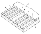
本発明を図1〜図11に示す一実施例によって以下に説明する。屋根パネル(1) は野地面材(2) と、該野地面材(2) の下面に接着剤によって接着されている断熱材(3) とからなる。該断熱材(3) はポリスチレン発泡体、ポリエチレン発泡体、ポリプロピレン発泡体、半硬質ポリウレタン発泡体、フェノール樹脂発泡体、メラミン樹脂発泡体等のプラスチック発泡体からなり、上面には複数条(本実施例では6条)の通気路(4) が形成されている。該通気路(4) の間隔は後述する垂木嵌合溝を形成する余地を考慮して中央部において広く設定しておく。
【0008】
該断熱材(3) は成形時に通気路(4) を一体的に形成するか、あるいは成形後に通気路(4) を切削加工等によって形成する。
【0009】
図2には野地面材(2) の下面に断熱材(3) を接着した構成が示されるが、該断熱材(3) を図2点線に沿って切除して図3に示すように垂木嵌合溝(5,5A)を形成する。なお両端の嵌合溝(5A)の巾は他の嵌合溝(5) の巾の1/2に設定する。
【0010】
このようにして図3に示す屋根パネル(1) が作成され、図4に示すように該屋根パネル(1) は屋根骨格の垂木(6) 上に被着され、該垂木(6) を該屋根パネル(1) の断熱材(3) の垂木嵌合溝(5,5A)に嵌合する。
【0011】
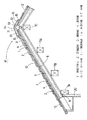
図5に示すように該垂木(6) は下側において軒桁(7A)、母屋(7B)、棟木(7C)によって支持されている。そして該屋根パネル(1) の横方向の相互接続部においては、該断熱材(3) と垂木(6) との間にシール材(8) を介在させて水密性を確保している。
【0012】
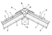
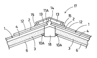
更に軒先部にあっては該屋根パネル(1) の断熱材(3) の通気路(4) 軒先側端は外気に開放されており、また該断熱材(3) の下面は壁断熱材(20)の上端と当接しており、該屋根パネル(1) の断熱材(3) の下面と該壁断熱材(20)の上端との間に形成されている隙間には軟質ポリウレタン発泡体、軟質ポリ塩化ビニル発泡体、合成ゴムスポンジ等の軟質プラスチック発泡体からなる断熱性シール材(9) を充填し、屋根の断熱材(3) と壁断熱材(20)との接合部において、断熱構造の連続性が断たれることを防止している。更に棟部にあっても左右の屋根パネル(1,1) の接合部の隙間にも、同様な断熱性シール材(10)が充填されて断熱構造の連続性が断たれることを防止しているが、該断熱性シール材(10)は該屋根パネル(1) の通気路(4) を閉塞しないようにし、棟に沿って左右の屋根パネル(1,1) 間に形成される横通気路(11)に該屋根パネル(1,1) の各通気路(4,4) の棟側端が開放されるように設定されている。
【0013】
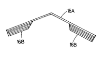
該屋根パネル(1) の野地面材(2) の上面には、屋根材(12)が葺設される。そして棟部にあっては笠木(13,13) を介して水切り板(14)が被覆されているが、該水切り板(14)と屋根材(12)との間にはシール材(15)が充填されている。そして棟部所定個所には図6に示すような棟換気部材(16)が被着されており、屋根(17)の該横通気路(11)が該棟換気部材(16)を介して外気に開放されるように設定されている。該棟換気部材(16)はポリプロピレン、ポリ塩化ビニル等のプラスチックを材料とし、笠形水切り板(16A) と、該水切り板(16A) の下面両側に接着される通気性ブロック(16B) とからなり、該通気性ブロック(16B) には例えばハニカム状に多数の連通孔が設けられている。
【0014】
上記屋根(17)にあっては、軒先側の換気は屋根パネル(1) の通気路(4) の軒先端が直接外気に開放していることによって行なわれ、棟側換気は屋根パネル(1) の通気路(4) が横通気路(11)に開放され、該横通気路(11)が該棟換気部材(16)を介して外気に開放されることによって行なわれる。
【0015】
屋根(17)には図8に示すように両端が内側に傾斜している寄棟部(17A) が形成される場合がある。この場合には図9に示すように寄棟部(17A) において左右の屋根パネル(1,1) の断熱材(3) の寄棟側端部を切欠き、その間に隅木(18)が嵌合された状態とする。この際左右の屋根パネル(1,1) の通気路(4,4) の下端と該隅木(18)の天端とを一致させ該通気路(4,4) が該隅木(18)によって閉塞されないようにし、かつ左右の屋根パネル(1,1) の野地面材(2,2) が間隙を介して相対するように設定し、寄棟部(17A) に形成される通気路(11A) を屋根(17)の横通気路(11)に開放する。なお隅木(18)とその両側の屋根パネル(1,1) の断熱材(3,3) の接触部下端は断熱性シール材(10A) によってシールして、断熱性を確保する。
【0016】
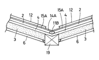
更に図10に示すように中央から直角に屋根(17B) が分岐した構造のものがある。この場合には屋根(17)と分岐屋根(17B) との間に本谷部(17C) が形成される。この場合においても図11に示すように屋根パネル(1,1) の断熱材(3,3) の本谷部側端部を切欠き、その間に谷木(19)が嵌合された状態とする。その際左右の屋根パネル(1,1) の通気路(4,4) の下端と該谷木(19)の天端とを一致させ、該通気路(4,4) が該谷木(19)によって閉塞されないようにし、かつ左右の屋根パネル(1,1) の野地面材(2,2) が間隙を介して相対するように設定し、本谷部(17C) に外気に開放する通気路(11B) を確保する。なお本谷部(17C) にあっては逆笠形の水切り板(14A) がシール材(15A) を介して被着されている。
【0017】
本実施例では断熱材の上面に通気路を形成したが、断熱材の中間に通気路を穿設してもよい。しかし断熱材上面に通気路を形成した方が加工が便利である。
更に垂木嵌合溝は断熱材を切除して設ける以外、断熱材を垂木嵌合溝分間隔をあけて野地面材に接着することによって設けてもよい。
【0018】
【発明の効果】
本発明においては、胴縁や野地面板をもう一枚必要とすることなく、少ない部材で効率良く屋根の換気を図ることが出来る。
【図面の簡単な説明】
図1〜図11は本発明の一実施例を示すものである。
【図1】断熱材および野地面材の部分斜視図
【図2】野地面材に断熱材を接着した状態の断面図
【図3】屋根パネルの横断面図
【図4】屋根パネルを屋根骨格上に被着した状態の部分横断面図
【図5】屋根パネルを屋根骨格上に被着した状態の部分縦断面図
【図6】棟部の横断面図
【図7】棟換気部材の正面図
【図8】寄棟部を有する屋根の説明図
【図9】図8におけるA−A断面図
【図10】本谷部を有する屋根の説明図
【図11】図9におけるB−B断面図
【図12】従来例の屋根パネルを屋根上に被着した状態の部分横断面図
【符号の説明】
1 屋根パネル
2 野地面材
3 断熱材
4 通気路
5,5A 垂木嵌合溝
6 垂木
8,9,10 シール材
17 屋根
18 隅木
19 谷木
20 壁断熱材[0001]
[Industrial applications]
TECHNICAL FIELD The present invention relates to a roof panel and a permeable roof base structure using the roof panel.
[0002]
[Prior art]
As a conventional air-permeable roof foundation structure, as shown in FIG. 12, a waist edge (24) is fixed at a predetermined interval on the upper surface of a lower ground surface material (22), and between the waist edges (24). A heat insulating material (23) is inserted, and a roof base panel (21) having its body edge (24) protruding from an upper surface of the heat insulating material (23) is fixed on a rafter (26). A structure is provided in which an upper ground material (25) is stretched above the torso rim (24).
[0003]
[Problems to be solved by the invention]
In the above-mentioned conventional air-permeable roof foundation structure, a gap (27) is provided between the heat insulating material (23) and the upper ground surface material (25) as a trunk edge (24) serving as a spacer, The gap (27) provides air permeability. However, since the ground material is required on the upper side and the lower side, and the rim is also necessary, there is a problem that the number of members is increased, the material cost is increased, and the construction is troublesome. . Also, there is a problem that the design of the building is inferior because the thickness of the roof is increased.
[0004]
[Means for Solving the Problems]
According to the present invention, as a means for solving the above-mentioned conventional problems, a plurality of heat insulating materials (3) made of a plastic foam having a plurality of air passages (4) penetrated on the lower surface of a ground surface material (2) are provided. The roof panel (1) bonded through the rafter fitting groove (5, 5A) and the roof panel (1) are mounted on a rafter (6) of a roof frame, and the rafter (6) is attached to the roof panel ( 1) is fitted into the rafter fitting groove (5, 5A) of the heat insulating material (3), and the ventilation path (4) of the heat insulating material (3) of the roof panel (1) is exposed to outside air between the eaves and the ridge. It provides an open, breathable roof base structure.
In the above-mentioned roof panel (1), it is desirable that the ventilation path (4) of the heat insulating material (3) is provided through the upper surface of the heat insulating material (3), and the rafter fitting grooves (5, 5A) are It is desirable that the heat insulating material (3) is provided by cutting the heat insulating material (3) from the lower surface and dividing the heat insulating material (3).
Further, in the above-described air-permeable roof base structure, at least at a connection portion between the roof panels (1, 1), the heat insulating material (3, 3) of the roof panels (1, 1) and the rafters (6) are connected. It is desirable that a sealing material (8) is interposed on the joint surface, and the lower surface of the heat insulating material (3) of the roof panel (1) attached on the rafter (6) is a wall heat insulating material ( The gap formed between the lower surface of the heat insulating material (3) of the roof panel (1) and the upper end of the wall heat insulating material (20) is filled with a sealing material (9). In the ridge section, the air gaps (4, 4) of the heat insulating material (3, 3) of the roof panels (1, 1) should not be blocked in the gaps between the left and right roof panels (1, 1). It is desirable to fill the sealing material (10) with the sealing material. The sealing material (10) is desirably a heat-insulating sealing material made of a soft plastic foam. If there is a ridge (17A) or a valley (17C) on the roof (17) to be constructed, cut off the insulation (3, 3) on the left and right roof panels (1, 1) at this part. In addition, the edges of the ground material (2) of the left and right roof panels (1, 1) are opposed to each other with a gap provided therebetween, and the cut-off portions of the heat insulating material (3, 3) of the roof panels (1, 1) are further provided. A corner (18) or a valley (19) interposed between the right and left rafters (6, 6) is fitted, and the top of the corner (18) or the valley (19) is attached to the roof panel (1, 1). It is desirable to match the lower end of the ventilation path (4, 4) of the heat insulating material (3, 3).
[0005]
[Action]
In the permeable roof base structure using the roof panel (1), a ventilation path (4) is provided in the heat insulating material (3), and the ventilation path (4) is connected to the outside air at the eaves and the ridge. Because the roof is open to the outside, the roof can be ventilated without increasing the thickness of the roof.
[0006]
At least at the joint between the roof panels (1, 1), a sealing material (8) is provided on the joint surface between the heat insulating material (3, 3) and the rafters (6, 6) of the roof panel (1, 1). If interposed, the watertightness of the roof foundation structure is ensured. Further, the lower surface of the heat insulating material (3) of the roof panel (1) attached on the rafter (6) is brought into contact with the upper end of the wall heat insulating material (20) at the eaves tip, and the heat insulating material of the roof panel (1) is formed. The gap formed between the lower surface of (3) and the upper end of the wall heat insulating material (20) is filled with a sealing material (9), and the gap between the left and right roof panels (1, 1) in the ridge portion. When the sealing material (10) is filled so as not to block the ventilation path (4, 4) of the heat insulating material (3, 3) of the roof panel (1, 1), the watertightness of the roof foundation structure is secured. However, if the sealing material (10) is a heat-insulating sealing material made of a soft plastic foam, a roof base structure having a continuous heat-insulating structure is obtained, and the heat insulation of the roof (17) is improved. If the roof to be constructed (17) has a ridge (17A) or a valley (17C), the insulation of the left and right roof panels is cut off at this portion, and the left and right roof panels (1,1) are cut off. The edges of the ground material (2) of the roof panel (1, 1) are opposed to each other with a gap therebetween, and the cut-off portion of the thermal insulation (3, 3) of the roof panel (1, 1) is interposed between the left and right rafters (6, 6). The corners (18) or valleys (19) to be fitted are fitted, and the tops of the corners (18) or valleys (19) are connected to the air passages of the heat insulating material (3, 3) of the roof panel (1, 1). (4, 4) Align with the lower end to ensure heat insulation and air permeability.
[0007]
BEST MODE FOR CARRYING OUT THE INVENTION
The present invention will be described below with reference to an embodiment shown in FIGS. The roof panel (1) comprises a ground material (2) and a heat insulating material (3) bonded to the lower surface of the ground material (2) by an adhesive. The heat insulating material (3) is made of plastic foam such as polystyrene foam, polyethylene foam, polypropylene foam, semi-rigid polyurethane foam, phenol resin foam, melamine resin foam, etc. In the example, six passages (4) are formed. The interval of the ventilation path (4) is set wide at the center in consideration of the room for forming the rafter fitting groove described later.
[0008]
In the heat insulating material (3), the air passage (4) is integrally formed at the time of molding, or the air passage (4) is formed by cutting or the like after the molding.
[0009]
FIG. 2 shows a configuration in which a heat insulating material (3) is adhered to the lower surface of the ground material (2). The heat insulating material (3) is cut along the dotted line in FIG. A fitting groove (5, 5A) is formed. Note that the width of the fitting groove (5A) at both ends is set to 1 / of the width of the other fitting groove (5).
[0010]
In this way, the roof panel (1) shown in FIG. 3 is prepared, and as shown in FIG. 4, the roof panel (1) is mounted on the roof frame rafter (6). Fit into the rafter fitting groove (5, 5A) of the heat insulating material (3) of the roof panel (1).
[0011]
As shown in FIG. 5, the rafter (6) is supported on the lower side by an eaves girder (7A), a purlin (7B), and a purlin (7C). At the horizontal interconnection of the roof panel (1), a sealing material (8) is interposed between the heat insulating material (3) and the rafter (6) to ensure watertightness.
[0012]
Further, in the eaves front part, the ventilation path (4) of the heat insulating material (3) of the roof panel (1) is open to the outside air, and the lower surface of the heat insulating material (3) is a wall heat insulating material (3). 20), a gap formed between the lower surface of the heat insulating material (3) of the roof panel (1) and the upper end of the wall heat insulating material (20); A heat-insulating sealing material (9) made of a soft plastic foam such as a soft polyvinyl chloride foam or a synthetic rubber sponge is filled, and a heat insulating material is provided at the joint between the roof heat insulating material (3) and the wall heat insulating material (20). This prevents the continuity of the structure from being interrupted. Further, even in the ridge, the gap between the joints of the left and right roof panels (1, 1) is filled with a similar heat insulating seal material (10) to prevent the continuity of the heat insulating structure from being interrupted. However, the heat insulating sealing material (10) does not block the ventilation path (4) of the roof panel (1), and the side formed between the left and right roof panels (1,1) along the ridge. The ridge side end of each ventilation path (4, 4) of the roof panel (1, 1) is set to be open to the ventilation path (11).
[0013]
A roofing material (12) is laid on the roof panel (1) on the upper surface of the ground material (2). In the ridge part, a draining board (14) is covered via a cap (13, 13), and a sealing material (15) is provided between the draining board (14) and the roofing material (12). Is filled. A ridge ventilation member (16) as shown in FIG. 6 is attached to a predetermined portion of the ridge, and the lateral ventilation path (11) of the roof (17) is connected to the outside air through the ridge ventilation member (16). It is set to be open to the public. The ridge ventilation member (16) is made of a plastic such as polypropylene or polyvinyl chloride, and comprises a hat-shaped drainer (16A) and a permeable block (16B) bonded to both lower surfaces of the drainer (16A). The air-permeable block (16B) is provided with a large number of communication holes in a honeycomb shape, for example.
[0014]
In the above-mentioned roof (17), ventilation at the eaves side is performed by the eaves end of the ventilation path (4) of the roof panel (1) being directly open to the outside air. The ventilation path (4) is opened to the lateral ventilation path (11), and the lateral ventilation path (11) is opened to the outside air through the ridge ventilation member (16).
[0015]
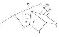
As shown in FIG. 8, the roof (17) may have a ridge (17A) having both ends inclined inward. In this case, as shown in FIG. 9, at the ridge part (17A), the ridge side ends of the heat insulating material (3) of the left and right roof panels (1, 1) are cut out, and a corner block (18) is fitted therebetween. It will be in the state of being merged. At this time, the lower ends of the ventilation paths (4, 4) of the left and right roof panels (1, 1) and the top end of the corner block (18) are made to coincide with each other, and the ventilation path (4, 4) is closed by the corner block (18). The air passage (11A) formed in the ridge part (17A) is set so that the ground materials (2, 2) of the left and right roof panels (1, 1) are opposed to each other via a gap. Is opened to the lateral ventilation path (11) of the roof (17). The lower end of the contact between the corner block (18) and the heat insulating material (3, 3) of the roof panel (1, 1) on both sides is sealed with a heat insulating seal material (10A) to secure heat insulation.
[0016]
Further, as shown in FIG. 10, there is a structure in which a roof (17B) branches at a right angle from the center. In this case, a valley (17C) is formed between the roof (17) and the branch roof (17B). Also in this case, as shown in FIG. 11, the heat insulating material (3, 3) of the roof panel (1, 1) is cut off at the main valley side end, and a valley (19) is fitted between the cut ends. . At this time, the lower ends of the air passages (4, 4) of the left and right roof panels (1, 1) and the top end of the valley (19) are made to coincide with each other, and the air passage (4, 4) is ), And the ground material (2, 2) of the left and right roof panels (1, 1) is set so as to be opposed to each other through a gap, and the air passage is opened to the outside at the valley (17C). (11B) is secured. In the main valley (17C), an inverted cap-shaped drainer (14A) is attached via a sealing material (15A).
[0017]
In this embodiment, the ventilation path is formed on the upper surface of the heat insulating material. However, a ventilation path may be formed in the middle of the heat insulating material. However, it is more convenient to form a ventilation path on the upper surface of the heat insulating material.
Further, instead of providing the rafter fitting groove by cutting off the heat insulating material, the rafter fitting groove may be provided by bonding the heat insulating material to the ground material at intervals of the rafter fitting groove.
[0018]
【The invention's effect】
In the present invention, it is possible to efficiently ventilate the roof with a small number of members without requiring another rim or a ground plane.
[Brief description of the drawings]
1 to 11 show one embodiment of the present invention.
FIG. 1 is a partial perspective view of a heat insulating material and a ground material. FIG. 2 is a cross-sectional view of a state where a heat insulating material is bonded to the ground material. FIG. 3 is a cross-sectional view of a roof panel. FIG. FIG. 5 is a partial longitudinal sectional view showing a roof panel attached to a roof frame. FIG. 6 is a transverse sectional view of a ridge part. FIG. 7 is a front view of a ridge ventilation member. FIG. 8 is an explanatory view of a roof having a ridge section. FIG. 9 is an AA sectional view of FIG. 8. FIG. 10 is an explanatory view of a roof having a valley section. FIG. 11 is a BB sectional view of FIG. FIG. 12 is a partial cross-sectional view of a state in which a conventional roof panel is attached on a roof.
DESCRIPTION OF
Claims (8)
Priority Applications (1)
| Application Number | Priority Date | Filing Date | Title |
|---|---|---|---|
| JP2002282793A JP3657935B2 (en) | 2002-09-27 | 2002-09-27 | Breathable roof base structure |
Applications Claiming Priority (1)
| Application Number | Priority Date | Filing Date | Title |
|---|---|---|---|
| JP2002282793A JP3657935B2 (en) | 2002-09-27 | 2002-09-27 | Breathable roof base structure |
Publications (2)
| Publication Number | Publication Date |
|---|---|
| JP2004116191A true JP2004116191A (en) | 2004-04-15 |
| JP3657935B2 JP3657935B2 (en) | 2005-06-08 |
Family
ID=32276851
Family Applications (1)
| Application Number | Title | Priority Date | Filing Date |
|---|---|---|---|
| JP2002282793A Expired - Lifetime JP3657935B2 (en) | 2002-09-27 | 2002-09-27 | Breathable roof base structure |
Country Status (1)
| Country | Link |
|---|---|
| JP (1) | JP3657935B2 (en) |
Cited By (3)
| Publication number | Priority date | Publication date | Assignee | Title |
|---|---|---|---|---|
| JP2008202270A (en) * | 2007-02-19 | 2008-09-04 | Kikkona Kk | Roof panel and venting roof underlayer structure |
| JP2009024386A (en) * | 2007-07-19 | 2009-02-05 | Tesuku:Kk | Structure of wooden external heat insulation roof |
| JP2010084481A (en) * | 2008-10-02 | 2010-04-15 | Tesuku:Kk | Ventilation heat-insulating roof composite panel, and wooden external heat-insulating roof structure using the panel |
-
2002
- 2002-09-27 JP JP2002282793A patent/JP3657935B2/en not_active Expired - Lifetime
Cited By (4)
| Publication number | Priority date | Publication date | Assignee | Title |
|---|---|---|---|---|
| JP2008202270A (en) * | 2007-02-19 | 2008-09-04 | Kikkona Kk | Roof panel and venting roof underlayer structure |
| JP2009024386A (en) * | 2007-07-19 | 2009-02-05 | Tesuku:Kk | Structure of wooden external heat insulation roof |
| JP4743639B2 (en) * | 2007-07-19 | 2011-08-10 | 株式会社テスク | Wooden exterior insulation roof structure |
| JP2010084481A (en) * | 2008-10-02 | 2010-04-15 | Tesuku:Kk | Ventilation heat-insulating roof composite panel, and wooden external heat-insulating roof structure using the panel |
Also Published As
| Publication number | Publication date |
|---|---|
| JP3657935B2 (en) | 2005-06-08 |
Similar Documents
| Publication | Publication Date | Title |
|---|---|---|
| JPH1037321A (en) | Draining and venting structure work execution method for building overhang part | |
| JP4028881B2 (en) | Roof panel and breathable roof structure | |
| JP2004116191A (en) | Roof panel and venting roof bed structure | |
| JP2010121378A (en) | Roof panel, venting roof-underlayer structure, and venting structure of hipped roof and branched roof | |
| JP2006233594A (en) | Roof panel and roof heat insulating structure | |
| JPH10205015A (en) | Building equipped with ventilative layer | |
| JP2009161960A (en) | Venting structure of hipped and branched roof | |
| JP2010090539A (en) | Roof panel and roof structure | |
| JP2008202270A (en) | Roof panel and venting roof underlayer structure | |
| JP3912590B2 (en) | Insulated airtight structure | |
| JP3147145U (en) | Roof panel and roof structure | |
| JP2010031632A (en) | Roof panel and ventilating roof substrate structure using the same | |
| JP4124916B2 (en) | Exterior wall structure and method of attaching sash frame to exterior wall | |
| JP3873227B2 (en) | Thermal insulation panel | |
| JPH1181506A (en) | Venting layer forming body and mounting structure thereof, and wall | |
| JPH08291600A (en) | Ventilating roof panel | |
| JP3809256B2 (en) | Ventilation building structure of the dormitory roof | |
| JPH10183793A (en) | Building having aeration layer | |
| JP7187232B2 (en) | Waterproof structure of eaves | |
| JPH10140691A (en) | Structural panel | |
| JP2503698Y2 (en) | Roof equipment | |
| JP2001020417A (en) | Exterior wall construction | |
| JPH0722424Y2 (en) | Roofing equipment | |
| JPH0376375B2 (en) | ||
| JPH0978781A (en) | Ventilation ridge structure |
Legal Events
| Date | Code | Title | Description |
|---|---|---|---|
| A131 | Notification of reasons for refusal |
Free format text: JAPANESE INTERMEDIATE CODE: A131 Effective date: 20040824 |
|
| A521 | Request for written amendment filed |
Free format text: JAPANESE INTERMEDIATE CODE: A523 Effective date: 20041018 |
|
| TRDD | Decision of grant or rejection written | ||
| A01 | Written decision to grant a patent or to grant a registration (utility model) |
Free format text: JAPANESE INTERMEDIATE CODE: A01 Effective date: 20050301 |
|
| A61 | First payment of annual fees (during grant procedure) |
Free format text: JAPANESE INTERMEDIATE CODE: A61 Effective date: 20050310 |
|
| R150 | Certificate of patent or registration of utility model |
Ref document number: 3657935 Country of ref document: JP Free format text: JAPANESE INTERMEDIATE CODE: R150 Free format text: JAPANESE INTERMEDIATE CODE: R150 |
|
| FPAY | Renewal fee payment (event date is renewal date of database) |
Free format text: PAYMENT UNTIL: 20080318 Year of fee payment: 3 |
|
| FPAY | Renewal fee payment (event date is renewal date of database) |
Free format text: PAYMENT UNTIL: 20110318 Year of fee payment: 6 |
|
| R250 | Receipt of annual fees |
Free format text: JAPANESE INTERMEDIATE CODE: R250 |
|
| S111 | Request for change of ownership or part of ownership |
Free format text: JAPANESE INTERMEDIATE CODE: R313115 |
|
| FPAY | Renewal fee payment (event date is renewal date of database) |
Free format text: PAYMENT UNTIL: 20110318 Year of fee payment: 6 |
|
| R350 | Written notification of registration of transfer |
Free format text: JAPANESE INTERMEDIATE CODE: R350 |
|
| FPAY | Renewal fee payment (event date is renewal date of database) |
Free format text: PAYMENT UNTIL: 20110318 Year of fee payment: 6 |
|
| FPAY | Renewal fee payment (event date is renewal date of database) |
Free format text: PAYMENT UNTIL: 20140318 Year of fee payment: 9 |
|
| R250 | Receipt of annual fees |
Free format text: JAPANESE INTERMEDIATE CODE: R250 |
|
| R250 | Receipt of annual fees |
Free format text: JAPANESE INTERMEDIATE CODE: R250 |
|
| R250 | Receipt of annual fees |
Free format text: JAPANESE INTERMEDIATE CODE: R250 |
|
| R250 | Receipt of annual fees |
Free format text: JAPANESE INTERMEDIATE CODE: R250 |
|
| EXPY | Cancellation because of completion of term |