JP2006233594A - Roof panel and roof heat insulating structure - Google Patents

Roof panel and roof heat insulating structure Download PDF

Info

Publication number
JP2006233594A
JP2006233594A JP2005050149A JP2005050149A JP2006233594A JP 2006233594 A JP2006233594 A JP 2006233594A JP 2005050149 A JP2005050149 A JP 2005050149A JP 2005050149 A JP2005050149 A JP 2005050149A JP 2006233594 A JP2006233594 A JP 2006233594A
Authority
JP
Japan
Prior art keywords
heat insulating
roof
insulating material
roof panel
rafter
Prior art date
Legal status (The legal status is an assumption and is not a legal conclusion. Google has not performed a legal analysis and makes no representation as to the accuracy of the status listed.)
Pending
Application number
JP2005050149A
Other languages
Japanese (ja)
Inventor
Shigekiyo Tsuge
茂清 柘植
Hiroshi Hiyoudo
博 兵道
Current Assignee (The listed assignees may be inaccurate. Google has not performed a legal analysis and makes no representation or warranty as to the accuracy of the list.)
KIKKONA KK
SALA JUTAKU KK
Original Assignee
KIKKONA KK
SALA JUTAKU KK
Priority date (The priority date is an assumption and is not a legal conclusion. Google has not performed a legal analysis and makes no representation as to the accuracy of the date listed.)
Filing date
Publication date
Application filed by KIKKONA KK, SALA JUTAKU KK filed Critical KIKKONA KK
Priority to JP2005050149A priority Critical patent/JP2006233594A/en
Publication of JP2006233594A publication Critical patent/JP2006233594A/en
Pending legal-status Critical Current

Links

Images

Landscapes

  • Building Environments (AREA)

Abstract

<P>PROBLEM TO BE SOLVED: To provide a roof panel and a roof heat insulating structure high in air permeability and heat insulating property. <P>SOLUTION: The roof panel 1 is formed by bonding a plurality of heat insulating materials 3 formed of plastic foams penetrating a plurality of vent passages 4 and rafter fitting grooves 5, 5a provided through, to the lower face of a sheathing face material 2 to make the heat insulating materials 3 continuous. The roof heat insulting structure is provided by mounting the roof panel 1 on rafters 6 of a roof skeleton, fitting the rafters 6 into the rafter fitting grooves 5, 5a of the heat insulating materials 3 of the roof panel 1, opening the vent passages 4 of the heat insulating materials 3 to the outside air at the eaves and a ridge part, and making the heat insulating materials 3 continuous at the mutual connection parts of the roof panels 1. <P>COPYRIGHT: (C)2006,JPO&NCIPI

Description

本発明は屋根パネルおよび該屋根パネルを使用した屋根断熱構造に関する。   The present invention relates to a roof panel and a roof insulation structure using the roof panel.

従来、通気性の高い屋根構造として、野地面材の下面に複数条の通気路を貫設したプラスチック発泡体からなる断熱材の複数枚を垂木嵌合溝を介して接着した屋根パネルを、屋根骨格の垂木上に被着し、該垂木を該屋根パネルの断熱材の垂木嵌合溝に嵌合し、軒先と棟部において該屋根パネルの断熱材の通気路を外気に開放した通気性屋根下地構造が一般に提供されている(特許文献1参照)。   Conventionally, as a highly breathable roof structure, a roof panel in which a plurality of insulation materials made of a plastic foam having a plurality of air passages provided on the lower surface of a field ground material are bonded via a rafter fitting groove, A breathable roof which is deposited on a rafter of a skeleton, and the rafter is fitted into a rafter fitting groove of a heat insulating material of the roof panel, and a ventilation passage of the heat insulating material of the roof panel is opened to the outside at the eaves and the ridge. A base structure is generally provided (see Patent Document 1).

特開2004−116191号公報(第3−5頁、第5図)JP 2004-116191 A (page 3-5, FIG. 5)

しかしながら上記従来の構成では、屋根構造の通気性は非常に高いものの、屋根パネルの断熱材が不連続であるため、屋根構造の断熱性が若干低下してしまうという問題があった。   However, in the above conventional configuration, although the air permeability of the roof structure is very high, there is a problem that the heat insulating property of the roof structure is slightly lowered because the heat insulating material of the roof panel is discontinuous.

本発明は上記従来の課題を解決するための手段として、野地面材2の下面に複数条の通気路4と垂木嵌合溝5,5aを貫設したプラスチック発泡体からなる断熱材3の複数枚を接着し、該断熱材3を連続させた屋根パネル1を提供するものである。
該通気路4は該断熱材3の上面に貫設され、該垂木嵌合溝5,5aは該断熱材3の下面に貫設されることが望ましい。
また本発明では、上記の屋根パネル1を屋根骨格の垂木6上に被着し、該垂木6を該屋根パネル1の断熱材3の垂木嵌合溝5,5aに嵌合し、軒先と棟部とにおいて該断熱材3の通気路4を外気に開放するとともに、該屋根パネル1相互の接続部において該断熱材3を連続させた屋根断熱構造が提供される。
そして、構築される屋根19に寄棟部19Aまたは本谷部19Bが存在する場合、この部分で左右の屋根パネル1の断熱材3をそれぞれ切除し、該左右の屋根パネル1の断熱材3を断熱部材20A,20Bを介して連続させるとともに、該断熱部材20A,20Bの下面を左右の垂木6間に介在する隅木21または谷木24の上面に当接させ、更に、該断熱材3の通気路4と断熱部材20A,20Bの通気路23A,23Bとを連通させたことが望ましい。
また、少なくとも該屋根パネル1相互の接続部において、該屋根パネル1の断熱材3と垂木6との接合面にはシール材7が介在していることが望ましい。
更に、該垂木6上に被着された屋根パネル1の断熱材3の下面は軒先部において壁断熱材9の上端に当接させ、該断熱材3の下面と該壁断熱材9の上端との間に形成される隙間にはシール材10aを充填し、棟部にあっては左右の屋根パネル1の隙間には該屋根パネル1の断熱材3の通気路4を閉塞しないようにして10bを充填したことが望ましい。
また更に、該シール材10a,10bは軟質プラスチック発泡体からなる断熱性シール材であることが望ましい。
As a means for solving the above-described conventional problems, the present invention provides a plurality of heat insulating materials 3 made of plastic foam in which a plurality of air passages 4 and rafter fitting grooves 5 and 5a are provided on the lower surface of the field material 2. The roof panel 1 which bonded the sheet | seat and made this heat insulating material 3 continuous is provided.
It is desirable that the ventilation path 4 penetrates the upper surface of the heat insulating material 3, and the rafter fitting grooves 5 and 5 a penetrate the lower surface of the heat insulating material 3.
In the present invention, the roof panel 1 is attached onto the rafter 6 of the roof skeleton, the rafter 6 is fitted into the rafter fitting grooves 5 and 5a of the heat insulating material 3 of the roof panel 1, And a heat insulating structure in which the heat insulating material 3 is made continuous at the connecting portion between the roof panels 1.
And when the building 19A or the main valley part 19B exists in the constructed | assembled roof 19, the heat insulating material 3 of the left and right roof panels 1 is cut off in this part, respectively, and the heat insulating material 3 of the left and right roof panels 1 is insulated. The heat insulating members 20A and 20B are made continuous through the members 20A and 20B, the lower surfaces of the heat insulating members 20A and 20B are brought into contact with the upper surfaces of the corners 21 or the valleys 24 interposed between the left and right rafters 6, and the air passages of the heat insulating material 3 4 and the air passages 23A and 23B of the heat insulating members 20A and 20B are preferably communicated with each other.
Moreover, it is desirable that a sealing material 7 be interposed at the joint surface between the heat insulating material 3 and the rafter 6 of the roof panel 1 at least in the connection portion between the roof panels 1.
Further, the lower surface of the heat insulating material 3 of the roof panel 1 deposited on the rafter 6 is brought into contact with the upper end of the wall heat insulating material 9 at the eaves portion, and the lower surface of the heat insulating material 3 and the upper end of the wall heat insulating material 9 are In the ridge, the gap between the left and right roof panels 1 is filled with the sealing material 10a so that the air passage 4 of the heat insulating material 3 of the roof panel 1 is not blocked. It is desirable to fill.
Furthermore, the sealing materials 10a and 10b are preferably heat insulating sealing materials made of a soft plastic foam.

本発明の屋根パネル1を使用した屋根断熱構造では、屋根パネル1の断熱材3が連続しており、断熱材3が不連続となる箇所がないため、屋根構造の断熱性が大幅に向上する。その上、該断熱材3には通気路4が設けられており、該通気路4が軒先と棟部において外気に開放されているので、屋根19の厚さを厚くすることなく屋根19の通気性が確保される。   In the roof heat insulating structure using the roof panel 1 of the present invention, since the heat insulating material 3 of the roof panel 1 is continuous and there is no portion where the heat insulating material 3 is discontinuous, the heat insulating property of the roof structure is greatly improved. . In addition, the heat insulating material 3 is provided with a ventilation path 4, and the ventilation path 4 is open to the outside air at the eaves and the ridge, so that the ventilation of the roof 19 can be performed without increasing the thickness of the roof 19. Sex is secured.

本発明を図1〜図15に示す一実施例によって説明する。
図1および図2に示すように、屋根パネル1は、野地面材2と、該野地面材2の下面に接着剤によって接着されている断熱材3とからなる。本実施例では、該断熱材3の材料として、ポリスチレン発泡体、ポリエチレン発泡体、ポリプロピレン発泡体、半硬質ポリウレタン発泡体、フェノール樹脂発泡体、メラミン樹脂発泡体等のプラスチック発泡体が用いられている。
The present invention will be described with reference to an embodiment shown in FIGS.
As shown in FIGS. 1 and 2, the roof panel 1 includes a field material 2 and a heat insulating material 3 bonded to the lower surface of the field material 2 with an adhesive. In this embodiment, plastic foams such as polystyrene foam, polyethylene foam, polypropylene foam, semi-rigid polyurethane foam, phenol resin foam, and melamine resin foam are used as the material of the heat insulating material 3. .

該断熱材3の上面には6条の通気路4が貫設されており、該断熱材3の下面には中央部および両端部において垂木嵌合溝5,5aが貫設されている。ここで、該両端部の垂木嵌合溝5aの幅は、該中央部の垂木嵌合溝5の幅の1/2に設定されている。また、該通気路4の間隔は、該中央部の垂木嵌合溝5を形成する余地を考慮して、中央部において広く設定されている。
なお、該断熱材3の通気路4と垂木嵌合溝5,5aは、該断熱材3の成形時に一体的に形成してもよく、該断熱材3の成形後に切削加工等によって形成してもよい。
Six air passages 4 are provided through the upper surface of the heat insulating material 3, and rafter fitting grooves 5 and 5 a are provided through the lower surface of the heat insulating material 3 at the center and both ends. Here, the width of the rafter fitting groove 5a at both ends is set to ½ of the width of the rafter fitting groove 5 at the center. Moreover, the space | interval of this ventilation path 4 is set widely in the center part in consideration of the room which forms the rafter fitting groove | channel 5 of this center part.
The air passage 4 and the rafter fitting grooves 5 and 5a of the heat insulating material 3 may be formed integrally when the heat insulating material 3 is formed, or formed by cutting or the like after the heat insulating material 3 is formed. Also good.

このようにして、図2に示す屋根パネル1が作成されるが、それ以外、屋根パネル1は、図3に示すように、上記の断熱材3を中央で半分に切断した形状の分割断熱材3aを二つ使用して、野地面材2の下面において二つの分割断熱材3aを相互に接合して作成してもよい。   In this way, the roof panel 1 shown in FIG. 2 is created. Other than that, the roof panel 1 is a divided heat insulating material having a shape obtained by cutting the heat insulating material 3 in half at the center as shown in FIG. Two split heat insulating materials 3a may be joined to each other on the lower surface of the field material 2 using two 3a.

そして、図4に示すように、該屋根パネル1を屋根骨格の垂木6上に被着して、該垂木6を屋根パネル1の断熱材3の垂木嵌合溝5に嵌合する。このとき、該屋根パネル1の横方向の相互接続部においては、該断熱材3を連続させて断熱構造の連続性が断たれるのを防止するとともに、該断熱材3と該垂木6との間にシール材7を介在させて水密性を確保している。   Then, as shown in FIG. 4, the roof panel 1 is attached onto the rafter 6 of the roof skeleton, and the rafter 6 is fitted into the rafter fitting groove 5 of the heat insulating material 3 of the roof panel 1. At this time, in the lateral interconnection portion of the roof panel 1, the heat insulating material 3 is made continuous to prevent the continuity of the heat insulating structure from being interrupted, and between the heat insulating material 3 and the rafter 6. Sealing material 7 is interposed therebetween to ensure water tightness.

図5に示すように、該垂木6は下側において軒桁8a、母屋8b、棟木8cによって支持されている。そして、軒先部においては、該屋根パネル1の断熱材3の通気路4の軒先側端は、外気に開放されている。
また、該断熱材3の下面は壁断熱材9の上端と当接しており、該屋根パネル1の断熱材3の下面と該壁断熱材9の上端との間に形成されている隙間には、軟質ポリウレタン発泡体、軟質ポリ塩化ビニル発泡体、合成ゴムスポンジ等の軟質プラスチック発泡体からなる断熱性シール材10aが充填されている。こうして、屋根パネル1の断熱材3と壁断熱材9との接合部において、断熱構造の連続性が断たれるのを防止している。
更に、棟部においても、左右の屋根パネル1の接合部の隙間には、上記と同様の断熱性シール材10bが充填されており、断熱構造の連続性が断たれるのを防止している。しかし、この場合には、該断熱性シール材10a,10bは該屋根パネル1の通気路4を閉塞しないようにされており、棟に沿って左右の屋根パネル1の間に形成される横通気路11に、該屋根パネル1の各通気路4の棟側端が開放されるようにされている。
As shown in FIG. 5, the rafter 6 is supported on the lower side by an eaves girder 8a, a purlin 8b, and a purlin 8c. And in the eaves part, the eaves side end of the ventilation path 4 of the heat insulating material 3 of the roof panel 1 is open to the outside air.
Further, the lower surface of the heat insulating material 3 is in contact with the upper end of the wall heat insulating material 9, and there is a gap formed between the lower surface of the heat insulating material 3 of the roof panel 1 and the upper end of the wall heat insulating material 9. Insulating sealing material 10a made of soft plastic foam such as soft polyurethane foam, soft polyvinyl chloride foam, and synthetic rubber sponge is filled. Thus, the continuity of the heat insulating structure is prevented from being cut off at the joint between the heat insulating material 3 and the wall heat insulating material 9 of the roof panel 1.
Furthermore, also in the ridge, the gap between the joint portions of the left and right roof panels 1 is filled with the same heat insulating sealing material 10b as described above, thereby preventing the continuity of the heat insulating structure from being interrupted. . However, in this case, the heat insulating sealing materials 10a and 10b do not block the ventilation path 4 of the roof panel 1, and the horizontal ventilation formed between the left and right roof panels 1 along the ridge. A ridge side end of each ventilation path 4 of the roof panel 1 is opened to the path 11.

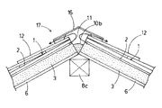
該屋根パネル1の野地面材2の上面には、屋根材12が葺設されている。そして、棟部においては、笠木13を介して水切り板14が被覆されており、該水切り板14と屋根材12との間にはシール材15が充填されている。図6に示すように、棟部の所定箇所には、棟換気部材16が被着されており、屋根19の横通気路11が該棟換気部材16を介して外気に開放されるようにされている。
図7に示すように、該棟換気部材16は、笠形の水切り板17と、該水切り板17の下面両側に接着される通気性ブロック18とからなり、該通気性ブロック18には、例えばハニカム状に多数の連通孔が設けられている。なお、本実施例では、該棟換気部材16の材料として、ポリプロピレン、ポリ塩化ビニル等のプラスチックが使用されている。
A roof material 12 is provided on the upper surface of the field ground material 2 of the roof panel 1. And in the ridge part, the draining board 14 is coat | covered via the headboard 13, The sealing material 15 is filled between this draining board 14 and the roofing material 12. As shown in FIG. As shown in FIG. 6, a ridge ventilation member 16 is attached to a predetermined portion of the ridge, and the lateral ventilation path 11 of the roof 19 is opened to the outside air via the ridge ventilation member 16. ing.
As shown in FIG. 7, the ridge ventilation member 16 includes a shade-shaped draining plate 17 and a breathable block 18 bonded to both sides of the lower surface of the draining plate 17. The breathable block 18 includes, for example, a honeycomb. A number of communication holes are provided in the shape. In the present embodiment, plastic such as polypropylene and polyvinyl chloride is used as the material of the building ventilation member 16.

上記の屋根19においては、軒先側の換気は、屋根パネル1の通気路4の軒先側端が直接外気に開放していることによって行われ、一方、棟側の換気は、屋根パネル1の通気路4が横通気路11に開放され、該横通気路11が該棟換気部材16を介して外気に開放されることによって行われる。   In the roof 19, the eaves side ventilation is performed by opening the eaves side end of the ventilation path 4 of the roof panel 1 directly to the outside air, while the ventilation on the ridge side is performed by the ventilation of the roof panel 1. The passage 4 is opened to the lateral ventilation path 11, and the lateral ventilation path 11 is opened to the outside air through the building ventilation member 16.

ところで、屋根19には、図8に示すように、両端が内側に傾斜している寄棟部19Aが形成されている場合がある。この場合には、図9に示す寄棟部用の断熱部材20Aを使用する。
図9に示すように、該寄棟部用の断熱部材20Aの下面の形状は、隅木21の上面の形状に沿った形状とされており、該断熱部材20Aの下面は該隅木21の上面に全面的に当接するようにされている。また、該寄棟部用の断熱部材20Aの上面には、野地面材2の端部を支持するための三個の支持ブロック22Aが突設されているとともに、図10において矢印で示すように屋根パネル1の断熱材3の通気路4と連通する通気路23Aが設けられている。
By the way, as shown in FIG. 8, the roof 19 may be formed with a berth 19A whose both ends are inclined inward. In this case, the heat insulating member 20A for the dormitory shown in FIG. 9 is used.
As shown in FIG. 9, the shape of the lower surface of the heat insulating member 20 </ b> A for the dormitory portion is formed along the shape of the upper surface of the corner tree 21, and the lower surface of the heat insulating member 20 </ b> A is formed on the upper surface of the corner tree 21. The entire surface is in contact. Further, on the upper surface of the heat insulating member 20A for the dormitory portion, three support blocks 22A for supporting the end of the field material 2 are projected, and as shown by arrows in FIG. An air passage 23A communicating with the air passage 4 of the heat insulating material 3 of the roof panel 1 is provided.

そして、寄棟部19Aの屋根構造を構築する場合には、図10および図11に示すように、寄棟部19Aにおいて左右の屋根パネル1の断熱材3の寄棟側端部を切除し、その間に該寄棟部用の断熱部材20Aを載置した隅木21が嵌合された状態とする。
このとき、該左右の屋根パネル1の断熱材3の寄棟側端部は該断熱部材20Aの両側面にそれぞれ当接し、該左右の屋根パネル1の断熱材3が該寄棟部用の断熱部材20Aを介して連続した状態となる。
また、屋根パネル1の断熱材3の通気路4の下端位置と寄棟部用の断熱部材20Aの通気路23Aの下端位置とは一致しており、該断熱材3の通気路4と該断熱部材20Aの通気路23Aとが連通された状態となって、図10において矢印で示すように屋根19の通気性が確保されている。
更に、寄棟部19Aにおいては、左右の屋根パネル1の野地面材2が間隙を介して相対するようにされており、寄棟部19Aに形成される通気路11Aは屋根19の横通気路11に開放されている。
なお、隅木21とその両側の屋根パネル1の断熱材3の接触部下端は断熱性シール材10Aによってシールして、断熱性が確保されている。また、寄棟部19Aにおいては、笠形の水切り板14Aがシール材15Aを介して被着されている。
And when constructing the roof structure of the berth part 19A, as shown in FIG. 10 and FIG. 11, the berth side edge part of the heat insulating material 3 of the right and left roof panels 1 is excised in the berth part 19A. In the meantime, the corner wood 21 on which the heat insulating member 20A for the dormitory portion is placed is fitted.
At this time, the dormitory side end portions of the heat insulating material 3 of the left and right roof panels 1 are in contact with both side surfaces of the heat insulating member 20A, respectively, and the heat insulating materials 3 of the left and right roof panels 1 are insulated for the dormitory portion. It will be in the continuous state via member 20A.
Further, the lower end position of the air passage 4 of the heat insulating material 3 of the roof panel 1 and the lower end position of the air passage 23A of the heat insulating member 20A for the dormitory portion coincide with each other, and the air passage 4 of the heat insulating material 3 and the heat insulating material 3 The air passage 23A of the member 20A is in communication with the air passage 23A, and the air permeability of the roof 19 is ensured as indicated by an arrow in FIG.
Further, in the dormitory 19A, the field ground material 2 of the left and right roof panels 1 are opposed to each other with a gap therebetween, and the air passage 11A formed in the berth 19A is the lateral air passage of the roof 19. 11 is open.
In addition, the lower end of the contact part of the heat insulating material 3 of the corner tree 21 and the roof panel 1 on both sides thereof is sealed with the heat insulating sealing material 10A to ensure the heat insulating property. Further, in the berth 19A, a shade-shaped draining plate 14A is attached via a sealing material 15A.

また、屋根19には、図12に示すように、中央から直角に屋根19が分岐し、中央の屋根19と分岐した屋根19との間に本谷部19Bが形成されている場合がある。この場合には、図13に示す本谷部用の断熱部材20Bを使用する。
図13に示すように、該本谷部用の断熱部材20Bの下面の形状は、谷木24の上面の形状に沿った形状とされており、該断熱部材20Bの下面は該谷木24の上面に全面的に当接するようにされている。また、該本谷部用の断熱部材20Bの上面には、野地面材2の端部を支持するための三個の支持ブロック22Bが突設されているとともに、図14において矢印で示すように屋根パネル1の断熱材3の通気路4と連通する通気路23Bが設けられている。
In addition, as shown in FIG. 12, the roof 19 may be branched at a right angle from the center, and a main valley portion 19 </ b> B may be formed between the central roof 19 and the branched roof 19. In this case, the heat insulating member 20B for the main valley shown in FIG. 13 is used.
As shown in FIG. 13, the shape of the lower surface of the heat insulating member 20 </ b> B for the main valley portion is a shape along the shape of the upper surface of the valley 24, and the lower surface of the heat insulating member 20 </ b> B is the upper surface of the valley 24. It is made to contact | abut to the whole surface. Further, on the upper surface of the heat insulating member 20B for the main valley portion, three support blocks 22B for supporting the end portions of the field material 2 are projected, and as shown by arrows in FIG. An air passage 23 </ b> B communicating with the air passage 4 of the heat insulating material 3 of the panel 1 is provided.

そして、本谷部19Bの屋根構造を構築する場合には、図14および図15に示すように、本谷部19Bにおいて左右の屋根パネル1の断熱材3の本谷側端部を切除し、その間に該本谷部用の断熱部材20Bを載置した谷木24が嵌合された状態とする。
このとき、該左右の屋根パネル1の断熱材3の本谷側端部は該断熱部材20Bの両側面にそれぞれ当接し、該左右の屋根パネル1の断熱材3が該本谷部用の断熱部材20Bを介して連続した状態となる。
また、屋根パネル1の断熱材3の通気路4の下端位置と本谷部用の断熱部材20Bの通気路23Bの下端位置とは一致しており、該断熱材3の通気路4と該断熱部材20Bの通気路23Bとが連通された状態となって、図14において矢印で示すように屋根19の通気性が確保されている。
更に、本谷部19Bにおいては、左右の屋根パネル1の野地面材2が間隙を介して相対するようにされており、本谷部19Bに形成される通気路11Bは外気に開放されている。
なお、谷木24とその両側の屋根パネル1の断熱材3の接触部下端は断熱性シール材10Bによってシールして、断熱性が確保されている。また、本谷部19Bにおいては、逆笠形の水切り板14Bがシール材15Bを介して被着されている。
And when constructing the roof structure of the main valley part 19B, as shown in FIG. 14 and FIG. 15, the main valley side end part of the heat insulating material 3 of the left and right roof panels 1 is cut out in the main valley part 19B, The valley 24 on which the heat insulating member 20B for the main valley portion is placed is assumed to be fitted.
At this time, the main valley side end portions of the heat insulating material 3 of the left and right roof panels 1 are in contact with both side surfaces of the heat insulating member 20B, respectively, and the heat insulating material 3 of the left and right roof panels 1 is the heat insulating member 20B for the main valley portion. It becomes a continuous state via.
Moreover, the lower end position of the air passage 4 of the heat insulating material 3 of the roof panel 1 and the lower end position of the air passage 23B of the heat insulating member 20B for the main valley portion coincide with each other, and the air passage 4 of the heat insulating material 3 and the heat insulating member The air passage 23 </ b> B of 20 </ b> B is in communication with each other, and the air permeability of the roof 19 is ensured as indicated by an arrow in FIG. 14.
Further, in the main valley portion 19B, the field ground material 2 of the left and right roof panels 1 are opposed to each other through a gap, and the air passage 11B formed in the main valley portion 19B is open to the outside air.
In addition, the lower end of the contact part of the heat insulating material 3 of the trough 24 and the roof panel 1 on both sides thereof is sealed by the heat insulating sealing material 10B to ensure heat insulating properties. Further, in the main valley portion 19B, an inverted shade-shaped draining plate 14B is attached via a sealing material 15B.

上記の屋根パネル1を使用した屋根断熱構造では、屋根パネル1の断熱材3が連続しており、断熱材3が不連続となる箇所がないため、屋根構造の断熱性が大幅に向上する。
その上、該断熱材3には通気路4が設けられており、該通気路4が軒先と棟部において外気に開放されているので、屋根19の厚さを厚くすることなく屋根19の通気性が確保される。
In the roof heat insulating structure using the roof panel 1 described above, the heat insulating material 3 of the roof panel 1 is continuous, and there is no place where the heat insulating material 3 is discontinuous, so that the heat insulating property of the roof structure is greatly improved.
In addition, the heat insulating material 3 is provided with a ventilation path 4, and the ventilation path 4 is open to the outside air at the eaves and the ridge, so that the ventilation of the roof 19 can be performed without increasing the thickness of the roof 19. Sex is secured.

そして、構築される屋根19に寄棟部19Aまたは本谷部19Bが存在する場合、この部分で左右の屋根パネル1の断熱材3をそれぞれ切除し、該左右の屋根パネル1の断熱材3を断熱部材20A,20Bを介して連続させるとともに、該断熱部材20A,20Bの下面を左右の垂木6間に介在する隅木21または谷木24の上面に当接させ、更に、該断熱材3の通気路4と断熱部材20A,20Bの通気路23A,23Bとを連通させることによって、屋根構造の通気性と断熱性を確保することができる。   And when the building 19A or the main valley part 19B exists in the constructed | assembled roof 19, the heat insulating material 3 of the left and right roof panels 1 is cut off in this part, respectively, and the heat insulating material 3 of the left and right roof panels 1 is insulated. The heat insulating members 20A and 20B are made continuous through the members 20A and 20B, the lower surfaces of the heat insulating members 20A and 20B are brought into contact with the upper surfaces of the corners 21 or the valleys 24 interposed between the left and right rafters 6, By connecting 4 and the air passages 23A and 23B of the heat insulating members 20A and 20B, air permeability and heat insulation of the roof structure can be ensured.

また、少なくとも該屋根パネル1相互の接続部において、該屋根パネル1の断熱材3と垂木6との接合面にシール材7が介在しているので、屋根構造の水密性が確保される。   Moreover, since the sealing material 7 is interposed at the joint surface between the heat insulating material 3 and the rafter 6 of the roof panel 1 at least at the connection portion between the roof panels 1, the water tightness of the roof structure is ensured.

更に、該垂木6上に被着された屋根パネル1の断熱材3の下面が軒先部において壁断熱材9の上端に当接し、該断熱材3の下面と該壁断熱材9の上端との間に形成される隙間にはシール材10aが充填され、棟部にあっては左右の屋根パネル1の隙間に該屋根パネル1の断熱材3の通気路4を閉塞しないようにしてシール材10bが充填されているので、屋根構造の水密性が確保される。   Furthermore, the lower surface of the heat insulating material 3 of the roof panel 1 deposited on the rafter 6 abuts the upper end of the wall heat insulating material 9 at the eaves portion, and the lower surface of the heat insulating material 3 and the upper end of the wall heat insulating material 9 The gap formed between them is filled with a sealing material 10a, and in the ridge, the sealing material 10b is provided so as not to block the air passage 4 of the heat insulating material 3 of the roof panel 1 in the gap between the left and right roof panels 1. As a result, the water-tightness of the roof structure is ensured.

このとき、該シール材10a,10bが軟質プラスチック発泡体からなる断熱性シール材であるので、屋根構造の断熱性が更に向上する。   At this time, since the sealing materials 10a and 10b are heat insulating sealing materials made of a soft plastic foam, the heat insulating properties of the roof structure are further improved.

以上、本発明の実施の形態を実施例により説明したが、本発明の範囲はこれらに限定されるものではなく、請求項に記載された範囲内において目的に応じて変更・変形することが可能である。
例えば、本実施例では、断熱材3の上面に通気路4を形成するものとして説明したが、本実施例以外、特に図示しないが、断熱材3の中間に通気路4を穿設してもよい。しかし、断熱材3の上面に通気路4を形成したほうが、加工が容易である。
The embodiments of the present invention have been described above by way of examples. However, the scope of the present invention is not limited to these embodiments, and can be changed or modified in accordance with the purpose within the scope of the claims. It is.
For example, in this embodiment, the air passage 4 is formed on the upper surface of the heat insulating material 3. However, other than the present embodiment, although not particularly illustrated, the air passage 4 may be provided in the middle of the heat insulating material 3. Good. However, it is easier to form the ventilation path 4 on the upper surface of the heat insulating material 3.

本発明は、通気性が高く、その上、断熱性が高い屋根パネルおよび屋根断熱構造として、産業上利用することが出来る。   INDUSTRIAL APPLICABILITY The present invention can be industrially used as a roof panel and a roof heat insulating structure having high air permeability and high heat insulating properties.

断熱材および野地面材の部分斜視図である。It is a fragmentary perspective view of a heat insulating material and a field ground material. 野地面材に断熱材を接着した状態を示す断面図である。It is sectional drawing which shows the state which bonded the heat insulating material to the field ground material. 野地面材に分割断熱材を接着した状態を示す断面図である。It is sectional drawing which shows the state which adhere | attached the division | segmentation heat insulating material on the field ground material. 屋根パネルを屋根骨格上に被着した状態を示す部分側断面図である。It is a fragmentary sectional side view which shows the state which adhered the roof panel on the roof frame | skeleton. 屋根パネルを屋根骨格上に被着した状態を示す部分正断面図である。It is a fragmentary front sectional view which shows the state which adhered the roof panel on the roof frame | skeleton. 棟部の正断面図である。It is a front sectional view of a ridge part. 棟換気部材の正面図である。It is a front view of a building ventilation member. 寄棟部を有する屋根の説明図である。It is explanatory drawing of the roof which has a dormitory part. 寄棟部用の断熱部材の斜視図である。It is a perspective view of the heat insulation member for dormitory parts. 寄棟部の通気の様子を示す部分斜視図である。It is a fragmentary perspective view which shows the mode of ventilation | gas_flowing of a dormitory part. 図8におけるA−A断面図である。It is AA sectional drawing in FIG. 本谷部を有する屋根の説明図である。It is explanatory drawing of the roof which has a main valley part. 本谷部用の断熱部材の斜視図である。It is a perspective view of the heat insulation member for Motoya sections. 本谷部の通気の様子を示す部分斜視図である。It is a fragmentary perspective view which shows the mode of ventilation | gas_flowing of Motoya part. 図12におけるB−B断面図である。It is BB sectional drawing in FIG.

符号の説明Explanation of symbols

1 屋根パネル
2 野地面材
3 断熱材
4 通気路
5,5a 垂木嵌合溝
6 垂木
9 壁断熱材
10a,10b シール材(断熱性シール材)
19 屋根
19A 寄棟部
19B 本谷部
20A,20B 断熱部材
21 隅木
23A,23B 通気路
24 谷木
DESCRIPTION OF SYMBOLS 1 Roof panel 2 Ground material 3 Heat insulating material 4 Ventilation path 5, 5a Rafter fitting groove 6 Rafter 9 Wall heat insulating material 10a, 10b Sealing material (insulating sealing material)
19 roof 19A dormitory part 19B Motoya part 20A, 20B heat insulation member 21 Sumiki 23A, 23B air passage 24 Yanagi

Claims (7)

野地面材の下面に複数条の通気路と垂木嵌合溝を貫設したプラスチック発泡体からなる断熱材の複数枚を接着し、該断熱材を連続させたことを特徴とする屋根パネル。   A roof panel comprising a plurality of heat insulating materials made of a plastic foam having a plurality of air passages and rafter fitting grooves penetrating on a lower surface of a field surface material, and the heat insulating materials being made continuous. 該通気路は該断熱材の上面に貫設され、該垂木嵌合溝は該断熱材の下面に貫設される請求項1に記載の屋根パネル。   2. The roof panel according to claim 1, wherein the air passage is provided through an upper surface of the heat insulating material, and the rafter fitting groove is provided through a lower surface of the heat insulating material. 請求項1または請求項2に記載の屋根パネルを屋根骨格の垂木上に被着し、該垂木を該屋根パネルの断熱材の垂木嵌合溝に嵌合し、軒先と棟部とにおいて該断熱材の通気路を外気に開放するとともに、該屋根パネル相互の接続部において該断熱材を連続させたことを特徴とする屋根断熱構造。   The roof panel according to claim 1 or 2 is deposited on a rafter of a roof skeleton, the rafter is fitted into a rafter fitting groove of a heat insulating material of the roof panel, and the heat insulation is formed between the eaves and the ridge. A roof heat insulating structure characterized in that the air passage is opened to the outside air and the heat insulating material is made continuous at the connection portion between the roof panels. 構築される屋根に寄棟部または本谷部が存在する場合、この部分で左右の屋根パネルの断熱材をそれぞれ切除し、該左右の屋根パネルの断熱材を断熱部材を介して連続させるとともに、該断熱部材の下面を左右の垂木間に介在する隅木または谷木の上面に当接させ、更に、該断熱材の通気路と断熱部材の通気路とを連通させた請求項3に記載の屋根断熱構造。   When there is a dormitory part or a main valley part on the roof to be constructed, the heat insulating materials of the left and right roof panels are respectively cut off at this portion, and the heat insulating materials of the left and right roof panels are continued through the heat insulating member, and the 4. The roof insulation according to claim 3, wherein the lower surface of the heat insulating member is brought into contact with the upper surface of a corner tree or a valley tree interposed between the left and right rafters, and the air passage of the heat insulating material and the air passage of the heat insulating member are communicated. Construction. 少なくとも該屋根パネル相互の接続部において、該屋根パネルの断熱材と垂木との接合面にはシール材が介在している請求項3または請求項4に記載の屋根断熱構造。   5. The roof heat insulating structure according to claim 3, wherein a sealing material is interposed at a joint surface between the heat insulating material and the rafter of the roof panel at least in a connection portion between the roof panels. 該垂木上に被着された屋根パネルの断熱材の下面は軒先部において壁断熱材の上端に当接させ、該断熱材の下面と該壁断熱材の上端との間に形成される隙間にはシール材を充填し、棟部にあっては左右の屋根パネルの隙間には該屋根パネルの断熱材の通気路を閉塞しないようにしてシール材を充填した請求項4または請求項5に記載の屋根断熱構造。   The lower surface of the heat insulating material of the roof panel deposited on the rafter is brought into contact with the upper end of the wall heat insulating material at the eaves portion, and a gap formed between the lower surface of the heat insulating material and the upper end of the wall heat insulating material. 6. The sealing material according to claim 4 or 5, wherein in the ridge, the gap between the left and right roof panels is filled with the sealing material so as not to block the air passages of the heat insulating material of the roof panels. Roof insulation structure. 該シール材は軟質プラスチック発泡体からなる断熱性シール材である請求項6に記載の屋根断熱構造。
The roof heat insulating structure according to claim 6, wherein the sealing material is a heat insulating sealing material made of a soft plastic foam.
JP2005050149A 2005-02-25 2005-02-25 Roof panel and roof heat insulating structure Pending JP2006233594A (en)

Priority Applications (1)

Application Number Priority Date Filing Date Title
JP2005050149A JP2006233594A (en) 2005-02-25 2005-02-25 Roof panel and roof heat insulating structure

Applications Claiming Priority (1)

Application Number Priority Date Filing Date Title
JP2005050149A JP2006233594A (en) 2005-02-25 2005-02-25 Roof panel and roof heat insulating structure

Publications (1)

Publication Number Publication Date
JP2006233594A true JP2006233594A (en) 2006-09-07

Family

ID=37041553

Family Applications (1)

Application Number Title Priority Date Filing Date
JP2005050149A Pending JP2006233594A (en) 2005-02-25 2005-02-25 Roof panel and roof heat insulating structure

Country Status (1)

Country Link
JP (1) JP2006233594A (en)

Cited By (2)

* Cited by examiner, † Cited by third party
Publication number Priority date Publication date Assignee Title
JP2008248542A (en) * 2007-03-30 2008-10-16 Achilles Corp Heat insulator for roof
JP2017155498A (en) * 2016-03-03 2017-09-07 元旦ビューティ工業株式会社 Heat insulation backing material and heat insulation backing structure

Similar Documents

Publication Publication Date Title
CA2665652C (en) Structural insulating panel and flat roof structure employing same
JP2006233594A (en) Roof panel and roof heat insulating structure
WO2018121830A1 (en) A pane module adapted to be installed on a window frame and a method for making a pane module
JP4028881B2 (en) Roof panel and breathable roof structure
JP2010121378A (en) Roof panel, venting roof-underlayer structure, and venting structure of hipped roof and branched roof
JP3657935B2 (en) Breathable roof base structure
JPH07292791A (en) Waterproof construction of unit building
JP3806115B2 (en) Tile construction method and roof structure
JP2009161960A (en) Venting structure of hipped and branched roof
JP3147145U (en) Roof panel and roof structure
JP6422687B2 (en) Insulated airtight outer wall structure
JP2700935B2 (en) Insulation structure
JP2010090539A (en) Roof panel and roof structure
JP5756963B2 (en) Roof panel
JP5254873B2 (en) Roof panel and breathable roof base structure using the roof panel
JP2004257097A (en) Multiple thermal insulating ventilator for building
JPH07331818A (en) Waterproofing structure for interior gutter and roof, or interior gutter around balcony
JP2008202270A (en) Roof panel and venting roof underlayer structure
JP2880085B2 (en) Thermal insulation frame structure and method of construction
JP7022416B2 (en) Ventilation ridge structure and spacers used in the ventilation ridge structure
JPH10102661A (en) Roof construction of flat roof
JPH09324502A (en) Heat insulation panel for architecture and manufacture thereof
JP5764790B1 (en) Roof base structure
JP4124916B2 (en) Exterior wall structure and method of attaching sash frame to exterior wall
JP4751787B2 (en) Exterior wall structure

Legal Events

Date Code Title Description
A977 Report on retrieval

Effective date: 20061206

Free format text: JAPANESE INTERMEDIATE CODE: A971007

A131 Notification of reasons for refusal

Free format text: JAPANESE INTERMEDIATE CODE: A131

Effective date: 20061219

A02 Decision of refusal

Effective date: 20070515

Free format text: JAPANESE INTERMEDIATE CODE: A02