JP2004111004A - Optical recording and reproducing method and device, and optical reproducing method and device - Google Patents
Optical recording and reproducing method and device, and optical reproducing method and device Download PDFInfo
- Publication number
- JP2004111004A JP2004111004A JP2002276137A JP2002276137A JP2004111004A JP 2004111004 A JP2004111004 A JP 2004111004A JP 2002276137 A JP2002276137 A JP 2002276137A JP 2002276137 A JP2002276137 A JP 2002276137A JP 2004111004 A JP2004111004 A JP 2004111004A
- Authority
- JP
- Japan
- Prior art keywords
- light
- reproducing
- recording
- optical recording
- optical
- Prior art date
- Legal status (The legal status is an assumption and is not a legal conclusion. Google has not performed a legal analysis and makes no representation as to the accuracy of the status listed.)
- Pending
Links
Images


Abstract
Description
【0001】
【発明の属する技術分野】
本発明は、光の回折限界近傍、および光の回折限界より小さい寸法をもつ記録マークが記録され再生される光記録媒体に対し、少なくとも再生を行う、光記録再生方法、光再生方法、光記録再生装置および光再生装置に関するものである。
【0002】
【従来の技術】
近年、画像などの膨大な量の情報を処理するために、光記録媒体への光記録再生の高密度化がより必要とされてきている。そのため、高密度に記録された信号の読み出しに関する技術的検討が盛んに行われている。
【0003】
通常、レーザビームを用いた読み出し(再生)方法では、光の回折限界によって決まる解像限界が存在する。レーザビームの波長をλ、対物レンズの開口数をNAとすると、光の回折限界はλ/(2×NA)となり、解像限界はλ/(4×NA)となる。
【0004】
つまり、カットオフ空間周波数は(2×NA)/λなので、記録マークの長さと、隣接する2つの記録マーク間にあるスペースの長さとが同じである記録マーク列は、その空間周波数(2×NA)/λ以下であれば、読み取り可能となる。この場合読み取り可能な空間周波数に対応するマーク長(スペース長)は、λ/(4×NA)となる。すなわち、配列ピッチλ/(2×NA)未満、マーク長λ/(4×NA)未満の記録マーク列を読み出して再生信号を得ることはできない。
【0005】
したがって、高密度に記録された信号を読み出すためには、解像限界をより小さくする、つまり、λを小さくする及び/又はNAを大きくすることが有効であり、これらに関して多くの技術的検討が行われている。
【0006】
一方、解像限界をより小さくしようとする検討とは別に、解像限界よりも小さい記録マークを記録して読み出すための技術として、超解像記録再生技術が提案されている。超解像記録再生技術としては、例えばレーザ照射によって開口等を生じる機能を有する層を媒体内に設けることによって、媒体内で実質的にNAを大きくする技術が提案されている。
【0007】
一例として、基板に成膜されたマスク膜を不可逆的に変形させることによって、超解像記録再生を行う方法が開示されている(例えば、特許文献1参照)。この公報では、光記録媒体は、Ge、Ga、Te、Sn、In、Se、Sb、Asのなかの少なくとも一つの元素を含む合金薄膜層であるマスク層を備えている。そして、記録の際には、上記光記録媒体に強い光を照射して、上記合金薄膜層の照射部分を変形させることで再生用窓を形成し、その下層の記録層に記録マークを形成する。また、再生の際には、この再生用窓を通して弱い光を照射して、回折限界以下のサイズの変形によって記録された記録マークを再生する。これらにより、超解像記録再生を可能としている。
【0008】
【特許文献1】
特開平8−185642号公報
【0009】
【特許文献2】
特開2000−348377号公報
【0010】
【発明が解決しようとする課題】
しかしながら、上記公報の超解像記録再生技術では、再生信号のキャリア信号対雑音比(CNR:Carrier to noise ratio)が低く、このため実際にディジタル信号を再生するときの全周波数帯域における信号対雑音比(SNR:Signal to noise ratio)の低下につながり、実用レベルではない。そのため、超解像記録再生によって高密度の記録再生を行うことが困難であるといった問題を有している。
【0011】
このことは、解像限界よりも小さなサイズの記録マークを実用的な光ディスクの線速度で読み出すには、最終的に十分に高いSNRを必要とするということに由来する。最終的にSNRを上げるためには、特に、上記CNRの向上と、再生周波数帯域のノイズ低減が重要である。ところが、超解像記録再生においては、記録マークのサイズが解像限界よりも小さくなればなるほど、読み出される信号量も次第に減少し、CNRが低下する。さらに再生周波数帯域が、記録マークの縮小に伴って広くなり、ノイズ電力が増加する。つまり、CNRの低下とノイズ電力の増加によって、急速にSNRが低下する。上記公報の超解像記録再生技術においても、記録マークが小さいために、実用レベルのSNRを得ることができない。
【0012】
本発明は、上記の問題点に鑑みてなされたものであって、その目的は、貴金属酸化物層を有する光記録媒体に対して、再生時においてSNRが高い光記録再生方法、光再生方法、光記録再生装置、および光再生装置を提供することにある。
【0013】
【課題を解決するための手段】
本発明の光記録再生方法は、上記の課題を解決するために、貴金属酸化物層を含む光記録媒体に光を照射して、情報を記録再生する光記録再生方法であって、該貴金属酸化物層に記録光を照射して変形部を形成することにより情報を光記録媒体に記録し、上記光記録媒体に照射した再生光の反射光または透過光を検出することにより上記変形部から信号を読み出し、上記信号を微分することにより情報を再生することを特徴としている。
【0014】
上記の方法によれば、貴金属酸化物層を含む光記録媒体に変形部を形成することによって記録し、その変形部から情報を読み出して再生することができる。この読み出しの際の信号には低域周波数のノイズが含まれるが、上記信号を微分することによって低域周波数のノイズを低減することができる。これにより読み出し信号のSNRを向上させることができる。
【0015】
本発明の光記録再生方法は、上記の課題を解決するために、貴金属酸化物層を含む光記録媒体に光を照射して情報を記録再生する光記録再生方法であって、該貴金属酸化物層に記録光を照射して変形部を形成して、マークポジション記録により情報を光記録媒体に記録し、上記光記録媒体に照射した再生光の反射光または透過光を検出することにより上記変形部から信号を読み出し、上記信号からマークポジションを情報として再生することを特徴としている。
【0016】
上記の方法によれば、貴金属酸化物層を含む光記録媒体に変形部を形成することによって記録し、その変形部から情報を読み出して再生することができる。この読み出しの際の信号には低域周波数のノイズが含まれるが、本方法では、マークポジション記録を採用しているため、マークの中心位置を検出すればよく、その他の部分でのノイズに依存することなく信号が再生できる。すなわち、マークを読み出した波形のピーク位置(あるいはボトム位置)を回路によって検出すればよく、読み出した波形のその他の部分でノイズが多くても、マークの位置を検出できる。これにより、読み出し信号を実質的に高いSNRによって再生することができる。
【0017】
また、上記貴金属酸化物層に形成された変形部は、信号読み出しのための度重なる再生光の照射によって、劣化してしまい易いという耐久性の面の問題も有している。このことより、上記の従来例では耐久性の面で実用的な光記録再生を行うことができない。さらに、結果として超解像記録再生によって高密度の記録再生を行うことが困難である。
【0018】
そこで、本発明の光記録再生方法は、上記の方法に加えて、前記再生光が、前記記録光よりも強度が小さいことが好ましい。これにより、再生光の強度が記録光より小さいため、上記変形部の劣化を抑制することができる。
【0019】
また、本発明の光記録再生方法は、上記の方法に加えて、前記再生光の波長をλとし、開口数をNAの集光手段を用いて該再生光を光記録媒体に照射する場合、前記記録光によって光記録媒体に記録される前記変形部の最小の長さが、λ/4NAよりも短いことが好ましい。これにより、記録密度を上げて光記録媒体に記録した情報の読み出し信号を、超解像再生効果によって増大させ、上記の微分あるいはマークポジション記録によって低域周波数のノイズを低減しながら、高いSNRで再生することができる。
【0020】
また、本発明の光再生方法は、上記の課題を解決するために、貴金属酸化物層を含む光記録媒体に再生光を照射して、情報を再生する光再生方法であって、該貴金属酸化物層に光が照射されて形成された変形部によって記録された情報を、上記再生光の反射光または透過光を検出することにより上記変形部から信号を読み出し、上記信号を微分することにより情報を再生することを特徴としている。
【0021】
上記の方法によれば、貴金属酸化物層を含む光記録媒体に形成された変形部から読み出した信号を微分しているので、再生時に含まれる低域周波数のノイズをより低減することができる。これにより、読み出し信号のSNRを向上させることができる。
【0022】
また、本発明の光再生方法は、上記の方法に加えて、前記再生光の波長をλとし、開口数がNAの集光手段を用いて該再生光を光記録媒体に照射する場合、前記記録光によって光記録媒体に記録される前記変形部の最小の長さが、λ/4NAよりも短いことが好ましい。これにより、記録密度を上げて光記録媒体に記録されている情報の読み出し信号を、超解像再生効果によって増大させ、上記の微分あるいはマークポジション記録によって低域周波数のノイズを低減しながら、高いSNRで再生することができる。
【0023】
本発明の光記録再生装置は、上記の課題を解決するために、貴金属酸化物層を含む光記録媒体に、記録光を照射して該貴金属酸化物層に変形部を形成して情報を記録する記録部と、変形部が形成された上記光記録媒体に、光源からの光を集光手段によって集光した再生光を照射すると共に、該再生光の反射光または透過光を検出し、該変形部から信号を読み出すことにより再生する再生部とを備える光記録再生装置であって、前記再生部は、上記信号を微分する微分回路を備えていることを特徴としている。
【0024】
上記の構成によれば、貴金属酸化物層を含む光記録媒体に変形部を形成することによって記録し、その変形部から情報を読み出して再生することができる。この読み出しの際の信号には低域周波数のノイズが含まれるが、上記信号を微分することによって低域周波数のノイズを低減することができる。これにより読み出し信号のSNRを向上させることができ、実用的な再生が可能な光記録再生装置を提供することができる。
【0025】
また、本発明の光記録再生装置は、上記の課題を解決するために、貴金属酸化物層を含む光記録媒体に、記録光を照射して該貴金属酸化物層に変形部を形成することにより情報を記録する記録部と、変形部が形成された上記光記録媒体に、光源からの光を集光手段によって集光した再生光を照射すると共に、該再生光の反射光または透過光を検出し、該変形部から信号を読み出すことにより再生する再生部とを備える光記録再生装置であって、前記記録部は、マークポジション記録により情報を光記録媒体に記録し、前記再生部は、上記信号からマークポジションを情報として再生することを特徴としている。
【0026】
上記の構成によれば、貴金属酸化物層を含む光記録媒体に変形部を形成することによって記録し、その変形部から情報を読み出して再生することができる。この読み出しの際の信号には低域周波数のノイズが含まれるが、本光再生装置では、マークポジション記録を採用しているため、マークの中心位置を検出すればよく、その他の部分でのノイズに依存することなく信号が再生できる。すなわち、マークを読み出した波形のピーク位置(あるいはボトム位置)を回路によって検出すればよく、読み出した波形のその他の部分でノイズが多くても、マークの位置を検出できる。これにより、読み出し信号を実質的に高いSNRによって再生することができる。
【0027】
本発明の光記録再生装置は、上記の構成に加えて、前記再生光が、前記記録光よりも強度が小さいことが好ましい。これにより、再生光の強度が記録光より小さいため、上記変形部の劣化を抑制することができる。
【0028】
また、本発明の光記録再生装置は、上記の構成に加えて、前記再生光の波長をλとし、開口数をNAの集光手段を用いて該再生光を光記録媒体に照射する場合、前記記録光によって光記録媒体に記録される前記変形部の最小の長さが、λ/4NAよりも短いことが好ましい。これにより、記録密度を上げて光記録媒体に記録した情報の読み出し信号を、超解像再生効果によって増大させ、上記の微分あるいはマークポジション記録によって低域周波数のノイズを低減しながら、高いSNRで再生することができる。
【0029】
本発明の光再生装置は、上記の課題を解決するために、光源からの光を集光手段によって集光した再生光を貴金属酸化物層を含む光記録媒体に照射すると共に、該貴金属酸化物層に光が照射されて形成された変形部によって記録された情報を該再生光の反射光または透過光を検出し、該変形部から信号を読み出すことにより再生する再生部を備える光再生装置であって、上記再生部は、上記信号を微分する微分回路を備えていることを特徴としている。
【0030】
上記の構成によれば、貴金属酸化物層を含む光記録媒体に形成された変形部から読み出した信号を微分しているので、再生時に含まれる低域周波数のノイズを低減することができる。これにより読み出し信号のSNRを向上させることができ、実用的な再生が可能な光再生装置を提供することができる。
【0031】
本発明の光再生装置は、上記の構成に加えて、前記集光手段の開口数をNA、前記再生光の波長をλとした場合、前記記録光によって光記録媒体に記録される前記変形部の最小の長さが、λ/4NAよりも短いことが好ましい。これにより、記録密度を上げて光記録媒体に記録した情報の読み出し信号を、超解像再生効果によって増大させ、上記の微分あるいはマークポジション記録によって低域周波数のノイズを低減しながら、高いSNRで再生することができる。
【0032】
【発明の実施の形態】
本発明の実施の一形態について図1ないし図11に基づいて説明すれば、以下の通りである。
【0033】
まず、光ディスク(光記録媒体)1に対して、情報の記録/再生を行う、本発明にかかる光記録再生装置について説明する。この光ディスク1の詳細な構造については、後述する。
【0034】
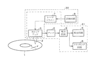
図1のブロック図に、本実施の形態にかかる光記録再生装置の主要部を示す。図1に示すように、上記光記録再生装置は、光学ピックアップ(光学系)3、アンプ4、再生回路5、トラッキング回路6、レーザドライバ7、記録回路8および微分回路9を備えている。そして、光学ピックアップ3、レーザドライバ7および記録回路8により記録部30が構成されている。また、光学ピックアップ3、アンプ4、再生回路5、トラッキング回路6、レーザドライバ7および微分回路9により再生部31が構成されている。
【0035】
上記光記録再生装置における情報の記録時には、記録回路8から出力された記録情報が、レーザドライバ7に送られる。上記レーザドライバ7は、記録情報に応じた駆動電流を光学ピックアップ3内の半導体レーザ(光源、図示せず)に送る。上記半導体レーザからは、駆動電流に応じて強度変調されたレーザビーム2(第1のレーザ光)が出射(照射)される。この出射されたレーザビーム2は、集光手段(図示せず)により光ディスク1に集光されて、光ディスク1に変形部を形成する。これにより、光ディスク1に情報の記録が行われる。
【0036】
また、上記光記録再生装置における記録された情報の再生時には、再生を指示する信号に基づいてレーザドライバ7が光学ピックアップ3内の半導体レーザに、記録時よりも弱い一定の第2レーザビーム2を出射させるように駆動電流を送る。これにより、上記半導体レーザから、記録時(第1のレーザビーム)よりも弱い第2のレーザビーム2が光ディスク1に出射される。この出射されたレーザビーム2は、光ディスク1に反射される。その反射光を、光学ピックアップ3内の検出器(図示せず)で検出して、電気信号に変換する。そして上記電気信号を、アンプ4によって増幅する。
【0037】
増幅された信号は、トラッキング回路6と微分回路9とに出力される。トラッキング回路6では、増幅された信号を基にトラッキングエラー信号を生成し、これに基づいてレーザビーム2を光ディスク1における所望のトラック(図示せず)に追従させる。また、微分回路9では増幅された信号を微分し、再生回路5に出力する。さらに、再生回路5では、微分された信号を2値化し、記録された情報の再生を行う。
【0038】
なお、本記録再生装置では、情報の劣化を防ぐために、上記記録回路8が、記録でも再生でもない、待機時と所望のトラックへとアクセスするアクセス時とには、半導体レーザより最も弱い第3のレーザビーム2が照射されるように、レーザドライバ7の駆動を制御する。これにより、常に、再生パワーのレーザビーム2が照射される構成に比して、光ディスク1における再生耐久性をより一層向上させることができる。
【0039】
ここでは、光記録再生装置は光ディスク1からの反射光を検出する構成となっているが、検出器を、光ディスク1を挟んで光学ピックアップと対向するように備えて、透過光を検出する構成としてもよい。
【0040】
ここで、本発明の前提となる本実施の形態で使用する光ディスク、および光ディスクへの情報の記録・再生方法について説明する。
【0041】
本発明者らは、貴金属酸化物層を有する光記録媒体において、貴金属酸化物層を記録層として用い、この層に解像限界より小さい微小な記録マーク又は解像限界より大きいが解像限界に近い微小な記録マークを記録し、閾値以上の再生パワーで再生を行うことによって、超解像再生において、高いCNR(Carrier to noise ratio)が得られると共に、高い再生耐久性が得られることを見出した。この光記録媒体、すなわち光ディスクについて以下に説明する。
【0042】
図2および図3に、本実施の形態で使用する光記録媒体が形成された円盤状の光ディスク1の断面図を示す。
【0043】
上記光ディスク1は、基板14上に、第1誘電体層15、貴金属酸化物層16、第2誘電体層17、光吸収層(相変化材料層)18、および第3誘電体層19をこの順に備えている。また、第1誘電体層15、貴金属酸化物層16、第2誘電体層17、光吸収層18、および第3誘電体層19により光記録媒体が構成される。なお、光ディスク1の構造は、これに限定されるものではない。
【0044】
光ディスク1におけるそれぞれの部材の厚さと材料は、基板14が0.6mmのポリカーボネート、第1誘電体層15が130nmのZnS−SiO2、貴金属酸化物層16が4nmの酸化白金、第2誘電体層17が40nmのZnS−SiO2、光吸収層18が60nmのAg−In−Sb−Te、第3誘電体層19が100nmのZnS−SiO2である。
【0045】
また、上記基板14には、グルーブ21・21・21…と、ランド22・22…とが螺旋状に形成されている。ランド22およびグルーブ21の幅は、どちらも0.6〜0.7μmである。上記ランド22とは、隣り合うグルーブ21間の部分である。
【0046】
続いて、図2および図3を参照して、光ディスク1への情報の記録について説明する。なお、図2には光ディスク1における径方向(図1に示すx方向)の断面の構造を示し、図3には、光ディスク1における周方向(図1に示すy方向)の断面、言い換えると光ディスク1のグルーブ21に沿って切断した断面の構造を示す。
【0047】
上記で示した貴金属酸化物層16を含む光ディスク1に、第1のレーザビーム2(記録光)を集光して照射すると、空洞あるいはガス球よりなる変形部20を形成することにより情報を記録することができる。この変形部20は、上記グルーブ21に沿って形成される。この第1のレーザビーム2は、例えば、光の波長λと開口数NAを備える光学ピックアップ(光学系)から照射すればよい。前記ピックアップから照射された一定の径(λ/NA)の集光スポットを使用するが、照射されるレーザ光の照射時間を適切に短くするか、あるいは下げることにより、上記空洞あるいはガス球よりなる変形部20を、上記グルーブ21沿う方向においてλ/(4×NA)よりも短くすることができる。上記空洞あるいはガス球よりなる変形部20が生じる理由は、貴金属酸化物層16に第1のレーザビーム2を照射することによって、貴金属酸化物層16の貴金属酸化物が分解(爆発)し、この分解で発生した酸素ガスが、貴金属酸化物層16内で体積膨張を起こして貴金属酸化物層16を変形させると共に、第2誘電体層17と光吸収層18とを押し上げた結果、形成されたと考えられる。つまり、上記空洞あるいはガス球よりなる変形部20は、爆発後、元に戻らず保持され、情報の記録マークとなる。なお、上記第1のレーザビームは、貴金属酸化物層に変形部が形成される照射光強度、言い換えれば貴金属酸化物が分解(爆発)する照射光強度を少なくとも有するものとする。
【0048】
次に、上記光ディスクからの情報の再生方法について説明する。
【0049】
上記光ディスク1に、第2のレーザビーム2(再生光)を照射し、その光ディスク1における反射光又は透過光を検出して、上記変形部20から信号を読み出し、情報を再生することができる。なお、上記第2のレーザビームは、上記第1のレーザビームよりも照射光強度の弱い、貴金属酸化物が分解しない程度の照射光強度を有するものとする。しかしながら、この第2のレーザビームを照射し続けると、空洞あるいはガス球からなる変形部20が次第に劣化し、情報が破壊される。そこで、待機時あるいは上記光ディスク1の所望のトラックへのアクセス時には、光ディスク1に、第1のレーザビームおよび第2のレーザビームよりも照射光強度の弱い第3のレーザビーム2を照射することにより、第2のレーザビームの照射による空洞あるいはガス球よりなる変形部20の劣化を抑える。また、この第3のレーザビーム2は、前記空洞あるいはガス球よりなる変形部20を含むトラックをトラッキングするのに十分な照射光強度を有するように設定することが好ましい。
【0050】
なお、上記第1〜3のレーザビームは同一の光学ピックアップ(光学系)から出力され、強度が異なるビームである。これに限らず、記録、再生、トラッキングのために別々のビームを用いる、いわゆるマルチビームの場合には、異なる光学系から第1〜第3のレーザビームを出力してもよい。
【0051】
上述のように、第3のレーザビームの照射によって、空洞あるいはガス球からなる変形部20の劣化を抑えることができるが、記録された情報を何度も再生して利用するような用途では、やはり第2のレーザビームの照射によって次第に空洞あるいはガス球が劣化する。したがって、第2のレーザビームの照射に耐え得る空洞あるいはガス球よりなる変形部20による記録が必要であった。
【0052】
本発明者らは、上記の光ディスク1への情報の記録・再生について以下のような実験により検証している。
【0053】
上記光ディスク1に対して、本発明者らは、波長λ=635nmの半導体レーザと開口数NA=0.6の対物レンズ11とからなる光学系を用いて、照射光強度(以下、レーザパワー或いはパワーと称する)8〜14mW、線速度6m/s、記録周波数15MHzの信号の記録を試みた。つまり、レーザビーム2のパワーを、8〜14mWの記録パワーと1mWのバイアスパワーとして、周波数15MHzで強度変調した。
【0054】
その結果、貴金属酸化物層16には、記録パワーのレーザビーム2の照射位置に対応して、空洞或いはガス球よりなる変形部(記録マーク)20が形成され、光吸収層18には、全面的に結晶化が起こった。
【0055】
これは、貴金属酸化物層16及び光吸収層18に、所定のパワー以上(ここでは、8mWより大きい)のレーザビーム2を照射することで、貴金属酸化物層16では貴金属酸化物の分解(爆発)が起こり、貴金属酸化物の分解で発生した酸素ガスが、貴金属酸化物層16内で体積膨張を起こして貴金属酸化物層16を変形させると共に、第2誘電体層17と光吸収層18とを押し上げた結果、貴金属酸化物層16に、空洞或いはガス球よりなる変形部20が形成されたと考えられる。
【0056】
透過型電子顕微鏡にて観察した結果、変形部20の長さは、記録パワーのレーザビーム2の照射時間に対応しており、200nmであることを確認した。ここで用いた半導体レーザの波長λと対物レンズの開口数NAとより、変形部20の解像限界(λ/(4×NA))はおよそ260nmとなる。したがって、ここで形成された変形部20は、解像限界以下の寸法となる。
【0057】
次に、上記半導体レーザのパワーを4mW(再生パワー)にして、貴金属酸化物層16に形成した変形部20の再生を試みた。その結果、この変形部20は解像限界以下の記録ピッチであるにもかかわらず、44dBもの高いCNR(Carrier to Noise Ratio)が得られ、実用上、十分なCNRを得られることを確認した。さらに、変形部20の長さを130nmへ短くしても、40dBの高いCNRが得られた。後述するが、この高いCNRをもつ読み出し信号における低周波数帯域のノイズを、微分回路によって低減し、高いSNRを得ることができる。
【0058】
また、本発明者らは、上記光ディスク1に対して、4mWの再生パワーにて連続再生を行うと、1万回前後の繰り返し再生が可能であることも確認した。さらに再生パワー照射し続けると、貴金属酸化物層16に形成された変形部20に劣化が生じ、再生品質が低下することも確認した。
【0059】
さらに、本発明者らは、光記録媒体における貴金属酸化物層16を酸化白金から酸化銀に代えた光ディスク1も試作し、上記と同様に記録再生を試みた。その結果、酸化銀よりなる貴金属酸化物層16であっても、酸化白金からなる貴金属酸化物層16と同様に、所定以上の記録パワーのレーザビーム2を照射することで、貴金属酸化物層16に空洞或いはガス球よりなる変形部20が形成され、再生信号においては、高いCNRが得られることを確認した。
【0060】
しかしながら、貴金属酸化物層16を酸化銀より形成した光ディスク1では、貴金属酸化物層16に酸化白金を用いた上記光ディスク1に比べて、再生信号の劣化の速度、つまり、変形部20に再生のために照射されるレーザビーム2にて、変形部20にて記録された情報が劣化する速度が速いことが確認された。このことより、光記録媒体における貴金属酸化物層16には、酸化白金を使用することで、高いCNRと高い再生耐久性が得られることを実験にて確認した。つまり、本実施の形態における貴金属酸化物層は、酸化白金からなることが好ましい。
【0061】
なお、本発明者らは、酸化銀よりなる貴金属酸化物層を用いた光記録媒体に対して記録/再生を行うことを公開している(特許文献2参照)。しかしながら、これにおいては、記録時のレーザパワーが上記の範囲よりも弱いため、貴金属酸化物層16には、空洞或いはガス球よりなる上記変形部20は形成されていない。そして、これを上記と同じ再生パワーで読み出すと、30〜40dBのCNRが得られるものの、数分で信号が劣化し、実用に耐え得る耐久性を得ることができなかった。なお、上記の光吸収層18を他の材料に置き換えても、大きなCNRは得られなかった。
【0062】
また、上述の通り、光ディスクに記録した情報の再生回数が1万回に向上した程度では、上記光ディスクの使用範囲が限定され、情報の保存のみにしか使用できない。これに対して本発明者らは、さらに再生回数を増加させることができる、光ディスクへの情報の記録方法を下記の通り見出した。
【0063】
光ディスク1への情報の記録方法は、光ディスクへ記録マークを形成する際の、直前と直後とで補助照射を行う方法である。つまり、照射するレーザビームのレーザパルスの波形を変化させ、記録マークの形成の直前と直後とでレーザビームの照射光強度を小さくする。これにより、光ディスク1に形成される記録マークの耐久性を高めることができる。さらに、記録マークと記録マークとの間に再生限界(λ/(4×NA))より小さいスペースを形成する場合には、補助照射を行わず、照射光強度を補助照射より小さくする(または0にする)。あるいは、補助照射の時間を短くしてもよい。つまり、記録マークの形成の直前と直後に比べてさらに照射エネルギーを少なくするために、補助照射の照射光強度を減らすか、あるいは照射時間を減らす。これにより、大きな再生信号波形を得ることができ、再生時の高いSNRを達成することができる。
【0064】
なお、上記補助照射は、上記第4のレーザビーム(補助照射光)により行う。また、この第4のレーザビームは、その照射光強度が第1のレーザビームよりも低く設定されている。本実施の形態では、この第4レーザビームは、上記第1〜3のレーザビームと同一の光学ピックアップ(光学系)から出力され、強度が異なるビームである。これに限らず、上記のように異なる光学系から第1〜第4のレーザビームを出力してもよい。この第4のレーザビームについても、上記記録回路8により照射光強度が制御されている。本光記録再生装置の光学ピックアップ3は、種々の強度を有する照射光を発する記録手段、補助照射手段、再生手段の機能を兼ね備えていると言える。
【0065】
この記録方法について、図4を参照して以下にさらに詳細に説明する。
【0066】
図4において、M1からM6は、光ディスク1上に形成された記録マークとしての個々の変形部20を示し、S1からS7は、この記録マークに挟まれたスペースを示している。また、図4において、上記記録マークM1〜M6及び、スペースS1〜S7の下側には、それぞれの記録マークおよびスペースを形成するときのレーザビームの各照射光強度(レーザパワー)P1、P4、P5を模式的に波形として示している。なお、上記の波形では、各照射光強度P1、P4、P5の強度の差をその高さによって表している。また、上記波形の横方向の長さは、光ディスク1の周方向(図1に示すy方向)の長さを表しており、この長さは各レーザパワーでの照射時間に比例する。本実施の形態では、マークポジション記録を採用しているため、ほぼ同一の形状の記録マークを形成している。したがって、各照射光強度P1における、上記波形の横方向の長さは、同じ長さに設定している。
【0067】
図4に示すように、記録マークM1〜M6を記録するときには、光学ピックアップ3から照射されるレーザビームは、第1のレーザビーム2(記録光)であり、その照射光強度はP1である。スペースS1〜S7を置くときには、光学ピックアップ3から照射されるレーザビームは、第5のレーザビーム2であり、その照射光強度はP5である。ここで、第5のレーザビームの照射光強度P5は、再生時に使用する第2のレーザビームの照射高強度P2と同じとする。さらに、上記記録マークM1〜M6形成の直前及び直後には、照射光強度がP4である第4のレーザビーム2(補助照射光)の補助照射が行われる。この補助照射によって、記録マークとしての変形部20の形状が安定化し、照射光強度がP2である第2のレーザビーム2による読み出し時に上記記録マークM1〜M6が劣化することを防止することができる。このように、記録マークの形状が安定すれば、読み出し時に大きな信号が得られ、十分なSNRを得ることができるとともに、繰り返し再生における耐久性を向上させることができる。
【0068】
なお、本実施の形態においては、上記スペースS1〜S7を置くときの第5のレーザビームにおける照射光強度P5を読み出し時の第2のレーザビームにおける照射光強度と同じにしているが、これらの照射光強度は必ずしもこれに限定されることはなく、P5よりも低くしても構わない。
【0069】
上記第4のレーザビームによって補助照射が行われる時間は、解像限界(λ/4NA)よりも短く設定することが好ましく、本実施の形態においては、上述の最短マークの長さ(200nm)形成される時の照射時間と同じ時間とした。これによって、記録マークM1〜M6周辺の温度が過度に上昇するのを避けることができ、変形領域(変形部)である記録マークが必要以上に大きくなってしまうことを防止することができた。
【0070】
また、本実施の形態においては、第1、第4、第5のレーザビーム2における各照射光強度の適切な値は、P1=8〜14mW、P2=6〜8mW、P3=1〜4mWであった。即ち、上記各照射光強度の大きさは、P1>P4≧P5となることが好ましい。これによって、照射光強度P4である第4のレーザビーム2による補助照射が適切に行われ、耐久性をより向上させることができる。
【0071】
さらに、S3、S4、S6のように、上記スペースの長さ(即ち、隣接する記録マークの間隔)が解像限界(λ/4NA)よりも短い場合は、補助照射を行わず、照射光強度をP5(あるいは照射光強度=0)とすると、再生時に高いSNRを得ることができた。即ち、図4に示すように、T1〜T6においては補助照射(照射光強度=P4)を行い、T7〜T9においては補助照射を行わない(即ち、照射光強度=P5)ようにすると、ディジタル復調に適した波形であって、しかも大きな信号が得られ、高いSNRを得られることが確認された。これによって、隣接する2つの記録マークの間隔、すなわちスペースの長さが、λ/4NAよりも短い場合の余分な過熱を抑え、記録マークが過度に大きくなることを防止することができ、より適切な記録マークの形成を実現することができる。
【0072】
以上のように、本実施の形態で使用する光ディスク1への記録方法と、その特長について述べた。しかしながら、上記に示した光ディスク1への情報の記録方法においては、情報の再生方法によっては、SNRが低下する可能性がある。そこで、このSNRの低下する原因について、図5および図6を参照して説明する。
【0073】
まず、図5に、上記光ディスクへの情報の記録直後に、記録した情報に対して読み出し信号の電力スペクトルを測定した結果を示す。この測定は、周波数15MHzの信号を線速度6m/s、レーザビームのパワーが10mWの条件にて記録した後、レーザビームのパワーを1mWに下げ、市販のスペクトラムアナライザに読み出し信号を入力して行った。上記10mWのレーザビームが第1のレーザビームに相当し、1mWのレーザビームが第3のレーザビームに相当する。なお、記録される信号は15MHzのキャリア信号となり、記録マークとスペースの長さは共に200nmであるため、解像限界よりも短い。このため、記録時は、図4における第1の照射光強度P1と、第5の照射光強度P5とを使用し、第4の照射光強度P4は使用しなかった。光ディスクに記録されたマークの長さは0.2μmであり、解像限界よりも短かく、読み出しのためのレーザビームのパワーが1mWであって、レーザビームのパワーが低すぎるため、超解像効果は得られず、15MHzのキャリア周波数には、読み出し信号のピークは現れない。
【0074】
図6は、読み出しのためのレーザパワーを第2のレーザビームの強度に相当する4mWに上げたときの、スペクトルの測定結果である。超解像効果が現れ、15MHzのキャリア周波数において、44dBのCNRが得られた。したがって、キャリア周波数近傍において実用的な信号品質が得られた。しかし、10MHz以下の低域においては、読み出しのためのレーザパワーが1mWの条件(図5)と比較してノイズが大きく上昇した。つまり、これは、レーザパワーの上昇に伴うノイズ信号の増幅効果に比べて、遥かに大きな上昇である。
【0075】
以上のことより、本発明者らの実験によれば、15MHzのキャリア信号を超解像効果によって読み出しできるが、これに伴って低域のノイズも上昇するため、SNRが低下するという問題点があることが判った。なお、上記は電力スペクトルの測定を行うために、記録される信号は15MHzのキャリア信号とし、記録マークとスペースの長さは共に200nmとしたが、実際のデータの記録時は、この長さに限らず、変復調に応じて複数の種類の長さとなる。
【0076】
以下には、本発明の光記録再生方法、光再生方法、光記録再生装置および光再生装置の構成、動作と特長に絞って説明する。
【0077】
つまり、本実施の形態では、図1に示した微分回路9によって信号を微分して再生すると、貴金属酸化物層を備えた光ディスクにおいて発生した低域ノイズが低減され、SNRを上げて信号を再生できることが判った。図7を用いて、本実施の形態にかかる光ディスクの具体的な再生方法について詳しく述べる。ここでは、記録マークはいわゆるマークポジション法に基づいて記録することとする。
【0078】
上記マークポジション法では、光ディスクに形成された記録マークの位置(中心位置)が「1」となるようにデータが記録される。つまり、再生時に光ディスクにおける記録マークの位置を検出して、これを「1」の信号として再生する。
【0079】
本実施の形態では、光ディスクに形成された記録マーク(変形部)を第2のレーザビーム(たとえば4mW)にて読み出し、図7に示すように、記録マークの位置に対応した読み出し波形(信号)を得る。この読み出し波形を、上記の微分回路9に通し、微分波形を得る。この微分波形をヒステリシスコンパレータにて2値化して、2値波形を得る。この2値波形における立下りが記録マークの位置に対応している。
【0080】
このマークポジジョン記録および微分回路を用いた再生方法は従来から良く知られている方法である。しかしながら、上記に示した超解像効果を発揮して飛躍的に記録密度を向上できる貴金属酸化物層を備えた光ディスク1では、読み出し信号の低域周波数にて大きなノイズが生じ、SNRが低下することが問題となっている。これに対して、本実施の形態では、読み出し波形を微分回路で微分することにより低域周波数におけるノイズを低減することができ、SNRを向上させることができるという大きな効果を得られることが判ったのである。また、光ディスクにマークポジジョン法に基づいて記録マークを形成することにより情報を記録し、該記録マークから読み出しを行うことにより、より一層SNRを向上させることができることが判ったのである。
【0081】
さらなる実験では、さらに記録マークの長さを短くし、0.13μmにおいても2値波形が得られ、十分に再生可能なことが判った。図11には、この時の読み出し信号の波形と2値信号の波形を示す。この図11より、高いSNRを維持しながら、再生に十分な品質の2値信号が得られているのが判る。この記録密度は、市販の高密度記録ディスクであるDVD(Digital Video Disc)における線密度の3倍に相当する(DVDの記録マーク長は0.4μmである)。つまり、超解像効果を維持したまま低域ノイズを低減し、SNRを向上させた結果、従来の記録密度を大きく上回る記録密度を得ることができることが判る。また、光ディスク(貴金属酸化物層)に記録されたマークはほぼ円形であり、トラック密度方向(図1におけるx方向)の径も0.13μmであった。マークポジション記録の場合は、光ディスクに記録されたマークの径が全て同じであるため、トラック密度を向上させることができる。したがって、光ディスクにおける面密度をさらに大きくすることが可能である。
【0082】
また、上記微分回路のカットオフ周波数をfd(Hz)、回折限界の周波数fl(Hz)とすると、以下の関係となる。実験の結果、良好なSNRを確保するためには、(1/5)×fl≦fd≦10×flの関係となった。さらに、ジッタやエラーを適切に低減するためには、fl≦fd≦5×flとなった。なお、回折限界の周波数flは、fl=線速度×(2×NA)/λにて定義する。また、前記の式ではHz(ヘルツ)の単位で関係式を示したが、これに限らず、光記録媒体上の長さの単位であるm(メートル)を用いた関係式に変換しても構わない。
【0083】
なお、図1に示した微分回路9は、例えば、図8に示す差分回路9’に置き換えることができる。この差分回路9’では、増幅された読み出し信号S1は遅延回路91と差動増幅器92のプラス入力端子に入力される。遅延回路91の出力S2は差動増幅器92のマイナス入力端子に入力される。そして、差動増幅器92の出力S3は、図1における再生回路5に送られ、2値化されて再生される。
【0084】
図9は図8に示した差分回路9’における動作を示す図である。読み出し信号S1と遅延回路91によって時間Tだけ遅延された読み出し信号S2を差動増幅器92にて差動増幅すると、S3は読み出し信号S1のピークにてゼロクロスする信号となり、実質的に微分回路と同等な働きをする。また、遅延時間Tの逆数をとった周波数F(=1/T)に対して十分に低い周波数では、実質的に同じ信号同士を差動することになり、出力信号S3には出力は低下する。したがって、この差分回路9’は、周波数Fよりも十分に低い周波数をカットするハイパスフィルターとなり、上述の低域のノイズを低減することができる。したがって、微分回路9に限らず、マークポジション記録されたマークを再生可能な回路であれば、同様な効果が得られる。
【0085】
さらに、上記マークポジション記録を行うと、マークの長さが一定となり、記録が容易となる。たとえば、後述するマークエッジ記録においてはマークの長さが複数の種類となり、従来から、このマークの長さ毎に記録レーザパルスの波形を細かく制御するいわゆる記録ストラテジの技術が必要であった。この記録ストラテジ技術は、高密度記録なればなるほど、レーザとその駆動回路に負担が大きくなり、技術的な限界に近づいている。それに比べて、本発明の貴金属酸化物層を含む記録媒体にマークエッジ記録を行うと、マークの長さが一定となり、レーザとその駆動回路に負担を与えることなく、容易に記録密度が向上する装置が提供可能である。
【0086】
また、ここまでは貴金属酸化物層を備えるディスク(光ディスク1)において、マークポジション記録を行った場合に最大の効果が得られることを示したが、これに限らず、いわゆるマークエッジ記録においても低域のノイズを低減することができる。図10に、貴金属酸化物層を備えるディスク(光ディスク1)に形成した、マークエッジ記録を適用した場合の動作を示す図である。記録マークを読み出すと、読み出し波形においては、記録マークのエッジでハイレベルとローレベルとの間で反転する。この読み出し波形を微分すると1階微分波形が得られ、さらに微分すると2階微分波形が得られる。この2階微分波形のゼロクロス点を検出し2値化すると、記録マークに対応した2値波形が得られる。
【0087】
したがって、本発明はマークポジション記録に限定されるものではなく、マークエッジ記録においても適用可能である。しかしながら、このマークエッジ記録では、2階微分が必要である。2階微分を行うと1階微分に比べて高域周波数のノイズが相対的に大きくなりSNRが低下しやすい。つまり、低域周波数のノイズを低減しても、逆に高域周波数のノイズが大きくなりやすく、結局SNRの向上は小さい。したがって、貴金属酸化物層を備えるディスクにおいては、マークポジション記録が好ましい。
【0088】
【発明の効果】
以上のように、本発明の光記録再生方法は、貴金属酸化物層を含む光記録媒体に光を照射して、情報を記録再生する光記録再生方法であって、該貴金属酸化物層に記録光を照射して変形部を形成することにより情報を光記録媒体に記録し、上記光記録媒体に照射した再生光の反射光または透過光を検出することにより上記変形部から信号を読み出し、上記信号を微分することにより情報を再生する方法である。
【0089】
上記の方法によれば、貴金属酸化物層を含む光記録媒体に変形部を形成することによって記録し、その変形部から情報を読み出して再生することができる。この読み出しの際の信号には低域周波数のノイズが含まれるが、上記信号を微分することによって低域周波数のノイズを低減することができる。これにより読み出し信号のSNRを向上させることができるという効果を奏する。
【0090】
また、本発明の光記録再生方法は、貴金属酸化物層を含む光記録媒体に光を照射して情報を記録再生する光記録再生方法であって、該貴金属酸化物層に記録光を照射して変形部を形成して、マークポジション記録により情報を光記録媒体に記録し、上記光記録媒体に照射した再生光の反射光または透過光を検出することにより上記変形部から信号を読み出し、上記信号からマークポジションを情報として再生する方法である。
【0091】
上記の方法によれば、貴金属酸化物層を含む光記録媒体に変形部を形成することによって記録し、その変形部から情報を読み出して再生することができる。この読み出しの際の信号には低域周波数のノイズが含まれるが、本方法では、マークポジション記録を採用しているため、マークの中心位置を検出すればよく、その他の部分でのノイズに依存することなく信号が再生できる。すなわち、マークを読み出した波形のピーク位置(あるいはボトム位置)を回路によって検出すればよく、読み出した波形のその他の部分でノイズが多くても、マークの位置を検出できる。これにより、読み出し信号を実質的に高いSNRによって再生することができる。
【0092】
そこで、本発明の光記録再生方法は、上記の方法に加えて、前記再生光が、前記記録光よりも強度が小さいことが好ましい。これにより、再生光の強度が記録光より小さいため、上記変形部の劣化を抑制することができるという効果を奏する。
【0093】
また、本発明の光記録再生方法は、上記の方法に加えて、前記再生光の波長をλとし、開口数をNAの集光手段を用いて該再生光を光記録媒体に照射する場合、前記記録光によって光記録媒体に記録される前記変形部の最小の長さが、λ/4NAよりも短いことが好ましい。これにより、記録密度を上げて光記録媒体に記録した情報の読み出し信号を、超解像再生効果によって増大させ、上記の微分あるいはマークポジション記録によって低域周波数のノイズを低減しながら、高いSNRで再生することができるという効果を奏する。
【0094】
また、本発明の光再生方法は、上記の課題を解決するために、貴金属酸化物層を含む光記録媒体に再生光を照射して、情報を再生する光再生方法であって、該貴金属酸化物層に光が照射されて形成された変形部によって記録された情報を、上記再生光の反射光または透過光を検出することにより上記変形部から信号を読み出し、上記信号を微分することにより情報を再生することを特徴としている。
【0095】
上記の方法によれば、貴金属酸化物層を含む光記録媒体に形成された変形部から読み出した信号を微分しているので、再生時に含まれる低域周波数のノイズをより低減することができる。これにより、読み出し信号のSNRを向上させることができる。
【0096】
また、本発明の光再生方法は、上記の方法に加えて、前記再生光の波長をλとし、開口数がNAの集光手段を用いて該再生光を光記録媒体に照射する場合、前記記録光によって光記録媒体に記録される前記変形部の最小の長さが、λ/4NAよりも短いことが好ましい。これにより、記録密度を上げて光記録媒体に記録されている情報の読み出し信号を、超解像再生効果によって増大させ、上記の微分あるいはマークポジション記録によって低域周波数のノイズを低減しながら、高いSNRで再生することができる。
【0097】
本発明の光記録再生装置は、以上のように、貴金属酸化物層を含む光記録媒体に、記録光を照射して該貴金属酸化物層に変形部を形成して情報を記録する記録部と、変形部が形成された上記光記録媒体に、光源からの光を集光手段によって集光した再生光を照射すると共に、該再生光の反射光または透過光を検出し、該変形部から信号を読み出すことにより再生する再生部とを備える光記録再生装置であって、前記再生部は、上記信号を微分する微分回路を備えている構成である。
【0098】
上記の構成によれば、貴金属酸化物層を含む光記録媒体に変形部を形成することによって記録し、その変形部から情報を読み出して再生することができる。この読み出しの際の信号には低域周波数のノイズが含まれるが、上記信号を微分することによって低域周波数のノイズを低減することができる。これにより読み出し信号のSNRを向上させることができ、実用的な再生が可能な光記録再生装置を提供することができるという効果を奏する。
【0099】
また、本発明の光記録再生装置は、以上のように、貴金属酸化物層を含む光記録媒体に、記録光を照射して該貴金属酸化物層に変形部を形成することにより情報を記録する記録部と、変形部が形成された上記光記録媒体に、光源からの光を集光手段によって集光した再生光を照射すると共に、該再生光の反射光または透過光を検出し、該変形部から信号を読み出すことにより再生する再生部とを備える光記録再生装置であって、前記記録部は、マークポジション記録により情報を光記録媒体に記録し、前記再生部は、上記信号からマークポジションを情報として再生する構成である。
【0100】
上記の構成によれば、貴金属酸化物層を含む光記録媒体に変形部を形成することによって記録し、その変形部から情報を読み出して再生することができる。この読み出しの際の信号には低域周波数のノイズが含まれるが、本光再生装置では、マークポジション記録を採用しているため、マークの中心位置を検出すればよく、その他の部分でのノイズに依存することなく信号が再生できる。すなわち、マークを読み出した波形のピーク位置(あるいはボトム位置)を回路によって検出すればよく、読み出した波形のその他の部分でノイズが多くても、マークの位置を検出できる。これにより、読み出し信号を実質的に高いSNRによって再生することができる。さらに実用的な再生が可能な光記録再生装置を提供することができるという効果を奏する。
【0101】
本発明の光記録再生装置は、上記の構成に加えて、前記再生光が、前記記録光よりも強度が小さいことが好ましい。これにより、再生光の強度が記録光より小さいため、上記変形部の劣化を抑制することができる。
【0102】
また、本発明の光記録再生装置は、上記の構成に加えて、前記再生光の波長をλとし、開口数をNAの集光手段を用いて該再生光を光記録媒体に照射する場合、前記記録光によって光記録媒体に記録される前記変形部の最小の長さが、λ/4NAよりも短いことが好ましい。これにより、記録密度を上げて光記録媒体に記録した情報の読み出し信号を、超解像再生効果によって増大させ、上記の微分あるいはマークポジション記録によって低域周波数のノイズを低減しながら、高いSNRで再生することができる。
【0103】
本発明の光再生装置は、以上のように、光源からの光を集光手段によって集光した再生光を貴金属酸化物層を含む光記録媒体に照射すると共に、該貴金属酸化物層に光が照射されて形成された変形部によって記録された情報を該再生光の反射光または透過光を検出し、該変形部から信号を読み出すことにより再生する再生部を備える光再生装置であって、上記再生部は、上記信号を微分する微分回路を備えている構成である。
【0104】
上記の構成によれば、貴金属酸化物層を含む光記録媒体に形成された変形部から読み出した信号を微分しているので、再生時に含まれる低域周波数のノイズを低減することができる。これにより読み出し信号のSNRを向上させることができ、実用的な再生が可能な光再生装置を提供することができるという効果を奏する。
【0105】
本発明の光再生装置は、上記の構成に加えて、前記集光手段の開口数をNA、前記再生光の波長をλとした場合、前記記録光によって光記録媒体に記録される前記変形部の最小の長さが、λ/4NAよりも短いことが好ましい。これにより、記録密度を上げて光記録媒体に記録した情報の読み出し信号を、超解像再生効果によって増大させ、上記の微分あるいはマークポジション記録によって低域周波数のノイズを低減しながら、高いSNRで再生することができるという効果を奏する。
【図面の簡単な説明】
【図1】本実施の形態にかかる光記録再生装置の主要部を示すブロック図である。
【図2】図1に示す光記録再生装置で使用される光ディスクを径方向で切断した断面図である。
【図3】図1に示す光記録再生装置で使用される光ディスクを周方向で切断した断面図である。
【図4】図1に示す光記録再生装置で使用される記録時のレーザパルスの波形を示す図である。
【図5】本実施の形態にかかる光記録再生装置で使用される光ディスクにおける、記録直後のノイズスペクトルを示す図である。
【図6】本実施の形態にかかる光記録再生装置で使用される光ディスクにおける、再生のノイズスペクトルを示す図である。
【図7】図1に示す光記録再生装置における微分回路の動作を示す信号波形図である。
【図8】図1に示す光記録再生装置における微分回路に代わる別の回路例を示す図である。
【図9】図8の回路の動作を示す信号波形図である。
【図10】本実施の形態にかかる光記録再生装置にてマークエッジ記録を行った場合の再生動作を示す信号波形図である。
【図11】図10における読み出し信号の波形と2値信号の波形を示す図である。
【符号の説明】
1 光ディスク(光記録媒体)
2 レーザビーム
3 光学ピックアップ
4 アンプ
5 再生回路
6 トラッキング回路
7 レーザドライバ
8 記録回路
9 微分回路
30 記録部
31 再生部[0001]
TECHNICAL FIELD OF THE INVENTION
The present invention relates to an optical recording / reproducing method, an optical reproducing method, and an optical recording method for performing at least reproduction on an optical recording medium on which a recording mark having a dimension near the diffraction limit of light and smaller than the diffraction limit of light is recorded and reproduced. The present invention relates to a reproducing apparatus and an optical reproducing apparatus.
[0002]
[Prior art]
In recent years, in order to process an enormous amount of information such as an image, a higher density of optical recording / reproducing on an optical recording medium is more required. For this reason, technical studies on reading out signals recorded at high density have been actively conducted.
[0003]
Generally, in a reading (reproducing) method using a laser beam, there is a resolution limit determined by a light diffraction limit. Assuming that the wavelength of the laser beam is λ and the numerical aperture of the objective lens is NA, the diffraction limit of light is λ / (2 × NA) and the resolution limit is λ / (4 × NA).
[0004]
That is, since the cut-off spatial frequency is (2 × NA) / λ, a recording mark row in which the length of a recording mark is the same as the length of a space between two adjacent recording marks is the spatial frequency (2 × NA). If it is equal to or less than NA) / λ, it becomes readable. In this case, the mark length (space length) corresponding to the readable spatial frequency is λ / (4 × NA). That is, a read signal cannot be obtained by reading a recording mark row having an arrangement pitch of less than λ / (2 × NA) and a mark length of less than λ / (4 × NA).
[0005]
Therefore, in order to read out a signal recorded at a high density, it is effective to make the resolution limit smaller, that is, make λ smaller and / or make NA larger. Is being done.
[0006]
On the other hand, apart from the study for reducing the resolution limit, a super-resolution recording / reproducing technology has been proposed as a technology for recording and reading a recording mark smaller than the resolution limit. As a super-resolution recording / reproducing technique, for example, a technique has been proposed in which a layer having a function of generating an opening or the like by laser irradiation is provided in a medium to substantially increase the NA in the medium.
[0007]
As an example, a method of performing super-resolution recording and reproduction by irreversibly deforming a mask film formed on a substrate is disclosed (for example, see Patent Document 1). In this publication, the optical recording medium includes a mask layer that is an alloy thin film layer containing at least one element of Ge, Ga, Te, Sn, In, Se, Sb, and As. Then, at the time of recording, the optical recording medium is irradiated with strong light to deform the irradiated portion of the alloy thin film layer to form a reproduction window, and a recording mark is formed in a recording layer below the window. . Further, at the time of reproduction, weak light is irradiated through the reproduction window to reproduce a recording mark recorded by deformation having a size equal to or smaller than the diffraction limit. These enable super-resolution recording / reproduction.
[0008]
[Patent Document 1]
Japanese Patent Application Laid-Open No. 8-185,642
[0009]
[Patent Document 2]
JP 2000-348377 A
[0010]
[Problems to be solved by the invention]
However, in the super-resolution recording / reproducing technique disclosed in the above publication, the carrier-to-noise ratio (CNR) of the reproduced signal is low, so that the signal-to-noise ratio in the entire frequency band when the digital signal is actually reproduced is reduced. This leads to a reduction in the ratio (SNR: Signal to noise ratio), which is not at a practical level. Therefore, there is a problem that it is difficult to perform high-density recording and reproduction by super-resolution recording and reproduction.
[0011]
This is because a sufficiently high SNR is finally required to read a recording mark having a size smaller than the resolution limit at a linear velocity of a practical optical disc. In order to finally increase the SNR, it is particularly important to improve the CNR and reduce noise in the reproduction frequency band. However, in super-resolution recording / reproduction, as the size of the recording mark becomes smaller than the resolution limit, the amount of signal read out gradually decreases, and the CNR decreases. Further, the reproduction frequency band becomes wider as the recording mark shrinks, and the noise power increases. That is, the SNR rapidly decreases due to the decrease in CNR and the increase in noise power. Even in the super-resolution recording / reproducing technique disclosed in the above publication, a practical level of SNR cannot be obtained because the recording mark is small.
[0012]
The present invention has been made in view of the above-described problems, and an object thereof is to provide an optical recording medium having a noble metal oxide layer, an optical recording and reproducing method having a high SNR during reproduction, an optical reproducing method, An object of the present invention is to provide an optical recording / reproducing device and an optical reproducing device.
[0013]
[Means for Solving the Problems]
The optical recording / reproducing method of the present invention is an optical recording / reproducing method for recording / reproducing information by irradiating an optical recording medium including a noble metal oxide layer with light, in order to solve the above-mentioned problem. Information is recorded on an optical recording medium by irradiating the object layer with recording light to form a deformed portion, and a signal from the deformed portion is detected by detecting reflected light or transmitted light of reproduction light applied to the optical recording medium. And reproducing the information by differentiating the signal.
[0014]
According to the above method, recording can be performed by forming a deformed portion on the optical recording medium including the noble metal oxide layer, and information can be read from the deformed portion and reproduced. The signal at the time of this reading contains low-frequency noise. By differentiating the signal, low-frequency noise can be reduced. Thereby, the SNR of the read signal can be improved.
[0015]
An optical recording / reproducing method according to the present invention is an optical recording / reproducing method for recording / reproducing information by irradiating an optical recording medium including a noble metal oxide layer with light, in order to solve the above-mentioned problem. The layer is irradiated with recording light to form a deformed portion, information is recorded on an optical recording medium by mark position recording, and the reflected light or transmitted light of the reproduction light applied to the optical recording medium is detected to detect the deformation. A signal is read from the unit, and a mark position is reproduced as information from the signal.
[0016]
According to the above method, recording can be performed by forming a deformed portion on the optical recording medium including the noble metal oxide layer, and information can be read from the deformed portion and reproduced. The signal at the time of this read contains low-frequency noise, but since this method employs mark position recording, it is sufficient to detect the center position of the mark, and it depends on noise in other parts. The signal can be reproduced without performing. That is, the peak position (or bottom position) of the waveform from which the mark has been read may be detected by a circuit, and the position of the mark can be detected even if there is much noise in other portions of the read waveform. As a result, the read signal can be reproduced with a substantially high SNR.
[0017]
Further, the deformed portion formed in the noble metal oxide layer also has a problem of durability in that it is easily deteriorated by repeated irradiation of reproduction light for signal reading. For this reason, in the above conventional example, practical optical recording and reproduction cannot be performed in terms of durability. Furthermore, as a result, it is difficult to perform high-density recording and reproduction by super-resolution recording and reproduction.
[0018]
Therefore, in the optical recording / reproducing method of the present invention, in addition to the above method, it is preferable that the intensity of the reproduction light is lower than that of the recording light. Thus, since the intensity of the reproduction light is lower than that of the recording light, the deterioration of the deformed portion can be suppressed.
[0019]
Further, the optical recording and reproducing method of the present invention, in addition to the above method, when the wavelength of the reproduction light is λ, when irradiating the optical recording medium with the reproduction light using a NA focusing means, It is preferable that a minimum length of the deformed portion recorded on the optical recording medium by the recording light be shorter than λ / 4NA. As a result, the readout signal of the information recorded on the optical recording medium by increasing the recording density is increased by the super-resolution reproduction effect, and the low-frequency noise is reduced by the above-described differential or mark position recording while the SNR is increased. Can be played.
[0020]
Further, in order to solve the above-mentioned problems, the optical reproducing method of the present invention is an optical reproducing method for reproducing information by irradiating an optical recording medium including a noble metal oxide layer with reproducing light, and The information recorded by the deformed portion formed by irradiating the object layer with light, a signal is read from the deformed portion by detecting reflected light or transmitted light of the reproduction light, and information is obtained by differentiating the signal. It is characterized by reproducing.
[0021]
According to the above method, since the signal read from the deformed portion formed on the optical recording medium including the noble metal oxide layer is differentiated, low-frequency noise included in reproduction can be further reduced. Thereby, the SNR of the read signal can be improved.
[0022]
Further, in addition to the method described above, the optical reproducing method of the present invention, when irradiating the optical recording medium with the reproducing light using a focusing means having a wavelength of the reproducing light of λ and a numerical aperture of NA, It is preferable that the minimum length of the deformed portion recorded on the optical recording medium by the recording light is shorter than λ / 4NA. As a result, the readout signal of the information recorded on the optical recording medium by increasing the recording density is increased by the super-resolution reproduction effect, and while the low-frequency noise is reduced by the above-described differential or mark position recording, the readout signal is increased. It can be reproduced at SNR.
[0023]
The optical recording / reproducing apparatus of the present invention records information by irradiating a recording light to an optical recording medium including a noble metal oxide layer to form a deformed portion in the noble metal oxide layer in order to solve the above problem. The recording section to be formed and the optical recording medium on which the deformed section is formed are irradiated with reproduction light obtained by condensing light from a light source by condensing means, and reflected light or transmitted light of the reproduction light is detected. An optical recording / reproducing apparatus comprising: a reproducing unit for reproducing by reading a signal from a deforming unit, wherein the reproducing unit includes a differentiating circuit for differentiating the signal.
[0024]
According to the above configuration, recording can be performed by forming a deformed portion on the optical recording medium including the noble metal oxide layer, and information can be read from the deformed portion and reproduced. The signal at the time of this reading contains low-frequency noise. By differentiating the signal, low-frequency noise can be reduced. As a result, the SNR of the read signal can be improved, and an optical recording / reproducing apparatus capable of practical reproduction can be provided.
[0025]
Further, in order to solve the above-described problems, the optical recording / reproducing apparatus of the present invention irradiates recording light to an optical recording medium including a noble metal oxide layer to form a deformed portion in the noble metal oxide layer. The recording section for recording information and the optical recording medium on which the deformed section is formed are irradiated with reproduction light obtained by condensing light from a light source by condensing means, and reflected light or transmitted light of the reproduction light is detected. An optical recording / reproducing apparatus comprising: a reproducing unit that reproduces a signal by reading a signal from the deformed unit; wherein the recording unit records information on an optical recording medium by mark position recording; It is characterized in that a mark position is reproduced as information from a signal.
[0026]
According to the above configuration, recording can be performed by forming a deformed portion on the optical recording medium including the noble metal oxide layer, and information can be read from the deformed portion and reproduced. The signal at the time of this read contains low-frequency noise. However, since the present optical reproducing apparatus employs mark position recording, it is sufficient to detect the center position of the mark, and noise in other parts may be detected. The signal can be reproduced without depending on. That is, the peak position (or bottom position) of the waveform from which the mark has been read may be detected by a circuit, and the position of the mark can be detected even if there is much noise in other portions of the read waveform. As a result, the read signal can be reproduced with a substantially high SNR.
[0027]
In the optical recording / reproducing apparatus of the present invention, in addition to the above configuration, it is preferable that the intensity of the reproduction light is lower than that of the recording light. Thus, since the intensity of the reproduction light is lower than that of the recording light, the deterioration of the deformed portion can be suppressed.
[0028]
Further, the optical recording and reproducing apparatus of the present invention, in addition to the above configuration, when the wavelength of the reproduction light is λ, when irradiating the optical recording medium with the reproduction light using a numerical aperture NA condensing means, It is preferable that a minimum length of the deformed portion recorded on the optical recording medium by the recording light be shorter than λ / 4NA. As a result, the readout signal of the information recorded on the optical recording medium by increasing the recording density is increased by the super-resolution reproduction effect, and the low-frequency noise is reduced by the above-described differential or mark position recording while the SNR is increased. Can be played.
[0029]
In order to solve the above-described problems, an optical reproducing apparatus of the present invention irradiates an optical recording medium including a noble metal oxide layer with reproduction light obtained by condensing light from a light source by a condensing means, and An optical reproducing apparatus including a reproducing unit that detects reflected light or transmitted light of the reproducing light and reads out a signal from the deforming unit to reproduce information recorded by the deforming unit formed by irradiating the layer with light. The reproducing unit includes a differentiating circuit for differentiating the signal.
[0030]
According to the above configuration, the signal read from the deformed portion formed on the optical recording medium including the noble metal oxide layer is differentiated, so that low-frequency noise included in reproduction can be reduced. As a result, the SNR of the read signal can be improved, and an optical reproducing device capable of practical reproduction can be provided.
[0031]
The optical reproducing apparatus according to the present invention, in addition to the above-described configuration, wherein, when the numerical aperture of the condensing means is NA and the wavelength of the reproducing light is λ, the deformation section recorded on the optical recording medium by the recording light. Is preferably shorter than λ / 4NA. As a result, the readout signal of the information recorded on the optical recording medium by increasing the recording density is increased by the super-resolution reproduction effect, and the low-frequency noise is reduced by the above-described differential or mark position recording while the SNR is increased. Can be played.
[0032]
BEST MODE FOR CARRYING OUT THE INVENTION
One embodiment of the present invention will be described below with reference to FIGS.
[0033]
First, an optical recording / reproducing apparatus according to the present invention for recording / reproducing information on / from an optical disk (optical recording medium) 1 will be described. The detailed structure of the
[0034]
FIG. 1 is a block diagram showing a main part of an optical recording / reproducing apparatus according to the present embodiment. As shown in FIG. 1, the optical recording / reproducing apparatus includes an optical pickup (optical system) 3, an
[0035]
When information is recorded in the optical recording / reproducing apparatus, the recorded information output from the
[0036]
When reproducing the recorded information in the optical recording / reproducing apparatus, the
[0037]
The amplified signal is output to the
[0038]
In the present recording / reproducing apparatus, in order to prevent the information from deteriorating, the
[0039]
Here, the optical recording / reproducing apparatus is configured to detect the reflected light from the
[0040]
Here, an optical disc used in the present embodiment, which is a premise of the present invention, and a method of recording and reproducing information on the optical disc will be described.
[0041]
The present inventors, in an optical recording medium having a noble metal oxide layer, using a noble metal oxide layer as a recording layer, this layer has a small recording mark smaller than the resolution limit or larger than the resolution limit but the resolution limit. It has been found that by recording a very small recording mark and performing reproduction with a reproduction power equal to or higher than a threshold, a high CNR (Carrier to noise ratio) and a high reproduction durability can be obtained in super-resolution reproduction. Was. The optical recording medium, that is, the optical disk will be described below.
[0042]
2 and 3 are cross-sectional views of a disc-shaped
[0043]
In the
[0044]
The thickness and the material of each member in the
[0045]
.. And the
[0046]
Next, recording of information on the
[0047]
When the first laser beam 2 (recording light) is condensed and irradiated onto the
[0048]
Next, a method of reproducing information from the optical disc will be described.
[0049]
By irradiating the
[0050]
The first to third laser beams are output from the same optical pickup (optical system) and have different intensities. However, the present invention is not limited to this. In the case of a so-called multi-beam in which separate beams are used for recording, reproduction, and tracking, the first to third laser beams may be output from different optical systems.
[0051]
As described above, the irradiation of the third laser beam can suppress the deterioration of the
[0052]
The present inventors have verified the recording and reproduction of information on the
[0053]
With respect to the
[0054]
As a result, a deformed portion (recording mark) 20 formed of a cavity or a gas sphere is formed on the noble
[0055]
This is because the noble
[0056]
As a result of observation with a transmission electron microscope, it was confirmed that the length of the
[0057]
Next, the power of the semiconductor laser was set to 4 mW (reproduction power), and reproduction of the
[0058]
The present inventors have also confirmed that if the
[0059]
Furthermore, the present inventors also prototyped the
[0060]
However, in the
[0061]
The present inventors have disclosed that recording / reproduction is performed on an optical recording medium using a noble metal oxide layer made of silver oxide (see Patent Document 2). However, in this case, since the laser power at the time of recording is weaker than the above range, the
[0062]
Further, as described above, if the number of times of reproduction of the information recorded on the optical disk is increased to 10,000 times, the use range of the optical disk is limited, and the information can be used only for storing information. On the other hand, the present inventors have found a method of recording information on an optical disk, which can further increase the number of times of reproduction, as follows.
[0063]
The method of recording information on the
[0064]
The auxiliary irradiation is performed by the fourth laser beam (auxiliary irradiation light). The fourth laser beam has an irradiation light intensity set lower than that of the first laser beam. In the present embodiment, the fourth laser beam is a beam that is output from the same optical pickup (optical system) as the first to third laser beams and has a different intensity. The present invention is not limited to this, and the first to fourth laser beams may be output from different optical systems as described above. For the fourth laser beam, the
[0065]
This recording method will be described in more detail below with reference to FIG.
[0066]
In FIG. 4, M1 to M6 indicate individual
[0067]
As shown in FIG. 4, when recording the recording marks M1 to M6, the laser beam irradiated from the
[0068]
In the present embodiment, the irradiation light intensity P5 of the fifth laser beam at the time of placing the spaces S1 to S7 is the same as the irradiation light intensity of the second laser beam at the time of reading. The irradiation light intensity is not necessarily limited to this, and may be lower than P5.
[0069]
The time during which the auxiliary irradiation is performed by the fourth laser beam is preferably set to be shorter than the resolution limit (λ / 4NA). In this embodiment, the length of the shortest mark (200 nm) is set. The irradiation time was the same as the irradiation time. As a result, it was possible to prevent the temperature around the recording marks M1 to M6 from excessively rising, and to prevent the recording mark, which is a deformed area (deformed portion), from becoming unnecessarily large.
[0070]
Further, in the present embodiment, appropriate values of the irradiation light intensities of the first, fourth, and
[0071]
Further, as in S3, S4, and S6, when the length of the space (that is, the interval between adjacent recording marks) is shorter than the resolution limit (λ / 4NA), the auxiliary irradiation is not performed and the irradiation light intensity is not increased. Is P5 (or irradiation light intensity = 0), a high SNR can be obtained during reproduction. That is, as shown in FIG. 4, when the auxiliary irradiation (irradiation light intensity = P4) is performed in T1 to T6 and the auxiliary irradiation is not performed in T7 to T9 (that is, irradiation light intensity = P5), the digital It was confirmed that the waveform was suitable for demodulation, a large signal was obtained, and a high SNR was obtained. Accordingly, when the interval between two adjacent recording marks, that is, the length of the space is shorter than λ / 4NA, excessive overheating can be suppressed, and the recording marks can be prevented from becoming excessively large. It is possible to realize the formation of a simple recording mark.
[0072]
As described above, the recording method on the
[0073]
First, FIG. 5 shows a result of measuring a power spectrum of a read signal for the recorded information immediately after recording the information on the optical disc. This measurement is performed by recording a signal with a frequency of 15 MHz at a linear velocity of 6 m / s and a laser beam power of 10 mW, then reducing the laser beam power to 1 mW and inputting a readout signal to a commercially available spectrum analyzer. Was. The 10 mW laser beam corresponds to the first laser beam, and the 1 mW laser beam corresponds to the third laser beam. The signal to be recorded is a carrier signal of 15 MHz, and the length of both the recording mark and the space is 200 nm, which is shorter than the resolution limit. Therefore, at the time of recording, the first irradiation light intensity P1 and the fifth irradiation light intensity P5 in FIG. 4 were used, and the fourth irradiation light intensity P4 was not used. The length of the mark recorded on the optical disc is 0.2 μm, which is shorter than the resolution limit, the power of the laser beam for reading is 1 mW, and the power of the laser beam is too low. No effect is obtained, and no peak of the read signal appears at the carrier frequency of 15 MHz.
[0074]
FIG. 6 is a spectrum measurement result when the laser power for reading is increased to 4 mW corresponding to the intensity of the second laser beam. A super-resolution effect appeared, and a CNR of 44 dB was obtained at a carrier frequency of 15 MHz. Therefore, practical signal quality was obtained near the carrier frequency. However, in the low frequency range of 10 MHz or less, the noise increased greatly as compared with the condition (FIG. 5) in which the laser power for reading was 1 mW. That is, this is a much larger increase than the effect of amplifying the noise signal with the increase in the laser power.
[0075]
From the above, according to the experiments of the present inventors, a 15 MHz carrier signal can be read out by the super-resolution effect. However, since the low-frequency noise also increases, the SNR decreases. I found it to be. In the above, in order to measure the power spectrum, the signal to be recorded is a carrier signal of 15 MHz, and the length of the recording mark and the space are both 200 nm. The length is not limited to a plurality of types depending on the modulation and demodulation.
[0076]
Hereinafter, the optical recording / reproducing method, the optical reproducing method, the optical recording / reproducing apparatus, and the configuration, operation and features of the optical reproducing apparatus according to the present invention will be described in detail.
[0077]
That is, in the present embodiment, when the signal is differentiated and reproduced by the differentiating circuit 9 shown in FIG. 1, the low-frequency noise generated in the optical disk having the noble metal oxide layer is reduced, and the signal is reproduced by increasing the SNR. I can do it. With reference to FIG. 7, a specific reproduction method of the optical disc according to the present embodiment will be described in detail. Here, the recording mark is recorded based on a so-called mark position method.
[0078]
In the mark position method, data is recorded such that the position (center position) of a recording mark formed on an optical disk is "1". That is, the position of the recording mark on the optical disk is detected during reproduction, and this is reproduced as a "1" signal.
[0079]
In the present embodiment, a recording mark (deformed portion) formed on an optical disc is read by a second laser beam (for example, 4 mW), and as shown in FIG. 7, a read waveform (signal) corresponding to the position of the recording mark Get. This readout waveform is passed through the differentiating circuit 9 to obtain a differentiated waveform. This differential waveform is binarized by a hysteresis comparator to obtain a binary waveform. The falling edge of the binary waveform corresponds to the position of the recording mark.
[0080]
The mark position recording and reproducing method using the differentiating circuit are well-known methods. However, in the
[0081]
In a further experiment, it was found that the length of the recording mark was further shortened, a binary waveform was obtained even at 0.13 μm, and it was possible to sufficiently reproduce the waveform. FIG. 11 shows the waveform of the read signal and the waveform of the binary signal at this time. From FIG. 11, it can be seen that a binary signal of sufficient quality for reproduction is obtained while maintaining a high SNR. This recording density corresponds to three times the linear density of a DVD (Digital Video Disc) which is a commercially available high-density recording disk (the recording mark length of the DVD is 0.4 μm). That is, it is understood that as a result of reducing the low-frequency noise while maintaining the super-resolution effect and improving the SNR, it is possible to obtain a recording density much higher than the conventional recording density. The mark recorded on the optical disk (noble metal oxide layer) was substantially circular, and the diameter in the track density direction (x direction in FIG. 1) was 0.13 μm. In the case of mark position recording, since the diameters of the marks recorded on the optical disk are all the same, the track density can be improved. Therefore, it is possible to further increase the surface density of the optical disc.
[0082]
Further, the cutoff frequency of the differentiating circuit is represented by f d (Hz), diffraction-limited frequency f l (Hz), the following relationship is obtained. As a result of the experiment, to secure a good SNR, (1/5) × f l ≦ f d ≦ 10 × f l Became a relationship. Further, in order to appropriately reduce jitter and error, f l ≦ f d ≦ 5 × f l It became. The diffraction-limited frequency f l Is f l = Linear velocity × (2 × NA) / λ. In the above equation, the relational expression is shown in units of Hz (Hertz). However, the present invention is not limited to this, and the relational expression may be converted into a relational expression using m (meter) which is a unit of length on an optical recording medium. I do not care.
[0083]
Note that the differentiating circuit 9 shown in FIG. 1 can be replaced with, for example, a difference circuit 9 'shown in FIG. In the difference circuit 9 ′, the amplified read signal S1 is input to the
[0084]
FIG. 9 is a diagram showing the operation of the difference circuit 9 'shown in FIG. When the read signal S1 and the read signal S2 delayed by the time T by the
[0085]
Further, when the above mark position recording is performed, the length of the mark becomes constant, and recording becomes easy. For example, in mark edge recording described later, there are a plurality of types of mark lengths, and conventionally, a so-called recording strategy technique for finely controlling the waveform of a recording laser pulse for each mark length has been required. With this recording strategy technology, the higher the recording density, the greater the load on the laser and its driving circuit, and is approaching the technical limit. In contrast, when mark edge recording is performed on a recording medium including the noble metal oxide layer of the present invention, the mark length becomes constant, and the recording density is easily improved without imposing a load on the laser and its driving circuit. Apparatus can be provided.
[0086]
Also, so far, it has been shown that the maximum effect can be obtained when the mark position recording is performed on the disk (optical disk 1) provided with the noble metal oxide layer, but the present invention is not limited to this, and the so-called mark edge recording is also low. Region noise can be reduced. FIG. 10 is a diagram illustrating an operation when mark edge recording is applied to a disk (optical disk 1) including a noble metal oxide layer. When a recording mark is read, the read waveform is inverted between a high level and a low level at the edge of the recording mark. Differentiating this readout waveform gives a first-order differentiated waveform, and further differentiating gives a second-order differentiated waveform. When the zero-cross point of the second-order differential waveform is detected and binarized, a binary waveform corresponding to the recording mark is obtained.
[0087]
Therefore, the present invention is not limited to mark position recording, but is also applicable to mark edge recording. However, this mark edge recording requires a second order differentiation. When the second-order differentiation is performed, noise at higher frequencies becomes relatively large as compared with the first-order differentiation, and the SNR tends to decrease. That is, even if the noise at the low frequency is reduced, the noise at the high frequency tends to increase, and the improvement in the SNR is small. Therefore, in a disk having a noble metal oxide layer, mark position recording is preferable.
[0088]
【The invention's effect】
As described above, the optical recording / reproducing method of the present invention is an optical recording / reproducing method for irradiating an optical recording medium including a noble metal oxide layer with light to record / reproduce information. Information is recorded on an optical recording medium by irradiating light to form a deformed portion, and a signal is read from the deformed portion by detecting reflected light or transmitted light of reproduction light applied to the optical recording medium, This is a method of reproducing information by differentiating a signal.
[0089]
According to the above method, recording can be performed by forming a deformed portion on the optical recording medium including the noble metal oxide layer, and information can be read from the deformed portion and reproduced. The signal at the time of this reading contains low-frequency noise. By differentiating the signal, low-frequency noise can be reduced. This produces an effect that the SNR of the read signal can be improved.
[0090]
The optical recording / reproducing method of the present invention is an optical recording / reproducing method for recording / reproducing information by irradiating an optical recording medium including a noble metal oxide layer with light, and irradiating the noble metal oxide layer with recording light. Forming a deformed portion, recording information on an optical recording medium by mark position recording, reading a signal from the deformed portion by detecting reflected light or transmitted light of reproduction light applied to the optical recording medium, This is a method of reproducing a mark position as information from a signal.
[0091]
According to the above method, recording can be performed by forming a deformed portion on the optical recording medium including the noble metal oxide layer, and information can be read from the deformed portion and reproduced. The signal at the time of this read contains low-frequency noise, but since this method employs mark position recording, it is sufficient to detect the center position of the mark, and it depends on noise in other parts. The signal can be reproduced without performing. That is, the peak position (or bottom position) of the waveform from which the mark has been read may be detected by a circuit, and the position of the mark can be detected even if there is much noise in other portions of the read waveform. As a result, the read signal can be reproduced with a substantially high SNR.
[0092]
Therefore, in the optical recording / reproducing method of the present invention, in addition to the above method, it is preferable that the intensity of the reproduction light is lower than that of the recording light. Thereby, since the intensity of the reproduction light is lower than that of the recording light, there is an effect that the deterioration of the deformed portion can be suppressed.
[0093]
Further, the optical recording and reproducing method of the present invention, in addition to the above method, when the wavelength of the reproduction light is λ, when irradiating the optical recording medium with the reproduction light using a NA focusing means, It is preferable that a minimum length of the deformed portion recorded on the optical recording medium by the recording light be shorter than λ / 4NA. As a result, the readout signal of the information recorded on the optical recording medium by increasing the recording density is increased by the super-resolution reproduction effect, and the low-frequency noise is reduced by the above-described differential or mark position recording while the SNR is increased. This has the effect of being able to be reproduced.
[0094]
Further, in order to solve the above-mentioned problems, the optical reproducing method of the present invention is an optical reproducing method for reproducing information by irradiating an optical recording medium including a noble metal oxide layer with reproducing light, and The information recorded by the deformed portion formed by irradiating the object layer with light, a signal is read from the deformed portion by detecting reflected light or transmitted light of the reproduction light, and information is obtained by differentiating the signal. It is characterized by reproducing.
[0095]
According to the above method, since the signal read from the deformed portion formed on the optical recording medium including the noble metal oxide layer is differentiated, low-frequency noise included in reproduction can be further reduced. Thereby, the SNR of the read signal can be improved.
[0096]
Further, in addition to the method described above, the optical reproducing method of the present invention, when irradiating the optical recording medium with the reproducing light using a focusing means having a wavelength of the reproducing light of λ and a numerical aperture of NA, It is preferable that the minimum length of the deformed portion recorded on the optical recording medium by the recording light is shorter than λ / 4NA. As a result, the readout signal of the information recorded on the optical recording medium by increasing the recording density is increased by the super-resolution reproduction effect, and while the low-frequency noise is reduced by the above-described differential or mark position recording, the readout signal is increased. It can be reproduced at SNR.
[0097]
The optical recording and reproducing apparatus of the present invention, as described above, a recording unit that records information by irradiating recording light to an optical recording medium including a noble metal oxide layer to form a deformed portion in the noble metal oxide layer. Irradiating the optical recording medium with the deformed portion with reproduction light obtained by condensing light from a light source by condensing means, detecting reflected light or transmitted light of the reproduced light, and outputting a signal from the deformed portion. And a reproducing unit for reproducing by reading the signal, wherein the reproducing unit includes a differentiating circuit for differentiating the signal.
[0098]
According to the above configuration, recording can be performed by forming a deformed portion on the optical recording medium including the noble metal oxide layer, and information can be read from the deformed portion and reproduced. The signal at the time of this reading contains low-frequency noise. By differentiating the signal, low-frequency noise can be reduced. As a result, it is possible to improve the SNR of the read signal and to provide an optical recording / reproducing apparatus capable of performing practical reproduction.
[0099]
Further, as described above, the optical recording / reproducing apparatus of the present invention records information by irradiating recording light to an optical recording medium including a noble metal oxide layer to form a deformed portion in the noble metal oxide layer. The recording section and the optical recording medium on which the deformed section is formed are irradiated with reproduction light obtained by condensing light from a light source by a condensing means, and reflected light or transmitted light of the reproduction light is detected. An optical recording / reproducing apparatus, comprising: a reproducing unit that reproduces a signal by reading a signal from the unit. The recording unit records information on an optical recording medium by mark position recording, and the reproducing unit records a mark position from the signal. Is reproduced as information.
[0100]
According to the above configuration, recording can be performed by forming a deformed portion on the optical recording medium including the noble metal oxide layer, and information can be read from the deformed portion and reproduced. The signal at the time of this read contains low-frequency noise. However, since the present optical reproducing apparatus employs mark position recording, it is sufficient to detect the center position of the mark, and noise in other parts may be detected. The signal can be reproduced without depending on. That is, the peak position (or bottom position) of the waveform from which the mark has been read may be detected by a circuit, and the position of the mark can be detected even if there is much noise in other portions of the read waveform. As a result, the read signal can be reproduced with a substantially high SNR. Further, there is an effect that an optical recording / reproducing apparatus capable of practical reproduction can be provided.
[0101]
In the optical recording / reproducing apparatus of the present invention, in addition to the above configuration, it is preferable that the intensity of the reproduction light is lower than that of the recording light. Thus, since the intensity of the reproduction light is lower than that of the recording light, the deterioration of the deformed portion can be suppressed.
[0102]
Further, the optical recording and reproducing apparatus of the present invention, in addition to the above configuration, when the wavelength of the reproduction light is λ, when irradiating the optical recording medium with the reproduction light using a numerical aperture NA condensing means, It is preferable that a minimum length of the deformed portion recorded on the optical recording medium by the recording light be shorter than λ / 4NA. As a result, the readout signal of the information recorded on the optical recording medium by increasing the recording density is increased by the super-resolution reproduction effect, and the low-frequency noise is reduced by the above-described differential or mark position recording while the SNR is increased. Can be played.
[0103]
As described above, the optical reproducing apparatus of the present invention irradiates the optical recording medium including the noble metal oxide layer with the reproduction light obtained by condensing the light from the light source by the condensing unit, and the light is applied to the noble metal oxide layer. An optical reproducing apparatus including a reproducing unit that detects information reflected by or transmitted light from the reproducing light and reads out a signal from the deforming unit to reproduce information recorded by the deformed unit formed by irradiation. The reproducing section has a differentiating circuit for differentiating the signal.
[0104]
According to the above configuration, the signal read from the deformed portion formed on the optical recording medium including the noble metal oxide layer is differentiated, so that low-frequency noise included in reproduction can be reduced. As a result, it is possible to improve the SNR of the read signal, and to provide an optical reproducing apparatus capable of practical reproduction.
[0105]
The optical reproducing apparatus according to the present invention, in addition to the above-described configuration, wherein, when the numerical aperture of the condensing means is NA and the wavelength of the reproducing light is λ, the deformation section recorded on the optical recording medium by the recording light. Is preferably shorter than λ / 4NA. Thereby, the readout signal of the information recorded on the optical recording medium by increasing the recording density is increased by the super-resolution reproduction effect, and the noise of the low frequency is reduced by the above-described differential or mark position recording, and the signal with the high SNR is obtained. This has the effect of being able to be reproduced.
[Brief description of the drawings]
FIG. 1 is a block diagram showing a main part of an optical recording / reproducing apparatus according to an embodiment.
FIG. 2 is a sectional view of the optical disc used in the optical recording / reproducing apparatus shown in FIG. 1, cut in a radial direction.
FIG. 3 is a cross-sectional view of an optical disc used in the optical recording / reproducing apparatus shown in FIG. 1 cut in a circumferential direction.
FIG. 4 is a diagram showing a waveform of a laser pulse at the time of recording used in the optical recording / reproducing apparatus shown in FIG.
FIG. 5 is a diagram showing a noise spectrum immediately after recording on the optical disc used in the optical recording / reproducing apparatus according to the embodiment.
FIG. 6 is a diagram showing a reproduction noise spectrum of the optical disc used in the optical recording / reproducing apparatus according to the present embodiment.
FIG. 7 is a signal waveform diagram showing an operation of a differentiating circuit in the optical recording / reproducing apparatus shown in FIG.
FIG. 8 is a diagram showing another example of a circuit replacing the differentiating circuit in the optical recording / reproducing apparatus shown in FIG.
FIG. 9 is a signal waveform diagram illustrating an operation of the circuit of FIG. 8;
FIG. 10 is a signal waveform diagram showing a reproducing operation when mark edge recording is performed by the optical recording / reproducing apparatus according to the present embodiment.
11 is a diagram showing a waveform of a read signal and a waveform of a binary signal in FIG.
[Explanation of symbols]
1 optical disk (optical recording medium)
2 Laser beam
3 Optical pickup
4 Amplifier
5 Regeneration circuit
6 Tracking circuit
7 Laser Driver
8 Recording circuit
9 Differentiating circuit
30 Recorder
31 Playback unit
Claims (12)
該貴金属酸化物層に記録光を照射して変形部を形成することにより情報を光記録媒体に記録し、
上記光記録媒体に照射した再生光の反射光または透過光を検出することにより上記変形部から信号を読み出し、
上記信号を微分することにより情報を再生することを特徴とする光記録再生方法。An optical recording and reproducing method for recording and reproducing information by irradiating an optical recording medium including a noble metal oxide layer with light,
Information is recorded on an optical recording medium by irradiating the noble metal oxide layer with recording light to form a deformed portion,
A signal is read from the deformed portion by detecting reflected light or transmitted light of reproduction light applied to the optical recording medium,
An optical recording / reproducing method, wherein information is reproduced by differentiating the signal.
該貴金属酸化物層に記録光を照射して変形部を形成して、マークポジション記録により情報を光記録媒体に記録し、
上記光記録媒体に照射した再生光の反射光または透過光を検出することにより上記変形部から信号を読み出し、
上記信号からマークポジションを情報として再生することを特徴とする光記録再生方法。An optical recording and reproducing method for recording and reproducing information by irradiating an optical recording medium including a noble metal oxide layer with light,
Irradiating the noble metal oxide layer with recording light to form a deformed portion, recording information on the optical recording medium by mark position recording,
A signal is read from the deformed portion by detecting reflected light or transmitted light of reproduction light applied to the optical recording medium,
An optical recording / reproducing method comprising reproducing a mark position as information from the signal.
該貴金属酸化物層に光が照射されて形成された変形部によって記録された情報を、上記再生光の反射光または透過光を検出することにより上記変形部から信号を読み出し、
上記信号を微分することにより情報を再生することを特徴とする光再生方法。An optical reproducing method for reproducing information by irradiating an optical recording medium including a noble metal oxide layer with reproducing light,
The information recorded by the deformed portion formed by irradiating the noble metal oxide layer with light is read out from the deformed portion by detecting reflected light or transmitted light of the reproduction light,
An optical reproducing method characterized by reproducing information by differentiating the signal.
変形部が形成された上記光記録媒体に、光源からの光を集光手段によって集光した再生光を照射すると共に、該再生光の反射光または透過光を検出し、該変形部から信号を読み出すことにより再生する再生部とを備える光記録再生装置であって、
前記再生部は、上記信号を微分する微分回路を備えていることを特徴とする光記録再生装置。A recording unit that records information by irradiating recording light to an optical recording medium including a noble metal oxide layer to form a deformed portion in the noble metal oxide layer,
The optical recording medium on which the deformed portion is formed is irradiated with reproducing light obtained by condensing light from a light source by a condensing means, and reflected light or transmitted light of the reproduced light is detected, and a signal is transmitted from the deformed portion. An optical recording / reproducing apparatus comprising: a reproducing unit for reproducing by reading.
The optical recording / reproducing apparatus, wherein the reproducing unit includes a differentiating circuit for differentiating the signal.
変形部が形成された上記光記録媒体に、光源からの光を集光手段によって集光した再生光を照射すると共に、該再生光の反射光または透過光を検出し、該変形部から信号を読み出すことにより再生する再生部とを備える光記録再生装置であって、
前記記録部は、マークポジション記録により情報を光記録媒体に記録し、
前記再生部は、上記信号からマークポジションを情報として再生することを特徴とする光記録再生装置。A recording unit for recording information by irradiating a recording light to an optical recording medium including a noble metal oxide layer to form a deformed portion in the noble metal oxide layer,
The optical recording medium on which the deformed portion is formed is irradiated with reproducing light obtained by condensing light from a light source by a condensing means, and reflected light or transmitted light of the reproduced light is detected, and a signal is transmitted from the deformed portion. An optical recording / reproducing apparatus comprising: a reproducing unit for reproducing by reading.
The recording unit records information on an optical recording medium by mark position recording,
The optical recording / reproducing apparatus, wherein the reproducing section reproduces a mark position as information from the signal.
上記再生部は、上記信号を微分する微分回路を備えていることを特徴とする光再生装置。Reproducing light obtained by condensing light from a light source by a light condensing means is applied to an optical recording medium including a noble metal oxide layer, and information recorded by a deformed portion formed by irradiating the noble metal oxide layer with light. An optical reproducing apparatus including a reproducing unit that detects reflected light or transmitted light of the reproduction light and reproduces the signal by reading a signal from the deformation unit,
The optical reproducing apparatus, wherein the reproducing section includes a differentiating circuit for differentiating the signal.
Priority Applications (1)
| Application Number | Priority Date | Filing Date | Title |
|---|---|---|---|
| JP2002276137A JP2004111004A (en) | 2002-09-20 | 2002-09-20 | Optical recording and reproducing method and device, and optical reproducing method and device |
Applications Claiming Priority (1)
| Application Number | Priority Date | Filing Date | Title |
|---|---|---|---|
| JP2002276137A JP2004111004A (en) | 2002-09-20 | 2002-09-20 | Optical recording and reproducing method and device, and optical reproducing method and device |
Publications (1)
| Publication Number | Publication Date |
|---|---|
| JP2004111004A true JP2004111004A (en) | 2004-04-08 |
Family
ID=32272119
Family Applications (1)
| Application Number | Title | Priority Date | Filing Date |
|---|---|---|---|
| JP2002276137A Pending JP2004111004A (en) | 2002-09-20 | 2002-09-20 | Optical recording and reproducing method and device, and optical reproducing method and device |
Country Status (1)
| Country | Link |
|---|---|
| JP (1) | JP2004111004A (en) |
Cited By (7)
| Publication number | Priority date | Publication date | Assignee | Title |
|---|---|---|---|---|
| WO2005004133A1 (en) * | 2003-07-01 | 2005-01-13 | Tdk Corporation | Optical recording medium and process for producing the same, method for recording data on optical recording medium and method for reproducing data from optical recording medium |
| WO2005004132A1 (en) * | 2003-07-01 | 2005-01-13 | Tdk Corporation | Optical recording disc |
| WO2005004131A1 (en) * | 2003-07-01 | 2005-01-13 | Tdk Corporation | Optical recording disc |
| WO2005004120A1 (en) * | 2003-07-01 | 2005-01-13 | Tdk Corporation | Optical recording medium, optical recording/reproducing apparatus, optical recording apparatus and optical reproducing apparatus, data recording/reproducing method for optical recording medium, and data recording method and data reproducing method |
| WO2005008650A1 (en) * | 2003-07-22 | 2005-01-27 | Tdk Corporation | Optical recording disc |
| WO2009037916A1 (en) * | 2007-09-21 | 2009-03-26 | National Institute Of Advanced Industrial Science And Technology | Optical recording medium for carrying out surer fine resolution reproduction and its optical recording reproduction method |
| JPWO2008013168A1 (en) * | 2006-07-27 | 2009-12-17 | シャープ株式会社 | Optical information recording medium, optical information recording medium reproducing apparatus, and optical information recording medium reproducing method |
-
2002
- 2002-09-20 JP JP2002276137A patent/JP2004111004A/en active Pending
Cited By (14)
| Publication number | Priority date | Publication date | Assignee | Title |
|---|---|---|---|---|
| CN100361216C (en) * | 2003-07-01 | 2008-01-09 | Tdk株式会社 | Optical recording disc |
| WO2005004132A1 (en) * | 2003-07-01 | 2005-01-13 | Tdk Corporation | Optical recording disc |
| WO2005004131A1 (en) * | 2003-07-01 | 2005-01-13 | Tdk Corporation | Optical recording disc |
| WO2005004120A1 (en) * | 2003-07-01 | 2005-01-13 | Tdk Corporation | Optical recording medium, optical recording/reproducing apparatus, optical recording apparatus and optical reproducing apparatus, data recording/reproducing method for optical recording medium, and data recording method and data reproducing method |
| WO2005004133A1 (en) * | 2003-07-01 | 2005-01-13 | Tdk Corporation | Optical recording medium and process for producing the same, method for recording data on optical recording medium and method for reproducing data from optical recording medium |
| CN100358031C (en) * | 2003-07-01 | 2007-12-26 | Tdk株式会社 | Optical recording disc |
| WO2005008650A1 (en) * | 2003-07-22 | 2005-01-27 | Tdk Corporation | Optical recording disc |
| US7573803B2 (en) | 2003-07-22 | 2009-08-11 | Tdk Corporation | Optical recording disc |
| JPWO2008013168A1 (en) * | 2006-07-27 | 2009-12-17 | シャープ株式会社 | Optical information recording medium, optical information recording medium reproducing apparatus, and optical information recording medium reproducing method |
| JP4685166B2 (en) * | 2006-07-27 | 2011-05-18 | シャープ株式会社 | Optical information recording medium reproducing apparatus and optical information recording medium reproducing method |
| US8243577B2 (en) | 2006-07-27 | 2012-08-14 | Sharp Kabushiki Kaisha | Optical information recording medium, reproducing device for optical information recording medium, and reproducing method for optical information recording medium |
| WO2009037916A1 (en) * | 2007-09-21 | 2009-03-26 | National Institute Of Advanced Industrial Science And Technology | Optical recording medium for carrying out surer fine resolution reproduction and its optical recording reproduction method |
| JP2009076153A (en) * | 2007-09-21 | 2009-04-09 | National Institute Of Advanced Industrial & Technology | Optical recording medium for performing super resolution playback and its optical recording and playback method |
| JP4621898B2 (en) * | 2007-09-21 | 2011-01-26 | 独立行政法人産業技術総合研究所 | Optical recording medium for super-resolution reproduction and optical recording / reproducing method thereof |
Similar Documents
| Publication | Publication Date | Title |
|---|---|---|
| JP2007524185A (en) | Super-resolution information recording medium, reproduction signal stabilization method, and data recording / reproducing apparatus | |
| JP2007538346A (en) | Super-resolution near-field structure recording medium, and reproducing method and apparatus thereof | |
| KR20070017759A (en) | Super resolution information recording medium, recording/reproducing apparatus and recording/reproducing method | |
| JP4326757B2 (en) | Optical recording / reproducing device | |
| JP2004111004A (en) | Optical recording and reproducing method and device, and optical reproducing method and device | |
| US7710850B2 (en) | Method and apparatus for reproducing data of super resolution information storage medium | |
| US7903535B2 (en) | Optical information recording medium and manufacturing method of the same | |
| JPH10302320A (en) | Recording medium and optical pickup device | |
| JP2007535082A (en) | Super-resolution information recording medium | |
| JP4381740B2 (en) | Optical recording / reproducing apparatus, optical recording / reproducing method, and optical recording medium | |
| JP2007048352A (en) | Optical recording medium and information reproducing method for optical recording medium | |
| JP2007514266A (en) | Super-resolution information recording medium, C / N improvement method, and data recording / reproducing apparatus | |
| JPS58208938A (en) | Disk recording device | |
| JPS58212628A (en) | Disc recording device | |
| JP4381541B2 (en) | Optical information recording method, optical information recording / reproducing method, and optical information recording / reproducing apparatus | |
| US7307942B2 (en) | Information recording medium, information reproducing apparatus, information recording apparatus, and information recording/reproducing apparatus | |
| JP4529945B2 (en) | Optical disc recording medium and reproducing method thereof | |
| JPS63119042A (en) | Information recording and reproducing method and information recording and reproducing device | |
| JPH0917032A (en) | Optical information recording medium | |
| Saimi | Optical Disk Scanning Technology | |
| JPH0594624A (en) | Optical reproducing method | |
| JPS63124235A (en) | Optical type recording and reproducing device | |
| JPS62286793A (en) | Optical recording medium | |
| JPS62299394A (en) | Optical recording medium | |
| JPH0528677B2 (en) |
Legal Events
| Date | Code | Title | Description |
|---|---|---|---|
| A621 | Written request for application examination |
Free format text: JAPANESE INTERMEDIATE CODE: A621 Effective date: 20050829 |
|
| A977 | Report on retrieval |
Free format text: JAPANESE INTERMEDIATE CODE: A971007 Effective date: 20071016 |
|
| A131 | Notification of reasons for refusal |
Free format text: JAPANESE INTERMEDIATE CODE: A131 Effective date: 20071023 |
|
| A521 | Request for written amendment filed |
Free format text: JAPANESE INTERMEDIATE CODE: A523 Effective date: 20071221 |
|
| A02 | Decision of refusal |
Free format text: JAPANESE INTERMEDIATE CODE: A02 Effective date: 20080122 |