JP2004110024A - Fixing roller with texture and method for masking gloss difference on printing medium - Google Patents
Fixing roller with texture and method for masking gloss difference on printing medium Download PDFInfo
- Publication number
- JP2004110024A JP2004110024A JP2003318162A JP2003318162A JP2004110024A JP 2004110024 A JP2004110024 A JP 2004110024A JP 2003318162 A JP2003318162 A JP 2003318162A JP 2003318162 A JP2003318162 A JP 2003318162A JP 2004110024 A JP2004110024 A JP 2004110024A
- Authority
- JP
- Japan
- Prior art keywords
- roller
- toner
- fixing roller
- fixing
- geometric shape
- Prior art date
- Legal status (The legal status is an assumption and is not a legal conclusion. Google has not performed a legal analysis and makes no representation as to the accuracy of the status listed.)
- Pending
Links
Images

Classifications
-
- G—PHYSICS
- G03—PHOTOGRAPHY; CINEMATOGRAPHY; ANALOGOUS TECHNIQUES USING WAVES OTHER THAN OPTICAL WAVES; ELECTROGRAPHY; HOLOGRAPHY
- G03G—ELECTROGRAPHY; ELECTROPHOTOGRAPHY; MAGNETOGRAPHY
- G03G15/00—Apparatus for electrographic processes using a charge pattern
- G03G15/20—Apparatus for electrographic processes using a charge pattern for fixing, e.g. by using heat
- G03G15/2003—Apparatus for electrographic processes using a charge pattern for fixing, e.g. by using heat using heat
- G03G15/2014—Apparatus for electrographic processes using a charge pattern for fixing, e.g. by using heat using heat using contact heat
- G03G15/2053—Structural details of heat elements, e.g. structure of roller or belt, eddy current, induction heating
-
- G—PHYSICS
- G03—PHOTOGRAPHY; CINEMATOGRAPHY; ANALOGOUS TECHNIQUES USING WAVES OTHER THAN OPTICAL WAVES; ELECTROGRAPHY; HOLOGRAPHY
- G03G—ELECTROGRAPHY; ELECTROPHOTOGRAPHY; MAGNETOGRAPHY
- G03G15/00—Apparatus for electrographic processes using a charge pattern
- G03G15/20—Apparatus for electrographic processes using a charge pattern for fixing, e.g. by using heat
- G03G15/2003—Apparatus for electrographic processes using a charge pattern for fixing, e.g. by using heat using heat
- G03G15/2014—Apparatus for electrographic processes using a charge pattern for fixing, e.g. by using heat using heat using contact heat
- G03G15/2064—Apparatus for electrographic processes using a charge pattern for fixing, e.g. by using heat using heat using contact heat combined with pressure
-
- G—PHYSICS
- G03—PHOTOGRAPHY; CINEMATOGRAPHY; ANALOGOUS TECHNIQUES USING WAVES OTHER THAN OPTICAL WAVES; ELECTROGRAPHY; HOLOGRAPHY
- G03G—ELECTROGRAPHY; ELECTROPHOTOGRAPHY; MAGNETOGRAPHY
- G03G2215/00—Apparatus for electrophotographic processes
- G03G2215/00362—Apparatus for electrophotographic processes relating to the copy medium handling
- G03G2215/00789—Adding properties or qualities to the copy medium
- G03G2215/00805—Gloss adding or lowering device
Landscapes
- Physics & Mathematics (AREA)
- General Physics & Mathematics (AREA)
- Fixing For Electrophotography (AREA)
- Rolls And Other Rotary Bodies (AREA)
Abstract
Description
この開示は、トナーを印刷媒体に定着させることに関する。さらに具体的に言えば、この開示は、テクスチャ付きの表面を有する定着ローラ、および、トナーにテクスチャを付けてトナーの光沢差(gloss differential)をマスクする(mask、隠す)方法に関する。 This disclosure relates to fixing toner to print media. More specifically, the present disclosure relates to a fuser roller having a textured surface and a method of texturing the toner to mask the toner gloss.
プリンタやコピー機などの電子写真式のイメージング装置は、通常、用紙などの印刷媒体上にトナー・イメージを熱的に定着させる定着システムを備えている。このような定着システムは、普通では、定着が行われるニップ(nip)を形成するために、加熱定着ローラと、その定着ローラに押し付ける加圧ローラを有する。このような定着ローラと加圧ローラは、通常、下記材料の外層で取り巻かれた中空の金属管を有する。 Electrophotographic imaging devices, such as printers and copiers, typically include a fixing system that thermally fixes a toner image on a print medium, such as paper. Such fusing systems typically include a heated fusing roller and a pressure roller that presses against the fusing roller to form a nip where fusing occurs. Such a fixing roller and a pressure roller usually have a hollow metal tube surrounded by an outer layer of the following material.
ハイエンドの電子写真式イメージング装置は、普通では、上記のローラの1つまたは複数が、シリコン・ゴムなどの耐熱性の高可撓性の材料から成る外層で取り巻かれている定着システムを有する。このような定着システムは比較的に高価であるので、さらにローエンドの電子写真式イメージング装置は、通常、さらに安い材料を使用した定着システムを有する。例えば、このような装置は、上記のローラの一方または両方が、ポリエステル材料(例えば、マイラー)などの比較的に弾性のないポリマ材料で取り巻かれている定着システムを有することがある。 High-end xerographic imaging devices typically have a fusing system in which one or more of the above rollers is surrounded by an outer layer of a heat-resistant, highly flexible material such as silicone rubber. Because such fusing systems are relatively expensive, lower end electrophotographic imaging devices typically have a fusing system using less expensive materials. For example, such an apparatus may have a fusing system in which one or both of the above rollers are surrounded by a relatively inelastic polymer material such as a polyester material (eg, Mylar).
このような材料は、熱に耐えるとはいえ、トナーを印刷媒体に定着させ易くする点に関しては、より効果的でない。当技術分野で知られているように、大部分の印刷媒体は、その外面の全域において、不均一である。例えば、用紙は、普通では、用紙の中に入っている繊維と、用紙の形成に使用したプロセスからもたらされた凹みおよび隆起部分を有する。このような印刷媒体は、定着システムのニップを通過するときに、この凹みの中のトナー微粒子が受ける圧力が小さくなり、それゆえ、トナー微粒子が、印刷媒体に充分に定着しないことがある。定着が不充分であることにより、印刷媒体上のトナーに比較的に光沢のある部分と光沢のない(すなわち、つや消しの)部分が現れる。言い換えれば、印刷媒体上に印刷されるトナーの全域に、光沢差が形成される。 材料 While such materials can withstand heat, they are less effective at facilitating toner fixation to print media. As is known in the art, most print media is non-uniform across its outer surface. For example, paper typically has fibers contained within the paper and dimples and ridges resulting from the process used to form the paper. Such print media receives less pressure on the toner particles in the recess as they pass through the nip of the fusing system, and therefore, the toner particles may not sufficiently fuse to the print medium. Insufficient fusing results in relatively glossy and matte (ie, matte) portions of the toner on the print media. In other words, a gloss difference is formed over the entire area of the toner printed on the print medium.
美しさの視点から、大幅な光沢差は望ましくない。特に、トナーから光が反射して、その光が観察者の目に入るときに、トナーが一様でないことが明らかとなり、プリント・ジョブまたはコピージョブを損ないかねない。これは、印刷媒体上に広がるトナーが多くなるという点で、特に、イメージを印刷またはコピーしたケースである。 か ら From a beauty point of view, a large difference in gloss is undesirable. In particular, when light is reflected from the toner and enters the viewer's eyes, the toner is revealed to be non-uniform, which can impair a print or copy job. This is especially the case when printing or copying an image in that more toner spreads on the print medium.
上記の通り、ローラの外層に対して、さらに可撓性のある材料を用いれば、光沢差を減らすことができるが、このような材料は、さらにローエンドの装置に含めるには、費用がかかりすぎる場合がある。少なくとも理論的には、印刷媒体がニップを通過するときに、印刷媒体を締め付けるのに働く圧力が大きくなるとすれば、さらに一様な定着が得られることになろう。しかしながら、実際には、ローラを過度にたわませずに、どれだけしっかりとローラを互いに押し付けることができるのかについて、限度がある。そのことから、結局、印刷媒体に加えられている圧力がさらに一様でなくなることもある。 As noted above, the use of more flexible materials for the outer layers of the rollers can reduce the gloss differential, but such materials are too costly to include in lower end devices. There are cases. At least in theory, more uniform fusing would be achieved if the pressure exerted to tighten the print media as it passed through the nip was increased. However, in practice, there is a limit on how firmly the rollers can be pressed together without excessive deflection of the rollers. As a result, the pressure applied to the print media may eventually become less uniform.
上の説明から、比較的に可撓性のない定着システム・ローラを持つイメージング装置から出力される印刷ジョブまたはコピージョブの美しさを向上させるために、光沢差をマスクできる定着システムを備えることが望ましいものと理解できる。 From the above description, it is possible to provide a fusing system that can mask differential gloss to enhance the aesthetics of print or copy jobs output from imaging devices having relatively inflexible fusing system rollers. Understand that it is desirable.
よって、本発明の一実施形態は、テクスチャ付きの外面を有する定着ローラを対象とする。テクスチャ付きの外面を使用すれば、トナーを印刷媒体に定着させるときに、トナーに、テクスチャ付きの外観をもたらすことができる。本発明の他の実施形態は、トナーを印刷媒体に定着させるときに、トナーにテクスチャを付けることを有する方法を対象とする。トナーにテクスチャを付けることは、光沢差をマスクするのに役立つ。 Therefore, one embodiment of the present invention is directed to a fixing roller having a textured outer surface. The use of a textured outer surface can provide the toner with a textured appearance when the toner is fused to a print medium. Another embodiment of the invention is directed to a method that includes texturing the toner when fusing the toner to a print medium. Texturing the toner helps mask differential gloss.
以下の図面は、この開示をサポートするために提供される。図面中の構成要素は、必ずしも定尺であるとは限らない。 The following drawings are provided to support this disclosure. The components in the drawings are not necessarily fixed-size.
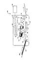
次に、いくつかの図を通じて、同じ数字が対応する部分をさす図面をさらに詳しく参照すると、図1は、定着システム102を組み込んだ電子写真式イメージング装置100の略側面図を示している。例示として、装置100はレーザプリンタを有する。しかしながら、装置100は、別法として、例えばコピー機、ファクシミリ機、または多機能周辺(MFP)装置を有する、定着システム使用の他の任意のイメージング装置を有することもあると理解されよう。
Referring now to the drawings in which like numerals refer to like parts throughout the several views, FIG. 1 shows a schematic side view of an
図1に示されるように、装置100は、光導電体ドラム106の表面を所定のレベルに帯電させるのに用いられる帯電ローラ104を有する。レーザ・ダイオード(図示されてない)は、レーザ・スキャナ108内に備えられていて、この光導電体ドラム106の表面の全域で掃引されるように変調されるレーザ・ビーム110を放射して、選択的に光導電体ドラムの表面の電荷を放電させる。図1に示される向きでは、光導電体ドラム106は、時計回りの方向に回転する。現像ローラ112は、選択的に光導電体ドラム106の表面の電荷を放電させた後で、この光導電体ドラムの表面上にある静電潜像を現像するために使用される。トナー114は、電子写真式印刷カートリッジ118のトナー・タンク116に入れられている。現像ローラ112は、トナー114を印刷カートリッジ118から現像ローラの表面に磁気的に引き寄せる内部磁石(図示されてない)を有する。現像ローラ112が回転すると(図1の時計回り)、トナー114は、現像ローラ112の表面に引き付けられ、次に、光導電体ドラム106の表面と現像ローラの表面との間のギャップを横切って転写されて、静電潜像を現像する。
As shown in FIG. 1, the
印刷媒体120、例えば用紙は、給紙ローラ(pickup roller)124によって、入力トレイ122から、装置100の搬送路に入れられる。各印刷媒体120は1枚1枚、装置100に通され、駆動ローラ126により搬送路に沿って移されて、各印刷媒体の前縁が、光導電体ドラム106の表面上の、静電潜像を有する領域の回転と同期化されるようにしている。光導電体ドラム106が回転すると、そのドラムの放電部位に付着されたトナーは、転写ローラ128が帯電させた印刷媒体120に接触して、この印刷媒体が、トナー微粒子を、光導電体ドラムの表面から離れて、この印刷媒体の表面上に引き付けるようにしている。通常、光導電体ドラム106の表面から印刷媒体120の表面へのトナー微粒子の転写は、まったく効率的であるとは限らない。それゆえ、一部のトナー微粒子は、光導電体ドラムの表面上に残っている。光導電体ドラム106が回転し続けると、このドラム表面に付着されたままになっているトナー微粒子は、クリーニング・ブレード130によって除去されて、トナー廃棄ホッパ(toner waste hopper)132に入れられる。
The
印刷媒体120が、搬送路に沿って、光導電体ドラム106を通り過ぎると、コンベヤー134は、この印刷媒体を定着システム102に受け渡す。印刷媒体120は、以下にさらに詳しく述べられる定着システム102の定着ローラ136と加圧ローラ138の間を通過する。加圧ローラ138が回転すると、定着ローラ136を回転させ、印刷媒体120が定着ローラ136と加圧ローラ138の間に引き込まれる。印刷媒体がローラ136とローラ138の間を通過すると、印刷媒体120に熱と押圧力が加えられ、それにより、トナーが、この印刷媒体の表面に定着する。最後に、出力ローラ140は、印刷媒体120を定着システム102から搬送して、印刷媒体120を出力トレイ142に受け渡す。
As the
図1で確認されるように、装置100は、フォーマッタ144とコントローラ146も有する。フォーマッタ144は、別々のホスト・コンピューティング装置148のアプリケーション・プログラムといっしょに動作するプリント・ドライバから、表示リスト、ベクター・グラフィックス、またはラスタ印刷データなどの印刷データを受け取る。フォーマッタ144は、この印刷データを、二値印刷データのストリームに変換して、そのデータをコントローラ146に送る。さらに、フォーマッタ144とコントローラ146は、電子写真式イメージング・プロセスを制御するのに必要なデータを交換する。特に、コントローラ146は、二値印刷データのストリームをレーザ・スキャナ108に供給する。レーザ・スキャナ108内のレーザ・ダイオードに送られた二値印刷データのストリームは、レーザ・ダイオードを変調して、光導電体ドラム106上に静電潜像を生成する。
装置 As can be seen in FIG. 1, the
コントローラ146は、二値印刷データのストリームをレーザ・スキャナ108に供給することだけでなく、帯電ローラ104、現像ローラ112、転写ローラ128を含め、装置100内で使用される構成要素に電圧および電流を供給する高圧電源(図示されてない)も制御する。さらに、コントローラ146は、印刷媒体120を、装置100の搬送路を通すのに必要な様々なクラッチおよび送りローラ(図示されてない)だけでなく、プリンタ歯車列(図示されてない)を駆動する駆動モータ(図示されてない)も制御する。
The
電力制御回路150は、定着システム102への電力の印加を制御する。装置100が、印刷ジョブまたはコピージョブの処理の開始を待っている間、定着システム102の温度を、待機モードに対応する待機温度に保つ。待機モードでは、電力消費を減らし、温度を下げ、システムの劣化を少なくするために、電力制御回路150は、下げたレベルで電力を定着システム102に供給する。
The
定着ジョブの処理が始まると、コントローラ146は、定着システム102への印刷媒体120の到達よりも充分前に、電力制御回路150により定着システム102に供給される電力を大きくして、その温度を定着温度まで高める。定着ジョブの完了後、コントローラ146は、定着システム102に供給される電力を待機モードに対応するレベルまで小さくするように電力制御回路150をセットする。定着システム102に供給される電力のサイクリングは、定着ジョブを受け取って処理するように装置100の動作の間、また装置がアイドル状態の間も、進行している。
When the fusing job begins, the
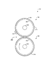
図2は、図1に示される定着システム102の詳細な端面図を示している。図2に示されるように、定着システム102は、共に間にニップ200を形成している定着ローラ136と加圧ローラ138を有する。さらに、定着システム102は、例えば定着ローラ136に結び付けられた温度センサ202を有することもある。
FIG. 2 shows a detailed end view of the
定着ローラ136は、通常、中空管204として形成される。例示として、中空管204は、アルミニウムまたは鋼などの金属から成り、その直径は、約45ミリメートル(mm)である。さらに他の例示として、中空管204の厚さは、約2.5mmである。定着ローラ136は、厚さが例えば約4mmである外層206を有する。以下にさらに詳しく述べられるように、外層206の外面210は、テクスチャ付きのパターンを備えており、そのパターンは、印刷媒体が定着システム102を通過するときに印刷媒体に定着したトナーに、同様な(鏡像)パターンを転写する。説明されるように、このようなパターンを備えることは、印刷媒体の全域に存在するかもしれないトナーの光沢差をマスクするのに役立つ。このテクスチャ付きのパターンは、どんな表面材料も備えることができるが、さらにローエンドの印刷装置に用いられるような比較的に弾性のないポリマ材料でできている外層206上に、そのテクスチャ付きのパターンを提供すれば、最大の利益が得られることが予想される。トナーが、外層206に付着しないようにするために、ポリテトラフルオロエチレン(PTFE)などの粘着しない材料できているコーティング(図2には見えない)を、その外層の外面210に付けることもある。このような粘着しないコーティングは、例えば、その厚さが約1.5〜2ミリメートルであることもある。このコーティングは、それほどに薄いので、外層206のテクスチャをふさぐ(occlude)ことはない。
The fixing
定着ローラ136内には、内部発熱体208が備えられており、この発熱体は、例示として、ハロゲン・ランプまたはニクロム発熱体を有する。内部発熱体208が図示されて、説明されているが、定着ローラ136は、別法として、外部熱源を備えか、あるいは、要望があれば熱源をまったく備えないこともあることに留意されたい。
The fixing
加圧ローラ138は、例えば、ポリマ材料でできている外層214を備えた中空金属管212を有することもある。定着ローラ136と同様に、加圧ローラ138も、PTFEなどの粘着しない材料できているコーティング(図2には見えない)を備えることがある。オプションとして、加圧ローラ138内に備えられるものは、内部発熱体216であり、この発熱体216は、例示として、ハロゲン・ランプまたはニクロム発熱体を有する。別法として、加圧ローラ138は、それ自体の熱源なしに構成されることもある。しかしながら、熱源を備えると、加圧ローラ138上にトナーが蓄積するのが妨げられることがある。
The
温度センサ202は、通常、サーミスタを含み、このサーミスタは、ニップ200の入口付近の位置において、定着ローラ136のすぐ近くに置かれるか、あるいは、定着ローラ136と接触している。このような配置は好ましいとはいえ、他の配置も可能であることが理解されよう。代替構成では、センサ202は、非接触形サーモパイル(図示されてない)を有することもある。非接触形サーモパイルは、信頼性の観点から好ましいが、このようなサーモパイルは、さらに高価のものであり、それゆえ、装置100のコストを増大させる。
The
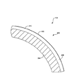
定着ローラ136は、図3と図4に、さらに詳しく示されている。図3に示されるように、定着ローラ136の外層206の外面210は、複数の反復した図形的要素302を有するテクスチャ付きパターン300(このパターンの一部だけが図3に示されているが、好ましくは、外面210全体に、テクスチャが付けられている)。所望の結果に応じて、反復した図形的要素302の種類を変えることができる。しかしながら、好ましくは、高頻度のパターンが得られるように、反復した図形的要素302は、小さく、例えば、その面積が約0.01〜10平方ミリメートルである。通常の当業者で理解されるように、面積のさらに小さいパターンは、つや消しの外観を作り出すことで、光沢差をより良くマスクすることもある。例示として、図3に示されるように、テクスチャ付きのパターン300は、蜂の巣形などの反復する幾何学的形状を有することもある。長方形、三角形、菱形、円形などを含め、他の幾何学的形状を使用することもある。
The fixing
代替実施形態では、テクスチャ付きのパターン300は、ペイズリー模様のような非対称の非幾何学的な模様を有する。一見、反復しない種類は、光沢差をマスクするのに、より優れているから、非対称のパターンは好ましいことがある。非対称のパターンの他の例は、模倣された筆致のパターンである。このようなパターンは、写真、素描、彩色画などのイメージを印刷するのに特に好ましいかもしれない。
In an alternative embodiment, the
図4に示されるように、定着ローラ136の外層206の外面210上に、複数の突出部400を形成すれば、テクスチャ付きのパターン300を作り出すことができる。しかしながら、別法として、外面210上に、複数の圧痕を形成しても、パターン300を作り出すことができる。とはいえ、いずれにしても、パターン300は、一般に知られている成形プロセス(例えば、射出成形)を通じて、作り出すことができる。
テ ク ス チ ャ As shown in FIG. 4, if a plurality of
動作しているときは、定着ローラ136も加圧ローラ138も、備えられた発熱体(例えば、内部発熱体208および216)によって加熱される。定着システム102を動作温度まで加熱すると、印刷媒体(例えば、紙)のトナー側が定着ローラ136に面し、それゆえ、テクスチャ付きのパターン300に面するように、その印刷媒体をニップ200に通すことができる。印刷媒体がニップ200を通過すると、トナーが、その印刷媒体に定着する。テクスチャ付きのパターン300が備えられているために、このパターンの鏡像を、定着したトナーに刻み込むか、あるいは、トナーに浮き上がらせて、目に見えるパターンをトナーに施す。上述のように、定着ローラが比較的に可撓性のないものである場合には、トナーに光沢差が現れることもある。しかしながら、トナーに転写されるパターンは、このような光沢差をマスクし、それゆえ、美しさの点でより好ましい結果をもたらす。特に、印刷媒体(例えば、出版物)を眺めて、光が反射して観察者の目に入るようにすると、観察者の目は、その転写されたパターンを、光沢差よりも容易に記録する。
During operation, both the fixing
定着システムの特定の実施形態と、その働きが、例証を目的として、上述の説明および図面で詳しく開示されてきたが、当業者であれば、その変更や変形は、併記の特許請求の範囲に述べられる本発明の範囲から逸脱することなく実行できることが理解されよう。 While specific embodiments of the fusing system and its operation have been disclosed in detail in the foregoing description and drawings for purposes of illustration, those skilled in the art will appreciate that modifications and variations are within the scope of the appended claims. It will be appreciated that the present invention can be practiced without departing from the scope thereof.
136 定着ローラ
138 加圧ローラ
136
Claims (10)
金属管と、
テクスチャ付きの外面を有する、前記金属管上に形成されたポリマ材料の層と、
を備えることを特徴とする定着ローラ。 In a fixing roller of an electrophotographic imaging apparatus,
Metal tubes,
A layer of polymeric material formed on the metal tube, having a textured outer surface;
A fixing roller comprising:
前記第1のローラの外面に係合する外面を有する第2のローラと、
を備えることを特徴とする定着システム。 A first roller consisting of a textured outer surface having a high frequency pattern of repeating graphical elements;
A second roller having an outer surface engaging the outer surface of the first roller;
A fixing system comprising:
トナーを印刷媒体に引き付けるステップと、
前記トナーを前記印刷媒体に定着させるステップと、
前記定着したトナーにテクスチャを付けて、光沢差をマスクするステップと、
を備えたことを特徴とする方法。
In a method of masking a gloss difference on a print medium,
Attracting toner to the print media;
Fixing the toner to the print medium;
Applying a texture to the fixed toner to mask a gloss difference;
A method comprising:
Applications Claiming Priority (1)
| Application Number | Priority Date | Filing Date | Title |
|---|---|---|---|
| US10/243,435 US6668152B1 (en) | 2002-09-13 | 2002-09-13 | Textured fuser roller and method for texturing toner |
Publications (2)
| Publication Number | Publication Date |
|---|---|
| JP2004110024A true JP2004110024A (en) | 2004-04-08 |
| JP2004110024A5 JP2004110024A5 (en) | 2005-05-26 |
Family
ID=29735578
Family Applications (1)
| Application Number | Title | Priority Date | Filing Date |
|---|---|---|---|
| JP2003318162A Pending JP2004110024A (en) | 2002-09-13 | 2003-09-10 | Fixing roller with texture and method for masking gloss difference on printing medium |
Country Status (2)
| Country | Link |
|---|---|
| US (1) | US6668152B1 (en) |
| JP (1) | JP2004110024A (en) |
Cited By (2)
| Publication number | Priority date | Publication date | Assignee | Title |
|---|---|---|---|---|
| JP2010015148A (en) * | 2008-06-30 | 2010-01-21 | Xerox Corp | Oil less fusing fixing using nano/micro textured fusing fixing surface |
| US7960084B2 (en) | 2006-10-26 | 2011-06-14 | Ricoh Company, Ltd. | Method of preparing information recording medium |
Families Citing this family (15)
| Publication number | Priority date | Publication date | Assignee | Title |
|---|---|---|---|---|
| WO2004028806A1 (en) * | 2002-09-27 | 2004-04-08 | Riso Kagaku Corporation | Light-curing ink fixing device, fixing method, and printer |
| US7231153B2 (en) * | 2005-01-13 | 2007-06-12 | Xerox Corporation | Systems and methods for monitoring replaceable units |
| US7403214B2 (en) * | 2006-02-21 | 2008-07-22 | Lexmark International, Inc. | Systems and methods for adjusting the dynamic range of a scanning laser beam |
| JP5119774B2 (en) * | 2007-07-11 | 2013-01-16 | コニカミノルタビジネステクノロジーズ株式会社 | Belt fixing device and image forming apparatus |
| CN101444874B (en) * | 2008-12-31 | 2011-06-08 | 东北轻合金有限责任公司 | Cold roll laser texturing method |
| US9062219B2 (en) * | 2009-01-21 | 2015-06-23 | Xerox Corporation | Superhydrophobic nano-fabrics and coatings |
| US9217968B2 (en) | 2009-01-21 | 2015-12-22 | Xerox Corporation | Fuser topcoats comprising superhydrophobic nano-fabric coatings |
| US9471019B2 (en) * | 2010-01-25 | 2016-10-18 | Xerox Corporation | Polymer-based long life fusers |
| US9329544B2 (en) * | 2010-01-25 | 2016-05-03 | Xerox Corporation | Polymer-based long life fusers and their methods of making |
| JP2012118516A (en) * | 2010-11-11 | 2012-06-21 | Konica Minolta Business Technologies Inc | Method for forming hologram image, toner for electrostatic charge image development and hologram image forming apparatus |
| US8852833B2 (en) | 2012-04-27 | 2014-10-07 | Xerox Corporation | Imaging member and method of making an imaging member |
| US9952539B2 (en) * | 2012-09-27 | 2018-04-24 | Electronics For Imaging, Inc. | Method and apparatus for variable gloss reduction |
| US10114307B2 (en) * | 2012-09-27 | 2018-10-30 | Electronics For Imaging, Inc. | Method and apparatus for variable gloss reduction |
| ES2702660T3 (en) | 2013-10-15 | 2019-03-04 | Electronics For Imaging Inc | Procedure and apparatus for variable brightness reduction |
| WO2022041035A1 (en) * | 2020-08-24 | 2022-03-03 | 江苏大学 | Roller surface laser disordered and uniform texturing processing method |
Family Cites Families (4)
| Publication number | Priority date | Publication date | Assignee | Title |
|---|---|---|---|---|
| US4363862A (en) * | 1980-04-28 | 1982-12-14 | Minnesota Mining & Manufacturing Co. | Pressure-fixing apparatus and method |
| JP2690630B2 (en) * | 1991-05-17 | 1997-12-10 | 株式会社日立製作所 | Electrophotographic fixing device and electrophotographic device |
| US5753348A (en) * | 1995-05-31 | 1998-05-19 | Canon Kabushiki Kaisha | Fluororesin tube-covered fixing roller, and image formation apparatus |
| JP3595671B2 (en) * | 1997-12-22 | 2004-12-02 | キヤノン株式会社 | Charging device, image forming apparatus and process cartridge |
-
2002
- 2002-09-13 US US10/243,435 patent/US6668152B1/en not_active Expired - Fee Related
-
2003
- 2003-09-10 JP JP2003318162A patent/JP2004110024A/en active Pending
Cited By (2)
| Publication number | Priority date | Publication date | Assignee | Title |
|---|---|---|---|---|
| US7960084B2 (en) | 2006-10-26 | 2011-06-14 | Ricoh Company, Ltd. | Method of preparing information recording medium |
| JP2010015148A (en) * | 2008-06-30 | 2010-01-21 | Xerox Corp | Oil less fusing fixing using nano/micro textured fusing fixing surface |
Also Published As
| Publication number | Publication date |
|---|---|
| US6668152B1 (en) | 2003-12-23 |
Similar Documents
| Publication | Publication Date | Title |
|---|---|---|
| JP2004110024A (en) | Fixing roller with texture and method for masking gloss difference on printing medium | |
| US20030077092A1 (en) | Image heating apparatus | |
| JP5831740B2 (en) | Fixing device and image forming apparatus | |
| US10012932B2 (en) | Image forming apparatus incorporating fixing device | |
| US5660750A (en) | Image heating apparatus with elastic heater | |
| US10394156B2 (en) | Image formation apparatus controlling charging voltage and development voltage | |
| JP2009103789A (en) | Image forming device, and cleaning method for heating rotor or pressurizing member | |
| JP2007101861A (en) | Fixing device | |
| JP6249836B2 (en) | Fixing device | |
| JP2006317492A (en) | Fixing separation plate, fixing device and image forming apparatus | |
| JP2011043683A (en) | Image forming apparatus and image forming method | |
| JP2005050693A (en) | Heating device and image forming device | |
| JP5071410B2 (en) | Fixing device and image forming apparatus having the same | |
| JP2000010425A (en) | Fixing device | |
| US20020011475A1 (en) | Fixing roller member and fixing apparatus | |
| US8879977B2 (en) | Image forming apparatus and image forming method | |
| JP3542408B2 (en) | Image forming device | |
| JP2005300915A (en) | Fixing apparatus | |
| JP6816635B2 (en) | Peeling member, fixing device, and image forming device | |
| JP5493437B2 (en) | A heating roller, a fixing device, an image forming apparatus, and a heating roller manufacturing method. | |
| JP7247708B2 (en) | CLEANING DEVICE, IMAGE FORMING APPARATUS, AND CLEANING METHOD | |
| JP2009025405A (en) | Fixing method and image forming apparatus | |
| JP2006126847A (en) | Fusing assembly having temperature-equalizing device | |
| JP2000056597A (en) | Fixing device and image forming device | |
| JP2022168613A (en) | Image forming apparatus |
Legal Events
| Date | Code | Title | Description |
|---|---|---|---|
| A521 | Written amendment |
Free format text: JAPANESE INTERMEDIATE CODE: A523 Effective date: 20041005 |
|
| A621 | Written request for application examination |
Free format text: JAPANESE INTERMEDIATE CODE: A621 Effective date: 20041005 |
|
| A977 | Report on retrieval |
Free format text: JAPANESE INTERMEDIATE CODE: A971007 Effective date: 20070606 |
|
| A131 | Notification of reasons for refusal |
Free format text: JAPANESE INTERMEDIATE CODE: A131 Effective date: 20070612 |
|
| A521 | Written amendment |
Free format text: JAPANESE INTERMEDIATE CODE: A523 Effective date: 20070830 |
|
| A02 | Decision of refusal |
Free format text: JAPANESE INTERMEDIATE CODE: A02 Effective date: 20071030 |