JP2004102403A - Optical information reading device - Google Patents
Optical information reading device Download PDFInfo
- Publication number
- JP2004102403A JP2004102403A JP2002259972A JP2002259972A JP2004102403A JP 2004102403 A JP2004102403 A JP 2004102403A JP 2002259972 A JP2002259972 A JP 2002259972A JP 2002259972 A JP2002259972 A JP 2002259972A JP 2004102403 A JP2004102403 A JP 2004102403A
- Authority
- JP
- Japan
- Prior art keywords
- optical information
- reader
- pda
- terminal
- portable information
- Prior art date
- Legal status (The legal status is an assumption and is not a legal conclusion. Google has not performed a legal analysis and makes no representation as to the accuracy of the status listed.)
- Pending
Links
- 230000003287 optical effect Effects 0.000 title claims abstract description 100
- 238000004891 communication Methods 0.000 claims abstract description 43
- 238000012545 processing Methods 0.000 claims abstract description 12
- 229920001690 polydopamine Polymers 0.000 description 111
- 230000006870 function Effects 0.000 description 13
- 230000010365 information processing Effects 0.000 description 9
- 230000005540 biological transmission Effects 0.000 description 6
- 238000000034 method Methods 0.000 description 5
- 238000010586 diagram Methods 0.000 description 3
- 238000005286 illumination Methods 0.000 description 3
- 238000012360 testing method Methods 0.000 description 3
- 238000006243 chemical reaction Methods 0.000 description 2
- 230000008878 coupling Effects 0.000 description 2
- 238000010168 coupling process Methods 0.000 description 2
- 238000005859 coupling reaction Methods 0.000 description 2
- 238000003384 imaging method Methods 0.000 description 2
- 230000002093 peripheral effect Effects 0.000 description 2
- 230000002265 prevention Effects 0.000 description 2
- 230000007423 decrease Effects 0.000 description 1
- 238000011161 development Methods 0.000 description 1
- 208000030770 patent ductus arteriosus 3 Diseases 0.000 description 1
- 230000000452 restraining effect Effects 0.000 description 1
- 239000000126 substance Substances 0.000 description 1
- 238000003079 width control Methods 0.000 description 1
Images

Landscapes
- Power Sources (AREA)
Abstract
Description
【0001】
【発明の属する技術分野】
本発明は、バーコードや二次元コード等の光学情報を読取り、情報の処理を行うことが可能な携帯型の光学情報読取装置に関する。
【0002】
【発明が解決しようとする課題】
近年、携帯型のバーコードリーダ等の光学情報読取器に、読取ったデータの収集や処理等の機能を付加した、バーコードハンディターミナル(BHT)と称される装置が供されてきている。また、この種の光学情報読取器においては、把持部(ガングリップ)を有したハンドヘルド型(ガンタイプ)のものが、操作性の面で好まれるようになってきている。
【0003】
そこで、この種の光学情報読取装置の第1の従来例として、特開平11−328121号公報には、PDAのケース内にバーコード読取ユニットを一体的に組込んでBHTを構成すると共に、ガングリップを取付けたものが示されている。また、第2の従来例として、特開平10−269339号公報には、BHTにグリップ部を着脱可能に取付けるようにした構成のものが示されている。
【0004】
しかしながら、上記第2の従来例にあっては、PDAにバーコードリーダの機能を組込むため、開発コスト,製品コストの高いものとり、また、ユーザがバーコードリーダの機能を使用せずに、PDA単体として使用したい場合に、大型で取扱いに不便なものとなる欠点があった。そして、上記した第1及び第2の従来例では、BHTとグリップ部とを取外した場合に、グリップ部の使途がなかった。
【0005】
本発明は上記事情に鑑みてなされたもので、その目的は、光学情報の読取り及びそのデータの処理等を可能とした装置であって、携帯情報端末器及び光学情報読取器としてそれぞれが単独で使用でき、安価で、且つ、操作性,取扱い性に優れ、しかも全体としての稼働時間を長くすることができる光学情報読取装置を提供するにある。
【0006】
【課題を解決するための手段】
本発明者らは、小型で光学情報の読取り操作性に優れたハンドヘルド型の光学情報読取器(ガンスキャナ)と、小型,安価でありながら機能面に優れる(豊富なソフトウエアや周辺機器を利用できる)市販のPDA等の携帯情報端末器とを着脱自在に組合せる構成とすることにより、各々を単体として使用できることは勿論、組合せて使用することを着想した。この場合、光学情報読取器と携帯情報端末器との間での交信を行う交信手段を設け、光学情報読取器の読取りデータをその交信手段によって携帯情報端末器に送信することにより、いわゆるハンディターミナルとしての機能を実現することができ、全体として使いやすく安価な装置とすることができることを確認した。
【0007】
ここで、上記した光学情報読取器及び携帯情報端末器は、各々を単独で動作可能とする電池(充電可能な二次電池)を電源として内蔵することが一般的である。このため、上記のように両者を組合せていわゆるハンディターミナルとして使用する場合、一方の機器の電池の残容量がなくなると、他方の機器の電池に余力があっても、それ以上使用できなくなり、全体としての稼働時間(連続使用時間)が短く抑えられてしまう虞が考えられる。
【0008】
本発明の請求項1の光学情報読取装置は、ハンドヘルド型の光学情報読取器と、それに結合可能な携帯情報端末器と、それらの間でデータの送受信を行う交信手段とを具備し、光学情報読取器と携帯情報端末器との間で、相互に各々を駆動する電池からの動作電力の供給を可能とする電源接続手段を設けたところに特徴を有する。
【0009】
これによれば、光学情報読取器と携帯情報端末器とを結合することにより、それらを組合せたいわゆるハンディターミナルとして使用することができ、この場合、光学情報読取器の読取りデータを交信手段を介して携帯情報端末器に入力して所定の処理等を行うことができる。光学情報読取器は、ハンドヘルド型なので、組合せたものについても光学情報の読取りの操作性に優れたものとなる。光学情報読取器と携帯情報端末器とを分離した状態で、光学情報読取器を単独で使用することもできる。一方、携帯情報端末器についても、分離した状態は勿論、光学情報読取器と結合した状態であっても、単独での使用が可能である。
【0010】
この場合、光学情報読取器自体を安価に済ませることができることは勿論、携帯情報端末器についても、市販のPDA等を使用することができ、やはり安価に済ませることができ、ひいては全体としても安価に構成することができるのである。ちなみに、現在のBHTの価格は、10〜20万円程度であるのに対し、市販のPDAや光学情報読取器(バーコードリーダ)の価格は、共に3〜5万円程度であり、市販のPDAを用いれば、価格面での大幅なメリットを得ることができる。
【0011】
そして、電源接続手段を設けたことにより、光学情報読取器と携帯情報端末器とを結合した状態で、光学情報読取器から携帯情報端末器に動作電力を供給したり、逆に携帯情報端末器から光学情報読取器に動作電力を供給することができるので、一方の電池の残容量が少なくなった場合でも、他方の電池から必要な動作電力を受けることができ、この結果、全体としての稼働時間を長くすることができる。
【0012】
このとき、電源接続手段に、光学情報読取器から携帯情報端末器に供給する電力を該携帯情報端末器の動作に適した電圧に調整する出力電圧調整部と、携帯情報端末器から光学情報読取器に供給する電力を該光学情報読取器の動作に適した電圧に調整する入力電圧調整部とからなる電圧変換器を設けることができる(請求項2の発明)。これにより、光学情報読取器と携帯情報端末器との間で駆動電圧が異なっていても相互間での安定した動作電力の供給が可能となり、光学情報読取器と例えば市販の各種のPDAとの組合せが可能となり、ひいては機能等の異なる複数種類の装置を容易に構成することができる。
【0013】
また、光学情報読取器と携帯情報端末器との結合を、受台を介して行うように構成すると共に、上記電圧変換器を、その受台に組込むようにすることができる(請求項3の発明)。これによれば、光学情報読取器と携帯情報端末器との結合を、受台を介して行うことにより、両者の結合の確実化や結合作業の容易化等を図ることができる。しかも、電圧変換器をその受台に組込むことにより、光学情報読取器あるいは携帯情報端末器に、電圧変換器を付加することなく済ませることができ、既存のものを使用することができる。
【0014】
あるいは、電圧変換器を、光学情報読取器に設けたり(請求項4の発明)、電圧変換器のうち出力電圧調整部を携帯情報端末器に設けると共に入力電圧調整部を光学情報読取器に設けたり(請求項6の発明)することができる。いずれも、光学情報読取器と携帯情報端末器との間に中間介在物を設けずに済ませることができる。電圧変換器を光学情報読取器に設ける際には、取外し可能に構成すれば(請求項5の発明)、光学情報読取器を単独で使用する場合に、よりコンパクトとすることができる。
【0015】
そして、光学情報読取器に、携帯情報端末器の動作可能時間を判定する判定手段を設けると共に、この判定手段により判定された該携帯情報端末器の動作可能時間と、自らの電池の残容量から推定される自身の動作可能時間とを比較することに基づいて、動作可能時間が長い側から短い側に対して電力供給を行うように制御する電力供給制御手段を設けることができる(請求項7の発明)。これによれば、光学情報読取器側が主体となって、光学情報読取器と携帯情報端末器との間での動作電力の供給,受給を合理的に行うことができ、ハンディターミナル全体としての稼働時間を十分に長くすることが可能となる。
【0016】
より具体的には、上記判定手段を、交信手段を介して携帯情報端末器から電池の残容量情報を受信することに基づいて携帯情報端末器の動作可能時間を推定するように構成することができ(請求項8の発明)、これにより、携帯情報端末器の動作可能時間を確実に判定することができる。さらにこの場合、判定手段が携帯情報端末器から電池の残容量情報を受信する時間間隔を、判定される携帯情報端末器の動作可能時間が短くなったときに、小さくなるように構成すれば(請求項9の発明)、携帯情報端末器の電池の残容量が少なくなってきたときに、よりこまめに動作電力の供給の制御が行われるようになり、全体としての稼働時間をより一層長くすることができる。
【0017】
ところで、機器としての性格上、携帯情報端末器はできるだけ小型の電池を採用したい事情があるのに対し、光学情報読取器は電池を収容するスペースに比較的余裕がある。そこで、光学情報読取器の電池を、携帯情報端末器の電池よりも動作可能時間が長くなるような容量のものとすることが(請求項10の発明)、合理的であり、また、上記のように動作可能時間が長い側が制御(電力供給の判断)を行う主体となることにより、全体としての稼働時間を長くするためにより効果的となる。
【0018】
【発明の実施の形態】
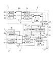
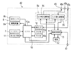
以下、本発明の一実施例について、図1ないし図4を参照しながら説明する。図1は、本実施例に係る光学情報読取装置1の外観を示し、図2は、この光学情報読取装置1の電気的構成を概略的に示している。
【0019】
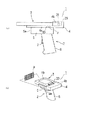
この光学情報読取装置1は、光学情報読取器たるハンドヘルド型のバーコードリーダ2(ガンスキャナ)と、携帯情報端末器たる市販のPDA3と、このPDA3を載置状に保持すると共に前記バーコードリーダ2に結合させる受台4とを分離可能に組合せて構成され、その組合せ状態で、バーコードの読取り及び読取ったデータの処理,収集等を行うことが可能な、いわゆるバーコードハンディターミナル(BHT)として機能するようになっている。
【0020】
そのうち、まず、バーコードリーダ2は、前後方向(図1で左右方向)にやや長い矩形箱状をなす本体部5の下面側に、その後部側から下方やや斜め後方に延びる把持部(ガングリップ)6を一体的に有して構成されている。前記把持部6の前面上部側には、読取用のキーであるトリガキー7が設けられている。また、前記本体部5の前面部には読取窓5aが設けられ、内部には読取手段たる画像読取部8が設けられている。図2に一部のみ示すように、この画像読取部8は、光学情報たるバーコードB(図1(b)参照)に対して横方向に延びる細長い照明光を照射する照明光源8a、バーコードBからの反射光を撮像するためのCCDセンサ等からなる受光センサ8b、結像レンズ等の光学系を備える周知構成とされている。
【0021】
また、前記本体部5の上面部には、後述する受台4を着脱可能に結合するための嵌合部(図示せず)が設けられていると共に、交信手段の一部を構成する有線通信用のコネクタ9(図1(a)参照)が設けられている。尚、このバーコードリーダ2は、図1(b)に示すように、離れた位置(例えば30mm以上)のバーコードBの読取りが可能とされ、また、その際の読取範囲が光表示されるようになっている。
【0022】
図2に示すように、このバーコードリーダ2内には、全体の制御を行う制御手段として機能する制御部10が設けられている。この制御部10は、CPU10a,ROM10b,RAM10c等を有するマイコンを主体として構成され、前記画像読取部8の照明光源8aの通電制御を行うと共に、受光センサ8bからの信号が入力されるようになっている。また、この制御部10(CPU10a)には、前記トリガキー7の信号が入力されるようになっていると共に、表示出力部11の表示を制御するようになっている。
【0023】
そして、このバーコードリーダ2内には、二次電池からなる電池12が設けられており、前記制御部10(CPU10a)により制御される電源制御部13を介して各部に動作用の電源を供給するようになっている。この制御部10には、前記コネクタ9を介して前記PDA3との間で有線通信にてデータの送受信を行う交信手段たる通信I/F14が接続され、前記画像読取部8により読取ったデータが前記PDA3に出力されるようになっている。
【0024】
このとき、前記コネクタ9には、前記電源制御部13に接続され電源接続手段の一部を構成する電源出力端子9a及び電源入力端子9bが設けられている。これにて、後述するように、本実施例では、前記PDA3との間で動作電力を授受(電池12からの電力供給及び受給)することが可能とされるようになっている。また、コネクタ9には、前記通信I/F14に接続され交信手段を構成する信号端子9cも設けられている。つまり、1個のコネクタ9が通信用(信号用)及び電源用に共用されるようになっている。
【0025】
さらに、このバーコードリーダ2には、例えばパソコン等の外部の情報処理装置15(図3にのみ図示)との間で交信するための外部有線通信手段として機能すると共に、ACアダプタ16(図3にのみ図示)を介して外部から駆動(あるいは充電)用の電力供給を受けるための接続ケーブルI/F(図2に外部電源入力端子17のみ図示)が設けられている。この接続ケーブルI/Fは、図示はしないが、前記把持部6の下端部に図示しないコネクタを有しており、図3に示すように、ケーブル18を介して外部の情報処理装置15(及びACアダプタ16)と接続されるようになっている。
【0026】
一方、前記PDA3は、全体として薄形の矩形状をなし、その表面(正面)には、例えばLCDからなる表示部19が設けられていると共に、その表示部19の表面のタッチパネルやその下側に位置する複数の操作キーからなる操作部20が設けられている。また、図1(a)に示すように、PDA3の下面部には、前記バーコードリーダ2と交信を行うための交信手段の一部を構成する有線通信用のコネクタ21が設けられている。尚、このPDA3としては、市販の各種のPDAから用途等に適したものを選んで用いることができる。
【0027】
図2に示すように、このPDA3内には、CPU22a,ROM22b,RAM22c等を有するマイコンを主体として構成され、全体の制御や各種のデータ処理を行うための制御部22が設けられている。この制御部22(CPU22a)は、前記表示部19の表示制御を行うと共に、前記操作部20の操作信号が入力されるようになっている。また、この制御部22(CPU22a)には、補助メモリ23が接続されている。
【0028】
さらに、前記制御部22には、前記バーコードリーダ2から出力されたデータを前記コネクタ21を介して入力するための交信手段を構成する通信I/F24が接続されている。このとき、コネクタ21には、信号端子21cが設けられている。これにて、PDA3は、入力されたデータの各種の処理、記憶、表示、外部へのデータ出力等を行うようになっている。
【0029】
そして、このPDA3内には、二次電池からなる電池26が設けられており、前記制御部22により制御される電源制御部27を介して各部に動作用の電源を供給するようになっている。このとき、本実施例では、後述するように、前記バーコードリーダ2との間で動作電力を授受することが可能とされており、前記コネクタ21には、前記電源制御部27に接続され電源接続手段の一部を構成する電源入力端子21a及び電源出力端子21bが設けられている。従って、前記コネクタ21が電源用及び通信用(信号用)に共用されるようになっている。
【0030】
さらに、図3に示すように、このPDA3は、前記コネクタ21にケーブル25が接続されることにより、外部の情報処理装置15及びACアダプタ28と接続可能とされている。これにて、外部の情報処理装置15との間でのデータのやり取りや、ACアダプタ28を介して外部から駆動(あるいは充電)用の電力供給を受けることが可能とされている。尚、このPDA3の外部の情報処理装置15及びACアダプタ28との接続は、単独、あるいは受台4に保持された状態のどちらでも可能とされている。
【0031】
これに対し、前記受台4は、次のように構成されている。即ち、この受台4は、図1に示すように、前記PDA3が載置される載置板部4aの基端側(図1で右端側)に、受容部4bを有すると共に、先端側に、脱落防止部(図示せず)を有して構成される。前記載置板部4aは、前記PDA3のうち上端側部分を除く部位を受支える大きさの平板状をなし、前記受容部4bは、載置板部4aの上面側に、前記PDA3の下部が差込まれることにより、該PDA3の下部の正面及び背面、左右の側面及び下面を受けて拘束するポケット状に構成されている。
【0032】
図示はしないが、前記脱落防止部は、前記載置板部4aに対して回動可能に取付けられ、受容部4bに差込まれたPDA3の上部を係止して脱落を防止する係止位置と、その係止を解いてPDA3の下部の受容部4bに対する差込み及び抜出しを自在とする解放位置との間を移動させることができるようになっている。これにて、PDA3は、受台4に着脱可能に保持されるようになっており、その保持状態では、前記表示部19及び操作部20が露出するようなっている。
【0033】
また、前記脱落防止部は、前記載置板部4aの下面側に一杯に回動させた状態で、受台4ひいてはPDA3を水平な台上に斜めに立てるための支持脚として機能するようになっている。そして、図1(a)に示すように、前記受容部4bの奥部(内部)には、第1のコネクタ29が設けられており、PDA3の下部を受容部4bに差込んだ状態で、PDA3のコネクタ21がその第1のコネクタ29に差込み接続されるようになっている。
【0034】
さらに、この受台4(載置板部4a)の下面部には、図1(a)に示すように、第2のコネクタ30が設けられていると共に、前記バーコードリーダ2の本体部5の上面の嵌合部と嵌合する図示しない被嵌合部が設けられている。これにて、例えば前後方向へのスライドによりそれら嵌合部と被嵌合部とが嵌合することによって、バーコードリーダ2と受台4(PDA3)とが着脱可能に結合されるようになっている。このとき、図1(a)に示すように、受台4の第2のコネクタ30が、バーコードリーダ2のコネクタ9に差込み接続されるようになっている。
【0035】
さて、この受台4は、図2に示すように、上記第1のコネクタ29及び第2のコネクタ30間を接続する電源線31,32及び信号線33を備えている。これにて、バーコードリーダ2とPDA3との結合状態では、信号線33により、バーコードリーダ2の信号端子9c(通信I/F14)と、PDA3の信号端子21c(通信I/F24)とが接続され、以て、それらの間での交信が可能とされる(交信手段が構成される)ようになっている。尚、信号線33に、入出力信号を変換する信号変換回路を挿設しても良く、これにより、バーコードリーダ2とPDA3との間で通信仕様(プロトコル)が異なっていてもそれらの間の交信が可能となる。
【0036】
これと共に、前記電源線31により、バーコードリーダ2の電源出力端子9aとPDA3の電源入力端子21aとが接続され、前記電源線32によりバーコードリーダ2の電源入力端子9bとPDA3の電源出力端子21bとが接続される。これにて、電源接続手段が構成され、受台4を介してバーコードリーダ2とPDA3との間で相互に各電池12,26から動作電力の供給を行うことができるようになっているのである。尚、バーコードリーダ2の電池12は、PDA3の電池26よりも動作可能時間が長くなるような容量のものとされている。
【0037】
このとき、本実施例では、前記受台4内には、電圧変換器34が組込まれている。この電圧変換器34は、前記電源線31に挿設され、前記バーコードリーダ2からPDA3に供給する電力を該PDA3の動作に適した電圧に調整する出力電圧調整部35と、電源線32に挿設され、前記PDA3からバーコードリーダ2に供給する電力を該バーコードリーダ2の動作に適した電圧に調整する入力電圧調整部36とから構成される。詳しい説明は省略するが、これら出力電圧調整部35及び入力電圧調整部36は、共に周知のDC−DCコンバータ(スイッチングレギュレータ)からなり、PWM(パルス幅制御)方式により、入力された直流電圧を所定電圧に変換して出力するように構成されている。
【0038】
この電圧変換器34は、バーコードリーダ2の制御部10(CPU10a)により制御されるようになっている。このとき、後の作用説明でも述べるように、バーコードリーダ2の制御部10は、そのソフトウエア的構成(制御プログラムの実行)により、PDA3の結合状態で、上記した通信I/F14,通信I/F24等の交信手段を介して、該PDA3から電源情報(電池26の残容量情報や動作電圧情報)を受信するようになっている。
【0039】
そして、制御部10は、その電池26の残容量情報から、PDA3の残り動作可能時間t1を判定(推定)すると共に、その動作可能時間t1と、自己の電池12の残容量から推定される自身の残り動作可能時間t2とを比較し、残り動作可能時間が長い側から短い側に対して電力供給を行うように制御するようになっている。従って、制御部10が、判定手段及び電力供給制御手段として機能するようになっているのである。また、制御部10は、前記PDA3の動作電圧情報から、出力電圧調整部35及び入力電圧調整部36の駆動パルス幅を決定するようになっている。
【0040】
この場合、上記電源情報を受信するにあたっては、バーコードリーダ2の制御部10は、電源情報要求信号を所定の時間間隔で送信するようになっている。従って、PDA3の制御部22は、そのソフトウエア的構成(制御プログラムの実行)により、電源情報要求信号を受信すると、電源情報を送信するようになっているのである。更に、本実施例では、制御部10は、前記電源情報要求信号を送信する時間間隔ひいては電源情報を受信する時間間隔を、PDA3の電池26の残容量の大小に応じて変更するようになっている。
【0041】
具体的には、制御部10には、PDA3の電池26の残容量Eに対し、送信時間間隔を決定するための2個のしきい値V1,V2が予め設定されている。そのうち、しきい値V1は、満充電に近い値に設定され、しきい値V2は、例えば残り動作可能時間が1時間程度となる残容量に設定される。そして、残容量Eがしきい値V1以下で且つしきい値V2以上であるときには、要求信号の送信時間間隔が標準的な時間(例えば20分)とされ、残容量Eがしきい値V1を越えているときには、それより大きい送信時間間隔(例えば30分)とされ、残容量Eがしきい値V2未満となったときには、小さい送信時間間隔(例えば5分)とされるのである。
【0042】
尚、本実施例では、前記バーコードリーダ2がPDA3の結合を検出する結合検出手段が、例えば次のように構成されている。即ち、バーコードリーダ2の制御部10は、電源ON時において、前記通信I/F14からテスト信号を送信するように構成され、一方、PDA3の制御部22は、やはりそのソフトウエア的構成により、前記テスト信号を受信すると、所定の返信信号を通信I/F24から送信するようになっている。そして、バーコードリーダ2の制御部10は、テスト信号を送信してから一定時間以内に、返信信号を受信したときに、PDA3が結合されていると判断するように構成されている。
【0043】
また、本発明の要旨とは直接的には関係ないので、詳しい説明は省略するが、バーコードリーダ2は、ACアダプタ16を介して外部電源に接続されているときには、外部電源から電力供給を受けることができ、電池12の充電も行うようになっている。そして、外部電源が接続されており、且つPDA3が結合されているときには、外部電源から供給される電力の一部をPDA3に出力するようになっている。さらに、PDA3は、バーコードリーダ2と分離されている状態で、ACアダプタ28を介して外部電源に接続されているときには、外部電源から電力供給を受けることができ、電池26の充電も行うようになっている。
【0044】
次に、上記構成の作用について、図3及び図4も参照して述べる。上記構成においては、上述のように、PDA3を受台4に結合し(保持させ)、受台4をバーコードリーダ2に結合することにより、光学情報読取装置1を構成することができる。この際、バーコードリーダ2とPDA3との結合を、受台4を介して行う構成としたことにより、両者の結合の確実化や結合作業の容易化を図ることができる。
【0045】
しかも、受台4の受容部4bに対するPDA3の差込みにより、第1のコネクタ29とコネクタ21とがいわば自動的に接続され、また、バーコードリーダ2に対する受台4の嵌合により、第2のコネクタ30とコネクタ9とがいわば自動的に接続されるというように、機械的結合だけでなく、電気的な接続も同時に行われるので、それらコネクタ間の結合作業を別途に行う必要もない。このとき、各コネクタの接続により、信号系及び電源系の双方の接続が一括して行われるので、接続構造が簡単となり、取扱い性が良好となって接続作業の簡単化を図ることができる。
【0046】
この光学情報読取装置1は、バーコードリーダ2上にPDA3が受台4を介して載置された如き状態に連結されると共に、図2に示すように、通信I/F14,コネクタ9(信号端子9c),第2のコネクタ30,信号線33,第1のコネクタ29,コネクタ21(信号端子21c),通信I/F24からなる交信手段により、バーコードリーダ2とPDA3との間のデータ通信が可能に接続され、いわゆるバーコードハンディターミナルとして構成される。
【0047】
これにより、図1(b)に示すように、光学情報読取装置1のバーコードリーダ2によりバーコードBを読取り、その読取りデータをPDA3に送信して処理,蓄積等を行うことができる。尚、この読取り時には、ユーザは、バーコードリーダ2の把持部6を握って操作すれば良く、操作しやすいものとなり、また、離れた位置のバーコードBの読取りも容易となる。
【0048】
さて、光学情報読取装置1を構成するバーコードリーダ2及びPDA3は、基本的には、夫々が内蔵する電池12及び26を電源として駆動されるようになる。このとき、バーコードリーダ2とPDA3とを組合せていわゆるハンディターミナルとして使用する場合、いずれか一方の電池12,26の残容量がなくなると、装置として使用できなくなる虞が考えられる。そこで、本実施例では、バーコードリーダ2のコネクタ9の電源出力端子9a及び電源入力端子9b、受台4のコネクタ29,30並びに電源線31,32、PDA3のコネクタ21の電源入力端子21a及び電源出力端子21bからなる電源接続手段を設けたことにより、バーコードリーダ2とPDA3と相互間において動作電力の供給(融通)が可能となるのである。
【0049】
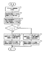
図4のフローチャートは、バーコードリーダ2の制御部10(CPU10a)が実行する、バーコードリーダ2とPDA3との間で電力供給を行う場合の処理手順を示している。即ち、まずステップS1では、交信手段によりPDA3から電源情報を受信することが行われる。この電源情報には、電池26の残容量Eの情報やPDA3の動作電圧の情報が含まれる。また、この電源情報の受信は、上記したような所定の時間間隔で行われる。ステップS2では、電源情報のうち動作電圧情報から、電圧変換器34(出力電圧調整部35及び入力電圧調整部36)のPWM制御の駆動パルス幅の決定が行われる。
【0050】
次のステップS3では、PDA3の電池26の残容量Eの情報から、PDA3の残り動作可能時間t1が求められ、その動作可能時間t1と自身の残り動作可能時間t2とを比較することが行われる。PDA3の動作可能時間t1がバーコードリーダ2の動作可能時間t2以下の場合には(ステップS4にてNo)、ステップS5にて、時間t1とt2との差に応じた送電量を求めて、出力電圧調整部35を駆動する(PDA3に対して動作電力を供給する)時間を算出することが行われる。そして、ステップS6にて、算出した時間だけ、出力電圧調整部35を駆動する信号を出力することが行われる。このとき、上記ステップS2にて求められたPWM制御の駆動パルス幅にて出力電圧調整部35が駆動されることは勿論である。
【0051】
一方、PDA3の動作可能時間t1がバーコードリーダ2の動作可能時間t2よりも大きい場合には(ステップS4にてYes)、ステップS7にて、時間t1とt2との差に応じた送電量を求めて、入力電圧調整部36を駆動する(PDA3から動作電力を受給する)時間を算出することが行われる。そして、ステップS8にて、同様に、算出した時間だけ、入力電圧調整部36を駆動する信号を出力することが行われるのである。
【0052】
これにて、バーコードリーダ2とPDA3とを結合してハンディターミナルとして使用している場合に、バーコードリーダ2の電池12及びPDA3の電池26の一方の残容量が少なくなった場合でも、他方から必要な動作電源を供給することができ、全体として継続して使用できる時間を長くすることができる。また、このとき、受台4に電圧変換器34を設けたことにより、バーコードリーダ2とPDA3との間で駆動電圧が異なっていても、安定した動作電力の供給が可能となるのである。
【0053】
さらに、上記したフローチャートには記載しなかったが、本実施例では、バーコードリーダ2がPDA3から電源情報を受信する時間間隔を、電池26の残容量Eに応じて残容量Eが少なくなるほど時間間隔が短くなるように変更するようにしたので、PDA3の電池26の残容量Eが少なくなってきたときに、よりこまめに動作電力の供給の制御が行われるようになり、全体としての稼働時間をより一層長くすることができるのである。
【0054】
尚、図3に示すように、本実施例に係る光学情報読取装置1は、バーコードリーダ2とPDA3との結合状態で、外部の情報処理装置15(及び外部電源)に接続して使用することができる。また、バーコードリーダ2とPDA3とを分離して、各々を単独で使用することも可能であり、この場合にも、バーコードリーダ2を外部情報処理装置15(及び外部電源)に接続して使用したり、PDA3についても、単独であるいは受台4に保持された状態で、外部情報処理装置15(及び外部電源)に接続して使用することが可能である。
【0055】
このように本実施例によれば、小型でバーコードBの読取り操作性に優れたハンドヘルド型のバーコードリーダ2と、小型,安価でありながら機能面に優れる(豊富なソフトウエアや周辺機器を利用できる)市販のPDA3とを着脱自在に組合せる構成とすることにより、各々を単体として使用できることは勿論、それらを組合せて、バーコードBの読取り及びそのデータの処理等を可能としたいわゆるハンディターミナルとして使用することができる。特に本実施例では、バーコードリーダ2とPDA3との結合を受台4を介して行う構成としたので、両者の結合の確実化や結合作業の容易化等を図ることができる。
【0056】
この場合、バーコードリーダ2とPDA3とを結合して使用する場合にあっても、それらを分離して各々を単独で使用する場合にあっても、取扱い性、操作性に優れたものとなる。また、バーコードリーダ2自体を安価に済ませることができることは勿論、受台4についてもさほどコストのかからないものとなり、さらには、市販のPDA3を使用することができるので、全体として安価な装置として構成することができるものである。
【0057】
そして、電源接続手段を設けたことにより、バーコードリーダ2とPDA3とを結合した状態で、バーコードリーダ2からPDA3に動作電力を供給したり、逆にPDA3からバーコードリーダ2に動作電力を供給することができるので、一方の電池12,26の残容量が少なくなった場合でも、他方の電池26,12から必要な動作電力を受けることができ、この結果、全体としての稼働時間を長くすることができるものである。
【0058】
このとき、本実施例では、電圧変換器34を設けたことにより、バーコードリーダ2とPDA3との間で駆動電圧が異なっていても相互間での動作電力の供給が可能となり、バーコードリーダ2と例えば市販の各種のPDA3との組合せが可能となり、ひいては機能等の異なる複数種類の装置を容易に構成することができる。しかも、電圧変換器34を受台4に組込んだことにより、バーコードリーダ2あるいはPDA3自体に、電圧変換器34を付加することなく済ませることができ、既存のものを使用できるといったメリットも得ることができる。
【0059】
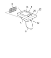
図5及び図6は、本発明の他の実施例に係る光学情報読取装置41の構成を示しており、上記実施例における光学情報読取装置1と異なる点は、光学情報読取器たるハンドヘルド型のバーコードリーダ42と、携帯情報端末器たるPDA3とを、受台を介さずに直接的に結合するように構成すると共に、前記バーコードリーダ42に電圧変換器34を設けるようにした構成にある。この場合、前記PDA3や、バーコードリーダ42の大部分の構成については、上記実施例と同等の構成であるため、以下、それら共通する部分については、詳細な説明(並びに図示)を省略し、符号も共通して使用することとする。
【0060】
図5に示すように、本実施例では、バーコードリーダ42の本体部5の上面に、PDA3が直接的に載置された形態に結合されるようになっている。このとき、図示はしないが、バーコードリーダ42の本体部5の上面側には嵌合部が設けられ、PDA3の下面側には、前記嵌合部に対して例えばスライドにより着脱可能に嵌合する被嵌合部が設けられる。
【0061】
これと共に、バーコードリーダ42及びPDA3には、それらの結合状態で両者の電気的接続を行うためのコネクタ43及び21が夫々設けられている。図6に示すように、そのうちバーコードリーダ42のコネクタ43には、電源出力端子43a、電源入力端子43b、信号端子43cが設けられている。コネクタ43,21の接続状態では、電源出力端子43aとPDA3の電源入力端子21aとが接続され、電源入力端子43bとPDA3の電源出力端子21bとが接続され、信号端子43cとPDA3の信号端子21cとが接続され、もって電源接続手段及び交信手段が構成されようになっている。
【0062】
そして、図6に示すように、バーコードリーダ42は、やはり、画像読取部8や制御部10、通信I/F14、電池12、電源制御部13等を備えるのであるが、本実施例では、このバーコードリーダ42の本体部5内に電圧変換器34が一体的に組込まれている。この電圧変換器34は、前記電源出力端子43aからの出力電力を所定の電圧に調整する出力電圧調整部35、及び、前記電源入力端子43bから入力された電力をバーコードリーダ42の動作に適した電圧に調整する入力電圧調整部36を備えて構成され、制御部10(CPU10a)により駆動制御されるようになっている。
【0063】
このような実施例によっても、電源接続手段を設けたことにより、バーコードリーダ42とPDA3とを結合した状態で、相互に動作電力を供給することができるので、一方の電池12,26の残容量が少なくなった場合でも、他方の電池26,12から必要な動作電力を受けることができ、この結果、全体としての稼働時間を長くすることができ、しかも、電圧変換器34を設けたことにより、バーコードリーダ42とPDA3との間で駆動電圧が異なっていても相互間での動作電力の供給が可能となる。そして、バーコードリーダ42とPDA3との間に、受台のような中間介在物を設けずに済ませることができ、その分構成の簡単化を図ることができるものである。
【0064】
尚、この実施例では、バーコードリーダ42に電圧変換器34を一体的に組込むようにしたが、電圧変換器34を取外し可能に設ける構成とすれば、バーコードリーダ42を単独で使用する場合に、よりコンパクトとすることができる。そして、図示はしないが、電圧変換器34のうち出力電圧調整部35を携帯情報端末器に設けると共に、入力電圧調整部36を光学情報読取器に設けることもでき、やはり光学情報読取器と携帯情報端末器との間に中間介在物を設けずに済ませることができる。
【0065】
その他、本発明は上記し且つ図面に示した各実施例に限定されるものではなく、例えば、上記各実施例では光学情報読取器として、バーコードリーダ2,42を採用したが、光学情報としての二次元コードを読取るハンドヘルド型の二次元コードリーダを採用することもできる。また、携帯情報端末器としても、市販のPDA3に限定されるものでもなく、データの処理及び入出力が可能な小型の情報端末装置であれば各種のものを適用することができる等、要旨を逸脱しない範囲内で適宜変更して実施し得るものである。
【図面の簡単な説明】
【図1】本発明の一実施例を示すもので、光学情報読取装置の外観を示す側面図(a)及び斜視図(b)
【図2】光学情報読取装置の電気的構成を概略的に示すブロック図
【図3】外部情報処理装置に接続して使用する場合のいくつかの例をまとめて示す図
【図4】バーコードリーダとPDAとの間での電力供給に関する処理手順を示すフローチャート
【図5】本発明の他の実施例を示すもので、光学情報読取装置の外観を示す斜視図
【図6】バーコードリーダの電気的構成を概略的に示すブロック図
【符号の説明】
図面中、1,41は光学情報読取装置、2,42はバーコードリーダ(光学情報読取器)、3はPDA(携帯情報端末器)、4は受台、6は把持部、8は画像読取部、9,43はコネクタ、10は制御部、12は電池、13は電源制御部、14は通信I/F、21はコネクタ、22は制御部、24は通信I/F、26は電池、27は電源制御部、29は第1のコネクタ、30は第2のコネクタ、31,32は電源線、33は信号線、34は電圧変換器、35は出力電圧調整部、36は入力電圧調整部、Bはバーコード(光学情報)を示す。[0001]
TECHNICAL FIELD OF THE INVENTION
The present invention relates to a portable optical information reading device capable of reading optical information such as a barcode or a two-dimensional code and processing the information.
[0002]
[Problems to be solved by the invention]
2. Description of the Related Art In recent years, a device called a barcode handy terminal (BHT) has been provided in which a function of collecting and processing read data is added to an optical information reader such as a portable barcode reader. In this type of optical information reader, a hand-held type (gun type) having a grip portion (gun grip) has been preferred in terms of operability.
[0003]
Therefore, as a first conventional example of this type of optical information reading apparatus, Japanese Patent Application Laid-Open No. H11-328121 discloses a BHT in which a barcode reading unit is integrally incorporated in a PDA case and a gun is provided. A grip is shown. As a second conventional example, Japanese Patent Application Laid-Open No. H10-269339 discloses a configuration in which a grip portion is detachably attached to a BHT.
[0004]
However, in the second conventional example, since the bar code reader function is incorporated in the PDA, the development cost and the product cost are high, and the user can use the PDA without using the bar code reader function. When used as a single unit, there is a disadvantage that it is large and inconvenient to handle. In the first and second conventional examples, when the BHT and the grip are removed, the grip is not used.
[0005]
The present invention has been made in view of the above circumstances, and an object of the present invention is to provide a device capable of reading optical information and processing the data, etc., each of which is independently used as a portable information terminal and an optical information reader. An object of the present invention is to provide an optical information reading apparatus which can be used, is inexpensive, has excellent operability and handleability, and can prolong the operating time as a whole.
[0006]
[Means for Solving the Problems]
The present inventors have proposed a small-sized, hand-held optical information reader (gun scanner) which is excellent in operability of reading optical information and a small-sized, inexpensive but excellent in function (using abundant software and peripheral devices). It is possible to use each of the portable information terminals such as a PDA or the like in a detachable manner, so that each of them can be used as a single unit, and it is conceived to use them in combination. In this case, by providing communication means for performing communication between the optical information reader and the portable information terminal, and transmitting the read data of the optical information reader to the portable information terminal by the communication means, a so-called handy terminal is provided. It was confirmed that the function as described above can be realized, and that the device can be made easy to use and inexpensive as a whole.
[0007]
Here, the above-described optical information reader and portable information terminal generally incorporate a battery (rechargeable secondary battery) that can operate independently as a power supply. For this reason, when both are used as a so-called handy terminal as described above, if the remaining capacity of the battery of one device is exhausted, even if the battery of the other device has extra power, it can no longer be used, and It is conceivable that the operating time (continuous use time) may be kept short.
[0008]
An optical information reading apparatus according to a first aspect of the present invention includes a hand-held optical information reader, a portable information terminal connectable to the optical information reader, and communication means for transmitting and receiving data between them. The present invention is characterized in that a power supply connection means is provided between the reader and the portable information terminal so as to be able to supply operating power from a battery that drives each other.
[0009]
According to this, by combining the optical information reader and the portable information terminal, it is possible to use them as a so-called handy terminal combining them. In this case, the read data of the optical information reader is transmitted via the communication means. Input to the portable information terminal to perform predetermined processing or the like. Since the optical information reader is a hand-held type, even when it is combined, the operability of reading optical information is excellent. With the optical information reader and the portable information terminal separated from each other, the optical information reader can be used alone. On the other hand, the portable information terminal can be used alone even in a state of being separated and of being connected to an optical information reader.
[0010]
In this case, not only can the optical information reader itself be inexpensive, but also a portable information terminal can use a commercially available PDA or the like, and can also be inexpensive, and as a whole, inexpensively. It can be configured. By the way, the current price of BHT is about 100,000-200,000 yen, while the price of commercially available PDAs and optical information readers (bar code readers) is both about 30,000-50,000 yen. The use of a PDA can provide a significant price advantage.
[0011]
The provision of the power supply connection means enables the optical information reader to supply operating power to the portable information terminal in a state where the optical information reader and the portable information terminal are connected to each other. Operating power can be supplied to the optical information reader from, so that even if the remaining capacity of one battery is low, the required operating power can be received from the other battery. Time can be lengthened.
[0012]
At this time, an output voltage adjusting unit for adjusting the power supplied from the optical information reader to the portable information terminal to a voltage suitable for the operation of the portable information terminal, a power connection unit, and an optical information reading unit for reading the optical information from the portable information terminal. A voltage converter comprising an input voltage adjuster for adjusting the power supplied to the optical information reader to a voltage suitable for the operation of the optical information reader can be provided (the invention of claim 2). As a result, even if the driving voltage is different between the optical information reader and the portable information terminal, stable operation power can be supplied between the optical information reader and the portable information terminal. Combinations are possible, and a plurality of types of devices having different functions and the like can be easily configured.
[0013]
In addition, the optical information reader and the portable information terminal can be connected to each other via a receiving table, and the voltage converter can be incorporated in the receiving table. invention). According to this, by connecting the optical information reader and the portable information terminal via the receiving stand, it is possible to secure the connection between the two and to facilitate the connection work. In addition, by incorporating the voltage converter into the receiving stand, the optical information reader or the portable information terminal does not need to be provided with a voltage converter, and an existing one can be used.
[0014]
Alternatively, the voltage converter is provided in the optical information reader (the invention of claim 4), or the output voltage adjustment section of the voltage converter is provided in the portable information terminal and the input voltage adjustment section is provided in the optical information reader. (The invention of claim 6). In any case, it is possible to dispense with providing an intermediate substance between the optical information reader and the portable information terminal. When the voltage converter is provided in the optical information reader, if it is configured to be detachable (the invention of claim 5), the optical information reader can be made more compact when used alone.
[0015]
Then, the optical information reader is provided with a determination means for determining the operable time of the portable information terminal, and the operable time of the portable information terminal determined by the determination means and the remaining capacity of its own battery. Based on comparing the estimated operable time with its own operable time, a power supply control means for controlling power supply from the long operable time to the short operable time can be provided. Invention). According to this, the optical information reader is mainly used, and the supply and reception of the operating power between the optical information reader and the portable information terminal can be rationally performed, and the operation of the entire handy terminal can be performed. The time can be made sufficiently long.
[0016]
More specifically, the determination means may be configured to estimate the operable time of the portable information terminal based on receiving the remaining capacity information of the battery from the portable information terminal via the communication means. It is possible (the invention of claim 8), whereby the operable time of the portable information terminal can be reliably determined. Further, in this case, the time interval at which the determination means receives the remaining battery capacity information from the portable information terminal is configured to be small when the operable time of the determined portable information terminal is short ( According to the ninth aspect of the invention, when the remaining capacity of the battery of the portable information terminal decreases, the supply of the operating power is more frequently controlled, and the operating time as a whole is further lengthened. be able to.
[0017]
By the way, due to the nature of the device, there is a situation in which a portable information terminal wants to use a battery as small as possible, whereas an optical information reader has a relatively large space for accommodating the battery. Therefore, it is reasonable to set the battery of the optical information reader to have a capacity such that the operable time is longer than that of the battery of the portable information terminal (the invention of claim 10). As described above, the longer operable time becomes the main body for performing the control (judgment of the power supply), so that it becomes more effective to lengthen the operation time as a whole.
[0018]
BEST MODE FOR CARRYING OUT THE INVENTION
Hereinafter, an embodiment of the present invention will be described with reference to FIGS. FIG. 1 shows an appearance of an optical
[0019]
The optical
[0020]
First, the
[0021]
In addition, a fitting portion (not shown) for detachably connecting the receiving table 4 to be described later is provided on an upper surface portion of the
[0022]
As shown in FIG. 2, a
[0023]
A
[0024]
At this time, the connector 9 is provided with a power output terminal 9a and a
[0025]
Further, the
[0026]
On the other hand, the
[0027]
As shown in FIG. 2, the
[0028]
Further, a communication I /
[0029]
A
[0030]
Further, as shown in FIG. 3, the
[0031]
On the other hand, the receiving table 4 is configured as follows. That is, as shown in FIG. 1, the receiving table 4 has a receiving
[0032]
Although not shown, the drop-off prevention portion is rotatably attached to the mounting
[0033]
In addition, the drop-off preventing portion functions as a support leg for the
[0034]
Further, as shown in FIG. 1A, a
[0035]
As shown in FIG. 2, the receiving
[0036]
At the same time, the
[0037]
At this time, in the present embodiment, a
[0038]
The
[0039]
Then, the
[0040]
In this case, upon receiving the power information, the
[0041]
Specifically, two threshold values V1 and V2 for determining the transmission time interval are set in advance for the remaining capacity E of the
[0042]
In this embodiment, the connection detecting means for detecting the connection of the
[0043]
Although not directly related to the gist of the present invention, detailed description is omitted. However, when the
[0044]
Next, the operation of the above configuration will be described with reference to FIGS. In the above configuration, as described above, the optical
[0045]
In addition, the
[0046]
The optical
[0047]
Thus, as shown in FIG. 1B, the barcode B can be read by the
[0048]
The
[0049]
The flowchart in FIG. 4 shows a processing procedure executed by the control unit 10 (
[0050]
In the next step S3, the remaining operable time t1 of the
[0051]
On the other hand, if the operable time t1 of the
[0052]
Thus, when the
[0053]
Further, although not described in the above-described flowchart, in the present embodiment, the time interval at which the
[0054]
As shown in FIG. 3, the optical
[0055]
As described above, according to the present embodiment, the hand-held
[0056]
In this case, even when the
[0057]
By providing the power supply connection means, the
[0058]
At this time, in this embodiment, the provision of the
[0059]
FIGS. 5 and 6 show a configuration of an optical
[0060]
As shown in FIG. 5, in the present embodiment, the
[0061]
At the same time, the
[0062]
As shown in FIG. 6, the
[0063]
According to this embodiment as well, the provision of the power supply connection means allows the
[0064]
In this embodiment, the
[0065]
In addition, the present invention is not limited to the embodiments described above and shown in the drawings. For example, in each of the embodiments described above, the
[Brief description of the drawings]
FIG. 1 shows an embodiment of the present invention, and is a side view (a) and a perspective view (b) showing the appearance of an optical information reading apparatus.
FIG. 2 is a block diagram schematically showing an electrical configuration of the optical information reading device.
FIG. 3 is a diagram collectively showing several examples in a case where the apparatus is used by connecting to an external information processing apparatus.
FIG. 4 is a flowchart showing a processing procedure regarding power supply between a barcode reader and a PDA.
FIG. 5 shows another embodiment of the present invention, and is a perspective view showing the appearance of an optical information reading apparatus.
FIG. 6 is a block diagram schematically showing an electrical configuration of a barcode reader.
[Explanation of symbols]
In the drawings,
Claims (10)
情報を入力し、該情報を処理して出力する機能を備え、前記光学情報読取器に着脱可能に結合される携帯情報端末器と、
それら光学情報読取器と携帯情報端末器との間でデータの送受信を行う交信手段を具備してなる光学情報読取装置であって、
前記光学情報読取器及び携帯情報端末器は各々に設けられた電池を電源として動作可能に構成されていると共に、
それら光学情報読取器と携帯情報端末器との間で相互に前記各電池からの動作電力の供給を可能とする電源接続手段が設けられていることを特徴とする光学情報読取装置。A handheld optical information reader having a function of reading optical information and outputting the data,
A portable information terminal having a function of inputting information, processing and outputting the information, and detachably coupled to the optical information reader;
An optical information reader comprising communication means for transmitting and receiving data between the optical information reader and the portable information terminal,
The optical information reader and the portable information terminal are configured to be operable using a battery provided in each as a power source,
An optical information reading apparatus, further comprising a power supply connecting means for mutually supplying operating power from the batteries between the optical information reader and the portable information terminal.
Priority Applications (5)
| Application Number | Priority Date | Filing Date | Title |
|---|---|---|---|
| JP2002259972A JP2004102403A (en) | 2002-09-05 | 2002-09-05 | Optical information reading device |
| US10/442,128 US7028905B2 (en) | 2002-05-30 | 2003-05-21 | Inexpensive and easy-to-handle structure of optical information reading apparatus |
| IT001030A ITMI20031030A1 (en) | 2002-05-30 | 2003-05-22 | STRUCTURE EASY TO GRIP AND NOT EXPENSIVE OF AN OPTICAL INFORMATION READER. |
| DE10323423.3A DE10323423B4 (en) | 2002-05-30 | 2003-05-23 | Cheap and easy-to-use device for reading optical information |
| CNB031386733A CN1229754C (en) | 2002-05-30 | 2003-05-29 | Low cost and easy-to-operate structure for optical information reader |
Applications Claiming Priority (1)
| Application Number | Priority Date | Filing Date | Title |
|---|---|---|---|
| JP2002259972A JP2004102403A (en) | 2002-09-05 | 2002-09-05 | Optical information reading device |
Publications (1)
| Publication Number | Publication Date |
|---|---|
| JP2004102403A true JP2004102403A (en) | 2004-04-02 |
Family
ID=32260821
Family Applications (1)
| Application Number | Title | Priority Date | Filing Date |
|---|---|---|---|
| JP2002259972A Pending JP2004102403A (en) | 2002-05-30 | 2002-09-05 | Optical information reading device |
Country Status (1)
| Country | Link |
|---|---|
| JP (1) | JP2004102403A (en) |
Cited By (6)
| Publication number | Priority date | Publication date | Assignee | Title |
|---|---|---|---|---|
| JP2005312092A (en) * | 2004-04-16 | 2005-11-04 | Olympus Corp | Battery monitoring system |
| JP2013137408A (en) * | 2011-12-28 | 2013-07-11 | Brother Ind Ltd | Image display device |
| JP2015208069A (en) * | 2014-04-18 | 2015-11-19 | 株式会社アスタリスク | Function expansion device and charging system for function expansion device |
| JP2016103104A (en) * | 2014-11-27 | 2016-06-02 | 株式会社湯山製作所 | Code reading system, and information terminal |
| JP2020098536A (en) * | 2018-12-19 | 2020-06-25 | カシオ計算機株式会社 | Information processing system, information reading apparatus, information processing terminal, information processing method, and program |
| JP2020177309A (en) * | 2019-04-15 | 2020-10-29 | 株式会社キーエンス | Optical information reading device |
Citations (12)
| Publication number | Priority date | Publication date | Assignee | Title |
|---|---|---|---|---|
| JPH02178890A (en) * | 1988-11-01 | 1990-07-11 | Symbol Technol Inc | Laser scanner |
| JPH0851736A (en) * | 1994-08-09 | 1996-02-20 | Fujitsu Ten Ltd | Power supply backup circuit |
| JPH08294237A (en) * | 1995-04-20 | 1996-11-05 | Sony Corp | Power supply for electronic equipment |
| JPH09212260A (en) * | 1996-02-06 | 1997-08-15 | Matsushita Electric Ind Co Ltd | Power supply device for portable information terminal equipment |
| JPH10269339A (en) * | 1997-03-27 | 1998-10-09 | Fujitsu Kiden Ltd | Portable terminal device |
| JPH113153A (en) * | 1997-06-13 | 1999-01-06 | Nec Corp | Radio portable information terminal equipment |
| JPH11150876A (en) * | 1997-11-14 | 1999-06-02 | Nec Corp | Power supply method and device for personal computer |
| JPH11328121A (en) * | 1998-03-24 | 1999-11-30 | Symbol Technol Inc | Bar code reader for portable computer |
| JP2000231939A (en) * | 1999-02-10 | 2000-08-22 | Toshiba Tec Corp | Portable terminal device |
| JP3079786U (en) * | 2001-02-22 | 2001-08-31 | 株式会社レッツ・コーポレーション | Mobile phone connection cable |
| JP2002095181A (en) * | 2000-09-12 | 2002-03-29 | Canon Inc | Complex system |
| JP2004005164A (en) * | 2002-05-31 | 2004-01-08 | Denso Wave Inc | Optical information reader |
-
2002
- 2002-09-05 JP JP2002259972A patent/JP2004102403A/en active Pending
Patent Citations (12)
| Publication number | Priority date | Publication date | Assignee | Title |
|---|---|---|---|---|
| JPH02178890A (en) * | 1988-11-01 | 1990-07-11 | Symbol Technol Inc | Laser scanner |
| JPH0851736A (en) * | 1994-08-09 | 1996-02-20 | Fujitsu Ten Ltd | Power supply backup circuit |
| JPH08294237A (en) * | 1995-04-20 | 1996-11-05 | Sony Corp | Power supply for electronic equipment |
| JPH09212260A (en) * | 1996-02-06 | 1997-08-15 | Matsushita Electric Ind Co Ltd | Power supply device for portable information terminal equipment |
| JPH10269339A (en) * | 1997-03-27 | 1998-10-09 | Fujitsu Kiden Ltd | Portable terminal device |
| JPH113153A (en) * | 1997-06-13 | 1999-01-06 | Nec Corp | Radio portable information terminal equipment |
| JPH11150876A (en) * | 1997-11-14 | 1999-06-02 | Nec Corp | Power supply method and device for personal computer |
| JPH11328121A (en) * | 1998-03-24 | 1999-11-30 | Symbol Technol Inc | Bar code reader for portable computer |
| JP2000231939A (en) * | 1999-02-10 | 2000-08-22 | Toshiba Tec Corp | Portable terminal device |
| JP2002095181A (en) * | 2000-09-12 | 2002-03-29 | Canon Inc | Complex system |
| JP3079786U (en) * | 2001-02-22 | 2001-08-31 | 株式会社レッツ・コーポレーション | Mobile phone connection cable |
| JP2004005164A (en) * | 2002-05-31 | 2004-01-08 | Denso Wave Inc | Optical information reader |
Cited By (8)
| Publication number | Priority date | Publication date | Assignee | Title |
|---|---|---|---|---|
| JP2005312092A (en) * | 2004-04-16 | 2005-11-04 | Olympus Corp | Battery monitoring system |
| JP2013137408A (en) * | 2011-12-28 | 2013-07-11 | Brother Ind Ltd | Image display device |
| JP2015208069A (en) * | 2014-04-18 | 2015-11-19 | 株式会社アスタリスク | Function expansion device and charging system for function expansion device |
| JP2016103104A (en) * | 2014-11-27 | 2016-06-02 | 株式会社湯山製作所 | Code reading system, and information terminal |
| JP2020098536A (en) * | 2018-12-19 | 2020-06-25 | カシオ計算機株式会社 | Information processing system, information reading apparatus, information processing terminal, information processing method, and program |
| JP7329170B2 (en) | 2018-12-19 | 2023-08-18 | カシオ計算機株式会社 | Information processing system, information reader, information processing terminal, information processing method, and program |
| JP2020177309A (en) * | 2019-04-15 | 2020-10-29 | 株式会社キーエンス | Optical information reading device |
| JP7328785B2 (en) | 2019-04-15 | 2023-08-17 | 株式会社キーエンス | Optical information reader |
Similar Documents
| Publication | Publication Date | Title |
|---|---|---|
| US6801967B2 (en) | Wireless mouse unit, wireless mouse and receiver | |
| US7944170B2 (en) | Wireless transmission device | |
| US5410141A (en) | Hand-held data capture system with interchangable modules | |
| US5625180A (en) | Data capture system with communicating and recharging docking apparatus and hand-held data terminal means cooperable therewith | |
| EP3435638B1 (en) | Connection unit and information processing device | |
| JP2006229583A (en) | Communication system, digital camera and dock device | |
| US20170262678A1 (en) | Wireless barcode scanning apparatus and wireless barcode scanning system including the same | |
| KR100958448B1 (en) | Wired / wireless combined barcode scanner | |
| JP5034466B2 (en) | Device equipment, host equipment and interface system | |
| JP2004102403A (en) | Optical information reading device | |
| KR100958449B1 (en) | Barcode Scanner with Image Capture | |
| JP3087847U (en) | Expansion jacket with video input and output | |
| JP3901018B2 (en) | Optical information reader | |
| JP4019862B2 (en) | Optical information reader | |
| JP3966079B2 (en) | Optical information reader | |
| JP2006004261A (en) | Portable information terminal, cradle device for portable information terminal, and information terminal system | |
| TW201015825A (en) | Charger and charging method thereof | |
| JPH07311812A (en) | Bar code scanner terminal device | |
| JP2004005028A (en) | Optical information reading apparatus | |
| JPH10143600A (en) | Optical reader and table | |
| JP2005242842A (en) | Mobile terminal cradle | |
| JP2005086459A (en) | Bar code reader device | |
| JP2005078180A (en) | Placing stand for portable terminal device, and portable terminal device | |
| KR200279520Y1 (en) | Computer system adopting rechargeable wireless input device | |
| JP2003046853A (en) | Digital camera, cradle for digital camera and power supply system for digital camera |
Legal Events
| Date | Code | Title | Description |
|---|---|---|---|
| A621 | Written request for application examination |
Free format text: JAPANESE INTERMEDIATE CODE: A621 Effective date: 20040917 |
|
| A977 | Report on retrieval |
Free format text: JAPANESE INTERMEDIATE CODE: A971007 Effective date: 20070124 |
|
| A131 | Notification of reasons for refusal |
Free format text: JAPANESE INTERMEDIATE CODE: A131 Effective date: 20070130 |
|
| A02 | Decision of refusal |
Free format text: JAPANESE INTERMEDIATE CODE: A02 Effective date: 20070529 |