JP2004101014A - Water heater - Google Patents
Water heater Download PDFInfo
- Publication number
- JP2004101014A JP2004101014A JP2002261389A JP2002261389A JP2004101014A JP 2004101014 A JP2004101014 A JP 2004101014A JP 2002261389 A JP2002261389 A JP 2002261389A JP 2002261389 A JP2002261389 A JP 2002261389A JP 2004101014 A JP2004101014 A JP 2004101014A
- Authority
- JP
- Japan
- Prior art keywords
- hot water
- heat storage
- heat
- water supply
- circuit
- Prior art date
- Legal status (The legal status is an assumption and is not a legal conclusion. Google has not performed a legal analysis and makes no representation as to the accuracy of the status listed.)
- Granted
Links
- XLYOFNOQVPJJNP-UHFFFAOYSA-N water Substances O XLYOFNOQVPJJNP-UHFFFAOYSA-N 0.000 title claims abstract description 236
- 239000003507 refrigerant Substances 0.000 claims abstract description 121
- 238000002844 melting Methods 0.000 claims abstract description 26
- 230000008018 melting Effects 0.000 claims abstract description 26
- 238000005338 heat storage Methods 0.000 claims description 177
- 239000011232 storage material Substances 0.000 claims description 49
- 238000011084 recovery Methods 0.000 claims description 32
- 238000009833 condensation Methods 0.000 claims description 12
- 230000005494 condensation Effects 0.000 claims description 12
- 238000010438 heat treatment Methods 0.000 claims description 5
- 238000009434 installation Methods 0.000 abstract description 8
- 239000000463 material Substances 0.000 abstract 2
- 238000003303 reheating Methods 0.000 description 16
- 239000008399 tap water Substances 0.000 description 11
- 235000020679 tap water Nutrition 0.000 description 11
- 238000010586 diagram Methods 0.000 description 3
- 238000002347 injection Methods 0.000 description 3
- 239000007924 injection Substances 0.000 description 3
- 238000010257 thawing Methods 0.000 description 3
- BDKLKNJTMLIAFE-UHFFFAOYSA-N 2-(3-fluorophenyl)-1,3-oxazole-4-carbaldehyde Chemical compound FC1=CC=CC(C=2OC=C(C=O)N=2)=C1 BDKLKNJTMLIAFE-UHFFFAOYSA-N 0.000 description 2
- 230000007423 decrease Effects 0.000 description 2
- 239000007788 liquid Substances 0.000 description 2
- 230000006835 compression Effects 0.000 description 1
- 238000007906 compression Methods 0.000 description 1
- 230000000694 effects Effects 0.000 description 1
- 150000004677 hydrates Chemical class 0.000 description 1
- -1 paraffins Chemical class 0.000 description 1
- 238000010079 rubber tapping Methods 0.000 description 1
- 239000011734 sodium Substances 0.000 description 1
- 235000017281 sodium acetate Nutrition 0.000 description 1
- 229940087562 sodium acetate trihydrate Drugs 0.000 description 1
- RSIJVJUOQBWMIM-UHFFFAOYSA-L sodium sulfate decahydrate Chemical compound O.O.O.O.O.O.O.O.O.O.[Na+].[Na+].[O-]S([O-])(=O)=O RSIJVJUOQBWMIM-UHFFFAOYSA-L 0.000 description 1
- 150000005846 sugar alcohols Chemical class 0.000 description 1
- 238000011144 upstream manufacturing Methods 0.000 description 1
Images
Abstract
Description
【0001】
【発明の属する技術分野】
本発明は、給湯装置に関する。
【0002】
【従来の技術】
従来より、特許文献1及び2に開示されているように、熱源としてヒートポンプ式の冷媒回路を利用する給湯装置が知られている。ヒートポンプを熱源とする給湯装置は、COPが約3程度と高いため、ガスや電気ヒータを熱源とする給湯装置と異なり、省エネルギー運転が可能である。
【0003】
【特許文献1】
特開平9−49668号公報
【特許文献2】
特開平10−111018号公報
【0004】
【発明が解決しようとする課題】
しかし、いわゆるガス瞬間湯沸かし器のように利用時に即座に出湯するためには、熱源として大容量のヒートポンプが必要となる。例えば、冬季のシャワー用に給湯を行う場合、仮に水温7℃の水から毎分12リットルの42℃の温水を生成しようとすると、熱源ヒートポンプには約30kWの能力が必要となる。そのため、熱源として、10馬力相当のヒートポンプを用意しなければならない。
【0005】
しかし、大容量のヒートポンプでは、室外機が大きくなるため、給湯装置の大型化を招く。室外機が大きいと、一般住宅への設置が著しく困難となる。また、必要電気容量も30Aを大幅に超えることになり、一般住宅に設置するためには受電設備の変更が必要となる。
【0006】
一方、ヒートポンプの容量を抑えるために、給湯装置内に貯湯タンクを設け、この貯湯タンクに予め温水を貯めておき、給湯時に当該温水を供給することが考えられる。このように貯湯タンクから温水を供給することにより、高温の温水を即座に供給することが可能となる。
【0007】
しかし、貯湯タンクの容量が十分に大きくないと、1日の給湯負荷を賄うことはできない。そのため、1日の給湯負荷を賄えるような大型の貯湯タンクを設置するために、十分な大きさの設置スペースが必要となる。したがって、一般住宅に設置する際には、設置場所の制約が多く、また、スペースの制約から設置が不可能な場合もある。
【0008】
本発明は、かかる点に鑑みてなされたものであり、その目的とするところは、ヒートポンプを熱源として利用する給湯装置において、設置スペース及び電気容量の低減を図ることにある。
【0009】
【課題を解決するための手段】
請求項1に記載の給湯装置は、水を流通させる給湯回路(13)と、蓄熱を利用して前記給湯回路(13)に第1の温度の水を供給する第1蓄熱部(39;81)と、蓄熱を利用して前記給湯回路(13)に前記第1温度よりも高い第2温度の水を供給する第2蓄熱部(37;82)とを有する蓄熱手段(7)と、圧縮機(31)と前記第1蓄熱部(39;81)を加熱する凝縮器(47)と減圧機構(23,25)と蒸発器(27)とを有する第1の冷媒回路(11)と、圧縮機(31)と前記第2蓄熱部(37;82)を加熱する凝縮器(41)と減圧機構(23,25)と蒸発器(27)とを有する第2の冷媒回路(9)とを備えるヒートポンプとを備え、前記第1冷媒回路(11)の冷媒の凝縮温度が前記第2冷媒回路(9)の冷媒の凝縮温度よりも低く設定されているものである。
【0010】
上記給湯装置は、蓄熱手段を有していることから、蓄熱を利用することによって即座に高温の温水を供給することができる。また、熱源となるヒートポンプは、第1冷媒回路及び第2冷媒回路を有している。すなわち、複数の冷媒回路を有している。給湯にはある程度高温の温水が必要不可欠であるが、上記給湯装置では、第2蓄熱部によって、比較的高温の第2温度の温水が供給される。そのため、蓄熱に際して、第2蓄熱部は比較的高温に加熱される必要があり、それに伴って第2冷媒回路の凝縮温度は比較的高温となる。したがって、第2冷媒回路のCOPは、ある程度低くなる。しかし、第1蓄熱部の蓄熱温度は比較的低温で足りるため、第1冷媒回路の冷媒凝縮温度は、第2冷媒回路の冷媒凝縮温度よりも低く設定されている。したがって、第2冷媒回路のCOPは低いが、第1冷媒回路のCOPは高くなる。その結果、ヒートポンプ全体の平均のCOPは、熱源ヒートポンプが単一の冷媒回路で形成されている従来の装置に比べて高くなる。そのため、冷媒回路を大容量化する必要がなくなる。
【0011】
また、熱源が複数の冷媒回路で形成されていることから、各冷媒回路の容量は比較的小さく抑えられる。そのため、圧縮機や蒸発器等を室外ユニット化する場合に、室外ユニットは小型化され、また、電気容量も低減する。したがって、一般住宅に無理なく設置することができる。
【0012】
請求項2に記載の給湯装置は、請求項1に記載の給湯装置において、第1蓄熱部は、第1の融点を有する第1潜熱蓄熱材を備える第1蓄熱ユニット(39)からなり、第2蓄熱部は、前記第1融点よりも高温の第2融点を有する第2潜熱蓄熱材を備える第2蓄熱ユニット(37)からなり、前記第1冷媒回路(11)の凝縮器(47)は、前記第1蓄熱ユニット(39)に設けられ、前記第2冷媒回路(9)の凝縮器(41)は、前記第2蓄熱ユニット(37)に設けられ、給湯回路(13)は、前記第1蓄熱ユニット(39)に設けられた第1熱回収熱交換器(49)と、前記第2蓄熱ユニット(37)に設けられた第2熱回収熱交換器(43)とを備えているものである。
【0013】
上記給湯装置では、第1蓄熱部及び第2蓄熱部において、潜熱蓄熱材が用いられる。したがって、蓄熱及び蓄熱の利用が効率よく行われる。各潜熱蓄熱材の融点がそれぞれの給湯取り出し温度に対応することにより、各蓄熱部において、給湯回路の水が所定の一定温度で安定して加熱されることになる。そのため、給湯回路に所定温度の温水を安定して供給することができる。
【0014】
請求項3に記載の給湯装置は、請求項2に記載の給湯装置において、給湯回路(13)上、第2熱回収熱交換器(43)は第1熱回収熱交換器(49)の下流側に設けられているものである。
【0015】
上記給湯装置では、給湯回路の水は、第1熱回収熱交換器、第2熱回収熱交換器の順に流れる。そのため、給湯回路の水は、加熱温度が徐々に高くなる順に加熱されることになる。したがって、給湯回路の水と蓄熱部との間の熱交換は、効率よく行われる。
【0016】
請求項4に記載の給湯装置は、請求項1に記載の給湯装置において、第1蓄熱部は、第1温度の水を貯留する第1温水タンク(81)からなり、第2蓄熱部は、第1温度よりも高温の第2温度の水を貯留する第2温水タンク(82)からなり、前記第1冷媒回路(11)の凝縮器(47)は、前記第1温水タンク(81)に貯留される水を加熱するように構成され、前記第2冷媒回路(9)の凝縮器(41)は、前記第2温水タンク(82)に貯留される水を加熱するように構成され、給湯回路(13)には、前記第1温水タンク(81)及び前記第2温水タンク(82)のうちの一方又は両方の温水が供給されるものである。
【0017】
上記給湯装置では、温水タンク内の水が蓄熱材として利用される。出湯の際には、温水タンクの温水が給湯回路に直接供給され、当該温水がそのまま利用される。
【0018】
【発明の実施の形態】
以下、本発明の実施の形態を図面に基づいて説明する。
【0019】
<実施形態1>
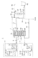
図1に示すように、実施形態1に係る給湯装置(1)は、第1冷媒回路(11)及び第2冷媒回路(9)からなる熱源ヒートポンプと、第1蓄熱ユニット(39)及び第2蓄熱ユニット(37)からなる蓄熱部(7)と、給湯回路(13)とを備えている。給湯装置(1)は、温水を即座に供給することのできる給湯装置である。
【0020】
第1冷媒回路(11)及び第2冷媒回路(9)は、いずれも蒸気圧縮式の冷媒回路である。第1冷媒回路(11)と第2冷媒回路(9)とは、互いに独立した冷媒回路である。冷媒回路(9,11)の冷媒の種類は特に限定されるものではなく、例えばHFC系又はHC系の冷媒等を好適に用いることができる。
【0021】
第1冷媒回路(11)は、圧縮機(31)、第1蓄熱熱交換器(47)、レシーバ(19)、フィルタ(21)、キャピラリチューブ(23)、膨張弁(25)、室外熱交換器(27)、及びアキュムレータ(29)が順に接続されることによって構成されている。第1冷媒回路(11)には、電磁弁(33)及びキャピラリチューブ(35)を有する除霜用回路(34)が設けられている。除霜用回路(34)の一端は圧縮機(31)の吐出側配管に接続され、その他端は室外熱交換器(27)の入口側配管に接続されている。なお、第1冷媒回路(11)の圧縮機(31)や室外熱交換器(27)等は、第1室外ユニット(5)に収納されている。
【0022】
第2冷媒回路(9)は、圧縮機(31)、第2蓄熱熱交換器(41)、レシーバ(19)、フィルタ(21)、キャピラリチューブ(23)、膨張弁(25)、室外熱交換器(27)、及びアキュムレータ(29)が順に接続されることによって構成されている。第2冷媒回路(9)にも、第1冷媒回路(11)と同様に、電磁弁(33)及びキャピラリチューブ(35)を有する除霜用回路(34)が設けられている。第2冷媒回路(9)の圧縮機(31)や室外熱交換器(27)等は、第2室外ユニット(3)に収納されている。
【0023】
室外熱交換器(27)は、いわゆるクロスフィン型のフィン・アンド・チューブ型熱交換器によって構成されている。ただし、室外熱交換器(27)の種類は特に限定されるものではない。
【0024】
第1蓄熱ユニット(39)には、第1の融点を有する第1潜熱蓄熱材が収容され、第2蓄熱ユニット(37)には、第1融点よりも高温の第2融点を有する第2潜熱蓄熱材が収容されている。第1潜熱蓄熱材としては、融点が20℃〜40℃の蓄熱材が好ましく、第2潜熱蓄熱材としては、融点が50℃〜90℃の蓄熱材が好ましい。本実施形態では、第1蓄熱ユニット(39)には、第1潜熱蓄熱材として、融点が約31℃の硫酸ナトリウム10水和物(Na2SO4・10H2O)が収容されている。一方、第2蓄熱ユニット(37)には、第2潜熱蓄熱材として、融点が約55℃の酢酸ナトリウム3水和物(CH3COONa・3H2O)が収容されている。
【0025】
第1蓄熱熱交換器(47)は、第1蓄熱ユニット(39)内において第1潜熱蓄熱材に直接又は間接的に接触するように配置されている。つまり、第1蓄熱熱交換器(47)は、冷媒の凝縮熱によって第1潜熱蓄熱材を加熱するように構成されている。第2蓄熱熱交換器(41)は、第2蓄熱ユニット(37)内において第2潜熱蓄熱材に直接又は間接的に接触するように配置されている。第2蓄熱熱交換器(41)は、冷媒の凝縮熱によって第2潜熱蓄熱材を加熱するように構成されている。
【0026】
第1蓄熱熱交換器(47)及び第2蓄熱熱交換器(41)の熱交換器の種類は特に限定されない。例えば、第1蓄熱熱交換器(47)及び第2蓄熱熱交換器(41)は、裸管式の伝熱管であってもよく、フィンチューブ式の熱交換器等であってもよい。
【0027】
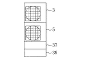
図2に示すように、第1蓄熱ユニット(39)、第2蓄熱ユニット(37)、第1室外ユニット(5)及び第2室外ユニット(3)は順に積層され、一体的に組み立てられている。このことにより、給湯装置(1)の小型化が図られている。
【0028】
図1に示すように、給湯回路(13)は、第1蓄熱ユニット(39)に設けられた第1熱回収熱交換器(49)と、第2蓄熱ユニット(37)に設けられた第2熱回収熱交換器(43)とを備えている。第1熱回収熱交換器(49)及び第2熱回収熱交換器(43)は、給湯回路(13)の水と蓄熱ユニット(39,37)の蓄熱材とを熱交換させる熱交換器であり、蓄熱材に直接又は間接的に接触するように配置されている。第1熱回収熱交換器(49)及び第2熱回収熱交換器(43)の熱交換器の種類も特に限定されず、裸管式の伝熱管で形成されていてもよく、フィンチューブ式の熱交換器等で形成されていてもよい。
【0029】
また、給湯回路(13)には、第2蓄熱ユニット(37)に設けられた追い焚き用熱交換器(45)が設けられている。追い焚き用熱交換器(45)は、追い焚き用回路(15)の水と第2蓄熱ユニット(37)の第2潜熱蓄熱材とを熱交換させるものである。追い焚き用熱交換器(45)の種類も特に限定されるものではなく、裸管式の伝熱管やフィンチューブ式熱交換器等を好適に用いることができる。
【0030】
給湯回路(13)の上流端は上水道に接続され、下流端は給水栓(53)に接続されている。給湯回路(13)には、水道水が流通する。
【0031】
給湯回路(13)は、第1熱回収熱交換器(49)と第2熱回収熱交換器(43)とが順に接続されてなる主回路(14)と、それら熱回収熱交換器(49,43)をバイパスするバイパス回路(59)とを備えている。主回路(14)の下流端とバイパス回路(59)の下流端とは、混合弁(61)に接続されている。混合弁(61)の下流側には、サーミスタ(55)が設けられている。混合弁(61)は、主回路(14)からの高温の温水とバイパス回路(59)からの低温の水道水との混合割合を調整する弁である。本実施形態では、混合割合は、サーミスタ(55)の検出温度が所定温度になるように自動的に調整される。
【0032】
サーミスタ(55)の下流側は、給水栓(53)に接続された給湯配管(62)と、浴槽(65)に接続された風呂注湯管(63)とに分岐している。給湯配管(62)には流量センサ(57)が設けられている。風呂注湯管(63)には、風呂注湯弁(67)が設けられている。
【0033】
追い焚き用回路(15)の一端は浴槽(65)に接続され、他端は風呂注湯管(63)における風呂注湯弁(67)と浴槽(65)との間に接続されている。追い焚き用回路(15)には、ポンプ(69)とサーミスタ(71)とが設けられている。
【0034】
ポンプ(69)が作動すると、浴槽(65)内の温水は追い焚き用回路(15)を流通する。そして、当該温水は追い焚き用熱交換器(45)において加熱され、再び高温の温水となって浴槽(65)に供給される。本実施形態では、追い焚き運転が開始されると、サーミスタ(71)の検出温度が所定温度になるまでポンプ(69)の運転が続けられる。
【0035】
次に、給湯装置(1)の運転について説明する。給湯装置(1)は、蓄熱運転と給湯運転とを実行する。以下、蓄熱運転、給湯運転の順に説明する。
【0036】
蓄熱運転時には、第1冷媒回路(11)及び第2冷媒回路(9)の運転が行われる一方、給湯回路(13)は運転を行わない。第1冷媒回路(11)及び第2冷媒回路(9)では、電磁弁(33)は閉鎖され、圧縮機(31)が駆動される。
【0037】
第1冷媒回路(11)では、圧縮機(31)から吐出された冷媒は、第1蓄熱熱交換器(47)において凝縮し、第1蓄熱ユニット(39)内の第1潜熱蓄熱材を加熱する。これにより、第1潜熱蓄熱材が融解し、第1蓄熱ユニット(39)に温熱が蓄えられる。なお、本実施形態では、蓄熱材の融点が約31℃なので、冷媒と蓄熱材とが約5℃の温度差で熱交換されることで、冷媒の凝縮温度は約36℃でバランスする。
【0038】
第1蓄熱熱交換器(47)で凝縮した冷媒は、レシーバ(19)を通過し、キャピラリチューブ(23)及び膨張弁(25)で減圧され、室外熱交換器(27)で蒸発した後、アキュムレータ(29)を経て圧縮機(31)に吸入される。そして、圧縮機(31)に吸入された冷媒は再び吐出され、上記循環動作を繰り返す。
【0039】
第2冷媒回路(9)では、圧縮機(31)から吐出された冷媒は、第2蓄熱熱交換器(41)において凝縮し、第2蓄熱ユニット(37)内の第2潜熱蓄熱材を加熱する。これにより、第2潜熱蓄熱材が融解し、第2蓄熱ユニット(37)に温熱が蓄えられる。なお、本実施形態では、蓄熱材の融点が約55℃なので、冷媒と蓄熱材とが約5℃の温度差で熱交換されることで、冷媒の凝縮温度は約60℃でバランスする。
【0040】
第2蓄熱熱交換器(41)で凝縮した冷媒は、レシーバ(19)を通過し、キャピラリチューブ(23)及び膨張弁(25)で減圧され、室外熱交換器(27)で蒸発した後、アキュムレータ(29)を経て圧縮機(31)に吸入される。そして、圧縮機(31)に吸入された冷媒は再び吐出され、上記循環動作を繰り返す。
【0041】
給湯運転は、主として蓄熱ユニット(39,37)を熱源とする運転である。給湯運転時には、給湯回路(13)の運転が行われる。また、本実施形態では、給湯運転時にも第1冷媒回路(11)及び第2冷媒回路(9)の運転が行われる。すなわち、第1冷媒回路(11)及び第2冷媒回路(9)も熱源の一部として利用される。
【0042】
第1冷媒回路(11)及び第2冷媒回路(9)の運転動作は蓄熱運転時と同様であるので、それらの説明は省略する。
【0043】
給湯回路(13)では、給水栓(53)又は風呂注湯弁(67)が開放され、上水道から搬送された水道水は給湯回路(13)を流通し、蓄熱ユニット(39,37)で加熱され、温水となって給水される。
【0044】
具体的には、上水道から給湯回路(13)へ流入した水道水は、混合弁(61)のバイパス回路(59)側が開放されている場合には主回路(14)とバイパス回路(59)とに分流し、混合弁(61)のバイパス回路(59)側が閉鎖されている場合には主回路(14)のみに流入する。
【0045】
主回路(14)に流入した水は、第1蓄熱ユニット(39)の第1熱回収熱交換器(49)に流入し、第1潜熱蓄熱材によって加熱される。第1潜熱蓄熱材の融点は約31℃であり、上記水は一定温度で安定して加熱され、約30℃以下の低温の温水となる。
【0046】
次に、上記低温水は、第2蓄熱ユニット(37)の第2熱回収熱交換器(43)に流入し、第2潜熱蓄熱材によって加熱される。第2潜熱蓄熱材の融点は約55℃であり、上記温水は一定温度で安定して加熱され、50℃程度の高温の温水となる。
【0047】
そして、上記高温水は、給湯配管(62)又は風呂注湯管(63)を通じて、給水栓(53)又は浴槽(65)に供給される。なお、混合弁(61)における混合が行われる場合には、上記高温水はバイパス回路(59)からの低温の水道水と混合され、所定温度の温水となって給水栓(53)又は浴槽(65)に供給される。つまり、混合弁(61)を制御することによって、バイパス回路(59)を通じて供給される水道水の水量が調整され、給水栓(53)又は浴槽(65)に供給される温水の温度が調節される。
【0048】
給湯運転時において、浴槽(65)内の温水の温度が低下すると、以下の追い焚き運転が行われる。追い焚き運転は、浴槽(65)の温水を再加熱し、温水の温度を上昇させる運転である。
【0049】
追い焚き運転時には、追い焚き用回路(15)のポンプ(69)が駆動される。すると、浴槽(65)の温水が追い焚き用回路(15)に取り込まれ、当該温水は第2蓄熱ユニット(37)内の追い焚き用熱交換器(45)へ導入される。追い焚き用熱交換器(45)に導入された温水は、追い焚き用熱交換器(45)を介して、第2潜熱蓄熱材によって加熱される。第2潜熱蓄熱材は融点が高いため、上記温水は加熱されることによって高温の温水となる。そして、この高温水は追い焚き用熱交換器(45)を流出し、浴槽(65)に供給される。このように浴槽(65)と追い焚き用熱交換器(45)との間で温水が循環することにより、浴槽(65)内の温水の温度は所定温度にまで上昇する。
【0050】
なお、本給湯装置(1)では、給湯運転時に冷媒回路(11,9)を熱源の一部として利用することから、熱回収熱交換器(49,43)内を流れる水と蓄熱熱交換器(47,41)内を流れる冷媒とを効率よく熱交換させることが望ましい。そのため、第1熱回収熱交換器(49)と第1蓄熱熱交換器(47)、及び第2蓄熱熱交換器(41)と第2蓄熱熱交換器(41)を、それぞれ直接接触させるようにしてもよい。このことにより、熱回収熱交換器(49,43)内を流れる水を蓄熱熱交換器(47,41)内の冷媒によって直接的に加熱することができ、熱交換効率を向上させることができる。
【0051】
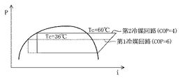
以上のように、本実施形態によれば、それぞれ融点の異なる潜熱蓄熱材を有する第1蓄熱ユニット(39)及び第2蓄熱ユニット(37)を備え、それらに応じて、凝縮温度の低い第1冷媒回路(11)と凝縮温度の高い第2冷媒回路(9)とを設けることとした。したがって、図3に示すように、蓄熱時の第2冷媒回路(9)のCOPは約4程度とやや低いものの、第1冷媒回路(11)のCOPは約6程度であり、高い値を示す。そのため、第1冷媒回路(11)及び第2冷媒回路(9)の全体の平均では、COPは約5程度となり、熱源を単一の冷媒回路で構成する場合に比べて高い値を示す。
【0052】
したがって、本実施形態によれば、冷媒回路(11,9)を大容量化する必要はない。そのため、電気容量を低減することができる。また、室外ユニット(5,3)を大型化する必要がないので、設置スペースを小さく抑えることができる。したがって、一般住宅に対しても無理なく設置することが可能となる。
【0053】
水道水の加熱は、第1熱回収熱交換器(49)及び第2熱回収熱交換器(43)において行われるが、給湯回路(13)において、第2熱回収熱交換器(43)は第1熱回収熱交換器(49)の下流側に設けられている。第2熱回収熱交換器(43)の熱交換温度は第1熱回収熱交換器(49)よりも高いため、水道水は、徐々に熱交換温度が高くなるような順序で加熱されることになる。したがって、水道水は高効率に加熱され、蓄熱は効率よく取り出される。
【0054】
なお、第1蓄熱ユニット(39)又は第2蓄熱ユニット(37)に収容される潜熱蓄熱材は、前述の蓄熱材に限定されず、他の潜熱蓄熱材であってもよい。例えば、他の水和物、パラフィン、糖アルコール等を用いてもよい。また、第1潜熱蓄熱材及び第2潜熱蓄熱材の融点は、前述の値に限定されるものではない。
【0055】
<実施形態2>
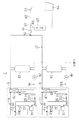
図4に示すように、実施形態2に係る給湯装置(1)は、実施形態1において、第1蓄熱ユニット(39)及び第2蓄熱ユニット(37)の代わりに、第1温水タンク(81)及び第2温水タンク(82)を設けたものである。本実施形態では、温水タンク(81,82)内の水自体が蓄熱材として利用される。
【0056】
本実施形態では、第1蓄熱熱交換器(47)は、液−液熱交換器で構成されている。第1蓄熱熱交換器(47)は第1水回路(11A)に接続されており、第1冷媒回路(11)の冷媒と第1水回路(11A)とを熱交換させる。第1水回路(11A)には、第1温水タンク(81)とポンプ(48)とが設けられている。
【0057】
第2蓄熱熱交換器(41)も液−液熱交換器で構成されている。第2蓄熱熱交換器(41)は第2水回路(9A)に接続されており、第2冷媒回路(9)の冷媒と第2水回路(9A)の水とを熱交換させる。第2水回路(9A)には、第2温水タンク(82)とポンプ(42)とが設けられている。
【0058】
本実施形態では、蓄熱運転時には、第1冷媒回路(11)及び第2冷媒回路(9)が運転を行い、第1蓄熱熱交換器(47)及び第2蓄熱熱交換器(41)において冷媒が凝縮する。なお、第1冷媒回路(11)の冷媒凝縮温度は約85℃程度、第2冷媒回路(9)の冷媒凝縮温度は約45℃程度である。
【0059】
第1水回路(11A)ではポンプ(48)が駆動し、第1温水タンク(81)内の下部に位置する水が第1水回路(11A)に流出する。この水は、第1蓄熱熱交換器(47)において冷媒に加熱され、約40℃の温水となって第1温水タンク(81)内の上部に流入する。
【0060】
第2水回路(9A)ではポンプ(42)が駆動し、第2温水タンク(82)内の下部に位置する水が第2水回路(9A)に流出する。この水は、第2蓄熱熱交換器(41)において冷媒に加熱され、約80℃の温水となって第2温水タンク(82)内の上部に流入する。
【0061】
その結果、蓄熱運転により、第1温水タンク(81)には約40℃程度の温水が蓄えられ、第2温水タンク(82)には約80℃程度の温水が蓄えられる。
【0062】
給湯運転時には、第1温水タンク(81)及び第2温水タンク(82)に蓄えられた温水が供給される。なお、第1温水タンク(81)からの温水と第2温水タンク(82)からの温水とは、混合弁(61)において混合され、所定温度の温水に調整されてから給水栓(53)又は浴槽(65)に供給される。
【0063】
本実施形態においても、給湯運転時には第1冷媒回路(11)及び第2冷媒回路(9)の運転が行われる。また、水回路(11A,9A)のポンプ(48,42)も運転を行う。したがって、温水タンク(81,82)の水の温度が低下しても、温水タンク(81,82)の水は、水回路(11A,9A)を流れることによって冷媒回路(11,9)の蓄熱熱交換器(47,41)で加熱される。そのため、給湯回路(13)を流れる水は、所定温度の温水となって給水栓(53)又は浴槽(65)に供給される。つまり、本実施形態においても、給湯と蓄熱とが同時に実行される。
【0064】
【発明の効果】
請求項1記載の発明によれば、温度レベルの異なる複数の蓄熱部と複数の冷媒回路とを備えることとしたので、処理能力の分散により、冷媒回路の大容量化を抑えることができる。したがって、電気容量の低減及び設置スペースの低減を図ることができ、一般住宅に対しても無理なく設置することが可能となる。
【0065】
請求項2記載の発明によれば、低融点の第1潜熱蓄熱材が収容された第1蓄熱ユニットと、高融点の第2潜熱蓄熱材が収容された第2蓄熱ユニットとを備え、第1蓄熱ユニットに対して第1冷媒回路の凝縮器を設置する一方、第2蓄熱ユニットに対して第2冷媒回路の凝縮器を設置することとした。このように、融点の異なる複数の潜熱蓄熱材に対して別々の冷媒回路を設け、各冷媒回路がそれぞれ独立して蓄熱材への加熱を行うので、凝縮温度の高い第2冷媒回路はCOPが高くなくても、凝縮温度の低い第1冷媒回路はCOPが高くなる。その結果、ヒートポンプ全体の平均COPを向上させることができる。
【0066】
請求項3記載の発明によれば、給湯回路の水と蓄熱手段の蓄熱部との間の熱交換効率を向上させることができる。
【0067】
請求項4記載の発明によれば、温水タンク内の水を蓄熱材として利用することができ、蓄熱手段の構成を簡単化することができるとともに、取り扱いを容易にすることができる。
【図面の簡単な説明】
【図1】実施形態1に係る給湯装置の概略構成図である。
【図2】給湯装置の正面図である。
【図3】第1冷媒回路及び第2冷媒回路における冷媒のモリエル線図である。
【図4】実施形態2に係る給湯装置の概略構成図である。
【符号の説明】
(1) 給湯装置
(3) 第2室外ユニット
(5) 第1室外ユニット
(7) 蓄熱部(蓄熱手段)
(9) 第2冷媒回路
(11) 第1冷媒回路
(13) 給湯回路
(37) 第2蓄熱ユニット
(39) 第1蓄熱ユニット
(41) 第2蓄熱熱交換器(凝縮器)
(43) 第2熱回収熱交換器
(47) 第1蓄熱熱交換器(凝縮器)
(49) 第1熱回収熱交換器[0001]
TECHNICAL FIELD OF THE INVENTION
The present invention relates to a hot water supply device.
[0002]
[Prior art]
BACKGROUND ART Conventionally, as disclosed in
[0003]
[Patent Document 1]
JP-A-9-49668
[Patent Document 2]
JP-A-10-11018
[0004]
[Problems to be solved by the invention]
However, a large-capacity heat pump is required as a heat source in order to immediately tap water at the time of use like a so-called gas instantaneous water heater. For example, when supplying hot water for a shower in winter, if it is attempted to generate 42 liters of hot water at a rate of 12 liters per minute from water at a water temperature of 7 ° C., the heat source heat pump needs a capacity of about 30 kW. Therefore, a heat pump equivalent to 10 horsepower must be prepared as a heat source.
[0005]
However, in the case of a large-capacity heat pump, the size of the outdoor unit is increased, which causes an increase in the size of the hot water supply device. If the outdoor unit is large, installation in a general house becomes extremely difficult. In addition, the required electric capacity greatly exceeds 30 A, so that the power receiving equipment needs to be changed in order to install the electric power in a general house.
[0006]
On the other hand, in order to suppress the capacity of the heat pump, it is conceivable to provide a hot water storage tank in the hot water supply device, store hot water in the hot water storage tank in advance, and supply the hot water at the time of hot water supply. By supplying hot water from the hot water storage tank in this manner, high-temperature hot water can be immediately supplied.
[0007]
However, if the capacity of the hot water storage tank is not large enough, it is not possible to cover the daily hot water supply load. Therefore, a sufficiently large installation space is required in order to install a large-sized hot water storage tank that can cover a daily hot water supply load. Therefore, when installing in a general house, there are many restrictions on the installation location, and in some cases, installation is impossible due to space restrictions.
[0008]
The present invention has been made in view of such a point, and an object of the present invention is to reduce an installation space and an electric capacity in a water heater using a heat pump as a heat source.
[0009]
[Means for Solving the Problems]
The hot water supply apparatus according to
[0010]
Since the hot water supply device has the heat storage means, it is possible to immediately supply high-temperature hot water by using the heat storage. The heat pump serving as a heat source has a first refrigerant circuit and a second refrigerant circuit. That is, it has a plurality of refrigerant circuits. Although hot water of a certain high temperature is indispensable for hot water supply, in the above hot water supply device, the second heat storage unit supplies hot water of a relatively high second temperature. Therefore, at the time of heat storage, the second heat storage unit needs to be heated to a relatively high temperature, and accordingly, the condensation temperature of the second refrigerant circuit becomes relatively high. Therefore, the COP of the second refrigerant circuit is reduced to some extent. However, since the heat storage temperature of the first heat storage unit is relatively low, the refrigerant condensation temperature of the first refrigerant circuit is set lower than the refrigerant condensation temperature of the second refrigerant circuit. Therefore, the COP of the second refrigerant circuit is low, but the COP of the first refrigerant circuit is high. As a result, the average COP of the entire heat pump is higher than in conventional devices where the heat source heat pump is formed of a single refrigerant circuit. Therefore, it is not necessary to increase the capacity of the refrigerant circuit.
[0011]
Further, since the heat source is formed by a plurality of refrigerant circuits, the capacity of each refrigerant circuit can be kept relatively small. Therefore, when the compressor, the evaporator, and the like are formed as an outdoor unit, the outdoor unit is reduced in size and the electric capacity is also reduced. Therefore, it can be installed in a general house without difficulty.
[0012]
The hot water supply apparatus according to claim 2 is the hot water supply apparatus according to
[0013]
In the above hot water supply apparatus, the first heat storage section and the second heat storage section use a latent heat storage material. Therefore, heat storage and use of heat storage are performed efficiently. Since the melting point of each latent heat storage material corresponds to each hot water supply temperature, in each heat storage section, water in the hot water supply circuit is stably heated at a predetermined constant temperature. Therefore, it is possible to stably supply hot water having a predetermined temperature to the hot water supply circuit.
[0014]
The hot water supply apparatus according to
[0015]
In the above hot water supply apparatus, the water in the hot water supply circuit flows in the order of the first heat recovery heat exchanger and the second heat recovery heat exchanger. Therefore, the water in the hot water supply circuit is heated in the order of gradually increasing the heating temperature. Therefore, heat exchange between the water in the hot water supply circuit and the heat storage unit is performed efficiently.
[0016]
In the hot water supply apparatus according to a fourth aspect, in the hot water supply apparatus according to the first aspect, the first heat storage unit includes a first hot water tank (81) that stores water at a first temperature, and the second heat storage unit includes: A second hot water tank (82) for storing water of a second temperature higher than the first temperature is provided. The condenser (47) of the first refrigerant circuit (11) is connected to the first hot water tank (81). The condenser (41) of the second refrigerant circuit (9) is configured to heat the water stored in the second hot water tank (82), and is configured to heat the stored water. The circuit (13) is supplied with hot water of one or both of the first hot water tank (81) and the second hot water tank (82).
[0017]
In the above hot water supply device, water in the hot water tank is used as a heat storage material. At the time of tapping, the hot water in the hot water tank is directly supplied to the hot water supply circuit, and the hot water is used as it is.
[0018]
BEST MODE FOR CARRYING OUT THE INVENTION
Hereinafter, embodiments of the present invention will be described with reference to the drawings.
[0019]
<First embodiment>
As shown in FIG. 1, the hot water supply apparatus (1) according to the first embodiment includes a heat source heat pump including a first refrigerant circuit (11) and a second refrigerant circuit (9), a first heat storage unit (39), and a second heat storage unit (39). A heat storage unit (7) including a heat storage unit (37) and a hot water supply circuit (13) are provided. The hot water supply device (1) is a hot water supply device that can supply hot water immediately.
[0020]
Each of the first refrigerant circuit (11) and the second refrigerant circuit (9) is a vapor compression type refrigerant circuit. The first refrigerant circuit (11) and the second refrigerant circuit (9) are mutually independent refrigerant circuits. The type of refrigerant in the refrigerant circuit (9, 11) is not particularly limited, and for example, an HFC-based or HC-based refrigerant can be suitably used.
[0021]
The first refrigerant circuit (11) includes a compressor (31), a first heat storage heat exchanger (47), a receiver (19), a filter (21), a capillary tube (23), an expansion valve (25), and outdoor heat exchange. The container (27) and the accumulator (29) are connected in order. The first refrigerant circuit (11) is provided with a defrosting circuit (34) having an electromagnetic valve (33) and a capillary tube (35). One end of the defrosting circuit (34) is connected to a discharge-side pipe of the compressor (31), and the other end is connected to an inlet-side pipe of the outdoor heat exchanger (27). The compressor (31) and the outdoor heat exchanger (27) of the first refrigerant circuit (11) are housed in the first outdoor unit (5).
[0022]
The second refrigerant circuit (9) includes a compressor (31), a second heat storage heat exchanger (41), a receiver (19), a filter (21), a capillary tube (23), an expansion valve (25), and outdoor heat exchange. The container (27) and the accumulator (29) are connected in order. Similarly to the first refrigerant circuit (11), the second refrigerant circuit (9) is provided with a defrosting circuit (34) having an electromagnetic valve (33) and a capillary tube (35). The compressor (31) and the outdoor heat exchanger (27) of the second refrigerant circuit (9) are housed in the second outdoor unit (3).
[0023]
The outdoor heat exchanger (27) is constituted by a so-called cross-fin type fin-and-tube heat exchanger. However, the type of the outdoor heat exchanger (27) is not particularly limited.
[0024]
The first heat storage unit (39) contains a first latent heat storage material having a first melting point, and the second heat storage unit (37) has a second latent heat storage material having a second melting point higher than the first melting point. Heat storage material is stored. As the first latent heat storage material, a heat storage material having a melting point of 20C to 40C is preferable, and as the second latent heat storage material, a heat storage material having a melting point of 50C to 90C is preferable. In the present embodiment, the first heat storage unit (39) includes, as a first latent heat storage material, sodium sulfate decahydrate (Na) having a melting point of about 31 ° C. 2 SO 4 ・ 10H 2 O) is accommodated. On the other hand, in the second heat storage unit (37), as a second latent heat storage material, sodium acetate trihydrate (CH) having a melting point of about 55 ° C. 3 COONa 3H 2 O) is accommodated.
[0025]
The first heat storage heat exchanger (47) is arranged to directly or indirectly contact the first latent heat storage material in the first heat storage unit (39). That is, the first heat storage heat exchanger (47) is configured to heat the first latent heat storage material by the heat of condensation of the refrigerant. The second heat storage heat exchanger (41) is disposed in the second heat storage unit (37) so as to directly or indirectly contact the second latent heat storage material. The second heat storage heat exchanger (41) is configured to heat the second latent heat storage material by the heat of condensation of the refrigerant.
[0026]
The types of the heat exchangers of the first heat storage heat exchanger (47) and the second heat storage heat exchanger (41) are not particularly limited. For example, the first heat storage heat exchanger (47) and the second heat storage heat exchanger (41) may be bare tube type heat transfer tubes or fin tube type heat exchangers.
[0027]
As shown in FIG. 2, the first heat storage unit (39), the second heat storage unit (37), the first outdoor unit (5), and the second outdoor unit (3) are sequentially stacked and integrally assembled. . As a result, the size of the hot water supply device (1) is reduced.
[0028]
As shown in FIG. 1, the hot water supply circuit (13) includes a first heat recovery heat exchanger (49) provided in the first heat storage unit (39) and a second heat storage heat exchanger (49) provided in the second heat storage unit (37). A heat recovery heat exchanger (43). The first heat recovery heat exchanger (49) and the second heat recovery heat exchanger (43) are heat exchangers that exchange heat between water in the hot water supply circuit (13) and heat storage materials in the heat storage units (39, 37). And are arranged to directly or indirectly contact the heat storage material. The types of the heat exchangers of the first heat recovery heat exchanger (49) and the second heat recovery heat exchanger (43) are not particularly limited, and may be formed of a bare tube type heat transfer tube, and may be a fin tube type. May be formed by a heat exchanger or the like.
[0029]
Further, the hot water supply circuit (13) is provided with a reheating heat exchanger (45) provided in the second heat storage unit (37). The reheating heat exchanger (45) exchanges heat between the water of the reheating circuit (15) and the second latent heat storage material of the second heat storage unit (37). The type of the reheating heat exchanger (45) is not particularly limited, either, and a bare tube type heat transfer tube, a fin tube type heat exchanger, or the like can be suitably used.
[0030]
The upstream end of the hot water supply circuit (13) is connected to the water supply, and the downstream end is connected to the water tap (53). Tap water flows through the hot water supply circuit (13).
[0031]
The hot water supply circuit (13) includes a main circuit (14) in which a first heat recovery heat exchanger (49) and a second heat recovery heat exchanger (43) are connected in order, and the heat recovery heat exchanger (49). , 43). The downstream end of the main circuit (14) and the downstream end of the bypass circuit (59) are connected to the mixing valve (61). A thermistor (55) is provided downstream of the mixing valve (61). The mixing valve (61) is a valve for adjusting a mixing ratio of high-temperature hot water from the main circuit (14) and low-temperature tap water from the bypass circuit (59). In the present embodiment, the mixing ratio is automatically adjusted so that the temperature detected by the thermistor (55) becomes a predetermined temperature.
[0032]
The downstream side of the thermistor (55) branches into a hot water supply pipe (62) connected to a water tap (53) and a bath pouring pipe (63) connected to a bathtub (65). A flow sensor (57) is provided in the hot water supply pipe (62). The bath pouring pipe (63) is provided with a bath pouring valve (67).
[0033]
One end of the reheating circuit (15) is connected to the bathtub (65), and the other end is connected between the bath injection valve (67) and the bathtub (65) in the bath injection pipe (63). The reheating circuit (15) is provided with a pump (69) and a thermistor (71).
[0034]
When the pump (69) operates, the hot water in the bathtub (65) flows through the reheating circuit (15). Then, the hot water is heated in the reheating heat exchanger (45) and becomes high-temperature hot water again to be supplied to the bathtub (65). In this embodiment, when the reheating operation is started, the operation of the pump (69) is continued until the temperature detected by the thermistor (71) reaches a predetermined temperature.
[0035]
Next, the operation of the hot water supply device (1) will be described. The hot water supply device (1) performs a heat storage operation and a hot water supply operation. Hereinafter, the heat storage operation and the hot water supply operation will be described in this order.
[0036]
During the heat storage operation, the first refrigerant circuit (11) and the second refrigerant circuit (9) are operated, while the hot water supply circuit (13) is not operated. In the first refrigerant circuit (11) and the second refrigerant circuit (9), the solenoid valve (33) is closed, and the compressor (31) is driven.
[0037]
In the first refrigerant circuit (11), the refrigerant discharged from the compressor (31) is condensed in the first heat storage heat exchanger (47) and heats the first latent heat storage material in the first heat storage unit (39). I do. Thereby, the first latent heat storage material is melted, and the heat is stored in the first heat storage unit (39). In the present embodiment, since the melting point of the heat storage material is about 31 ° C., the heat exchange between the refrigerant and the heat storage material is performed at a temperature difference of about 5 ° C., so that the condensation temperature of the refrigerant is balanced at about 36 ° C.
[0038]
The refrigerant condensed in the first heat storage heat exchanger (47) passes through the receiver (19), is depressurized by the capillary tube (23) and the expansion valve (25), and is evaporated in the outdoor heat exchanger (27). It is sucked into the compressor (31) via the accumulator (29). Then, the refrigerant sucked into the compressor (31) is discharged again, and the above-described circulation operation is repeated.
[0039]
In the second refrigerant circuit (9), the refrigerant discharged from the compressor (31) condenses in the second heat storage heat exchanger (41) and heats the second latent heat storage material in the second heat storage unit (37). I do. Thereby, the second latent heat storage material is melted, and the heat is stored in the second heat storage unit (37). In this embodiment, since the melting point of the heat storage material is about 55 ° C., the heat exchange between the refrigerant and the heat storage material is performed at a temperature difference of about 5 ° C., so that the condensation temperature of the refrigerant is balanced at about 60 ° C.
[0040]
The refrigerant condensed in the second heat storage heat exchanger (41) passes through the receiver (19), is depressurized by the capillary tube (23) and the expansion valve (25), and is evaporated in the outdoor heat exchanger (27). It is sucked into the compressor (31) via the accumulator (29). Then, the refrigerant sucked into the compressor (31) is discharged again, and the above-described circulation operation is repeated.
[0041]
The hot water supply operation is an operation mainly using the heat storage units (39, 37) as a heat source. During the hot water supply operation, the operation of the hot water supply circuit (13) is performed. In the present embodiment, the first refrigerant circuit (11) and the second refrigerant circuit (9) are also operated during the hot water supply operation. That is, the first refrigerant circuit (11) and the second refrigerant circuit (9) are also used as a part of the heat source.
[0042]
The operation of the first refrigerant circuit (11) and the operation of the second refrigerant circuit (9) are the same as those during the heat storage operation, and therefore description thereof is omitted.
[0043]
In the hot water supply circuit (13), the water tap (53) or the bath injection valve (67) is opened, and tap water conveyed from the water supply flows through the hot water supply circuit (13) and is heated by the heat storage units (39, 37). It is supplied as warm water.
[0044]
Specifically, the tap water flowing into the hot water supply circuit (13) from the tap water is supplied to the main circuit (14) and the bypass circuit (59) when the bypass circuit (59) side of the mixing valve (61) is open. When the bypass circuit (59) side of the mixing valve (61) is closed, it flows only into the main circuit (14).
[0045]
The water that has flowed into the main circuit (14) flows into the first heat recovery heat exchanger (49) of the first heat storage unit (39), and is heated by the first latent heat storage material. The melting point of the first latent heat storage material is about 31 ° C., and the water is stably heated at a constant temperature to become low-temperature hot water of about 30 ° C. or less.
[0046]
Next, the low-temperature water flows into the second heat recovery heat exchanger (43) of the second heat storage unit (37) and is heated by the second latent heat storage material. The melting point of the second latent heat storage material is about 55 ° C., and the hot water is stably heated at a constant temperature, and becomes high-temperature hot water of about 50 ° C.
[0047]
Then, the high-temperature water is supplied to a water tap (53) or a bathtub (65) through a hot water supply pipe (62) or a bath pouring pipe (63). In addition, when mixing is performed in the mixing valve (61), the high-temperature water is mixed with low-temperature tap water from the bypass circuit (59) to become hot water of a predetermined temperature, and the hydrant (53) or the bathtub ( 65). That is, by controlling the mixing valve (61), the amount of tap water supplied through the bypass circuit (59) is adjusted, and the temperature of the hot water supplied to the water tap (53) or the bathtub (65) is adjusted. You.
[0048]
When the temperature of the hot water in the bathtub (65) decreases during the hot water supply operation, the following reheating operation is performed. The reheating operation is an operation in which the hot water in the bathtub (65) is reheated to increase the temperature of the hot water.
[0049]
During the reheating operation, the pump (69) of the reheating circuit (15) is driven. Then, the hot water in the bathtub (65) is taken into the reheating circuit (15), and the hot water is introduced into the reheating heat exchanger (45) in the second heat storage unit (37). The hot water introduced into the additional heat exchanger (45) is heated by the second latent heat storage material via the additional heat exchanger (45). Since the second latent heat storage material has a high melting point, the hot water becomes high-temperature hot water by being heated. Then, this high-temperature water flows out of the reheating heat exchanger (45) and is supplied to the bathtub (65). By circulating hot water between the bathtub (65) and the additional heat exchanger (45), the temperature of the hot water in the bathtub (65) rises to a predetermined temperature.
[0050]
In the hot water supply apparatus (1), since the refrigerant circuit (11, 9) is used as a part of the heat source during the hot water supply operation, the water flowing in the heat recovery heat exchangers (49, 43) and the heat storage heat exchanger are used. It is desirable to efficiently exchange heat with the refrigerant flowing in (47, 41). Therefore, the first heat recovery heat exchanger (49) and the first heat storage heat exchanger (47), and the second heat storage heat exchanger (41) and the second heat storage heat exchanger (41) are brought into direct contact with each other. It may be. Thereby, water flowing in the heat recovery heat exchangers (49, 43) can be directly heated by the refrigerant in the heat storage heat exchangers (47, 41), and the heat exchange efficiency can be improved. .
[0051]
As described above, according to the present embodiment, the first heat storage unit (39) and the second heat storage unit (37) each having a latent heat storage material having a different melting point are provided. A refrigerant circuit (11) and a second refrigerant circuit (9) having a high condensation temperature are provided. Therefore, as shown in FIG. 3, the COP of the second refrigerant circuit (9) at the time of heat storage is slightly lower at about 4, but the COP of the first refrigerant circuit (11) is about 6, which indicates a high value. . Therefore, the average COP of the entire first refrigerant circuit (11) and the second refrigerant circuit (9) is about 5, which is a higher value than when the heat source is constituted by a single refrigerant circuit.
[0052]
Therefore, according to the present embodiment, it is not necessary to increase the capacity of the refrigerant circuit (11, 9). Therefore, the electric capacity can be reduced. Further, since it is not necessary to increase the size of the outdoor unit (5, 3), the installation space can be reduced. Therefore, it can be easily installed in a general house.
[0053]
The tap water is heated in the first heat recovery heat exchanger (49) and the second heat recovery heat exchanger (43). In the hot water supply circuit (13), the second heat recovery heat exchanger (43) It is provided downstream of the first heat recovery heat exchanger (49). Since the heat exchange temperature of the second heat recovery heat exchanger (43) is higher than that of the first heat recovery heat exchanger (49), tap water is heated in such an order that the heat exchange temperature gradually increases. become. Therefore, tap water is heated with high efficiency, and heat storage is efficiently extracted.
[0054]
In addition, the latent heat storage material accommodated in the first heat storage unit (39) or the second heat storage unit (37) is not limited to the above-described heat storage material, and may be another latent heat storage material. For example, other hydrates, paraffins, sugar alcohols and the like may be used. Further, the melting points of the first latent heat storage material and the second latent heat storage material are not limited to the values described above.
[0055]
<Embodiment 2>
As shown in FIG. 4, the hot water supply apparatus (1) according to the second embodiment is different from the first embodiment in that a first hot water tank (81) is used instead of the first heat storage unit (39) and the second heat storage unit (37). And a second hot water tank (82). In the present embodiment, the water itself in the hot water tank (81, 82) is used as a heat storage material.
[0056]
In the present embodiment, the first heat storage heat exchanger (47) is configured by a liquid-liquid heat exchanger. The first heat storage heat exchanger (47) is connected to the first water circuit (11A) and exchanges heat between the refrigerant in the first refrigerant circuit (11) and the first water circuit (11A). The first water circuit (11A) is provided with a first hot water tank (81) and a pump (48).
[0057]
The second heat storage heat exchanger (41) is also constituted by a liquid-liquid heat exchanger. The second heat storage heat exchanger (41) is connected to the second water circuit (9A) and exchanges heat between the refrigerant in the second refrigerant circuit (9) and the water in the second water circuit (9A). The second water circuit (9A) is provided with a second hot water tank (82) and a pump (42).
[0058]
In the present embodiment, during the heat storage operation, the first refrigerant circuit (11) and the second refrigerant circuit (9) operate, and the refrigerant flows in the first heat storage heat exchanger (47) and the second heat storage heat exchanger (41). Condenses. The refrigerant condensing temperature of the first refrigerant circuit (11) is about 85 ° C, and the refrigerant condensing temperature of the second refrigerant circuit (9) is about 45 ° C.
[0059]
In the first water circuit (11A), the pump (48) is driven, and the water located at the lower part in the first hot water tank (81) flows out to the first water circuit (11A). The water is heated by the refrigerant in the first heat storage heat exchanger (47), becomes hot water of about 40 ° C., and flows into the upper portion of the first hot water tank (81).
[0060]
In the second water circuit (9A), the pump (42) is driven, and the water located at the lower part in the second hot water tank (82) flows out to the second water circuit (9A). This water is heated by the refrigerant in the second heat storage heat exchanger (41), becomes hot water of about 80 ° C., and flows into the upper part of the second hot water tank (82).
[0061]
As a result, by the heat storage operation, the first hot water tank (81) stores hot water of about 40 ° C., and the second hot water tank (82) stores hot water of about 80 ° C.
[0062]
During the hot water supply operation, the hot water stored in the first hot water tank (81) and the second hot water tank (82) is supplied. The hot water from the first hot water tank (81) and the hot water from the second hot water tank (82) are mixed in a mixing valve (61) and adjusted to a predetermined temperature of hot water, and then the water tap (53) or It is supplied to a bathtub (65).
[0063]
Also in the present embodiment, the first refrigerant circuit (11) and the second refrigerant circuit (9) are operated during the hot water supply operation. The pumps (48, 42) of the water circuits (11A, 9A) also operate. Therefore, even if the temperature of the water in the hot water tanks (81, 82) decreases, the water in the hot water tanks (81, 82) flows through the water circuits (11A, 9A) to store heat in the refrigerant circuits (11, 9). Heated by the heat exchangers (47, 41). Therefore, the water flowing in the hot water supply circuit (13) becomes hot water of a predetermined temperature and is supplied to the water tap (53) or the bathtub (65). That is, also in the present embodiment, hot water supply and heat storage are performed simultaneously.
[0064]
【The invention's effect】
According to the first aspect of the present invention, since a plurality of heat storage units and a plurality of refrigerant circuits having different temperature levels are provided, the capacity of the refrigerant circuit can be suppressed from increasing by dispersing the processing capacity. Therefore, it is possible to reduce the electric capacity and the installation space, and it is possible to easily install the system in a general house.
[0065]
According to the invention described in claim 2, the first heat storage unit containing the first latent heat storage material having a low melting point and the second heat storage unit containing the second latent heat storage material having a high melting point are provided. While the condenser of the first refrigerant circuit is provided for the heat storage unit, the condenser of the second refrigerant circuit is provided for the second heat storage unit. As described above, a separate refrigerant circuit is provided for a plurality of latent heat storage materials having different melting points, and each of the refrigerant circuits independently heats the heat storage material. Even if not high, the first refrigerant circuit having a low condensing temperature has a high COP. As a result, the average COP of the entire heat pump can be improved.
[0066]
According to the third aspect of the invention, the heat exchange efficiency between the water in the hot water supply circuit and the heat storage unit of the heat storage means can be improved.
[0067]
According to the invention described in claim 4, water in the hot water tank can be used as a heat storage material, so that the configuration of the heat storage means can be simplified and handling can be facilitated.
[Brief description of the drawings]
FIG. 1 is a schematic configuration diagram of a hot water supply apparatus according to a first embodiment.
FIG. 2 is a front view of the water heater.
FIG. 3 is a Mollier diagram of a refrigerant in a first refrigerant circuit and a second refrigerant circuit.
FIG. 4 is a schematic configuration diagram of a hot water supply apparatus according to a second embodiment.
[Explanation of symbols]
(1) Water heater
(3) Second outdoor unit
(5) First outdoor unit
(7) Heat storage unit (heat storage means)
(9) Second refrigerant circuit
(11) First refrigerant circuit
(13) Hot water supply circuit
(37) Second heat storage unit
(39) First heat storage unit
(41) Second heat storage heat exchanger (condenser)
(43) Second heat recovery heat exchanger
(47) First heat storage heat exchanger (condenser)
(49) First heat recovery heat exchanger
Claims (4)
蓄熱を利用して前記給湯回路(13)に第1の温度の水を供給する第1蓄熱部(39;81)と、蓄熱を利用して前記給湯回路(13)に前記第1温度よりも高い第2温度の水を供給する第2蓄熱部(37;82)とを有する蓄熱手段(7)と、
圧縮機(31)と前記第1蓄熱部(39;81)を加熱する凝縮器(47)と減圧機構(23,25)と蒸発器(27)とを有する第1の冷媒回路(11)と、圧縮機(31)と前記第2蓄熱部(37;82)を加熱する凝縮器(41)と減圧機構(23,25)と蒸発器(27)とを有する第2の冷媒回路(9)とを備えるヒートポンプとを備え、
前記第1冷媒回路(11)の冷媒の凝縮温度が前記第2冷媒回路(9)の冷媒の凝縮温度よりも低く設定されている給湯装置。A hot water supply circuit (13) for circulating water;
A first heat storage unit (39; 81) that supplies water at a first temperature to the hot water supply circuit (13) using heat storage; A heat storage means (7) having a second heat storage part (37; 82) for supplying water of a high second temperature;
A first refrigerant circuit (11) having a compressor (31), a condenser (47) for heating the first heat storage section (39; 81), a pressure reducing mechanism (23, 25), and an evaporator (27); A second refrigerant circuit (9) having a compressor (31), a condenser (41) for heating the second heat storage section (37; 82), a pressure reducing mechanism (23, 25), and an evaporator (27). And a heat pump comprising
A hot water supply apparatus wherein the condensation temperature of the refrigerant in the first refrigerant circuit (11) is set lower than the condensation temperature of the refrigerant in the second refrigerant circuit (9).
第1蓄熱部は、第1の融点を有する第1潜熱蓄熱材を備える第1蓄熱ユニット(39)からなり、
第2蓄熱部は、前記第1融点よりも高温の第2融点を有する第2潜熱蓄熱材を備える第2蓄熱ユニット(37)からなり、
前記第1冷媒回路(11)の凝縮器(47)は、前記第1蓄熱ユニット(39)に設けられ、
前記第2冷媒回路(9)の凝縮器(41)は、前記第2蓄熱ユニット(37)に設けられ、
給湯回路(13)は、前記第1蓄熱ユニット(39)に設けられた第1熱回収熱交換器(49)と、前記第2蓄熱ユニット(37)に設けられた第2熱回収熱交換器(43)とを備えている給湯装置。The hot water supply device according to claim 1,
The first heat storage unit includes a first heat storage unit (39) including a first latent heat storage material having a first melting point,
The second heat storage unit includes a second heat storage unit (37) including a second latent heat storage material having a second melting point higher than the first melting point,
The condenser (47) of the first refrigerant circuit (11) is provided in the first heat storage unit (39),
The condenser (41) of the second refrigerant circuit (9) is provided in the second heat storage unit (37),
The hot water supply circuit (13) includes a first heat recovery heat exchanger (49) provided in the first heat storage unit (39) and a second heat recovery heat exchanger provided in the second heat storage unit (37). (43) A hot water supply device comprising:
給湯回路(13)において、第2熱回収熱交換器(43)は第1熱回収熱交換器(49)の下流側に設けられている給湯装置。The hot water supply device according to claim 2,
In the hot water supply circuit (13), the second heat recovery heat exchanger (43) is a water heater provided downstream of the first heat recovery heat exchanger (49).
第1蓄熱部は、第1温度の水を貯留する第1温水タンク(81)からなり、
第2蓄熱部は、第1温度よりも高温の第2温度の水を貯留する第2温水タンク(82)からなり、
前記第1冷媒回路(11)の凝縮器(47)は、前記第1温水タンク(81)に貯留される水を加熱するように構成され、
前記第2冷媒回路(9)の凝縮器(41)は、前記第2温水タンク(82)に貯留される水を加熱するように構成され、
給湯回路(13)には、前記第1温水タンク(81)及び前記第2温水タンク(82)のうちの一方又は両方の温水が供給される給湯装置。The hot water supply device according to claim 1,
The first heat storage unit includes a first hot water tank (81) for storing water at a first temperature,
The second heat storage unit includes a second hot water tank (82) for storing water at a second temperature higher than the first temperature,
The condenser (47) of the first refrigerant circuit (11) is configured to heat water stored in the first hot water tank (81),
The condenser (41) of the second refrigerant circuit (9) is configured to heat water stored in the second hot water tank (82),
A hot water supply device in which one or both of the first hot water tank (81) and the second hot water tank (82) is supplied to the hot water supply circuit (13).
Priority Applications (1)
| Application Number | Priority Date | Filing Date | Title |
|---|---|---|---|
| JP2002261389A JP3879636B2 (en) | 2002-09-06 | 2002-09-06 | Water heater |
Applications Claiming Priority (1)
| Application Number | Priority Date | Filing Date | Title |
|---|---|---|---|
| JP2002261389A JP3879636B2 (en) | 2002-09-06 | 2002-09-06 | Water heater |
Related Child Applications (1)
| Application Number | Title | Priority Date | Filing Date |
|---|---|---|---|
| JP2006210550A Division JP2006292365A (en) | 2006-08-02 | 2006-08-02 | Hot water supply device |
Publications (2)
| Publication Number | Publication Date |
|---|---|
| JP2004101014A true JP2004101014A (en) | 2004-04-02 |
| JP3879636B2 JP3879636B2 (en) | 2007-02-14 |
Family
ID=32261780
Family Applications (1)
| Application Number | Title | Priority Date | Filing Date |
|---|---|---|---|
| JP2002261389A Expired - Fee Related JP3879636B2 (en) | 2002-09-06 | 2002-09-06 | Water heater |
Country Status (1)
| Country | Link |
|---|---|
| JP (1) | JP3879636B2 (en) |
Cited By (2)
| Publication number | Priority date | Publication date | Assignee | Title |
|---|---|---|---|---|
| JP2009115426A (en) * | 2007-11-09 | 2009-05-28 | Tokyo Electric Power Co Inc:The | Hot water supply system and hot water supply method |
| CN114754520A (en) * | 2022-03-23 | 2022-07-15 | 浙江中广电器集团股份有限公司 | Variable-frequency air source hot water unit with double-coil water tank and control method thereof |
-
2002
- 2002-09-06 JP JP2002261389A patent/JP3879636B2/en not_active Expired - Fee Related
Cited By (2)
| Publication number | Priority date | Publication date | Assignee | Title |
|---|---|---|---|---|
| JP2009115426A (en) * | 2007-11-09 | 2009-05-28 | Tokyo Electric Power Co Inc:The | Hot water supply system and hot water supply method |
| CN114754520A (en) * | 2022-03-23 | 2022-07-15 | 浙江中广电器集团股份有限公司 | Variable-frequency air source hot water unit with double-coil water tank and control method thereof |
Also Published As
| Publication number | Publication date |
|---|---|
| JP3879636B2 (en) | 2007-02-14 |
Similar Documents
| Publication | Publication Date | Title |
|---|---|---|
| CN102216700B (en) | Heat pump system and method of operating | |
| JP5642207B2 (en) | Refrigeration cycle apparatus and refrigeration cycle control method | |
| JP2006292365A (en) | Hot water supply device | |
| WO2008113121A1 (en) | A thermal transfer, recovery and management system | |
| JP2004233010A (en) | Heat pump type water heater | |
| CN105890084B (en) | Hot-water supply system and air conditioner with it | |
| JP6065213B2 (en) | Water heating system | |
| JP5962972B2 (en) | Water heating system | |
| KR100563178B1 (en) | Heat pump type hot water supplier | |
| JP2003232563A (en) | Thermal storage hot water supply apparatus | |
| GB2414289A (en) | A heat pump installation | |
| JP2004101014A (en) | Water heater | |
| JP6066072B2 (en) | Water heating system | |
| JP2007322084A (en) | Heat pump water heater | |
| JP5962971B2 (en) | Water heating system | |
| JP3915635B2 (en) | Water heater | |
| JP3915637B2 (en) | Water heater | |
| JP2013238336A (en) | Water supply heating system | |
| KR102351454B1 (en) | Heating and cooling system with heatpump | |
| EP1766295A1 (en) | Heat pump installation | |
| JP5880266B2 (en) | Water heating system | |
| CN109458735A (en) | Water heater | |
| JP5892371B2 (en) | Water heating system | |
| JP2004211986A (en) | Heat pump hot water feeding system | |
| KR101488903B1 (en) | Heat storaging apparatus and Control process of the same |
Legal Events
| Date | Code | Title | Description |
|---|---|---|---|
| A621 | Written request for application examination |
Free format text: JAPANESE INTERMEDIATE CODE: A621 Effective date: 20050726 |
|
| TRDD | Decision of grant or rejection written | ||
| A01 | Written decision to grant a patent or to grant a registration (utility model) |
Free format text: JAPANESE INTERMEDIATE CODE: A01 Effective date: 20061017 |
|
| A61 | First payment of annual fees (during grant procedure) |
Free format text: JAPANESE INTERMEDIATE CODE: A61 Effective date: 20061030 |
|
| R151 | Written notification of patent or utility model registration |
Ref document number: 3879636 Country of ref document: JP Free format text: JAPANESE INTERMEDIATE CODE: R151 |
|
| FPAY | Renewal fee payment (event date is renewal date of database) |
Free format text: PAYMENT UNTIL: 20101117 Year of fee payment: 4 |
|
| FPAY | Renewal fee payment (event date is renewal date of database) |
Free format text: PAYMENT UNTIL: 20111117 Year of fee payment: 5 |
|
| FPAY | Renewal fee payment (event date is renewal date of database) |
Free format text: PAYMENT UNTIL: 20121117 Year of fee payment: 6 |
|
| FPAY | Renewal fee payment (event date is renewal date of database) |
Free format text: PAYMENT UNTIL: 20121117 Year of fee payment: 6 |
|
| FPAY | Renewal fee payment (event date is renewal date of database) |
Free format text: PAYMENT UNTIL: 20131117 Year of fee payment: 7 |
|
| LAPS | Cancellation because of no payment of annual fees |