CN102216700B - Heat pump system and method of operating - Google Patents
Heat pump system and method of operating Download PDFInfo
- Publication number
- CN102216700B CN102216700B CN200880131928.6A CN200880131928A CN102216700B CN 102216700 B CN102216700 B CN 102216700B CN 200880131928 A CN200880131928 A CN 200880131928A CN 102216700 B CN102216700 B CN 102216700B
- Authority
- CN
- China
- Prior art keywords
- refrigerant
- cold
- producing medium
- heat exchanger
- loop
- Prior art date
- Legal status (The legal status is an assumption and is not a legal conclusion. Google has not performed a legal analysis and makes no representation as to the accuracy of the status listed.)
- Active
Links
Images
Classifications
-
- F—MECHANICAL ENGINEERING; LIGHTING; HEATING; WEAPONS; BLASTING
- F25—REFRIGERATION OR COOLING; COMBINED HEATING AND REFRIGERATION SYSTEMS; HEAT PUMP SYSTEMS; MANUFACTURE OR STORAGE OF ICE; LIQUEFACTION SOLIDIFICATION OF GASES
- F25B—REFRIGERATION MACHINES, PLANTS OR SYSTEMS; COMBINED HEATING AND REFRIGERATION SYSTEMS; HEAT PUMP SYSTEMS
- F25B13/00—Compression machines, plants or systems, with reversible cycle
-
- F—MECHANICAL ENGINEERING; LIGHTING; HEATING; WEAPONS; BLASTING
- F25—REFRIGERATION OR COOLING; COMBINED HEATING AND REFRIGERATION SYSTEMS; HEAT PUMP SYSTEMS; MANUFACTURE OR STORAGE OF ICE; LIQUEFACTION SOLIDIFICATION OF GASES
- F25B—REFRIGERATION MACHINES, PLANTS OR SYSTEMS; COMBINED HEATING AND REFRIGERATION SYSTEMS; HEAT PUMP SYSTEMS
- F25B47/00—Arrangements for preventing or removing deposits or corrosion, not provided for in another subclass
- F25B47/02—Defrosting cycles
- F25B47/022—Defrosting cycles hot gas defrosting
- F25B47/025—Defrosting cycles hot gas defrosting by reversing the cycle
-
- F—MECHANICAL ENGINEERING; LIGHTING; HEATING; WEAPONS; BLASTING
- F25—REFRIGERATION OR COOLING; COMBINED HEATING AND REFRIGERATION SYSTEMS; HEAT PUMP SYSTEMS; MANUFACTURE OR STORAGE OF ICE; LIQUEFACTION SOLIDIFICATION OF GASES
- F25B—REFRIGERATION MACHINES, PLANTS OR SYSTEMS; COMBINED HEATING AND REFRIGERATION SYSTEMS; HEAT PUMP SYSTEMS
- F25B2313/00—Compression machines, plants or systems with reversible cycle not otherwise provided for
- F25B2313/027—Compression machines, plants or systems with reversible cycle not otherwise provided for characterised by the reversing means
- F25B2313/02741—Compression machines, plants or systems with reversible cycle not otherwise provided for characterised by the reversing means using one four-way valve
-
- F—MECHANICAL ENGINEERING; LIGHTING; HEATING; WEAPONS; BLASTING
- F25—REFRIGERATION OR COOLING; COMBINED HEATING AND REFRIGERATION SYSTEMS; HEAT PUMP SYSTEMS; MANUFACTURE OR STORAGE OF ICE; LIQUEFACTION SOLIDIFICATION OF GASES
- F25B—REFRIGERATION MACHINES, PLANTS OR SYSTEMS; COMBINED HEATING AND REFRIGERATION SYSTEMS; HEAT PUMP SYSTEMS
- F25B2400/00—General features or devices for refrigeration machines, plants or systems, combined heating and refrigeration systems or heat-pump systems, i.e. not limited to a particular subgroup of F25B
- F25B2400/04—Refrigeration circuit bypassing means
- F25B2400/0411—Refrigeration circuit bypassing means for the expansion valve or capillary tube
-
- F—MECHANICAL ENGINEERING; LIGHTING; HEATING; WEAPONS; BLASTING
- F25—REFRIGERATION OR COOLING; COMBINED HEATING AND REFRIGERATION SYSTEMS; HEAT PUMP SYSTEMS; MANUFACTURE OR STORAGE OF ICE; LIQUEFACTION SOLIDIFICATION OF GASES
- F25B—REFRIGERATION MACHINES, PLANTS OR SYSTEMS; COMBINED HEATING AND REFRIGERATION SYSTEMS; HEAT PUMP SYSTEMS
- F25B2400/00—General features or devices for refrigeration machines, plants or systems, combined heating and refrigeration systems or heat-pump systems, i.e. not limited to a particular subgroup of F25B
- F25B2400/13—Economisers
-
- F—MECHANICAL ENGINEERING; LIGHTING; HEATING; WEAPONS; BLASTING
- F25—REFRIGERATION OR COOLING; COMBINED HEATING AND REFRIGERATION SYSTEMS; HEAT PUMP SYSTEMS; MANUFACTURE OR STORAGE OF ICE; LIQUEFACTION SOLIDIFICATION OF GASES
- F25B—REFRIGERATION MACHINES, PLANTS OR SYSTEMS; COMBINED HEATING AND REFRIGERATION SYSTEMS; HEAT PUMP SYSTEMS
- F25B2400/00—General features or devices for refrigeration machines, plants or systems, combined heating and refrigeration systems or heat-pump systems, i.e. not limited to a particular subgroup of F25B
- F25B2400/19—Pumping down refrigerant from one part of the cycle to another part of the cycle, e.g. when the cycle is changed from cooling to heating, or before a defrost cycle is started
Landscapes
- Engineering & Computer Science (AREA)
- Physics & Mathematics (AREA)
- Mechanical Engineering (AREA)
- Thermal Sciences (AREA)
- General Engineering & Computer Science (AREA)
- Compression-Type Refrigeration Machines With Reversible Cycles (AREA)
Abstract
A heat pump system operable in a cooling mode, a heating mode and a defrost mode includes a refrigerant compressor (20), a reversing valve (30), a first heat exchanger (40) and a second heat exchanger (50) disposed in a refrigerant circuit, and a primary expansion valve (45) disposed in the refrigerant circuit between said first heat exchanger (40) and said second heat exchanger (50); said reversing valve (30) is positionable in a first position for operation of said heat pump system in the cooling mode or defrost mode and is positionable in a second position for operation of said heat pump system in the heating mode; a refrigerant bypass circuit establishes a refrigerant flow path from the refrigerant circuit at a first location upstream of said primary expansion valve (45) and downstream of said first heat exchanger (40) with respect to refrigerant flow in the defrost mode to a liquid reservoir (70) disposed in the refrigerant circuit at a second location downstream of said primary expansion valve (45) with respect to refrigerant flow in the defrost mode.
Description
Technical field
The present invention relates generally to heat pump, more specifically, relate to refrigerating circuit and the method for operating of air source heat pump.
Background technology
Air source heat pump is used external environment air as being respectively used to the thermal source of heating or cooling another heat transferring medium or heat sink.Conventional air source heat pump comprises in mode well known in the art and is arranged on compressor, reversal valve, First Heat Exchanger, bloating plant and the second heat exchanger in refrigerant vapor compression cycle refrigerant loop.Air source heat pump generally switches between heating mode and refrigerating mode by selective fixed position switching valve.In conventional system, First Heat Exchanger is positioned at outdoor, and when heat pump operates under refrigerating mode, be used as cold-producing medium heat rejection heat exchanger (for example condenser of refrigerant vapour), and when heat pump operates under heating mode, be used as cold-producing medium heat absorption heat exchanger (for example refrigerant evaporator).On the contrary, the second heat exchanger is used as cold-producing medium heat rejection heat exchanger as cold-producing medium heat absorption heat exchanger when heat pump operates under refrigerating mode when heat pump operates under heating mode.
When air source heat pump operates under heating mode, according to outdoor environmental conditions, on the cold-producing medium coil pipe as the First Heat Exchanger of cold-producing medium heat absorption heat exchanger under heating mode, can form and pile up frost.Common way is, by heat pump is switched to, operates one sufficiently long period with heat(ing) coil and melt the frost accumulating on it and then heat pump is switched back under heating mode and operated under refrigerating mode, comes periodically to defrost.When reversal valve is switched back to heating mode from defrosting mode, excessive liquid refrigerant moves to the suction side of compressor.In the refrigerant loop of therefore, being everlasting in conventional air source heat pump system in the compressor suction side of compressor suction entrance upstream, comprise accumulator.Accumulator provides liquid reservoir to collect liquid refrigerant, thereby prevents that liquid refrigerant from leaving in the suction entrance of compressor.Owing to occurring in compressor that liquid refrigerant is unfavorable to compressor performance, wish to avoid liquid refrigerant to enter in compressor.For the large capacity heat pump of routine, the size of suction accumulator must can be processed a large amount of liquid refrigerants.Therefore, suction accumulator expensive in heat pump normally.The appearance of in addition, aspirating accumulator in refrigerant loop has given for the refrigerant pressure drop of passing through thus the cold-producing medium of compressor suction entrance.This extra pressure drop has adverse influence to the coefficient of performance of heat pump.
U.S. Patent No. 4,843,838 disclose a kind of air to the heat pump of air, and it has the indoor coil of being connected to each other and outdoor coil pipe used alternative refrigerant lines.Each of these refrigerant lines comprises check-valves and float valve.Cold-producing medium refrigerating mode operating period flow through these circuits in heating mode operating period, flow through All other routes in the lump.Do not need and removed common trap type accumulator.
Summary of the invention
A kind of heat pump that can operate under refrigerating mode, heating mode and defrosting mode, described heat pump comprises: be positioned at coolant compressor, reversal valve, First Heat Exchanger and second heat exchanger of refrigerant loop, and in described refrigerant loop the main bloating plant between described First Heat Exchanger and described the second heat exchanger.Described reversal valve can be positioned primary importance so that the operation of described heat pump under refrigerating mode, and can be positioned the second place so that the operation of described heat pump under heating mode.
In one aspect of the invention, described heat pump comprises refrigerant bypass loop, described refrigerant bypass loop is set up refrigerant flowpath from the refrigerant loop of primary importance to the liquid reservoir that is positioned at described refrigerant loop at second place place, cold-producing medium stream under the relatively described defrosting mode of described primary importance is in described main bloating plant upstream and in described First Heat Exchanger downstream, and the cold-producing medium stream under the relatively described defrosting mode of the described second place is in described main bloating plant downstream.
In one embodiment, described the second heat exchanger limits the refrigerant collecting chamber that comprises described liquid reservoir.Described the second heat exchanger can be shell and tube exchanger, and described shell and tube exchanger has the shell of restriction described refrigerant collecting chamber and is positioned at the indoor pipe bundle heat exchanger of described refrigerant collecting.In one embodiment, described liquid reservoir comprises the cold-producing medium receiver between described main bloating plant and described the second heat exchanger in described refrigerant loop.
Described bypass circulation can comprise: bypass refrigerant lines, and the cold-producing medium stream under its relatively described defrosting mode is connected to each other described refrigerant loop communicatively at described primary importance place and the described liquid reservoir cold-producing medium stream in described main bloating plant upstream and described First Heat Exchanger downstream; And be placed in the bypass cold-producing medium flow control device in described refrigerant bypass circuit.Described bypass cold-producing medium flow control device can comprise the flow control valve with primary importance and the second place, in bypass refrigerant lines described in described primary importance, cold-producing medium stream is opened, and in bypass refrigerant lines described in the described second place, cold-producing medium stream is closed.In one embodiment, described bypass cold-producing medium flow control device comprises open position/closed position solenoid valve.
In one aspect of the invention, provide operate the method for described heat pump a kind of operating period under defrosting mode.Described heat pump comprises coolant compressor, reversal valve, First Heat Exchanger and the second heat exchanger in refrigerant loop and the main bloating plant between described First Heat Exchanger and described the second heat exchanger in described refrigerant loop.Described reversal valve can be positioned on primary importance so that the operation of described heat pump under refrigerating mode or defrosting mode, and can be positioned on the second place so that the operation of described heat pump under described heating mode.Said method comprising the steps of: start described reversal valve to be switched to its primary importance to operate from its second place under described defrosting mode; Before the operation finishing under described defrosting mode, make cold-producing medium stream by refrigerant bypass loop, lead to refrigerant accumulator from described refrigerant loop; And start described reversal valve to be switched to outside its primary importance.Described method also can comprise the following steps: in described bypass refrigerant loop, provide flow control valve, described flow control valve has open position and closed position, in bypass refrigerant lines described in described open position, cold-producing medium stream is opened, in bypass refrigerant lines described in described closed position, cold-producing medium stream is closed.
The described step by described refrigerant bypass loop can comprise and opens described flow control valve from described refrigerant loop to make cold-producing medium stream.In defrost process, start to make cold-producing medium stream the described step by described refrigerant bypass loop can comprise that the blowdown presssure when described compressor surpasses the first preliminary election blowdown presssure set-point (for example 1650 kPa) from described refrigerant loop by opening described flow control valve, or the frost factor drops to 0%, or defrosting time (for example 8 minutes) is when consume, and opens described flow control valve.If meet any one in these three conditions, flow control valve will start to open.
The step by described refrigerant bypass loop can comprise and closes described flow control valve from described refrigerant loop to stop cold-producing medium stream.By closing described flow control valve, stop cold-producing medium stream the step by described refrigerant bypass loop can be included in the predetermined period and closes the step of described flow control valve having consumed from described refrigerant loop.The size that depends on described flow control valve, the scope of the length of described scheduled time slot can be from one second to 45 seconds or longer.In one embodiment, described scheduled time slot can be about 5 seconds.
Accompanying drawing explanation
For further understanding the present invention, the of the present invention following specific descriptions of reading with reference to connection with figures, in accompanying drawing:
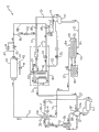
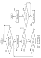
Fig. 1 is the schematic diagram illustrating according to the example embodiment of heat pump of the present invention, and the operation of heat pump under refrigerating mode is shown;
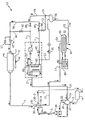
Fig. 2 is the schematic diagram that heat pump shown in Fig. 1 is shown, and the operation of heat pump under heating mode is shown;
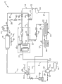
Fig. 3 is the schematic diagram that heat pump shown in Fig. 1 is shown, and heat pump is shown and from defrosting mode, is transformed into the operation of heating mode;
Fig. 4 is the schematic diagram illustrating according to another example embodiment of heat pump of the present invention, heat pump is shown and from defrosting mode, is transformed into the operation of heating mode;
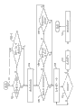
Fig. 5 illustrates for operate the schematic block diagram of example embodiment of the method for heat pump under defrosting mode; And
Fig. 6 illustrates for start the schematic block diagram of example embodiment of the method for heat pump under heating mode.
The specific embodiment
Example embodiment with reference to refrigerant heat pump system shown in Fig. 1-4 10 illustrates the present invention.In all these figure, the direction of cold-producing medium stream is represented by the arrow of refrigerant circuit side.Shown in heat pump 10 are the types that are commonly referred to as air source heat pump.But, be appreciated that and the invention is not restricted to be applied to air source heat pump.
The second port 30-2 of reversal valve 30 is couple to the 4th port 30-4 of reversal valve 30 communicatively by a series of refrigerant lines cold-producing medium stream in reversal valve 30 outsides.In order to operate heat pump 10 under refrigerating mode, reversal valve 30 is optionally positioned at its primary importance, wherein the second port 30-2 of reversal valve 30 is couple to the 4th port 30-4 of reversal valve 30 communicatively by refrigerant lines 7,9A, 11,13,15 and 17 cold-producing medium streams, and described refrigerant lines 7,9A, 11,13,15 check-valves 92 of opening for stream with 17 use are connected with serial flow relation with 98 with the check-valves 96 of closing for stream with 94.In order to operate heat pump 10 under heating mode, reversal valve 30 is optionally positioned at its second place, wherein the 4th port 30-4 is communicatively connected to the second port 30-2 of reversal valve 30 by refrigerant lines 17,15,19,11,9B and 7 cold-producing medium streams, the check-valves 96 that described refrigerant lines 17,15,19,11,9B open for stream with 7 use with 98 and the check-valves 92 of closing for stream be connected with serial flow relation with 94.
Under refrigerating mode, First Heat Exchanger 40 plays the effect of cold-producing medium heat rejection heat exchanger.Under heating mode, First Heat Exchanger 40 plays the effect of cold-producing medium heat absorption heat exchanger.First Heat Exchanger 40 is positioned at outdoor, conventionally on the roof of building that holds climate controlled space or along side of buildings.One or more fans 42 are arranged to be associated with First Heat Exchanger 40 operability, to make outside air pass through First Heat Exchanger, become heat exchanging relation with the cold-producing medium by refrigerant loop.In one embodiment, First Heat Exchanger 40 comprises the heat exchange coil being formed by finned tube array, cold-producing medium thus through with on this pipe outside with fin surface on the outside air of process become heat exchanging relation.
Under refrigerating mode, the second heat exchanger 50 plays the effect of cold-producing medium heat absorption heat exchanger.Under heating mode, the second heat exchanger 50 plays the effect of cold-producing medium heat rejection heat exchanger.In the embodiment shown, the second heat exchanger 50 is couple to air side unit 80 by auxiliary heat-exchanging loop.The second heat exchanger 50 also can be positioned at the outside in climate controlled space, normally outside the building on building roof or along side of buildings.When the second heat exchanger 50, from cold-producing medium and the auxiliary heat-exchanging fluid (normally water or ethylene glycol) of refrigerant loop, become heat exchanging relation.Auxiliary heat-exchanging fluid can pass auxiliary heat-exchanging loop, and wherein, process that auxiliary heat-exchanging fluid and the air extracting by air side unit 80 from climate controlled environment become heat exchanging relation, with cooling before returning to climate controlled environment or heat this air.
In the embodiment shown, the second heat exchanger 50 comprises shell and tube exchanger, and described shell and tube exchanger has the heat-exchanging tube bundle 52 of the inside 55 of the shell 54 that is positioned at the second heat exchanger 50.The inside 55 of shell 54 limits refrigerant collecting chamber.Auxiliary heat-exchanging fluid becomes heat exchanging relation through tube bank 52 with the cold-producing medium of refrigerant loop from heat pump 10.When operation, the inside 55 of shell 54 is full of and has the cold-producing medium from refrigerant loop.This cold-producing medium flows and becomes heat exchanging relation with the auxiliary heat-exchanging fluid that passes through the pipeline of this tube bank on the pipeline external of tube bank 52.This heat-exchanging tube bundle can partly or entirely be immersed in cold-producing medium.In the embodiment shown, tube bank 52 comprises the first heat transfer module of auxiliary heat-exchanging loop, and auxiliary heat-exchanging fluid circulates thus.Auxiliary heat-exchanging loop comprises the second heat transfer module, it comprises that air side unit 80(is such as but not limited to air conditioner unit or fan coil unit) heat exchanger coils 82, wherein auxiliary heat-exchanging fluid becomes heat exchanging relation through described heat exchanger coils 82 with the room air from climate controlled space extraction.In heat exchanger coils 82, through out-of-date, this room air was cooled in refrigerating mode operating period of heat pump 10, and was heated in heating mode operating period of heat pump 10.
As shown in the embodiment of the heat pump 10 shown in Fig. 1-4, heat pump 10 can comprise economizer heat exchanger 60.In the embodiment shown, economizer heat exchanger 60 can comprise that cold-producing medium is to the heat exchanger of cold-producing medium, and it has the first refrigerant loop branch line 62 and the second refrigerant loop branch line 64 arranging with heat exchanging relation.The first refrigerant loop branch line 62 comprises a part for refrigerant lines 11.Second refrigerant loop branch line 64 comprises a part for saver refrigerant lines 21, its upstream position at the first refrigerant loop branch line 62 is switched in refrigerant lines 11 and from this point, is provided to the cold-producing medium circulation flow path of the intermediate pressure port 24 of compressor 20, refrigerant vapour can be injected in the intermediate pressure chamber of compressor 20 thus, and this intermediate pressure is the pressure between swabbing pressure and blowdown presssure.Auxiliary expansion device 65 is positioned at the upstream position of the cold-producing medium stream of the inherent second refrigerant loop relatively of saver refrigerant lines 21 branch line 64.
Saver 60 operation under refrigerating mode and heating mode conventionally, but generally under defrosting mode, do not operate.When saver operates, a part for the liquid refrigerant of process refrigerant lines is transferred to flow through refrigerant lines 21 and through auxiliary expansion device 65.Auxiliary expansion device 65 plays the cold-producing medium of process is therefrom expand into the refrigerant vapour of lower pressure, lower temperature or the effect of liquid/vapor mixture from the refrigerant liquid of elevated pressures, higher temperature.Lower pressure, lower temperature refrigeration agent steam or vapor/liquid mixture become heat exchanging relation through second refrigerant loop branch line 64 with elevated pressures, higher temperature refrigerant liquid through the first refrigerant loop branch line 62, refrigerant liquid is being further cooled through before main bloating plant 45 thus, and the refrigerant vapour of process second refrigerant loop branch line 64 was heated before being injected into the intermediate pressure stage of compression process.Main bloating plant 45 is positioned at the downstream of the cold-producing medium stream of relative the first refrigerant loop branch line 62 of refrigerant lines 11.
Now specifically with reference to Fig. 1, when heat pump 10 operates under refrigerating mode, the hot high-pressure refrigerant vapor process reversal valve 30 discharging through refrigerant lines 3 from compressor 20 is from the first port 30-1 to the second port 30-2, pass through afterwards refrigerant lines 7, pass through afterwards First Heat Exchanger 40, pass through afterwards refrigerant lines 9A, through refrigerant lines 11, pass economizer heat exchanger 60 and main bloating plant 45 afterwards, pass through afterwards refrigerant lines 13, through refrigerant lines 15, pass receiver 70 and the second heat exchanger 50 afterwards, through refrigerant lines 17, arrive reversal valve 30 afterwards.When heat pump 10 operates under refrigerating mode, aid in heat transfer medium becomes heat exchanging relation through the second heat exchanger 50 with the cold-producing medium in the second heat exchanger 50, and cold-producing medium is evaporated and aid in heat transfer medium is cooled thus.In the operation under refrigerating mode, the cold-producing medium that leaves the second heat exchanger 50 process refrigerant lines 17 is comprised of refrigerant vapour, has seldom or does not have liquid refrigerant to leave over.Refrigerant vapour enters from refrigerant lines 17 in the 4th port 30-4 of reversal valve 30, to outside the 3rd port 30-3 of reversal valve 30, and enters then and with the suction entrance 22 by compressor 20, returns to compressor 20 by refrigerant lines 5.
Now specifically with reference to Fig. 2, when heat pump 10 operates under heating mode, the hot high-pressure refrigerant vapor process reversal valve 30 discharging through refrigerant lines 3 from compressor 20 is from the first port 30-1 to the four port 30-4, pass through afterwards refrigerant lines 17, afterwards through the second heat exchanger 50, pass through afterwards refrigerant lines 15 and 19, through receiver 70, through refrigerant lines 11, pass economizer heat exchanger 60 and main bloating plant 45 afterwards, pass through afterwards refrigerant lines 9B, become heat exchanging relation with outdoor air afterwards through First Heat Exchanger 40, through refrigerant lines 7, arrive reversal valve 30 afterwards.When heat pump operates under heating mode, First Heat Exchanger 40 plays the effect of refrigerant evaporator, and the cold-producing medium that leaves thus First Heat Exchanger 40 process refrigerant lines 7 is comprised of refrigerant vapour, has seldom or does not have liquid refrigerant to leave over.Refrigerant vapour enters from refrigerant lines 7 in the second port 30-2 of reversal valve 30, to outside the 3rd port 30-3 of reversal valve 30, and enters then and with the suction entrance 22 by compressor 20, returns to compressor 20 by refrigerant lines 5.
When heat pump 10 operates under heating mode, the hot high-pressure refrigerant vapor that the second heat exchanger 50 receives from compressor discharge.Along with aid in heat transfer medium becomes heat exchanging relation through the second heat exchanger 50 with the refrigerant vapour in the second heat exchanger 50, refrigerant vapour is condensed and aid in heat transfer medium is heated.So, when the operation of heating mode, the second heat exchanger 50 is used as cold-producing medium heat rejection heat exchanger, is also refrigerant condenser.In the operation of heating mode, the cold-producing medium that leaves the second heat exchanger 50 process refrigerant lines 15 is comprised of liquid phase refrigerant.
In temperate climate, during using heat pump, for example, according to external condition (outside air temperature and humidity), in the heating mode operating period of heat pump, on the cold-producing medium delivery heat transfer coil pipe of First Heat Exchanger 40, can form frost.Therefore, when operating heat pump under heating mode, be necessary periodically to interrupt the operation under heating mode and under refrigerating mode, operate the one limited period of heat pump, so that the heat exchange coil defrosting to First Heat Exchanger 40.Under heating mode, operate the switching that can automatically be accomplished to defrosting mode after the default period, or can or in response to operating parameter, complete this switching in response to frost sensor, frost sensor for example for but be not limited to the coil temperature sensor 41 that is operatively associated with the heat exchange coil of First Heat Exchanger 40.Stop defrosting mode and switch back after heating mode also can operate preset period of time under defrosting mode automatically completing, or it can or complete in response to operating parameter in response to the frost sensor being operatively associated with the heat exchange coil of First Heat Exchanger 40.
Now specifically with reference to Fig. 3 and Fig. 4, heat pump 10 is equipped with refrigerant bypass circuit 23, and refrigerant bypass circuit 23 is switched in refrigerant lines 11 in the downstream of the relative cold-producing medium stream of saver 60 and in the position of the upstream of the cold-producing medium stream of relatively main bloating plant 45.In the example embodiment of heat pump shown in Fig. 3 10, refrigerant bypass circuit 23 leads to the interior chamber of receiver 70.In the example embodiment of heat pump shown in Fig. 4 10, refrigerant bypass circuit 23 leads to the refrigerant collecting chamber 55 that the inside by the shell 54 of shell and tube exchanger 50 limits.Bypass flow control appliance 75 is positioned at refrigerant bypass circuit 23.Bypass flow control appliance 75 is optionally positioned at least the first open position and the second closed position.In the situation that bypass flow control appliance 75 is positioned at its open position, cold-producing medium flows to receiver 70 or shell and tube exchanger 50 by refrigerant bypass circuit 23, walks around main bloating plant 45.In the situation that bypass flow control appliance 75 is positioned at its closed position, the cold-producing medium stream by refrigerant bypass circuit 23 is blocked, and continues through main bloating plant 45 by the mobile cold-producing medium of refrigerant lines 11.In one embodiment, bypass flow control appliance 75 can comprise, such as but not limited to, two-position on/off solenoid valve.
During steady state operation at heat pump 10 under heating mode or cooling/defrosting mode, bypass flow control appliance 75 is positioned at closed position.When the operation under defrosting mode stops, reversal valve 30 is reoriented to heating mode position from cooling/defrosting mode position.By reorientation reversal valve 30 before heat pump 10 is transformed into heating mode from defrosting mode, bypass flow control appliance 75 is positioned in open position directly transferring in the refrigerant collecting chamber 55 of receiver 70 or shell and tube exchanger 50 by refrigerant bypass circuit 23 by refrigerant lines 11 flowing liquid cold-producing mediums, and without main bloating plant 45.Owing to not passing through main bloating plant 45 through the mobile cold-producing medium of bypass refrigerant lines 23, this cold-producing medium remains on liquid phase.During migrating out defrosting, the cold-producing medium that passes through refrigerant bypass circuit 23 by transfer flows to be collected in the chamber 55 of receiver 70 or shell and tube exchanger 50, and liquid refrigerant is allowed to directly be sent to the chamber 55 of receiver 70 or shell and tube exchanger 50 from First Heat Exchanger 40.By this way, liquid refrigerant flows out and makes when finishing to get back to heating mode operation from defrosting mode transformation from First Heat Exchanger 40, seldom or do not have liquid refrigerant to stay in First Heat Exchanger 40, make thus when starting to operate under heating mode, it is minimum or disappear that liquid phase refrigerant is introduced in possibility in compressor 20 by suction entrance 22.
Conventionally, heating mode circulated and compressor 20 be closed after (if for example demand for heat be met or in the situation that shutting off power in emergency), reversal valve 30 remains positioned in heating mode position.In the situation that reversal valve 30 is retained in heating location, when restarting compressor 20, liquid refrigerant in the heat exchange coil of First Heat Exchanger 40 can pour in compressor 20, this is that the heat exchange coil of heat exchanger 40 is connected communicatively with suction ports 22 fluids of compressor 20 because be positioned at heating mode lower time when reversal valve 30.Due to a large amount of liquid refrigerants is imported to there is the compressor 20 of suction entrance 22 can be unfavorable to compressor 20, in heat pump 10, it is interior between the heat exchange coil and cold-producing medium branch line 9A and the intersection point of 9B of First Heat Exchanger 40 that parellel arranged flow control valve 43 and flow check valve 47 are placed in refrigerant lines 9.So, about heating mode, the cold-producing medium stream that the cold-producing medium stream in flow control valve 43 loop by First Heat Exchanger 40 relative to flow check valve 47 is positioned at upstream and relatively main bloating plant 45 is positioned at downstream.When cooling or defrosting mode, when flow control valve 43 is closed and when cold-producing medium is just flowing through refrigerant lines 9 from First Heat Exchanger 40, flow check valve 47 provides bypass circulation to walk around flow control valve 43 for cold-producing medium stream.When heating mode, when cold-producing medium just flows in First Heat Exchanger 40 by flow control valve 43 from refrigerant lines 9, flow check valve 47 is closed inherently for stream.
When compressor 20 is restarted under heating mode, for example, after completing defrosting mode, the flow control valve 43 that can be solenoid valve (solenoid valve for example with open position and closed position) is orientated as and is closed, in the heat exchange coil that makes not have liquid refrigerant can flow to First Heat Exchanger 40.Thus, the saturated evaporating temperature SET of the cold-producing medium of refrigerant pressure also so in the heat exchange coil of heat exchanger 40 will decline.Therefore, the liquid refrigerant in heat exchange coil will become refrigerant vapour by start vaporizer.
When refrigerant liquid almost evaporates completely, refrigerant pressure and corresponding saturated evaporating temperature can further reduce.Once the temperature difference between ambient temperature and saturated evaporating temperature reaches predetermined temperature difference set-point, for example during 12 degree Kelvins (21.6 degrees Fahrenheit), flow control valve 43 opens to allow to enter and pass through from the cold-producing medium of refrigerant lines 9 heat exchange coil of heat exchanger 40.When flow control valve 43 is opened at first, conventionally have mixed being clipped in from the heat exchange coil of First Heat Exchanger 40 of liquid refrigerant and enter the refrigerant vapour of compressor 20 by suction entrance 22.Because compressor 20 when compressor starts starts is to operate under low capacity, to the liquid refrigerant relatively in a small amount in compressor 20, be retained in and on compressor 20, do not have harm effect opening the rear a bit of time of flow control valve 43, and be comparatively safe.After compressor is restarted, only the refrigerant pressure between blowdown presssure PD and swabbing pressure PS is poor over predetermined pressure differential, for example, in the time of 350 kPa(kPa), reversal valve just starts to be reoriented to heating mode from defrosting mode, has reduced substantially the risk that while restarting, liquid is left over.If compressor 20 trips in response to alert consitions while operating under defrosting mode, compressor 20 will be restarted after reset under defrosting mode.
Referring now to Fig. 5, with block diagram form, a kind of method that operates heat pump 10 for the operation at defrosting mode is shown.In the embodiment of method as shown in Figure 5, in response to the frost being operatively associated with the heat exchanger coils of outdoor heat exchanger 40, accumulate sensor (such as but not limited to coil temperature sensor 41, thermistor for example), in response to low cold-producing medium swabbing pressure override (override), be activated, and be enabled in operation cycle of heat pump 10 under defrosting mode.At step 102-1, system controller (not shown) monitors the output of coil temperature sensor 41, and according to the output receiving from coil temperature sensor, determines the size of the coil pipe frost factor.If the frost factor reaches 100%, system controller will, first to solenoid valve 75 energy supplies, then start the reorientation of reversal valve 30 from heating mode position to defrosting mode position in step 104.At step 102-2, system controller monitors the temperature that enters the cold-producing medium of compressor 20 by suction entrance 22, and determines whether suction saturation temperature is less than lower limit set-point suction temperatures, for example negative 26.4 degrees Celsius.If suction saturation temperature is less than lower limit set-point suction temperatures and reaches default a period of time, for example 55 seconds, system controller will, in step 104 first to 75 energy supplies of refrigerant bypass flow control device, then start the reorientation of reversal valve 30 from heating mode position to defrosting mode position.
In the situation that reversal valve 30 is positioned at defrosting mode, cold-producing medium flows the refrigerant loop by heat pump 10, as addressed as shown in Fig. 1 about refrigerating mode.During defrosting mode, system controller monitors coil temperature via temperature sensor 41 constantly, for example by software program, monitor the time that defrosting consumes, and for example, via pressure sensor (pressure transducer), monitor the refrigerant pressure at compressor place, for example by the pressure-sensing transducer (not shown) being operatively associated with compressor refrigerant drain line so that the refrigerant pressure at sensing compressor discharge place.At step 106-1, system controller is compared the compressor refrigerant blowdown presssure of institute's sensing with upper limit set-point cold-producing medium blowdown presssure, and upper limit set-point cold-producing medium blowdown presssure is for example but is not limited to 1650 KPa(kPa).At step 106-2, system controller for example, is compared the coil temperature of institute's sensing with set-point coil temperature (14 degrees Celsius), or calculates based on pre-programmed function with by controller and represent that the temperature value of the zero frost factor compares.At step 106-3, system controller is compared the time consuming under defrosting mode with the defrosting maximum permission period of pre-programmed.
If meet any one in three conditions, if also the compressor discharge temperature of institute's sensing has reached upper limit set-point, or the coil temperature of institute's sensing has reached coil temperature set-point, or the lower time consuming of defrosting reached the maximum time limit of defrosting mode, system controller is opened solenoid in step 108 and is opened refrigerant bypass flow control valve 75.In the situation that bypass flow control valve 75 is opened now, cold-producing medium directly flow to liquid reservoir by bypass refrigerant lines 23, flows to the refrigerant collecting chamber 55 of receiver 70 or the second heat exchanger 50, walks around main bloating plant 45.When bypass flow control valve 75 is opened, main expansion valve 45 can remain on initial permanent opening setting when entering defrosting mode, or when opening bypass flow control valve 75, resets and remain on new permanent opening.In step 110, system controller will monitor the time having consumed since bypass flow control valve 75 is opened, and definite bypass flow control valve time period of opened pre-programmed whether, for example 5 seconds, now system will be closed bypass flow control valve 75 and start reversal valve 30 reorientations outside defrosting mode in step 114 in step 112.
When compressor 20 is during under standby or in delaying state, reversal valve 30 will keep compressor 20 original state of operation recently, unless had an accident or shutted off power in emergency when compressor is idle.So, in normal circumstances, if compressor 20 is parked under heating mode, reversal valve 30 will remain on heating mode position, and if compressor 20 is parked under cooling or defrosting mode, reversal valve 30 will continue to remain on cooling/defrosting mode position.If compressor 20 is restarted under refrigerating mode, to the refrigerant liquid in compressor 20, leave over and do not become problem, in the inside 55 limiting because of the shell 54 for by the second heat exchanger, exist enough capacity to collect liquid refrigerant and to prevent that liquid refrigerant from directly advancing in compressor.
Referring now to Fig. 6, if system controller is restarted under heating mode at step 301 prediction compressor 20, for preventing that all liq cold-producing medium in the heat exchange coil of First Heat Exchanger 40 is rushed to suction entrance 22 and is directly entered compressor 20 by refrigerant lines 7 and refrigerant lines 5, system controller will, first in step 302 shutoff solenoid valve 43, make not have refrigerant fluid can enter the heat exchange coil of First Heat Exchanger 40.Then system controller will open compressor 20.At compressor 20, now in the situation that step 303 time operation and solenoid valve 43 are closed, the pressure of the cold-producing medium in the heat exchange coil of First Heat Exchanger 40 and saturation temperature will decline gradually.So, the liquid refrigerant of heat exchange coil inside will flash to steam by the outside air heat absorption from through heat exchange coil.Along with refrigerant pressure and saturation temperature continue to drop to more and more lower, system controller will monitor saturation suction temperatures, and in step 304, saturation suction temperatures is compared with outside air temperature.Once be defined as the temperature difference that outside air temperature deducts saturation suction temperatures, surpassed set-point temperature difference, for example 12 degrees Celsius, system controller will be opened solenoid valve 43 in step 305 and makes can enter in the heat exchange coil of First Heat Exchanger through valve 43 now from the cold-producing medium through expanding of bloating plant 45.
According to above-mentioned method of operating during defrosting mode to the operation of heat pump 10 guarantee to stay when defrosting mode stops all in the coil pipe of first (outdoor) heat exchanger 40 and various refrigerant circuit or substantially all liq cold-producing medium flow in the refrigerant collecting chamber 55 of receiver 70 or the second heat exchanger 50.Therefore, seldom or do not have liquid refrigerant to stay in the coil pipe of First Heat Exchanger 40 or in refrigerant circuit, when defrosting mode is switched to heating mode, these may be left over the suction entrance 22 of compressor 20.Therefore, compare with the typical sizes with the accumulator of the conventional prior art heat pump that can compare capacity, the size of accumulator 74 can significantly reduce.In some fields, use heat pump of the present invention, accumulator 74 even can be removed from refrigerant loop, shown in the example embodiment of routine heat pump 10 as shown in Figure 4.
Below for example, about being equipped with the heat pump of frost sensor (coil temperature sensor 41 being operatively associated with first (outdoor) heat exchanger 40) method of operating under defrosting mode has been described.But be appreciated that, in the situation that do not deviate from the spirit of method of operating of the present invention, heat pump 10 of the present invention also can enter under defrosting mode and operate at the periodicity time interval place of heating mode operation, and before getting back to heating mode, under defrosting mode, operates the limited period of continuity.
Term used herein is the object in order to illustrate rather than to limit.It is restrictive that concrete structure disclosed herein and functional details should not be understood to, and just as instruction those skilled in the art, use basis of the present invention.
Although reference as shown in FIG. example embodiment specifically illustrates and illustrated the present invention, it will be recognized by those skilled in the art in the situation that not deviating from spirit and scope of the invention and can make various modifications.It will be recognized by those skilled in the art that equivalent can replace not deviating from scope of the present invention with reference to the element described in example embodiment disclosed herein.Therefore, institute is intended that, the disclosure is not limited to disclosed (one or more) specific embodiment, but the disclosure will comprise all embodiment that fall within the scope of claims.
Claims (17)
- One kind can be at refrigerating mode, the heat pump operating under heating mode and defrosting mode, described heat pump comprises: the coolant compressor that is positioned at refrigerant loop, reversal valve, First Heat Exchanger and the second heat exchanger, and in described refrigerant loop the main bloating plant between described First Heat Exchanger and described the second heat exchanger, described reversal valve can be positioned primary importance so that the operation of described heat pump under described refrigerating mode or defrosting mode, and the second place can be positioned so that the operation of described heat pump under described heating mode, described heat pump is also characterised in that and comprises:Refrigerant bypass loop, described refrigerant bypass loop is set up refrigerant flowpath from the refrigerant loop of primary importance to the liquid reservoir that is positioned at described refrigerant loop at second place place, cold-producing medium stream under the relatively described defrosting mode of described primary importance is in described main bloating plant upstream and in described First Heat Exchanger downstream, and the cold-producing medium stream under the relatively described defrosting mode of the described second place is in described main bloating plant downstream.
- 2. heat pump as claimed in claim 1, is further characterized in that, described the second heat exchanger limits the refrigerant collecting chamber that comprises described liquid reservoir.
- 3. heat pump as claimed in claim 2, is further characterized in that, described the second heat exchanger comprises shell and tube exchanger, and described shell and tube exchanger has the shell of restriction described refrigerant collecting chamber and is positioned at the indoor pipe bundle heat exchanger of described refrigerant collecting.
- 4. heat pump as claimed in claim 1, is further characterized in that, described liquid reservoir comprises the cold-producing medium receiver between described main bloating plant and described the second heat exchanger in described refrigerant loop.
- 5. heat pump as claimed in claim 1, is further characterized in that, described refrigerant bypass loop comprises:Bypass refrigerant lines, the cold-producing medium stream under its relatively described defrosting mode is connected to each other described refrigerant loop communicatively at described primary importance place and the described liquid reservoir cold-producing medium stream in described main bloating plant upstream and described First Heat Exchanger downstream; AndBe placed in the bypass cold-producing medium flow control device in described bypass refrigerant lines.
- 6. heat pump as claimed in claim 5, be further characterized in that, described bypass cold-producing medium flow control device comprises the flow control valve with primary importance and the second place, in bypass refrigerant lines described in described primary importance, cold-producing medium stream is opened, in bypass refrigerant lines described in the described second place, cold-producing medium stream is closed.
- 7. heat pump as claimed in claim 5, is further characterized in that, described bypass cold-producing medium flow control device comprises open position/closed position solenoid valve.
- 8. heat pump as claimed in claim 1, is also further characterized in that and comprises:Under heating mode, the cold-producing medium stream by described refrigerant loop is positioned at described refrigerant loop at the flow control valve in described First Heat Exchanger upstream and main bloating plant downstream relatively; AndBe positioned at described refrigerant loop and become the flow check valve of concurrency relation with described flow control valve.
- 9. the method at defrosting mode manipulate heat pump, described heat pump comprises the coolant compressor that is positioned at refrigerant loop, reversal valve, First Heat Exchanger and the second heat exchanger and in described refrigerant loop the main bloating plant between described First Heat Exchanger and described the second heat exchanger, described reversal valve can be positioned at primary importance so that the operation of described heat pump under described refrigerating mode or defrosting mode, and the second place can be positioned at so that the operation of described heat pump under described heating mode, described method is characterised in that following steps:Start described reversal valve to be switched to its primary importance to operate from its second place under described defrosting mode;Before the operation finishing under described defrosting mode, make cold-producing medium stream by refrigerant bypass loop, lead to liquid reservoir from described refrigerant loop, described refrigerant bypass loop is set up refrigerant flowpath from the refrigerant loop of primary importance to the liquid reservoir that is positioned at described refrigerant loop at second place place, cold-producing medium stream under the relatively described defrosting mode of described primary importance is in described main bloating plant upstream and in described First Heat Exchanger downstream, and the cold-producing medium stream under the relatively described defrosting mode of the described second place is in described main bloating plant downstream;AndStart described reversal valve to be switched to outside its primary importance.
- 10. method as claimed in claim 9, is further characterized in that:In described refrigerant bypass loop, provide flow control valve, described flow control valve has open position and closed position, in refrigerant bypass loop described in described open position, cold-producing medium stream is opened, in refrigerant bypass loop described in described closed position, cold-producing medium stream is closed; AndThe described step by described refrigerant bypass loop comprises and opens described flow control valve from described refrigerant loop to make cold-producing medium stream.
- 11. methods as claimed in claim 10, be further characterized in that, by opening described flow control valve, make cold-producing medium stream when the described step by described refrigerant bypass loop comprises that blowdown presssure when described compressor is over the first preliminary election blowdown presssure set-point from described refrigerant loop, under defrosting mode, open described flow control valve.
- 12. methods as claimed in claim 10, be further characterized in that, by opening described flow control valve, make cold-producing medium stream the described step by described refrigerant bypass loop comprises and when the frost factor of described First Heat Exchanger drops to 0%, under defrosting mode, opens described flow control valve from described refrigerant loop.
- 13. methods as claimed in claim 10, be further characterized in that, by opening described flow control valve, make cold-producing medium stream when the described step by described refrigerant bypass loop comprises that the time consuming when defrosting mode reaches eight minutes from described refrigerant loop, under defrosting mode, open described flow control valve.
- 14. methods as claimed in claim 10, are further characterized in that, by closing described flow control valve termination cold-producing medium, flow from described refrigerant loop by the step in described refrigerant bypass loop.
- 15. methods as claimed in claim 14, are further characterized in that, the step by described refrigerant bypass loop is included in the described preliminary election period and closes described flow control valve while expiring from described refrigerant loop to stop cold-producing medium stream.
- 16. methods as claimed in claim 15, are further characterized in that, the scope of described preliminary election period was from one second to 45 seconds.
- 17. methods as claimed in claim 16, are further characterized in that, the described preliminary election period is 5 seconds.
Applications Claiming Priority (1)
| Application Number | Priority Date | Filing Date | Title |
|---|---|---|---|
| PCT/CN2008/001866 WO2010054498A1 (en) | 2008-11-11 | 2008-11-11 | Heat pump system and method of operating |
Publications (2)
| Publication Number | Publication Date |
|---|---|
| CN102216700A CN102216700A (en) | 2011-10-12 |
| CN102216700B true CN102216700B (en) | 2014-04-02 |
Family
ID=42169576
Family Applications (1)
| Application Number | Title | Priority Date | Filing Date |
|---|---|---|---|
| CN200880131928.6A Active CN102216700B (en) | 2008-11-11 | 2008-11-11 | Heat pump system and method of operating |
Country Status (4)
| Country | Link |
|---|---|
| US (1) | US20110203299A1 (en) |
| EP (1) | EP2347196A1 (en) |
| CN (1) | CN102216700B (en) |
| WO (1) | WO2010054498A1 (en) |
Families Citing this family (21)
| Publication number | Priority date | Publication date | Assignee | Title |
|---|---|---|---|---|
| JP5653451B2 (en) * | 2010-11-24 | 2015-01-14 | 三菱電機株式会社 | Heat pump type water heater |
| JP5240332B2 (en) * | 2011-09-01 | 2013-07-17 | ダイキン工業株式会社 | Refrigeration equipment |
| EP2927623B1 (en) * | 2012-11-29 | 2019-02-06 | Mitsubishi Electric Corporation | Air-conditioning device |
| US10317112B2 (en) | 2014-04-04 | 2019-06-11 | Johnson Controls Technology Company | Heat pump system with multiple operating modes |
| KR101566747B1 (en) * | 2014-04-14 | 2015-11-13 | 현대자동차 주식회사 | Heat pump system for vehicle |
| US10119738B2 (en) | 2014-09-26 | 2018-11-06 | Waterfurnace International Inc. | Air conditioning system with vapor injection compressor |
| CN104457067B (en) * | 2014-09-30 | 2017-04-19 | 烟台万德嘉空调设备有限公司 | Energy-saving quick defroster |
| SG10201903371VA (en) * | 2014-10-14 | 2019-05-30 | Cass Khoo | Efficiency enhancing apparatus and methods for a heat exchange system |
| CN105823267B (en) * | 2015-01-08 | 2020-06-05 | 开利公司 | Heat pump system and adjusting method thereof |
| CN104748239B (en) * | 2015-03-31 | 2017-10-31 | 广东美的暖通设备有限公司 | Multiple on-line system |
| US10119730B2 (en) * | 2016-02-08 | 2018-11-06 | Vertiv Corporation | Hybrid air handler cooling unit with bi-modal heat exchanger |
| US10871314B2 (en) | 2016-07-08 | 2020-12-22 | Climate Master, Inc. | Heat pump and water heater |
| US10866002B2 (en) | 2016-11-09 | 2020-12-15 | Climate Master, Inc. | Hybrid heat pump with improved dehumidification |
| EP3635304B1 (en) * | 2017-06-08 | 2022-03-23 | Carrier Corporation | Method of control for economizer of transport refrigeration units |
| US10935260B2 (en) | 2017-12-12 | 2021-03-02 | Climate Master, Inc. | Heat pump with dehumidification |
| US11073313B2 (en) * | 2018-01-11 | 2021-07-27 | Carrier Corporation | Method of managing compressor start for transport refrigeration system |
| US11592215B2 (en) | 2018-08-29 | 2023-02-28 | Waterfurnace International, Inc. | Integrated demand water heating using a capacity modulated heat pump with desuperheater |
| CA3081986A1 (en) | 2019-07-15 | 2021-01-15 | Climate Master, Inc. | Air conditioning system with capacity control and controlled hot water generation |
| CN112303950A (en) * | 2020-10-29 | 2021-02-02 | 珠海格力电器股份有限公司 | Heat exchange system and air conditioning equipment with same |
| WO2022155129A2 (en) * | 2021-01-12 | 2022-07-21 | Rheem Manufacturing Company | Interlaced microchannel heat exchanger systems and methods thereto |
| CN114909815A (en) * | 2021-02-09 | 2022-08-16 | 特灵国际有限公司 | Reversible heat pump |
Citations (7)
| Publication number | Priority date | Publication date | Assignee | Title |
|---|---|---|---|---|
| US5651261A (en) * | 1993-10-29 | 1997-07-29 | Daikin Industries, Ltd. | Operation control device for air conditioner |
| CN1313494A (en) * | 2000-03-15 | 2001-09-19 | 开利公司 | Method and system for control of defrosting reversible heat pump |
| US6449967B1 (en) * | 2001-06-12 | 2002-09-17 | DUBé SERGE | High speed evaporator defrost system |
| CN2596284Y (en) * | 2003-01-05 | 2003-12-31 | 游可方 | Multiple heat pump with pre-evaporation and de-frosting device |
| CN2605538Y (en) * | 2003-01-23 | 2004-03-03 | 清华同方人工环境有限公司 | Bypass defrosting apparatus for heat pump set |
| CN2896146Y (en) * | 2006-04-11 | 2007-05-02 | 珠海格力电器股份有限公司 | Heat pump air conditioning system and steam injection control device thereof |
| CN200961977Y (en) * | 2006-09-20 | 2007-10-17 | 昆山台佳机电有限公司 | Oil-returning device for defrosting the wind cooling screw cold water heat pump unit |
Family Cites Families (10)
| Publication number | Priority date | Publication date | Assignee | Title |
|---|---|---|---|---|
| US4502292A (en) * | 1982-11-03 | 1985-03-05 | Hussmann Corporation | Climatic control system |
| JPS6325471A (en) * | 1986-07-17 | 1988-02-02 | 三菱電機株式会社 | Air conditioner |
| US5105629A (en) * | 1991-02-28 | 1992-04-21 | Parris Jesse W | Heat pump system |
| JPH10103795A (en) * | 1996-09-26 | 1998-04-21 | Hitachi Ltd | Water cooled refrigerating device |
| JP3008925B2 (en) * | 1998-04-10 | 2000-02-14 | ダイキン工業株式会社 | Refrigeration equipment |
| CA2432143A1 (en) * | 1999-12-23 | 2001-06-28 | James Ross | Hot discharge gas desuperheater |
| US6684650B2 (en) * | 2002-01-24 | 2004-02-03 | Carrier Corporation | System and method for rapid defrost or heating in a mobile refrigeration unit |
| JP4123829B2 (en) * | 2002-05-28 | 2008-07-23 | 三菱電機株式会社 | Refrigeration cycle equipment |
| CN100575818C (en) * | 2005-06-03 | 2009-12-30 | 开利公司 | Heat pump with auxiliary water heating |
| US20070251256A1 (en) * | 2006-03-20 | 2007-11-01 | Pham Hung M | Flash tank design and control for heat pumps |
-
2008
- 2008-11-11 CN CN200880131928.6A patent/CN102216700B/en active Active
- 2008-11-11 EP EP08878058A patent/EP2347196A1/en not_active Withdrawn
- 2008-11-11 US US13/126,046 patent/US20110203299A1/en not_active Abandoned
- 2008-11-11 WO PCT/CN2008/001866 patent/WO2010054498A1/en active Application Filing
Patent Citations (7)
| Publication number | Priority date | Publication date | Assignee | Title |
|---|---|---|---|---|
| US5651261A (en) * | 1993-10-29 | 1997-07-29 | Daikin Industries, Ltd. | Operation control device for air conditioner |
| CN1313494A (en) * | 2000-03-15 | 2001-09-19 | 开利公司 | Method and system for control of defrosting reversible heat pump |
| US6449967B1 (en) * | 2001-06-12 | 2002-09-17 | DUBé SERGE | High speed evaporator defrost system |
| CN2596284Y (en) * | 2003-01-05 | 2003-12-31 | 游可方 | Multiple heat pump with pre-evaporation and de-frosting device |
| CN2605538Y (en) * | 2003-01-23 | 2004-03-03 | 清华同方人工环境有限公司 | Bypass defrosting apparatus for heat pump set |
| CN2896146Y (en) * | 2006-04-11 | 2007-05-02 | 珠海格力电器股份有限公司 | Heat pump air conditioning system and steam injection control device thereof |
| CN200961977Y (en) * | 2006-09-20 | 2007-10-17 | 昆山台佳机电有限公司 | Oil-returning device for defrosting the wind cooling screw cold water heat pump unit |
Also Published As
| Publication number | Publication date |
|---|---|
| US20110203299A1 (en) | 2011-08-25 |
| EP2347196A1 (en) | 2011-07-27 |
| WO2010054498A1 (en) | 2010-05-20 |
| CN102216700A (en) | 2011-10-12 |
Similar Documents
| Publication | Publication Date | Title |
|---|---|---|
| CN102216700B (en) | Heat pump system and method of operating | |
| CN102272534B (en) | Air conditioning apparatus | |
| US9897349B2 (en) | Refrigeration cycle device | |
| EP2211127A1 (en) | Heat pump type air conditioner | |
| CN104061705A (en) | Two-stage compression air conditioning system and control method thereof | |
| EP2530411B1 (en) | Refrigeration cycle equipment | |
| EP3722709A1 (en) | Heat pump system and control method therefor | |
| JP2006284035A (en) | Air conditioner and its control method | |
| JP5375904B2 (en) | Air conditioner | |
| JP7034227B1 (en) | Air conditioner and management device | |
| CN102967118A (en) | Refrigerator defrosting control method and refrigerator adopting method | |
| JP5333507B2 (en) | Heat pump water heater | |
| KR100712196B1 (en) | Heat pump system and a method for eliminating frost on the outdoor heat exchanger of the heat pump system | |
| JP3993540B2 (en) | Refrigeration equipment | |
| JP2013108730A (en) | Air conditioner | |
| JP2004278813A (en) | Air-conditioner and its controlling method | |
| CN204535185U (en) | Heat recovery air conditioner unit | |
| KR20140097858A (en) | Heat pump | |
| CN206146042U (en) | Heat pump system and refrigerating unit | |
| CN113685916A (en) | Air conditioning system and control method thereof | |
| JP2011127775A (en) | Air conditioner | |
| CN111578450A (en) | Air conditioning system and defrosting method thereof | |
| JP2006029637A (en) | Heat storage type air conditioner and its operation method | |
| CN220287825U (en) | Refrigerant system and air conditioner | |
| JP6103181B2 (en) | Engine-driven air conditioner |
Legal Events
| Date | Code | Title | Description |
|---|---|---|---|
| C06 | Publication | ||
| PB01 | Publication | ||
| C10 | Entry into substantive examination | ||
| SE01 | Entry into force of request for substantive examination | ||
| REG | Reference to a national code |
Ref country code: HK Ref legal event code: DE Ref document number: 1162654 Country of ref document: HK |
|
| C14 | Grant of patent or utility model | ||
| GR01 | Patent grant | ||
| REG | Reference to a national code |
Ref country code: HK Ref legal event code: WD Ref document number: 1162654 Country of ref document: HK |