JP2004069428A - Atomic force and molecular force microscope - Google Patents
Atomic force and molecular force microscope Download PDFInfo
- Publication number
- JP2004069428A JP2004069428A JP2002227569A JP2002227569A JP2004069428A JP 2004069428 A JP2004069428 A JP 2004069428A JP 2002227569 A JP2002227569 A JP 2002227569A JP 2002227569 A JP2002227569 A JP 2002227569A JP 2004069428 A JP2004069428 A JP 2004069428A
- Authority
- JP
- Japan
- Prior art keywords
- light
- sample
- cantilever
- laser
- atomic
- Prior art date
- Legal status (The legal status is an assumption and is not a legal conclusion. Google has not performed a legal analysis and makes no representation as to the accuracy of the status listed.)
- Pending
Links
Images


Abstract
Description
【0001】
【発明の属する技術分野】
本発明は、試料表面の情報を高い分解能で生態メカニズムを経時的に観察測定することのできる走査型プローブ顕微鏡等に関する。
【0002】
【従来の技術】
走査型プローブ顕微鏡のひとつに原子間力顕微鏡(AFM)がある。これは微細加工によって作られたカンチレバーを試料に接触または近接させ、カンチレバーの先端に付けられた探針と試料間に働く原子間力によるカンチレバーのたわみを検出することにより、試料表面の形状を測定するものである。カンチレバーのたわみを測定する手段としては、光テコ法や光干渉計やピエゾ抵抗等があげられるが、最も簡便な手段である光テコ法が最も多く用いられている。
【0003】
この原子間力顕微鏡は、光学顕微鏡を遙かに上回る分解能を持ちながら、電子顕微鏡のように試料を真空中に入れる必要がない、という利点を有している。従って、空気中や、水溶液をはじめ各種液体中でも観察できる。
【0004】
また他の利点として、有機分子、DNA、蛋白質、蛋白質集合体であるアクチン、微小管、バクテリアの繊毛、各種細胞骨格、核膜と核孔、ウイルスなどの微細構造を固定や染色をせずにとらえることができる。さらに、培養中の生きている動物細胞の微細な形態変化を時間を追って観察することができる。
【0005】
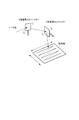
従来のAFM装置の典型的な構成例を説明する。図9は、従来の典型的なAFMの全体構成を示す模式図である。この図の装置は、倒立型顕微鏡270と一体化されており、透過照明装置274を備えている。試料211は、ステージ271に載せられ支持されている。カンチレバー207の先端部下面には、探針209が下方に突出するように形成されている。カンチレバー207の先端の探針209は試料211の表面に当てられている。円筒形XYZスキャナー213は、試料面上に対して水平方向(X,Y)と垂直方向(Z)にカンチレバー207を走査する。円筒形XYZスキャナー213は、通常は、ピエゾアクチュエータで構成されており、顕微鏡270のアーム275に固定されている。カンチレバー207は、一般的に剛性の高いアームを介して支柱に保持されている。
【0006】
カンチレバー207の上面には、装置上方に設置されている変位測定用のレーザ発振器221から、レーザ光(入射光231)が当てられる。この入射光231は、カンチレバー207の上面に焦点が合った状態で、その表面上で反射される。その反射光232は、上方に設置されている検出器235に当る。
【0007】
検出器235は、例えば上下二分割型のフォトディテクタ(PD)で構成され、図10に示されるように、上下に並べて配置された二つのセンサ、すなわち上側センサAと下側センサBを有しており、反射光232の入射位置を検出することができる。例えば、反射光232が上側に当たると、上側センサAの光量の方が下側センサBの光量よりも多くなる。反射光232が下に当たると逆となる。
【0008】
PD235の信号は、アナログ信号のため、A/D変換器261で一旦デジタル信号に変換され、データ処理部262に送られる。データ処理部262は、PD235の各センサAとBの信号の和信号と差信号を算出し、その結果は、システム全体を制御するCPU257を介して、Z走査駆動制御部263とXY走査駆動制御部264に制御信号として送られる。Z走査駆動制御部263とXY走査駆動制御部264は送られてくる制御信号に従って円筒形XYZスキャナー213を駆動する。また、CPU257は、取得したデータに基づいて所望のデータを表示部255に表示させる。
【0009】
次に、図9のAFMの調整及び動作について説明する。最初、レーザ発振器221からレーザ光をカンチレバー探針209の先端の表面上に合わせる必要がある。そのため、位置と焦点面が一致するように、レーザ発振器221の位置を組立調整時又は測定前に精密に調整する。次に、その反射レーザ光232を二分割PD235の指定した中心位置に合わせる調整が必要である。二分割PD235の和信号(A+B)が最大になるようにレーザ入射光231の位置を調節し、次に差信号(A−B)が最小になるように二分割PD235の位置を調整する。
【0010】
これらの調整が終わった後にカンチレバー207を試料に接触させ、サンプルスキャンの場合は試料211をカンチレバー207で走査する。このとき二分割PD235の差信号をモニタすることによって、試料211表面の形状を表示部255で画像表示することができる。また、二分割PD235の差信号が一定になるように、すなわちカンチレバー207と試料211の間に働く力が一定になるようにフィードバックをかけながら、試料表面の形状を画像化することも可能である。また、検出器235は四分割PDが用いられてもよい。
【0011】
上記の制御を行うことにより、たわみとねじれを一定値に保つように制御しながら走査し、各々の制御電圧の結果を画像化することにより、試料表面の形状が分かる。
【0012】
また、表面形状観察以外の測定方法には、注目する分子の力定数測定がある。これは、Z方向の制御を行うのみで実行できる。
【0013】
また、光学顕微鏡を用いた光学観察は、透過照明装置274から照明し、対物レンズ272を通して接眼レンズ273で観察ができる。これにより、AFM観察を行いながら、試料全体の光学像が観察でき、測定位置等が容易に確認できる。
【0014】
一方、AFM観察が普及されるかなり前から、生態観察においては蛍光を利用した観察もバイオイメージングとして広く利用されている。これは、蛍光試薬を蛍光標識として生態内に取り込み、光励起し発生する蛍光信号を観察する。CCDカメラで像を検出することで、又は励起光を走査することで画像が得られる。さらに、それを発展させた研究では、単なる蛍光画像化にとどまらず、光刺激などを応用した生物フィジオロジーアプリケーションがある。
【0015】
例えば、Cagedは、細胞内で(局所的に)活性物質の濃度を上昇させ、どのような反応が引き起こされるかを観察できるという手法である。従来、細胞外から何らかの刺激を働きかけることで活性化する物質、例えば神経伝達物質、ホルモン、細胞内情報伝達物質が注目されている。これらは、すぐに働き出してしまう反応性分子であるが、反応前には不活性なかたちで細胞に導入しておき、光照射を与えると分子が動き出し反応が開始するようにする。この光照射のタイミングが反応開始のトリガーになり、その後の変化や反応の現象を経時的に画像化して捉える。これらを観察し生態のメカニズムを解明する手がかりをつかんでいく。この場合、一般的に光源は、簡単で安価な為、Hgランプなどが使われている。
【0016】
また、CALI(Chromophore−Assisted Laser Inactivation)という手法は、生体内の蛋白質の機能を分子レベルで解析する手段として使われている。具体的にはレーザによるダメージを興味ある蛋白質にだけ局所的に与える方法であり、ダメージにより細胞に機能障害が発生する。その障害の様子を経時的に観察し、失活させた蛋白質の細胞内での役割を調べる。主に使われるレーザには、Nd−YAG pumped dye laser、N2 dye laserがある。
【0017】
いずれも、レーザ光を使った生態内の蛋白質の局所的な動きなどを解明する手法であり、蛍光やレーザを使った試みが広まっている。
【0018】
前述の生物標本に対して、蛍光を使った検出手段と、原子分子間力と使った手段との両者を併用し、新たな観察手段として従来例が提案されている。
【0019】
特開平10−260190号公報には、倒立顕微鏡と組合せた蛍光AFMが提案されている。
【0020】
一般に、この種の走査型蛍光プローブ顕微鏡においては、探針には所定の波長成分の光に励起されて蛍光を発する蛍光物質が付されており、一方、顕微鏡ステージにセットされた試料にも、所定の波長成分の光に励起されて蛍光を発する蛍光物質が付されている。測定開始に際し、所定の波長成分の光を試料及び探針に照射すると、探針及び試料から蛍光が発せられる。実際の測定に際し、探針を試料に位置付ける場合、例えばCCDカメラによって探針の蛍光像及び試料の蛍光像の位置関係をモニタしながら顕微鏡ステージを移動させる。そして、各蛍光像が相互に重なったときに、探針が試料に位置付けられたものとみなして、その試料に対する種々の測定を行っている。
【0021】
この蛍光の光強度は、相互の蛍光分子間の距離に依存し、励起された蛍光色素の近接する位置にそのエネルギーを吸収する蛍光色素がある場合に本来蛍光として光となるべきエネルギーが第二の蛍光色素の励起光として利用されるエナジー・トランスファー(FRET)という現象を利用している。
【0022】
これにより探針の測定位置を所定の蛍光の発光によって確認でき、蛍光観察も行えるシステムである。この際、蛍光観察の為の励起光源として励起水銀ランプやキセノンランプ等を適用可能な光源としている。
【0023】
特開平8−304420号公報には、倒立型顕微鏡を用いた原子間力顕微鏡装置に、レーザ共焦点顕微鏡の光学系を導入した装置が開示されており、この装置では、レーザ励起による試料の蛍光観察画像とカンチレバー蛍光画像とが鮮明に観察でき、かつ同時にAFM観察できる。尚、この実施形態に適用されるカンチレバーにも蛍光処理が施されている。
【0024】
この従来例の光学顕微鏡の構成を図11に示す。この光学顕微鏡は、試料25に対してレーザ光を走査して、その際に発生する試料25及びカンチレバー19からの蛍光像を目視観察することによって、試料25に対するカンチレバー19の位置合わせを行うように構成されている。
【0025】
この動作において、レーザ発振器65から発振された所定波長のレーザ光は、ガルバノメータ67で反射された後、ダイクロイックミラー69及び対物レンズ43を介してステージ23上の試料25に照射されると共に、この試料25を透過してカンチレバー19に到達する。このとき、ガルバノメータ67を図中矢印方向に所定角度だけ回動させることにより、レーザ光は、試料25及びカンチレバー19上に走査される。
【0026】
レーザ光が走査された試料25及びカンチレバー19から発生した蛍光像は、対物レンズ43によって取り込まれた後、ダイクロイックミラー69に導光される。このとき、ダイクロイックミラー69で反射された蛍光像は、後述するフィルタ71を透過した後、共焦点用ピンホール73を通過して光センサ75に導光され、所定の信号に変換される。光センサ75から出力された信号は、コントローラ77によって画像処理された後、モニタ79上に蛍光像として写し出される。この結果、モニタ79内には、カンチレバー19と試料25の蛍光像が呈示され、試料25に対する蛍光観察を行いながら同時にカンチレバー19を用いたSPM測定を行うことが可能となる。尚、接眼レンズ51の観察視野にも同様の蛍光像が呈示される。
【0027】
上述した動作において、レーザ発振器65からのレーザ光は、その一部が試料25を透過した透過光又は試料25からの散乱光となって、SPM装置27内の変位検出光学系55に伝波されてしまう。このような透過光又は散乱光等の外乱光が変位検出光学系55に伝波した場合には、試料25に対するカンチレバー19の変位を高精度に検出することができなくなってしまう。
【0028】
そのような不具合を避けるため、SPM装置27には、外乱光のみを除去する外乱光除去フィルタ81が内蔵されている。この結果、変位検出光学系55には、外乱光が除去されたカンチレバー19からの反射光のみが伝波される。
【0029】
また、SPM装置27の変位検出光学系55からカンチレバー19に変位検出用レーザが照射された際、カンチレバー19からは散乱光が発生する。この散乱光は、試料25を透過した後、対物レンズ43からダイクロイックミラー69及び共焦点用ピンホール73を介して光センサ75に導光され、この光センサ75から出力される信号にノイズとなって表れる。
【0030】
そのような不具合を避けるため、カンチレバー19からの散乱光を除去するように、ダイクロイックミラー69と共焦点用ピンホール73との間の光路中にはフィルタ71が配置されている。これにより、モニタ79内には、カンチレバー19と試料25の蛍光像のみが鮮明に呈示される。その結果、試料25に対する蛍光観察を行いながら同時にカンチレバー19を用いたSPM測定を行うことが可能となり、カンチレバー19を試料25に対して高精度に位置決めすることができる。従って、試料25に対する蛍光観察と同時に所定のSPM測定を行うことが可能な光学顕微鏡を実現することが可能となる。
【0031】
この従来例は、カンチレバーの位置合わせ精度を向上させる為、またLSM蛍光観察を行いながら、同時にカンチレバーを用いたSPM測定を行うことが可能となる例である。
【0032】
【発明が解決しようとする課題】
近年、医学生物分野の研究が進むにつれて、生体観察試料を光刺激によって、局部的な生態反応を観察・測定したいという要望が高まっている。これらの現象を、蛍光信号を使って画像化する手法はいくつかがあるが、さらに原子分子レベルでの観察となると、AFMを使ったナノレベルの観察が必須となってくる。
【0033】
特開平10−260190号公報においては、励起光源として水銀ランプやキセノンランプ等を用いている。これは、探針に付着している蛍光物質を励起するための光源として用いられており、あくまでも探針の位置を可視化することを目的としている。従って、ケーラー照明に代表される照明光学系で、探針への光照射を行うか又は試料全体に当てることを主目的としているので、試料の局部的な光刺激反応をみる顕微鏡として利用できない。また、試料の全体照射で観測を試みても、注目部位に対してはエネルギー密度の高いレーザでない為、各種反応に関して適用範囲が狭い。
【0034】
特開平8−304420号公報においては、LSM光学系を組み合わせて、励起光源としてレーザを使っている。しかし、これも観察用のレーザとしての用途を目的としており、観察視野全体に対しレーザ走査はラスタスキャンを通常行っている為、局部的な照射を行わない。仮に、局部的な照射制御を行おうとした場合、カルバノミラー単独の照射制御の為、微細領域に対する高精度な位置や領域制御、正確な時間制御、照射光量の瞬時の切り替えを実現できず、また照射不要部位にも光があたることもあり、正確な観測ができない。
【0035】
本発明の目的は、分子の局在の現象解析要望に答える為、光刺激に対する生体試料の局所的な部位の反応をAFM観察できる原子及び分子間力顕微鏡を提供することである。
【0036】
【課題を解決するための手段】
本発明の原子及び分子間力顕微鏡は、先端に探針を備えるカンチレバーと、カンチレバーの変位を光学的に検出する変位検出手段と、変位検出手段で得られた検出信号を処理する処理手段と、試料に対してカンチレバーをXYZ走査する走査手段と、試料の全体像を得るための撮像手段と、試料に光刺激を与えるための光ビームを発する光源手段と、光源手段からの光ビームの照射の位置と領域と光量と時間を指定する指定手段と、光源手段からの光ビームの照射の位置と領域と光量と時間を制御する制御手段とを備えている。
【0037】
【発明の実施の形態】
以下、図面を参照しながら本発明の実施の形態について説明する。
【0038】
第一実施形態
本実施形態による原子及び分子間力顕微鏡について図1〜図6を参照して説明する。
【0039】
本実施形態の原子及び分子間力顕微鏡は、図1に示されるように、倒立型顕微鏡270と一体化されており、倒立型顕微鏡270は、試料211が載せられるステージ271と、ステージ271の下方に配置された対物レンズ272と、対物レンズ272を上下に移動させるレボルバーZ移動機構276と、対物レンズ272と共働して試料211の光学像を得る接眼レンズ273と、照明光を発する照明光源108と、試料211を上方から照明する透過照明装置274と、透過照明装置274を支持するアーム275を備えている。
【0040】
原子及び分子間力顕微鏡は更に、下方に突出する探針209を先端部下面に備えるカンチレバー207と、カンチレバー207を支持すると共にカンチレバー207の変位を検出する変位検出ユニット230と、カンチレバー207を試料面上に対して水平方向(X方向とY方向)と垂直方向(Z方向)にカンチレバー207を走査する走査機構である円筒形XYZスキャナー213とを有している。
【0041】
円筒形XYZスキャナー213は、通常、ピエゾアクチュエータで構成され、顕微鏡270のアーム275に固定されている。カンチレバー207は、測定時、に、試料211に近づけられ、その先端の探針209が試料211の表面に当てられる。
【0042】
変位検出ユニット230は、カンチレバーの背面に光ビーム231を照射する変位測定用光源であるレーザ発振器221と、カンチレバーの背面からの反射光ビーム232の位置を検出する検出器235とを備えている。レーザ発振器221からの光ビーム231は、カンチレバー207の背面に焦点が合った状態で照射される。
【0043】
検出器235は、例えば上下二分割型のフォトディテクタ(PD)で構成され、受けた光量に対応する信号を出力する上側センサと下側センサとを有する。反射光ビーム232の入射位置は、二分割PD235の上側センサと下側センサの受ける光量の差、すなわちそれらの出力信号の差に基づいて求めることができる。
【0044】
原子及び分子間力顕微鏡は更に、検出器235から出力されるアナログ信号をデジタル信号に変換するA/D変換器261と、A/D変換器261からのデジタル信号を処理するデータ処理部262と、円筒形XYZスキャナー213を駆動するZ走査駆動制御部263とXY走査駆動制御部264と、システム全体を制御するCPU257と、CPU257に外部から情報を与えるための入力部109と、データを表示する表示部255とを有している。
【0045】
データ処理部262は、二分割PD235の上側センサと下側センサの出力の差信号と和信号を算出し、制御情報としてこれをCPU257に送る。CPU257は、データ処理部262からの情報に従ってZ走査駆動制御部263とXY走査駆動制御部264を制御すると共に、Z走査駆動制御部263とXY走査駆動制御部264から探針209の位置情報を取得して試料211のデータを取得し、得られたデータに基づいて所望のデータを表示部255に表示させる。
【0046】
また、原子及び分子間力顕微鏡は、蛍光観察用の励起光ビームを発する光源であるレーザ105と、励起光ビーム照射の位置と領域と光量と時間を指定する手段である光強度・時間指定部103と照射位置・領域指定部104と、励起光ビーム照射の位置と領域と光量と時間を制御する手段である照射位置・領域制御部100と照射時間制御部101と照射光量制御部102と、試料211の全体の蛍光像を得るための撮像部106と、試料211からの蛍光を撮像部106に方向付けるミラー例えばダイクロイックミラー107とを有している。
【0047】
次に、本実施形態の原子及び分子間力顕微鏡の動作について述べる。
【0048】
生態試料の全体のアウトラインを把握し照射位置等の設定をする為、撮像部106により蛍光像観察を行う。照明光源108からの光が、透過照明装置274によって、円筒形XYZスキャナー213の中を通って試料に照射される。この照明光により試料の蛍光色素が励起され蛍光を発する。この蛍光像を撮像部106において撮像し試料全体の観察像を得る。
【0049】
照明光源108には、一般的に蛍光色素の励起波長域を多く持つ水銀ランプやキセノンランプが用いられる。また、安価なハロゲンランプが用いられてもよいが、その場合には、蛍光色素の励起光源として十分使えない為、アナライザーとポラライザーを試料の前後の光路上に配置して微分干渉像による観察を行う。もちろん、この場合においても、試料の全体像を見ることができる。
【0050】
画像の焦点合わせはレボルバーZ移動機構276により行われる。焦点面の画像は、撮像部106で撮像され、CPU257を介してキャプチャーされ、表示部255において観察される。
【0051】
図2(a)に示されるように、所望の画像が得られたら、その試料中のどの位置に光を照射するのかを指定する。指定方法は、例えば取得画像を表示部255で見ながら、入力部109から位置や領域を設定する。入力部109は、例えば、画面上で位置を指定できるI/Fであるマウス等で構成され、図2(b)に示されるように、照射位置を示す指標を画像上にオーバーレイすることで、領域の指定を行う。
【0052】
また、複数の波長の光を用いる場合には、その波長あるいはレーザ105を選択する。例えば、細胞のあるZ位置におけるエリアを円で指定し、そのときの照射レーザの設定、例えば波長488nmのArレーザといったレーザの種類と波長の選択を行なう。
【0053】
加えて、照射強度の選択設定を行う。つまり、照射強度として、0から100%中の任意の値、例えば50%を選択するといった設定を行う。さらには何秒間照射するかといった照射時間の設定T1を行う。
【0054】
これらは、画像や選択メニュー等の画面を見ながらマウスで設定する。その設定用のソフトウェアはCPU257でコントロールされる。
【0055】
このような操作により、照射の位置と領域と時間と光量のパラメーター情報が設定される。CPU257は、照射位置・領域制御部100と照射時間制御部101と照射光量制御部102に情報を送り、光強度・時間指定部103と照射位置・領域指定部104の光学的位置を初期化する。
【0056】
入力部109から照射の開始が入力されると、各部にレーザ照射のトリガーとして伝えられ、レーザ光が、光強度・時間指定部103、照射位置・領域指定部104を経由した後、図2(c)に示されるように、試料に照射される。照射位置や領域を光学的に制御する照射位置・領域指定部104は、例えばガルバノミラーやAOM素子で構成される。ガルバノミラーは100からの信号に応答し、それに対応したガルバノの位置に移動する。これを用いれば、図3に示されるように、レーザ光を観察範囲全体にラスター走査することができる。さらに領域を指定することにより、走査範囲が限定される。
【0057】
これは、一回の走査の説明であるが、高速現象が見たい場合や、繰り返し何回も照射を行う場合、走査速度が速いことが重要である。このような場合、AOM(Acousto−Optic Modulator)がよく利用される。AOMは音響光学変調素子であり、同様に照射位置・領域指定部104からの信号に対して、レーザ光の照射位置を高速で走査できる。
【0058】
また、時間と光量の制御は、光強度・時間指定部103によって行われ、指定された強度と時間だけ、レーザ光が透過される。光強度・時間指定部103は、例えばAOTF素子(Acousto−Optic Tunable Filter)つまり音響光学チューナブルフィルターで構成される。AOTF素子は、高速シャッター機能により光の透過/遮断を高速で切り換えることができ、これにより高精度な領域指定と時間指定が実現される。つまり、レーザ照射する微小な領域に対するレーザON/OFF制御が達成される。
【0059】
その様子は図4を用いて説明される。レーザ光が入力されるAOTF素子103には、照射位置・領域制御部100と照射時間制御部101と照射光量制御部102からの制御信号が入力される。入力される制御信号に従って、指定された領域に対してのみレーザ光を通過させる信号が求められる。これは、レーザ光の照射時間に換算され、AOTF素子103がレーザ光を通過させる時間、すなわちAOTF素子103の照射ON時間となる。
【0060】
AOTF素子103を通過したレーザ光は、ガルバノミラー104により指定領域に割り振られ試料に照射される。AOTF素子103の照射ON時間と、ガルバノミラー104の走査範囲はリンクしており、指定した試料領域への照射に関連付けられている。また、レーザ光照射のONとOFFの境界は、AOTF素子103のスイッチング機能により決まるので、試料上の領域を高精度に区分けできる。
【0061】
さらには、Z方向に移動する機構を利用して、例えば対物レンズ272により、図5に示されるように、空間照射を行うことができる。
【0062】
AFM観察は従来技術で述べた通りに行う。特に、本システムは光反応前後の生態の挙動を観測測定するので、試料の測定部分にカンチレバーを設定し、レーザ照射前後の反応を見る。例えば、フォースカーブから力測定を行う場合、レーザ照射前つまり反応前から測定を始め、図6に示されるように、さらに照射後の生態の反応を観測できる。また、レーザ照射中に照射タイミング信号を発生しているので、照射中や照射後のタイミング時間が分かるとともに、その反応の進展も経時的に照らし合わせながら観測できる。図6には、時刻T1でレーザ照射を開始し、時刻T2で照射を終了し、時刻T2以降何らかの反応が生じて分子間力の値が変わっていく例が示されている。
【0063】
また、表面形状の観測であれば、円筒形XYZスキャナー213を用いてXYZスキャンを行い画像化する。これによりAFMの機能により三次元情報が得られる。この場合もレーザ照射前後の反応を3D画像化して見ることができるので、経時変化を伴った4D画像を得ることができる。このAFMのXYZスキャンの速度が速ければ速いほど、より時間分解能を上げたリアルタイム画像が得られる。これにより、分子形状の変化、1分子の動き、距離、結合角度の算出に役立つデータをとることができる。
【0064】
また、AFM観測中にも平行して撮像部106で試料の蛍光画像や透過微分干渉画像を同時に観察でき、CPU257上でオーバーレイして表示ができる。さらに、高速でかつZ方向に分解能を高めるための観察組合せ例として、撮像部106の直前の光路上に、試料と共役な位置に、ノイズ光やフレア光を除去するコンフォーカルディスクを配置することにより、リアルタイムの蛍光画像観察が可能となる。コンフォーカルディスクは、ディスク上に光を透過させる為の複数の小さいピンホールを持ち、試料面の合焦位置に関する蛍光のみを通過させ、その他の面からの蛍光はカットする。従って、フレア光のない鮮明な蛍光画像が得られるだけでなく、撮像部のフレームレートに依存したリアルタイム画像観察も得られる。
【0065】
また、比較的長い波長の光を発するレーザを選択してもよく、この場合、レーザ光は、散乱せずに、厚みのある試料の中まで集光され得る。これにより、試料深部や、試料を透過してカンチレバーの探針付近に光刺激を与えて、反応を見ることができる。
【0066】
第二実施形態
本実施形態による原子及び分子間力顕微鏡について図7を参照して説明する。図7において、図1に示された部材と同じ参照符号で示された部材は同等の部材であり、その詳しい説明は省略する。
【0067】
本実施形態の原子及び分子間力顕微鏡は、第一実施形態の原子及び分子間力顕微鏡に、蛍光を検出する検出光学系を追加した構成を有している。検出光学系は共焦点光学系になっており、試料のZ方向にシャープな観察画像を得ることができる。このようにレーザを用いて蛍光画像を共焦点光学顕微鏡で観察する装置はLSM(Laser Scanning Microscope)と言われる。またレーザ照射制御及び検出部分を含めた部分をスキャンユニット300と言う。
【0068】
通常のLSM画像観測を述べる。試料上の着目するZ位置にZ移動機構276により位置を合わせる。レーザ光は、ミラー305で反射された後、ダイクロイックミラー304を透過する。ダイクロイックミラー304は、レーザ105からのレーザ光は透過し、それより長い波長の光は反射する特性を有している。所望の励起用のレーザによりレーザ光を試料に照射し、一般には図3に示されるように観察のXY平面をラスター走査する。
【0069】
試料から発した蛍光は、ダイクロイックミラー304に戻り、そこで反射される。その後、蛍光は、ピンホール303によって焦点面以外からの光が除外され、さらにバリアーフィルター302によって不必要な波長成分が除去された後、検出器301によって検出される。これにより、指定したZ位置でXY画像が得られる。
【0070】
本実施形態の原子及び分子間力顕微鏡は、第一実施形態と同様に、局部的にレーザ照射できる光学系も兼ね備えている。従って、前述した通り、所望の部位にレーザ照射を行った後に、画像観察用のレーザに切り替え、AFM観察と同時に蛍光画像観察のLSM像を取得できる。
【0071】
この応用として、Z移動機構276により所望のステップでZ位置を移動させながら各Z位置での複数のXY画像を取得することにより、XYZ画像の3D像を構築することもできる。
【0072】
また、ダイクロイックミラー304やバリアーフィルター302の光学フィルターは、蛍光試薬の励起、蛍光波長により最適な選択が必要であり、所望の特性のものに交換可能である。
【0073】
また、検出器301は、一般にPMT(フォトマルチプライヤー)で構成されるが、検出対象によってはPDやCCDで構成されてもよい。
【0074】
第三実施形態
本実施形態による原子及び分子間力顕微鏡について図8を参照して説明する。図8において、図7に示された部材と同じ参照符号で示された部材は同等の部材であり、その詳しい説明は省略する。
【0075】
本実施形態の原子及び分子間力顕微鏡は、図8に示されるように、第二実施形態の原子及び分子間力顕微鏡に、試料211を透過したレーザ光を検出する検出器401を追加した構成を有している。
【0076】
つまり、本実施形態の原子及び分子間力顕微鏡は、レーザ105から発せられ試料211を透過したレーザ光を検出する検出器401を備えている。検出器401はファイバーを介して透過照明装置274と光学的に接続されている。透過照明装置274はファイバーを介して照明光源108とも光学的に接続されている。つまり、照明光源108から照明光を導くファイバーと、透過照明装置274からレーザ光を導くファイバーとは二分岐になっており、透過照明装置274は照明と検出を兼ねた構成となっている。
【0077】
レーザ105から発せられ試料211を透過し透過照明装置274を透過したレーザ光を検出器401で検出することによって、LSM蛍光画像と同様に、レーザ光による試料211の透過画像を得ることができる。このように、LSMの蛍光観察像のみならず、検出器401によりレーザ透過画像を得ることができ、多方面の観察が可能となる。
【0078】
光強度・時間指定部103は、AOTF素子の波長選択機能を用いて、複数の任意領域に、異なる波長の複数のレーザ光を、異なる強度で照射することも可能である。
【0079】
照射領域は、XY平面やXYZ空間のみならず、XZ平面やYZ平面、あるいは任意の平面上の直線や曲線であってもよい。
【0080】
また、これらの処理は、ハードウェアとソフトウェアのどちらによっても実現可能である。
【0081】
これまで、図面を参照しながら本発明の実施の形態を述べたが、本発明は、これらの実施の形態に限定されるものではなく、その要旨を逸脱しない範囲において様々な変形や変更が施されてもよい。
【0082】
例えば、上述した実施形態では、入力部109としてマウスを例示したが、入力部109はキーボードやジョイスティックなどで構成されてもよい。
【0083】
また、走査機構は、円筒形XYZスキャナー213に限らず、照明光やレーザ光を遮らない構造であれば、任意のものが適用され得る。また、変位検出ユニット230の支持形態も上方から保持することに限定されない。例えば、円筒形XYZスキャナー213と同様の機能を持つ円筒形XYZステージスキャナーをステージ271上に配置し、これにより変位検出ユニット230を下方から支持してもよい。
【0084】
【発明の効果】
本発明の原子及び分子間力顕微鏡によれば、試料の所望の位置と領域に光ビームを所望の時間と光強度で照射することにより、光刺激に反応して起こる試料の局所的な部位の各種反応をAFM観察することができる。
【図面の簡単な説明】
【図1】本発明の第一実施形態による原子及び分子間力顕微鏡の構成を示している。
【図2】図1の撮像部で得られる画像と、それに対して設定される照射エリアと、実際に照射されるレーザ光とを示している。
【図3】レーザ光が試料面に対してラスター走査される様子を示している。
【図4】微小な領域に対するレーザON/OFF制御の様子を示している。
【図5】レーザ光が空間照射される様子を示している。
【図6】レーザON/OFFの時間制御とそれに対する試料の分子間力値の時間的変化を示している。
【図7】本発明の第二実施形態による原子及び分子間力顕微鏡の構成を示している。
【図8】本発明の第三実施形態による原子及び分子間力顕微鏡の構成を示している。
【図9】従来の典型的なAFMの全体構成を示している。
【図10】図9の上下二分割型PDの上側センサAと下側センサBと、それに入射するカンチレバーからの反射光とを示している。
【図11】特開平8−304420号公報に開示された、倒立型顕微鏡を用いた原子間力顕微鏡装置の構成を示している。
【符号の説明】
100 照射位置・領域制御部
101 照射時間制御部
102 照射光量制御部
103 光強度・時間指定部
104 照射位置・領域指定部
105 レーザ
106 撮像部
207 カンチレバー
209 探針
213 XYZスキャナー
221 レーザ発振器
230 変位検出ユニット
235 検出器
255 表示部
257 CPU
262 データ処理部
263 Z走査駆動制御部
264 XY走査駆動制御部
270 倒立型顕微鏡[0001]
TECHNICAL FIELD OF THE INVENTION
The present invention relates to a scanning probe microscope and the like capable of observing and measuring an ecological mechanism over time with high resolution of information on a sample surface.
[0002]
[Prior art]
One of the scanning probe microscopes is an atomic force microscope (AFM). This measures the shape of the sample surface by bringing the cantilever made by microfabrication into or out of contact with the sample, and detecting the deflection of the cantilever due to the atomic force acting between the probe attached to the tip of the cantilever and the sample. Is what you do. Means for measuring the deflection of the cantilever include an optical lever method, an optical interferometer, and a piezoresistor, and the optical lever method, which is the simplest means, is most often used.
[0003]
This atomic force microscope has an advantage that it does not need to put a sample in a vacuum unlike an electron microscope, while having a resolution far exceeding that of an optical microscope. Therefore, it can be observed in air and various liquids including an aqueous solution.
[0004]
Another advantage is that it does not fix or stain fine structures of organic molecules, DNA, proteins, protein aggregates such as actin, microtubules, bacterial cilia, various cytoskeletons, nuclear membranes and nuclear pores, and viruses. Can be caught. Further, fine morphological changes of living animal cells in culture can be observed over time.
[0005]
A typical configuration example of a conventional AFM device will be described. FIG. 9 is a schematic diagram showing the entire configuration of a conventional typical AFM. The device shown in this figure is integrated with an inverted
[0006]
A laser beam (incident light 231) is applied to the upper surface of the
[0007]
The
[0008]
Since the signal of the
[0009]
Next, adjustment and operation of the AFM in FIG. 9 will be described. First, it is necessary to align the laser light from the
[0010]
After these adjustments, the
[0011]
By performing the above control, scanning is performed while controlling the deflection and torsion at constant values, and the result of each control voltage is imaged, whereby the shape of the sample surface can be determined.
[0012]
As a measurement method other than surface shape observation, there is measurement of a force constant of a molecule of interest. This can be performed only by performing control in the Z direction.
[0013]
In optical observation using an optical microscope, illumination can be performed from a
[0014]
On the other hand, long before AFM observation has become widespread, observation using fluorescence has been widely used as bioimaging in ecological observation. In this method, a fluorescent reagent is incorporated into a living body as a fluorescent label, and a fluorescent signal generated by photoexcitation is observed. An image is obtained by detecting an image with a CCD camera or by scanning with excitation light. Furthermore, in the research that developed it, there is a biological physiology application that applies not only mere fluorescence imaging but also photostimulation.
[0015]
For example, Caged is a technique that allows the concentration of an active substance to be increased (locally) in a cell and to observe what kind of reaction is caused. In the past, attention has been focused on substances that are activated by applying some kind of stimulus from outside the cell, such as neurotransmitters, hormones, and intracellular signal transmitters. These are reactive molecules that work out immediately, but they are introduced into cells in an inactive form before the reaction, and when irradiated with light, the molecules move to start the reaction. The timing of this light irradiation triggers the start of the reaction, and changes and reaction phenomena thereafter are imaged and captured over time. Observing these and gaining clues to elucidate the mechanisms of ecology. In this case, since the light source is generally simple and inexpensive, an Hg lamp or the like is used.
[0016]
A technique called CALI (Chromophore-Assisted Laser Inactivation) is used as a means for analyzing the function of a protein in a living body at a molecular level. Specifically, this is a method in which laser damage is locally applied only to a protein of interest, and the damage causes functional damage to cells. The state of the disorder is observed over time, and the role of the inactivated protein in cells is examined. Mainly used lasers include Nd-YAG pumped dye laser and N2 dye laser.
[0017]
All of these methods use laser light to elucidate the local movement of proteins in the ecology, and attempts to use fluorescence and laser have been widespread.
[0018]
Conventional examples have been proposed as new observation means by using both the detection means using fluorescence and the means using atomic force between the above-mentioned biological specimens.
[0019]
JP-A-10-260190 proposes a fluorescent AFM in combination with an inverted microscope.
[0020]
Generally, in this type of scanning fluorescent probe microscope, a probe is provided with a fluorescent substance that emits fluorescence when excited by light of a predetermined wavelength component.On the other hand, a sample set on a microscope stage also has a A fluorescent substance that emits fluorescence when excited by light of a predetermined wavelength component is attached. When the sample and the probe are irradiated with light of a predetermined wavelength component at the start of the measurement, the probe and the sample emit fluorescence. When the probe is positioned on the sample in actual measurement, the microscope stage is moved while monitoring the positional relationship between the fluorescent image of the probe and the fluorescent image of the sample using, for example, a CCD camera. When the fluorescent images overlap each other, various measurements are performed on the sample, assuming that the probe is positioned on the sample.
[0021]
The light intensity of this fluorescence depends on the distance between the fluorescent molecules, and when there is a fluorescent dye that absorbs its energy at a position close to the excited fluorescent dye, the energy that should originally become light as fluorescence is the second energy. Energy transfer (FRET), which is used as excitation light for fluorescent dyes.
[0022]
In this way, the measurement position of the probe can be confirmed by emission of predetermined fluorescence, and the fluorescence observation can be performed. At this time, an excitation light source such as an excitation mercury lamp or a xenon lamp is used as an excitation light source for fluorescence observation.
[0023]
Japanese Patent Application Laid-Open No. 8-304420 discloses an apparatus in which an optical system of a laser confocal microscope is introduced into an atomic force microscope apparatus using an inverted microscope. Observed images and cantilever fluorescence images can be clearly observed, and AFM observation can be performed simultaneously. Note that the cantilever applied to this embodiment is also subjected to a fluorescent treatment.
[0024]
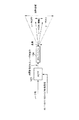
FIG. 11 shows the configuration of this conventional optical microscope. This optical microscope scans the sample 25 with a laser beam and visually observes the fluorescent images from the sample 25 and the
[0025]
In this operation, the laser light of a predetermined wavelength oscillated from the
[0026]
The fluorescence image generated from the sample 25 and the
[0027]
In the above-described operation, a part of the laser light from the
[0028]
In order to avoid such a problem, the
[0029]
Further, when the displacement detecting
[0030]
In order to avoid such a problem, a
[0031]
This conventional example is an example in which the SPM measurement using a cantilever can be simultaneously performed while improving the positioning accuracy of the cantilever and performing LSM fluorescence observation.
[0032]
[Problems to be solved by the invention]
In recent years, as research in the field of medical biology has progressed, there has been an increasing demand for observing and measuring a local ecological reaction of a living body observation sample by photostimulation. There are several techniques for imaging these phenomena using fluorescent signals. However, when observing at the atomic and molecular level, nano-level observation using AFM becomes essential.
[0033]
In JP-A-10-260190, a mercury lamp, a xenon lamp, or the like is used as an excitation light source. This is used as a light source for exciting a fluorescent substance attached to the probe, and is intended only to visualize the position of the probe. Therefore, an illumination optical system typified by Koehler illumination has a main purpose of irradiating a probe with light or irradiating the entire sample, and thus cannot be used as a microscope for observing a local photostimulation reaction of the sample. Further, even if the observation is performed by irradiating the entire sample, the applicable range of various reactions is narrow because the laser is not a laser having a high energy density for a target portion.
[0034]
In JP-A-8-304420, a laser is used as an excitation light source by combining an LSM optical system. However, this is also intended for use as a laser for observation, and since laser scanning is usually performed on the entire observation field of view, local irradiation is not performed. If local irradiation control is to be performed, it is not possible to realize high-precision position and area control for fine regions, accurate time control, and instantaneous switching of the irradiation light amount because the irradiation control of the carbano mirror alone is performed. Unwanted parts may be illuminated, making accurate observation impossible.
[0035]
An object of the present invention is to provide an atomic force and intermolecular force microscope capable of AFM observation of a response of a local portion of a biological sample to a light stimulus in order to respond to a demand for analyzing a phenomenon of molecular localization.
[0036]
[Means for Solving the Problems]
The atomic and intermolecular force microscope of the present invention, a cantilever having a probe at the tip, a displacement detecting means for optically detecting the displacement of the cantilever, a processing means for processing a detection signal obtained by the displacement detecting means, Scanning means for XYZ scanning the cantilever with respect to the sample, imaging means for obtaining an entire image of the sample, light source means for emitting a light beam for applying a light stimulus to the sample, and irradiation of the light beam from the light source means There are provided means for designating a position, a region, a light amount, and time, and control means for controlling a position, a region, a light amount, and a time of light beam irradiation from the light source unit.
[0037]
BEST MODE FOR CARRYING OUT THE INVENTION
Hereinafter, embodiments of the present invention will be described with reference to the drawings.
[0038]
First embodiment
The atomic and intermolecular force microscope according to the present embodiment will be described with reference to FIGS.
[0039]
As shown in FIG. 1, the atomic and intermolecular force microscope of the present embodiment is integrated with an
[0040]
The atomic and intermolecular force microscope further includes a
[0041]
The
[0042]
The
[0043]
The
[0044]
The atomic and intermolecular force microscope further includes an A /
[0045]
The
[0046]
The atomic and intermolecular force microscope has a
[0047]
Next, the operation of the atomic and intermolecular force microscope of the present embodiment will be described.
[0048]
In order to grasp the outline of the entire biological sample and to set the irradiation position and the like, the
[0049]
As the
[0050]
The focusing of the image is performed by the revolver
[0051]
As shown in FIG. 2A, when a desired image is obtained, a position in the sample to be irradiated with light is designated. As a designation method, for example, a position or an area is set from the
[0052]
When light of a plurality of wavelengths is used, the wavelength or the
[0053]
In addition, the irradiation intensity is selected and set. That is, a setting is made such that an arbitrary value from 0 to 100%, for example, 50% is selected as the irradiation intensity. Further, an irradiation time setting T1 such as how many seconds is performed is performed.
[0054]
These are set with the mouse while looking at screens such as images and selection menus. The setting software is controlled by the
[0055]
By such an operation, the irradiation position, area, time, and light amount parameter information are set. The
[0056]
When the start of irradiation is input from the
[0057]
Although this is a description of one-time scanning, it is important that the scanning speed is high when a high-speed phenomenon is desired to be observed or when irradiation is repeatedly performed many times. In such a case, AOM (Acousto-Optical Modulator) is often used. AOM is an acousto-optic modulation element, and similarly can scan the irradiation position of the laser beam at a high speed in response to the signal from the irradiation position /
[0058]
The control of the time and the light amount is performed by the light intensity /
[0059]
This will be described with reference to FIG. Control signals from the irradiation position /
[0060]
The laser light that has passed through the
[0061]
Further, as shown in FIG. 5, spatial irradiation can be performed by using, for example, the
[0062]
AFM observation is performed as described in the related art. In particular, this system observes and measures the behavior of ecology before and after the photoreaction, so the cantilever is set on the measurement part of the sample and the reaction before and after the laser irradiation is observed. For example, when force measurement is performed from a force curve, measurement is started before laser irradiation, that is, before reaction, and as shown in FIG. 6, a biological response after irradiation can be further observed. Further, since the irradiation timing signal is generated during the laser irradiation, the timing time during and after the irradiation can be known, and the progress of the reaction can be observed while comparing with time. FIG. 6 shows an example in which laser irradiation starts at time T1, ends at time T2, and some reaction occurs after time T2 to change the value of the intermolecular force.
[0063]
When observing the surface shape, an XYZ scan is performed using the
[0064]
Also, during the AFM observation, the fluorescence image and the transmission differential interference image of the sample can be simultaneously observed by the
[0065]
Also, a laser that emits light of a relatively long wavelength may be selected, in which case the laser light can be focused into the thick sample without scattering. As a result, a light stimulus can be applied to the deep part of the sample or the vicinity of the probe of the cantilever through the sample, and the reaction can be observed.
[0066]
Second embodiment
The atomic and intermolecular force microscope according to the present embodiment will be explained with reference to FIG. 7, the members indicated by the same reference numerals as the members shown in FIG. 1 are the same members, and the detailed description thereof will be omitted.
[0067]
The atomic and intermolecular force microscope of the present embodiment has a configuration in which a detection optical system for detecting fluorescence is added to the atomic and intermolecular force microscope of the first embodiment. The detection optical system is a confocal optical system, and can obtain a sharp observation image in the Z direction of the sample. Such an apparatus for observing a fluorescent image with a confocal optical microscope using a laser is called an LSM (Laser Scanning Microscope). A portion including the laser irradiation control and the detection portion is referred to as a
[0068]
The normal LSM image observation will be described. The position is adjusted to the noted Z position on the sample by the
[0069]
The fluorescence emitted from the sample returns to the
[0070]
The atomic and intermolecular force microscope of the present embodiment also has an optical system that can locally irradiate a laser similarly to the first embodiment. Therefore, as described above, after irradiating a desired portion with a laser, the laser is switched to a laser for image observation, and an LSM image of fluorescence image observation can be obtained simultaneously with AFM observation.
[0071]
As this application, a 3D image of an XYZ image can be constructed by acquiring a plurality of XY images at each Z position while moving the Z position in a desired step by the
[0072]
Further, the
[0073]
The
[0074]
Third embodiment
The atomic and intermolecular force microscope according to the present embodiment will be explained with reference to FIG. 8, the members denoted by the same reference numerals as those shown in FIG. 7 are the same members, and the detailed description thereof will be omitted.
[0075]
As shown in FIG. 8, the atomic and intermolecular force microscope of the present embodiment has a configuration in which a
[0076]
That is, the atomic and intermolecular force microscope of the present embodiment includes the
[0077]
By detecting the laser light emitted from the
[0078]
The light intensity /
[0079]
The irradiation area is not limited to the XY plane or the XYZ space, but may be an XZ plane, a YZ plane, or a straight line or a curve on an arbitrary plane.
[0080]
Further, these processes can be realized by both hardware and software.
[0081]
Although the embodiments of the present invention have been described with reference to the drawings, the present invention is not limited to these embodiments, and various modifications and changes may be made without departing from the spirit of the present invention. May be done.
[0082]
For example, in the above-described embodiment, a mouse is illustrated as the
[0083]
Further, the scanning mechanism is not limited to the
[0084]
【The invention's effect】
According to the atomic and intermolecular force microscope of the present invention, by irradiating a desired position and area of a sample with a light beam at a desired time and light intensity, a local portion of the sample generated in response to a light stimulus can be obtained. Various reactions can be observed by AFM.
[Brief description of the drawings]
FIG. 1 shows a configuration of an atomic and intermolecular force microscope according to a first embodiment of the present invention.
FIG. 2 shows an image obtained by an imaging unit in FIG. 1, an irradiation area set for the image, and a laser beam actually irradiated.
FIG. 3 shows a state where a laser beam is raster-scanned on a sample surface.
FIG. 4 shows a state of laser ON / OFF control for a minute area.
FIG. 5 shows a state in which laser light is spatially irradiated.
FIG. 6 shows the time control of laser ON / OFF and the temporal change of the intermolecular force value of the sample in response thereto.
FIG. 7 shows a configuration of an atomic and intermolecular force microscope according to a second embodiment of the present invention.
FIG. 8 shows a configuration of an atomic and intermolecular force microscope according to a third embodiment of the present invention.
FIG. 9 shows the overall configuration of a typical conventional AFM.
FIG. 10 shows an upper sensor A and a lower sensor B of the upper and lower split type PD in FIG. 9 and reflected light from the cantilever incident thereon.
FIG. 11 shows a configuration of an atomic force microscope apparatus using an inverted microscope disclosed in Japanese Patent Application Laid-Open No. 8-304420.
[Explanation of symbols]
100 Irradiation position / area control unit
101 Irradiation time control unit
102 Irradiation light amount controller
103 Light intensity / time designation section
104 Irradiation position / area designation section
105 laser
106 imaging unit
207 Cantilever
209 probe
213 XYZ scanner
221 Laser oscillator
230 Displacement detection unit
235 detector
255 display
257 CPU
262 Data processing unit
263 Z scan drive control unit
H.264 XY scanning drive control unit
270 Inverted microscope
Claims (3)
AFM観察のための探針を先端に備えるカンチレバーと、
カンチレバーの変位を光学的に検出する変位検出手段と、
変位検出手段で得られた検出信号を処理する処理手段と、
試料に対してカンチレバーをXYZ走査する走査手段と、
試料の全体像を得るための撮像手段と、
試料の局所的な部位に光刺激を与えるための光ビームを発する光源手段と、
光源手段からの光ビームの照射の位置と領域と光量と時間を指定する指定手段と、
光源手段からの光ビームの照射の位置と領域と光量と時間を制御する制御手段とを備えている、原子及び分子間力顕微鏡。Atom and intermolecular force microscope for AFM observation of a reaction of a local site of a biological sample to light stimulation,
A cantilever having a tip at the tip for AFM observation;
Displacement detection means for optically detecting the displacement of the cantilever;
Processing means for processing the detection signal obtained by the displacement detection means;
Scanning means for XYZ scanning the cantilever with respect to the sample;
Imaging means for obtaining an overall image of the sample;
Light source means for emitting a light beam for applying a light stimulus to a local portion of the sample,
Designation means for designating the position and area of light beam irradiation from the light source means, light quantity and time;
An atomic and intermolecular force microscope comprising a control unit for controlling a position and a region of light beam irradiation from a light source unit, a light amount and a time.
Priority Applications (1)
| Application Number | Priority Date | Filing Date | Title |
|---|---|---|---|
| JP2002227569A JP2004069428A (en) | 2002-08-05 | 2002-08-05 | Atomic force and molecular force microscope |
Applications Claiming Priority (1)
| Application Number | Priority Date | Filing Date | Title |
|---|---|---|---|
| JP2002227569A JP2004069428A (en) | 2002-08-05 | 2002-08-05 | Atomic force and molecular force microscope |
Publications (2)
| Publication Number | Publication Date |
|---|---|
| JP2004069428A true JP2004069428A (en) | 2004-03-04 |
| JP2004069428A5 JP2004069428A5 (en) | 2005-06-30 |
Family
ID=32014555
Family Applications (1)
| Application Number | Title | Priority Date | Filing Date |
|---|---|---|---|
| JP2002227569A Pending JP2004069428A (en) | 2002-08-05 | 2002-08-05 | Atomic force and molecular force microscope |
Country Status (1)
| Country | Link |
|---|---|
| JP (1) | JP2004069428A (en) |
Cited By (9)
| Publication number | Priority date | Publication date | Assignee | Title |
|---|---|---|---|---|
| JP2007500880A (en) * | 2003-05-16 | 2007-01-18 | ユニヴェルシテイト ファン アムステルダム | Method and apparatus for forming an image of an object |
| EP1760454A1 (en) * | 2004-06-24 | 2007-03-07 | Olympus Corporation | Fluorescent photometric device |
| WO2009157096A1 (en) * | 2008-06-27 | 2009-12-30 | Nippon Telegraph And Telephone Corporation | Stage for scanning probe microscopy and sample observation method |
| CN102331317A (en) * | 2011-06-02 | 2012-01-25 | 南京航空航天大学 | System and method for detection of micro-nano Newton force on spherical membrane vibratory quantum and application of method |
| CN103207035A (en) * | 2013-05-14 | 2013-07-17 | 曹毅 | Force spectrometer for measuring intermolecular forces |
| WO2013161545A1 (en) * | 2012-04-25 | 2013-10-31 | オリンパス株式会社 | Composite microscope combining scanning probe microscope and optical microscope; control device, control method, and control program therefor; and recording medium |
| WO2017145381A1 (en) * | 2016-02-26 | 2017-08-31 | オリンパス株式会社 | Observation method using compound microscope having inverted optical microscope and atomic force microscope, and program and compound microscope for carrying out observation method |
| CN110132923A (en) * | 2019-05-31 | 2019-08-16 | 中国科学院长春应用化学研究所 | The controllable tracer super-resolution micro imaging method of Structured Illumination |
| JPWO2021187383A1 (en) * | 2020-03-14 | 2021-09-23 |
-
2002
- 2002-08-05 JP JP2002227569A patent/JP2004069428A/en active Pending
Cited By (17)
| Publication number | Priority date | Publication date | Assignee | Title |
|---|---|---|---|---|
| JP2007500880A (en) * | 2003-05-16 | 2007-01-18 | ユニヴェルシテイト ファン アムステルダム | Method and apparatus for forming an image of an object |
| EP1760454A1 (en) * | 2004-06-24 | 2007-03-07 | Olympus Corporation | Fluorescent photometric device |
| EP1760454A4 (en) * | 2004-06-24 | 2008-09-03 | Olympus Corp | Fluorescent photometric apparatus |
| US8418261B2 (en) | 2008-06-27 | 2013-04-09 | Nippon Telegraph And Telephone Corporation | Stage for scanning probe microscopy and sample observation method |
| GB2473368A (en) * | 2008-06-27 | 2011-03-09 | Nippon Telegraph & Telephone | Stage for scanning probe microscopy and sample observation method |
| JP2011521202A (en) * | 2008-06-27 | 2011-07-21 | 日本電信電話株式会社 | Scanning probe microscope stage and sample observation method |
| GB2473368B (en) * | 2008-06-27 | 2012-09-19 | Nippon Telegraph & Telephone | Stage for scanning probe microscopy and sample observation method |
| WO2009157096A1 (en) * | 2008-06-27 | 2009-12-30 | Nippon Telegraph And Telephone Corporation | Stage for scanning probe microscopy and sample observation method |
| CN102331317A (en) * | 2011-06-02 | 2012-01-25 | 南京航空航天大学 | System and method for detection of micro-nano Newton force on spherical membrane vibratory quantum and application of method |
| WO2013161545A1 (en) * | 2012-04-25 | 2013-10-31 | オリンパス株式会社 | Composite microscope combining scanning probe microscope and optical microscope; control device, control method, and control program therefor; and recording medium |
| EP2843422A4 (en) * | 2012-04-25 | 2015-05-13 | Olympus Corp | Composite microscope combining scanning probe microscope and optical microscope; control device, control method, and control program therefor; and recording medium |
| CN103207035A (en) * | 2013-05-14 | 2013-07-17 | 曹毅 | Force spectrometer for measuring intermolecular forces |
| CN103207035B (en) * | 2013-05-14 | 2015-07-15 | 南京因艾生生物科技有限公司 | Force spectrometer for measuring intermolecular forces |
| WO2017145381A1 (en) * | 2016-02-26 | 2017-08-31 | オリンパス株式会社 | Observation method using compound microscope having inverted optical microscope and atomic force microscope, and program and compound microscope for carrying out observation method |
| JPWO2017145381A1 (en) * | 2016-02-26 | 2018-12-13 | オリンパス株式会社 | Observation method using a composite microscope having an inverted optical microscope and an atomic force microscope, a program for executing the observation method, and a composite microscope |
| CN110132923A (en) * | 2019-05-31 | 2019-08-16 | 中国科学院长春应用化学研究所 | The controllable tracer super-resolution micro imaging method of Structured Illumination |
| JPWO2021187383A1 (en) * | 2020-03-14 | 2021-09-23 |
Similar Documents
| Publication | Publication Date | Title |
|---|---|---|
| JP5687201B2 (en) | Combined microscopy | |
| US10690898B2 (en) | Light-field microscope with selective-plane illumination | |
| US7218446B2 (en) | Imaging system having a fine focus | |
| JP5354938B2 (en) | Fluorescence microscope device | |
| JP5097247B2 (en) | Confocal microscope apparatus and observation method using confocal microscope apparatus | |
| US8450703B2 (en) | Method and system for imaging samples | |
| JP2010505094A (en) | Luminescence microscopy with increased resolution | |
| JP4932076B2 (en) | Scanning laser microscope | |
| JP2002082287A (en) | Apparatus and method for inspection and operation of object for microscope | |
| JP4414722B2 (en) | Laser microscope | |
| JP2007114542A (en) | Microscope observation apparatus and microscope observation method | |
| JP2015504177A (en) | Nonlinear optical microscope for quantitative determination using shaped beam | |
| JP2004069428A (en) | Atomic force and molecular force microscope | |
| JP2003195172A (en) | Scanning laser microscope | |
| JP2003195174A (en) | Scanning laser microscope system | |
| JP2008114059A (en) | Laser beam processing device, and laser beam processing method | |
| CN107490566A (en) | Airy beam mating plate illumination microscopic imaging device based on binary optical elements | |
| Temprine et al. | Three-dimensional photoactivated localization microscopy with genetically expressed probes | |
| KR101080382B1 (en) | Confocal laser scanning microscope | |
| JP3968629B2 (en) | Fluorescence image measuring device | |
| JP4722464B2 (en) | Total reflection fluorescent lighting device | |
| JP2004069428A5 (en) | ||
| JP4602731B2 (en) | Microscope system | |
| CN209847146U (en) | Multi-modal imaging system | |
| JP2010266452A (en) | Scanning optical near-field microscope |
Legal Events
| Date | Code | Title | Description |
|---|---|---|---|
| A521 | Written amendment |
Effective date: 20041013 Free format text: JAPANESE INTERMEDIATE CODE: A523 |
|
| A621 | Written request for application examination |
Effective date: 20041013 Free format text: JAPANESE INTERMEDIATE CODE: A621 |
|
| A131 | Notification of reasons for refusal |
Effective date: 20071030 Free format text: JAPANESE INTERMEDIATE CODE: A131 |
|
| A521 | Written amendment |
Free format text: JAPANESE INTERMEDIATE CODE: A523 Effective date: 20071220 |
|
| A131 | Notification of reasons for refusal |
Effective date: 20080909 Free format text: JAPANESE INTERMEDIATE CODE: A131 |
|
| A02 | Decision of refusal |
Free format text: JAPANESE INTERMEDIATE CODE: A02 Effective date: 20090210 |