JP2004067006A - Structure of hood lock striker - Google Patents
Structure of hood lock striker Download PDFInfo
- Publication number
- JP2004067006A JP2004067006A JP2002231018A JP2002231018A JP2004067006A JP 2004067006 A JP2004067006 A JP 2004067006A JP 2002231018 A JP2002231018 A JP 2002231018A JP 2002231018 A JP2002231018 A JP 2002231018A JP 2004067006 A JP2004067006 A JP 2004067006A
- Authority
- JP
- Japan
- Prior art keywords
- striker
- hood
- lock
- vehicle
- bolt
- Prior art date
- Legal status (The legal status is an assumption and is not a legal conclusion. Google has not performed a legal analysis and makes no representation as to the accuracy of the status listed.)
- Granted
Links
- 230000035939 shock Effects 0.000 abstract 1
- 230000000694 effects Effects 0.000 description 3
- 238000003466 welding Methods 0.000 description 2
- 230000007423 decrease Effects 0.000 description 1
- 238000009751 slip forming Methods 0.000 description 1
Images

Classifications
-
- E—FIXED CONSTRUCTIONS
- E05—LOCKS; KEYS; WINDOW OR DOOR FITTINGS; SAFES
- E05B—LOCKS; ACCESSORIES THEREFOR; HANDCUFFS
- E05B77/00—Vehicle locks characterised by special functions or purposes
- E05B77/02—Vehicle locks characterised by special functions or purposes for accident situations
- E05B77/08—Arrangements for protection of pedestrians
-
- B—PERFORMING OPERATIONS; TRANSPORTING
- B60—VEHICLES IN GENERAL
- B60R—VEHICLES, VEHICLE FITTINGS, OR VEHICLE PARTS, NOT OTHERWISE PROVIDED FOR
- B60R21/00—Arrangements or fittings on vehicles for protecting or preventing injuries to occupants or pedestrians in case of accidents or other traffic risks
- B60R21/34—Protecting non-occupants of a vehicle, e.g. pedestrians
-
- E—FIXED CONSTRUCTIONS
- E05—LOCKS; KEYS; WINDOW OR DOOR FITTINGS; SAFES
- E05B—LOCKS; ACCESSORIES THEREFOR; HANDCUFFS
- E05B85/00—Details of vehicle locks not provided for in groups E05B77/00 - E05B83/00
- E05B85/04—Strikers
- E05B85/045—Strikers for bifurcated bolts
-
- B—PERFORMING OPERATIONS; TRANSPORTING
- B60—VEHICLES IN GENERAL
- B60R—VEHICLES, VEHICLE FITTINGS, OR VEHICLE PARTS, NOT OTHERWISE PROVIDED FOR
- B60R21/00—Arrangements or fittings on vehicles for protecting or preventing injuries to occupants or pedestrians in case of accidents or other traffic risks
- B60R21/34—Protecting non-occupants of a vehicle, e.g. pedestrians
- B60R2021/343—Protecting non-occupants of a vehicle, e.g. pedestrians using deformable body panel, bodywork or components
-
- E—FIXED CONSTRUCTIONS
- E05—LOCKS; KEYS; WINDOW OR DOOR FITTINGS; SAFES
- E05B—LOCKS; ACCESSORIES THEREFOR; HANDCUFFS
- E05B83/00—Vehicle locks specially adapted for particular types of wing or vehicle
- E05B83/16—Locks for luggage compartments, car boot lids or car bonnets
- E05B83/24—Locks for luggage compartments, car boot lids or car bonnets for car bonnets
Landscapes
- Engineering & Computer Science (AREA)
- Mechanical Engineering (AREA)
- Superstructure Of Vehicle (AREA)
Abstract
Description
【0001】
【発明の属する技術分野】
本願発明は、フードを車体に固定するためのフードロックストライカ構造に関する。
【0002】
【従来の技術】
図9は、従来のフードロックストライカ構造の一例を示している。図示されたフードロックストライカ構造は、車体構造部材に設けられているロック103と係合するロッド101が溶接等によって平板状のブラケット102に固定されており、このブラケット102がフード104のフードインナパネル104aに取り付けられた形態を有している。より具体的には、ロッド101は、車両高さ方向に延びる一対の鉛直部101aと、これらを繋ぐ水平部101bと、を有する略U字状に形成されている。ブラケット102は、一対の鉛直部101aが車両前後方向に並ぶようにして、フードインナパネル104aに取り付けられている。ロック103と水平部101bとが係合することによって、フード104は車体に固定される。
【0003】
このようなフード104と車体との固定は、たとえば車両の走行中に解除されるようなことがあってはならない。そのため、ロッド101は、車両の走行中にフード104が受ける風圧やロック103との接触などによって変形を生じたりすることがないように、その径を大きくするなどして強度が大きくされている。
【0004】
【発明が解決しようとする課題】
しかしながら、上記従来の構造においては、次のような不具合があった。
【0005】
すなわち、従来において、ロッド101は、それ自身の強度が大きい上に、フードインナパネル104aに対して垂直に取り付けられているため、その上方からの負荷に対して変形し難くなっている。したがって、たとえば車両が歩行者に対して前方衝突した際に、この歩行者がロッド101を含む車両前方部分の上方に接触した場合において、上記従来の構造では、接触時の衝撃を十分に吸収することができず、歩行者に大きな衝撃を与えてしまう。
【0006】
本願発明は、このような事情のもとで考え出されたものであって、車両が歩行者に対して前方衝突等を行なった場合に、この歩行者に与える衝撃を小さくすることができるようにしたフードロックストライカ構造を提供することをその課題としている。
【0007】
【発明の開示】
上記の課題を解決するために、本願発明では、次の技術的手段を講じている。
【0008】
本願発明によって提供されるフードロックストライカ構造は、フードに取り付けられているストライカが、車体構造部材に設けられているロックと係合するフードロックストライカ構造であって、上記ストライカは、その上方から所定値以上の負荷入力があったときに、このストライカを車両高さ方向に小さくするような変形をする変形容易部を有していることを特徴としている。
【0009】
車両が歩行者に対して前方衝突等を行なった際に、この歩行者が上記ストライカを含む車両前方部分の上方と接触し、上記ストライカがその上方から所定値以上の負荷を受ける場合がある。このような場合において、本願発明では、上記ストライカに対し、このストライカを車両高さ方向に小さくするような変形をする上記変形容易部を設けている。そのため、歩行者が上記車両前方部分の上方と接触したときに受ける衝撃を上記変形容易部の変形によって吸収し、歩行者に与える衝撃を小さくすることができる。
【0010】
本願発明の好ましい実施の形態においては、上記ストライカは、上記ロックと係合する係合部と、この係合部から対をなして略V字を形成するように斜め上方に向かって延び、かつその先端部が上記フードに取り付けられている傾斜部と、を有している。
【0011】
このような構成によれば、車両が歩行者に対して前方衝突等を行なったことによって、上記ストライカにその上方から所定値以上の負荷入力があった場合に、上記ストライカは、上記先端部どうしが離反するような変形、つまり車両高さ方向に小さくなるような変形をすることができる。そのため、上記したような衝撃吸収機能を発揮することできる。
【0012】
本願発明の好ましい実施の形態においては、上記ストライカは、上記先端部に形成された貫通孔を通したボルトを介して上記フードに固定されており、上記フードには、ボルト通し孔と、このボルト通し孔から上記先端部どうしが離反していく方向に延び、かつ上記ボルトの軸部の径よりも小さい幅を有するスリットと、が形成されている。
【0013】
このような構成によれば、上記ストライカがその上方から所定値以上の負荷を受けた場合には、上記先端部の移動方向に上記スリットが設けられているため、上記ボルトの固定力が解除された後に、上記ストライカは車両高さ方向に小さくなるような変形をより容易に行なうことができる。また、上記した構成によれば、上記スリットの幅は、上記ボルトの軸部の径よりも小さくされているため、上記ストライカは、上記スリットを割き拡げながら変形をする。つまり、上記負荷を受けた際の衝撃エネルギの一部が、上記スリットを割き拡げる力に変換されることとなる。そのため、スリットの幅が上記ボルトの軸部の径以上である場合と比べて、上記負荷を受けた際の衝撃をより多く吸収することができる。
【0014】
本願発明の好ましい実施の形態においては、上記フードは、上記スリットに連続する開口部を有しており、この開口部は、上記ストライカの上方から所定値以上の負荷入力があったときに、上記先端部が上記フードから離脱可能なように形成されている。
【0015】
このような構成によれば、上記ストライカがその上方から所定値以上の負荷を受けた場合に、上記ストライカは、上記スリットを割き拡げながら変形をした後、上記先端部が上記開口部に達することにより、上記フードから離脱することができる。このことよって、上記負荷を受けた際の衝撃をより多く吸収することが可能となる。
【0016】
本願発明の好ましい実施の形態においては、上記ストライカは、上記ロックと係合する係合部材と、先端部が上記フードに取り付けられ、かつ上記係合部材が固着される固着部材と、を備えており、上記係合部材および上記固着部材の少なくとも一方が筒状の部材であって、これらの上方から所定値以上の負荷入力があったときに、車両高さ方向に小さくなるようなスライドが可能なように、上記筒状の部材に他方の部材が嵌合している。
【0017】
このような構成においても、車両が歩行者に対して前方衝突等を行なったことによって、上記ストライカにその上方から所定値以上の負荷入力があった場合に、上記ストライカは、上記筒状の部材および上記他方の部材が上記したスライドをすることにより、車両高さ方向に小さくなることができる。したがって、上記した前方衝突時に歩行者が受ける衝撃を吸収し、歩行者に与える衝撃を小さくすることができる。
【0018】
本願発明のその他の特徴および利点については、以下に行う発明の実施の形態の説明から、より明らかになるであろう。
【0019】
【発明の実施の形態】
以下、本願発明の好ましい実施の形態について、図面を参照しつつ具体的に説明する。
【0020】
図1および図2は、本願発明に係る第1の実施形態を示している。図1以降の図において、矢印Frは車両前方を示し、矢印Upは車両上方を示している。
【0021】
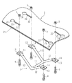
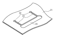
図示されたフードロックストライカ構造は、フード2のフードインナパネル21の前部にボルト4およびナット5を介して取り付けられているストライカ1が、ラジエータサポート(図示略)に設けられているロック3と係合するように構成されている。
【0022】
ストライカ1は、フード2を車体に固定するために利用されるものであり、ロック3と係合する係合部11を有している。この係合部11は、車両前後方向に延びており、その両端部からは、一対の傾斜部12が正面視において略V字を形成するようにして車幅方向の斜め上方に向かって延出している。各傾斜部12の先端部13は、ボルト4挿通用の貫通孔14を有する略平板状となっており、フードインナパネル21に当接している。
【0023】
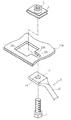
フードインナパネル21には、各傾斜部12の先端部13に形成されている貫通孔14と同軸上となるように、ボルト通し孔22が形成されている。これらのボルト通し孔22には、車幅方向の車両外側に向かって延びるスリット23の一端が連続しており、これらのスリット23の他端には、開口部24が連続している。各スリット23の幅は、ボルト4の軸部の径よりも小さくされている。各開口部24のサイズは、ナット5のサイズよりも大きくされている。
【0024】
ストライカ1は、各傾斜部12の先端部13がフードインナパネル21に当接した状態において、たとえば各貫通孔14および各ボルト通し孔22を通したボルト4をフードインナパネル21の裏面側に取り付けられたナット5にねじ込むことによって、フード2に固定される。
【0025】
次に、上記構成のフードロックストライカ構造の作用について説明する。
【0026】
通常時においては、たとえばフード2を車体に押し付ける操作によって、ストライカ1とロック3とが係合し、フード2が車体に固定される。上記した操作等によって、ストライカ1およびロック3が変形するようなことはなく、適正な固定状態が維持される。なお、フード2と車体との固定は、たとえば車室に設けられているリリースノブ(図示略)を手前に引くこと等により、解除されるようになっている。
【0027】
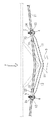
一方、車両が歩行者に対して前方衝突等を行なったような非常時においては、歩行者がストライカ1を含む車両前方部分の上方に接触する場合があり、このとき、ストライカ1は、その上方から大きな負荷Fを受ける。このストライカ1と係合しているロック3が取り付けられている上記ラジエータサポートは、剛性が大きい部材であるため、負荷Fによって下方へ大きく移動することはない。これに対し、ストライカ1は、上述したように、係合部11の両端部から車幅方向の斜め上方に延出している傾斜部12を有している。そのため、ストライカ1は、負荷Fによって、上記ラジエータサポートに押圧され、傾斜部12の先端部13には、車幅方向の車両外側に向いた力が作用する。このような力により、ボルト4の固定力は解除され、ストライカ1は、図3の実線に示されているように、先端部13がボルト4およびナット5を引き連れながら車幅方向の車両外側に移動するような変形、つまり車両高さ方向に小さくなるような変形をする。
【0028】
フードインナパネル21には、ボルト通し孔22から先端部13の移動方向に延びるスリット23が形成されているため、上記したストライカ1の変形は容易に行われる。なお、スリット23の幅はボルト4の軸部の径よりも小さいため、ボルト4は、このスリット23を割き拡げながら移動することとなる。その後、先端部13がスリット23に連続している開口部24に達すると、開口部24はナット5よりも大きなサイズとなっているため、ナット5が開口部24から脱落し、このことによって、ストライカ1はフード2から離脱する。
【0029】
このようなストライカ1の変形によって、上記した歩行者と車両前方部分の上方との接触時における衝撃は吸収されることとなる。また、スリット23が割き拡げられることやストライカ1がフード2から離脱することによって、衝撃はさらに吸収される。したがって、このようなフードロックストライカ構造によれば、上記した接触時に歩行者に与える衝撃を小さくすることができる。
【0030】
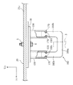
図4は、本願発明の第2の実施形態を示している。この実施形態では、ストライカの形状が上記した第1の実施形態と異なる。このストライカの構造について、次に説明する。なお、図4以降の図において、第1の実施形態と同一または類似の要素には第1の実施形態と同一の符号を付している。
【0031】
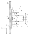
ストライカ10は、フードインナパネル21aにボルト4を介して固定されている略平板状のブラケット18に対して、略円筒状であり、かつ車両前後方向に間隔を隔てて取り付けられている一対の固着部材15に、水平部16aおよび一対の鉛直部16bを有する略U字状の係合部材16が固着された形状となっている。より具体的には、各固着部材15は、車両高さ方向に十分に延びており、内側の所望の位置には突起17が設けられている。このような各固着部材15の内部に各鉛直部16bの上部が嵌合し、かつ各突起17に当接した状態において、係合部材16は各固着部材15に溶接等によって固着されている。このようなストライカ10の水平部16aとロック3とが係合することによって、フード20は車体に固定されることとなる。なお、通常時におけるフード20の開閉操作等によって、係合部材16と各固着部材15との固着状態が解除されることはなく、また、各突起17も圧しつぶされるようなことはない。
【0032】
以上の構成においても、上記第1の実施形態について説明したのと同様の作用効果を期待することができる。すなわち、車両が歩行者に対して前方衝突等を行なったことによって、歩行者がストライカ10を含む車両前方部分の上方に接触し、ストライカ10がその上方から所定値以上の負荷Fを受けた場合には、各固着部材15と係合部材16との固着状態が解除されるとともに、各突起17が圧しつぶされて、図5に示されているように、各鉛直部16bが各固着部材15の基端部側へさらに挿入される。つまり、ストライカ10は、車両高さ方向に小さくなるような変形をすることとなる。このようなストライカ10の変形により、上記した接触時の衝撃は吸収されるため、歩行者に与える衝撃を小さくすることができる。
【0033】
もちろん、本願発明は、上述した実施形態の内容に限定されるものではない。たとえば、上記第1の実施形態において、車両前後方向に並んでいる開口部24は、図6に示されているように、車両前後方向に連続していてもよい。このようにすれば、ストライカ1はより確実にフードから離脱することができるようになる。また、ストライカは、係合部が車幅方向に延び、かつ一対の傾斜部が側面視において略V字を形成するように、フードに取り付けられてもよい。このような構成であっても、ストライカは、その上方から負荷入力があった場合に、車両高さ方向に小さくなるような変形をすることができる。
【0034】
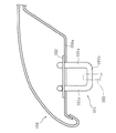
上記第1の実施形態におけるストライカは、図7に示されているようにして、フードインナパネル21bに取り付けられてもよい。すなわち、ボルト通し孔22b、スリット23b、および開口部24bが連続して形成されているフードインナパネル21bに対して、座金と同様な役割を果たす断面略コ字状のアタッチメント6をボルト通し孔22bおよびスリット23bを覆うようにして取り付けたうえで、ストライカ1をフードインナパネル21bにボルト4を介して固定してもよい。開口部24bのサイズは、アタッチメント6のサイズよりも大きくされている。このような構成によれば、通常時において、ストライカ1がフードインナパネル21bに固定されている状態をより確実に維持することができる。一方、ストライカ1の上方から所定値以上の負荷入力があった場合には、ボルト4の固定力が解除されて、ストライカ1の先端部13がスムーズに車幅方向の車両外側に移動し、アタッチメント6とともに先端部13がフードインナパネル21bから脱落することとなる。したがって、上記第1の実施形態と同様の効果を期待することができる。
【0035】
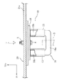
上記第2の実施形態におけるストライカは、図8に示されているような構造であってもよい。図示されたストライカの構造は、先端に折り曲げ部170が形成されている固着部材150と、鉛直部160bに凹部160cが形成されている係合部材160と、を有している。折り曲げ部170は、凹部160cに嵌合しており、このことによって、係合部材160は固着部材150に固着されている。このような構成においても、折り曲げ部170等の強度設定を適正に行なうことによって、上記第2の実施形態と同様の作用効果を得ることができる。その他、本願発明に係るフードロックストライカ構造の各部の具体的な構成についても、種々に設計変更自在である。
【図面の簡単な説明】
【図1】本願発明の第1の実施形態に係るフードロックストライカ構造の一例を示す概略側面図である。
【図2】図1に示すフードロックストライカ構造の概略斜視図である。
【図3】図1に示すフードロックストライカ構造の作用説明図である。
【図4】本願発明の第2の実施形態に係るフードロックストライカ構造の一例を示す概略断面図である。
【図5】図4に示すフードロックストライカ構造の作用説明図である。
【図6】図1のフードロックストライカ構造の他の例を示す概略要部斜視図である。
【図7】図1のフードロックストライカ構造の他の例を示す概略要部斜視図である。
【図8】図4のフードロックストライカ構造の他の例を示す概略断面図である。
【図9】従来のフードロックストライカ構造の一例を示す概略側面図である。
【符号の説明】
1,10 ストライカ
2 フード
3 ロック
4 ボルト
11 係合部
12 傾斜部
13 先端部
15 固着部材
16 係合部材
22 ボルト通し孔
23 スリット
24 開口部[0001]
TECHNICAL FIELD OF THE INVENTION
The present invention relates to a hood lock striker structure for fixing a hood to a vehicle body.
[0002]
[Prior art]
FIG. 9 shows an example of a conventional hood lock striker structure. In the illustrated hood lock striker structure, a
[0003]
Such fixing between the
[0004]
[Problems to be solved by the invention]
However, the above conventional structure has the following disadvantages.
[0005]
That is, in the related art, since the
[0006]
The present invention has been conceived under such circumstances, and it is possible to reduce the impact given to a pedestrian when the vehicle makes a forward collision with the pedestrian. It is an object of the present invention to provide a hood lock striker structure.
[0007]
DISCLOSURE OF THE INVENTION
In order to solve the above problems, the present invention takes the following technical measures.
[0008]
The hood lock striker structure provided by the present invention is a hood lock striker structure in which a striker attached to a hood is engaged with a lock provided on a vehicle body structural member, and the striker is a predetermined type from above. It is characterized in that it has an easily deformable portion that deforms to reduce the striker in the vehicle height direction when a load input exceeding the value is received.
[0009]
When the vehicle makes a forward collision with the pedestrian or the like, the pedestrian may come into contact with the upper part of the front part of the vehicle including the striker, and the striker may receive a load of a predetermined value or more from above. In such a case, in the present invention, the above-mentioned striker is provided with the above-mentioned easily deformable portion which is deformed so as to make the striker smaller in the vehicle height direction. Therefore, the impact received when the pedestrian comes into contact with the upper part of the front part of the vehicle is absorbed by the deformation of the easily deformable portion, and the impact given to the pedestrian can be reduced.
[0010]
In a preferred embodiment of the present invention, the striker extends obliquely upward so as to form a substantially V-shape as a pair with an engagement portion that engages with the lock, and A tip portion having an inclined portion attached to the hood.
[0011]
According to such a configuration, when the vehicle strikes the pedestrian in a forward collision or the like, and the striker receives a load input that is equal to or more than a predetermined value from above the striker, the striker connects the tip ends to each other. Can be deformed so as to separate from each other, that is, can be reduced in the vehicle height direction. Therefore, the impact absorbing function as described above can be exhibited.
[0012]
In a preferred embodiment of the present invention, the striker is fixed to the hood via a bolt passing through a through-hole formed at the tip, and the hood has a bolt through hole, A slit extending in a direction in which the tip portions move away from the through hole and having a width smaller than a diameter of a shaft portion of the bolt.
[0013]
According to such a configuration, when the striker receives a load equal to or more than a predetermined value from above, since the slit is provided in the moving direction of the distal end, the fixing force of the bolt is released. After that, the striker can be more easily deformed so as to become smaller in the vehicle height direction. Further, according to the above configuration, since the width of the slit is smaller than the diameter of the shaft portion of the bolt, the striker deforms while splitting and expanding the slit. In other words, a part of the impact energy when receiving the load is converted into a force for splitting and expanding the slit. Therefore, compared to the case where the width of the slit is equal to or larger than the diameter of the shaft portion of the bolt, it is possible to absorb more impact when the load is received.
[0014]
In a preferred embodiment of the present invention, the hood has an opening continuous with the slit, and the opening is provided when a load input of a predetermined value or more is received from above the striker. The tip is formed so as to be detachable from the hood.
[0015]
According to such a configuration, when the striker receives a load equal to or more than a predetermined value from above, the striker deforms while splitting and expanding the slit, and then the tip portion reaches the opening. Thereby, the hood can be separated from the hood. This makes it possible to absorb more impact when receiving the load.
[0016]
In a preferred embodiment of the present invention, the striker includes: an engaging member that engages with the lock; and a fixing member having a distal end attached to the hood and to which the engaging member is fixed. In addition, at least one of the engaging member and the fixing member is a cylindrical member, and when a load of a predetermined value or more is input from above the member, the sliding member can slide in the vehicle height direction. Thus, the other member is fitted to the cylindrical member.
[0017]
Even in such a configuration, when the vehicle strikes the pedestrian in a forward collision or the like, and the striker receives a load input that is equal to or more than a predetermined value from above the striker, the striker is configured as the cylindrical member. And, the other member slides as described above, so that it can be reduced in the vehicle height direction. Therefore, the impact given to the pedestrian at the time of the above-mentioned forward collision can be absorbed, and the impact given to the pedestrian can be reduced.
[0018]
Other features and advantages of the present invention will become more apparent from the following description of embodiments of the present invention.
[0019]
BEST MODE FOR CARRYING OUT THE INVENTION
Hereinafter, preferred embodiments of the present invention will be specifically described with reference to the drawings.
[0020]
1 and 2 show a first embodiment according to the present invention. In the drawings after FIG. 1, the arrow Fr indicates the front of the vehicle, and the arrow Up indicates the upper side of the vehicle.
[0021]
In the illustrated hood lock striker structure, a striker 1 attached to a front portion of a hood
[0022]
The striker 1 is used for fixing the
[0023]
A bolt through
[0024]
The striker 1 attaches, for example, the
[0025]
Next, the operation of the hood lock striker structure having the above configuration will be described.
[0026]
In a normal state, for example, by pressing the
[0027]
On the other hand, in an emergency such as when the vehicle has collided forward with the pedestrian, the pedestrian may come into contact with a portion above the front portion of the vehicle including the striker 1, and at this time, the striker 1 From a large load F. Since the radiator support to which the lock 3 engaged with the striker 1 is attached is a member having high rigidity, the radiator support does not largely move downward due to the load F. On the other hand, the striker 1 has the inclined
[0028]
Since the hood
[0029]
Due to such deformation of the striker 1, the impact at the time of the contact between the pedestrian and the upper part of the front part of the vehicle is absorbed. Further, the impact is further absorbed by the
[0030]
FIG. 4 shows a second embodiment of the present invention. In this embodiment, the shape of the striker is different from that of the first embodiment. Next, the structure of this striker will be described. Note that, in FIG. 4 and subsequent drawings, the same or similar elements as in the first embodiment are denoted by the same reference numerals as in the first embodiment.
[0031]
The
[0032]
Also in the above configuration, the same operation and effect as described in the first embodiment can be expected. That is, when the vehicle makes a forward collision or the like with the pedestrian, the pedestrian comes into contact with a portion above the vehicle front portion including the
[0033]
Of course, the present invention is not limited to the contents of the above-described embodiment. For example, in the first embodiment, the
[0034]
The striker in the first embodiment may be attached to the hood
[0035]
The striker in the second embodiment may have a structure as shown in FIG. The structure of the illustrated striker has a fixing
[Brief description of the drawings]
FIG. 1 is a schematic side view showing an example of a hood lock striker structure according to a first embodiment of the present invention.
FIG. 2 is a schematic perspective view of the hood lock striker structure shown in FIG.
FIG. 3 is an operation explanatory view of the hood lock striker structure shown in FIG. 1;
FIG. 4 is a schematic sectional view showing an example of a hood lock striker structure according to a second embodiment of the present invention.
FIG. 5 is an operation explanatory view of the hood lock striker structure shown in FIG. 4;
FIG. 6 is a schematic perspective view showing another example of the hood lock striker structure of FIG. 1;
FIG. 7 is a schematic perspective view showing another example of the hood lock striker structure of FIG. 1;
8 is a schematic sectional view showing another example of the hood lock striker structure of FIG.
FIG. 9 is a schematic side view showing an example of a conventional hood lock striker structure.
[Explanation of symbols]
1, 10
Claims (5)
上記ストライカは、その上方から所定値以上の負荷入力があったときに、このストライカを車両高さ方向に小さくするような変形をする変形容易部を有していることを特徴とする、フードロックストライカ構造。A striker attached to the hood has a hood lock striker structure that engages with a lock provided on the vehicle body structural member,
A hood lock, characterized in that the striker has an easy-to-deform portion that deforms the striker in a vehicle height direction when a load input of a predetermined value or more is input from above the striker. Striker structure.
上記フードには、ボルト通し孔と、このボルト通し孔から上記先端部どうしが離反していく方向に延び、かつ上記ボルトの軸部の径よりも小さい幅を有するスリットと、が形成されている、請求項2に記載のフードロックストライカ構造。The striker is fixed to the hood via a bolt passing through a through hole formed in the tip,
The hood is formed with a bolt passage hole and a slit extending in a direction in which the tip portions move away from the bolt passage hole and having a width smaller than a diameter of a shaft portion of the bolt. The hood lock striker structure according to claim 2.
上記係合部材および上記固着部材の少なくとも一方が筒状の部材であって、これらの上方から所定値以上の負荷入力があったときに、車両高さ方向に小さくなるようなスライドが可能なように、上記筒状の部材に他方の部材が嵌合している、請求項1に記載のフードロックストライカ構造。The striker includes: an engaging member that engages with the lock; and a fixing member having a distal end attached to the hood and to which the engaging member is fixed.
At least one of the engaging member and the fixing member is a cylindrical member, and when a load input of a predetermined value or more is received from above the member, the sliding can be performed such that the sliding becomes smaller in the vehicle height direction. The hood lock striker structure according to claim 1, wherein the other member is fitted to the cylindrical member.
Priority Applications (5)
| Application Number | Priority Date | Filing Date | Title |
|---|---|---|---|
| JP2002231018A JP4021723B2 (en) | 2002-08-08 | 2002-08-08 | Hood lock striker structure |
| DE60327348T DE60327348D1 (en) | 2002-08-08 | 2003-08-07 | CLOSING PLATE FOR A HOOD LOCK |
| PCT/JP2003/010099 WO2004014714A1 (en) | 2002-08-08 | 2003-08-07 | Hood lock striker |
| AU2003254881A AU2003254881A1 (en) | 2002-08-08 | 2003-08-07 | Hood lock striker |
| EP03784591A EP1557340B1 (en) | 2002-08-08 | 2003-08-07 | Hood lock striker |
Applications Claiming Priority (1)
| Application Number | Priority Date | Filing Date | Title |
|---|---|---|---|
| JP2002231018A JP4021723B2 (en) | 2002-08-08 | 2002-08-08 | Hood lock striker structure |
Publications (2)
| Publication Number | Publication Date |
|---|---|
| JP2004067006A true JP2004067006A (en) | 2004-03-04 |
| JP4021723B2 JP4021723B2 (en) | 2007-12-12 |
Family
ID=31711731
Family Applications (1)
| Application Number | Title | Priority Date | Filing Date |
|---|---|---|---|
| JP2002231018A Expired - Lifetime JP4021723B2 (en) | 2002-08-08 | 2002-08-08 | Hood lock striker structure |
Country Status (5)
| Country | Link |
|---|---|
| EP (1) | EP1557340B1 (en) |
| JP (1) | JP4021723B2 (en) |
| AU (1) | AU2003254881A1 (en) |
| DE (1) | DE60327348D1 (en) |
| WO (1) | WO2004014714A1 (en) |
Cited By (7)
| Publication number | Priority date | Publication date | Assignee | Title |
|---|---|---|---|---|
| JP2006096280A (en) * | 2004-09-30 | 2006-04-13 | Mazda Motor Corp | Hood stopper structure of automobile |
| JP2006096255A (en) * | 2004-09-30 | 2006-04-13 | Mazda Motor Corp | Hood stopper structure of automobile |
| JP2006199179A (en) * | 2005-01-21 | 2006-08-03 | Honda Motor Co Ltd | Vehicle hood device |
| KR100872940B1 (en) * | 2007-11-13 | 2008-12-08 | 현대자동차주식회사 | Hood striker structure |
| CN105383590A (en) * | 2015-12-14 | 2016-03-09 | 芜湖恒信汽车内饰制造有限公司 | Method for mounting automobile engine cover lock sheet metal |
| US20210347414A1 (en) * | 2019-01-23 | 2021-11-11 | Volkswagen Aktiengesellschaft | Hood for a vehicle |
| US12276132B2 (en) | 2020-02-06 | 2025-04-15 | Magna BOCO GmbH | Striker assembly for closure latch in motor vehicles |
Families Citing this family (13)
| Publication number | Priority date | Publication date | Assignee | Title |
|---|---|---|---|---|
| EP1642786A3 (en) * | 2004-09-30 | 2006-04-12 | Mazda Motor Corporation | Hood stopper structure for automobile |
| FR2886665B1 (en) * | 2005-06-03 | 2007-07-20 | Renault Sas | VEHICLE OPENING LOCK DEVICE HAVING SUPPORT AND SPACER WIRE |
| FR2891234B1 (en) * | 2005-09-23 | 2007-11-23 | Peugeot Citroen Automobiles Sa | DEVICE FOR LOCKING A COVER OF A MOTOR VEHICLE COMPRISING MEANS DEFORMABLE IN THE EVENT OF PITCH SHOCK |
| EP1842746B1 (en) * | 2006-04-04 | 2011-10-26 | Volvo Car Corporation | A bonnet for a vehicle |
| DE102007007633B4 (en) * | 2007-02-16 | 2025-11-06 | Bayerische Motoren Werke Aktiengesellschaft | Motor vehicle with an adjustable flap and a catch hook |
| US7690722B2 (en) * | 2007-05-21 | 2010-04-06 | Honda Motor Co., Ltd. | Energy absorbing vehicle hood stopper assembly |
| FR2916729B1 (en) * | 2007-05-30 | 2009-07-31 | Renault Sas | FRONT STRUCTURE OF MOTOR VEHICLE |
| DE102009051121B4 (en) * | 2009-10-28 | 2012-01-19 | Audi Ag | Lock bracket arrangement of a vehicle lock, in particular for a front hood |
| FR2952392B1 (en) * | 2009-11-06 | 2013-12-27 | Peugeot Citroen Automobiles Sa | AUTOMOTIVE VEHICLE COVER EQUIPPED WITH A STRENGTHENED GACHE WIRE |
| FR2966486A1 (en) * | 2010-10-21 | 2012-04-27 | Peugeot Citroen Automobiles Sa | Keeper for closing lock of side door of motor vehicle, has fixing unit, and grip element that is fixed on sole when effect of pulling force exerted on grip element is greater than predetermined force threshold |
| DE102012016387A1 (en) * | 2011-09-06 | 2013-03-07 | Audi Ag | Striker support structure of vehicle, has foldable structure that is arranged between attachment points that are connected to vehicle pillar, and is extended over entire width of main portion |
| GB2605411B (en) * | 2021-03-31 | 2024-07-17 | Jaguar Land Rover Ltd | Deformable striker apparatus for a vehicle split tailgate system |
| DE102023116245A1 (en) * | 2023-06-21 | 2024-12-24 | Kiekert Aktiengesellschaft | lock holder for a motor vehicle door lock |
Family Cites Families (8)
| Publication number | Priority date | Publication date | Assignee | Title |
|---|---|---|---|---|
| JPS6357420U (en) * | 1986-09-30 | 1988-04-16 | ||
| JPH0631076Y2 (en) * | 1987-09-21 | 1994-08-22 | 株式会社大井製作所 | Hood lock device |
| JP3075372B2 (en) * | 1991-09-25 | 2000-08-14 | 東芝テック株式会社 | Cooking device |
| FR2727372B1 (en) * | 1994-11-24 | 1997-01-10 | Nacam | ENERGY ABSORPTION DEVICE OF A MOTOR VEHICLE STEERING COLUMN |
| JP3957874B2 (en) * | 1998-05-13 | 2007-08-15 | 本田技研工業株式会社 | Car bonnet |
| JP2002037129A (en) * | 2000-07-24 | 2002-02-06 | Isuzu Motors Ltd | Structure around engine hood lock |
| DE10141628A1 (en) * | 2000-08-25 | 2002-03-28 | Witte Velbert Gmbh & Co Kg | Lock system for a hinged vehicle engine compartment hood has one section attached to the chassis, with a damper to increase passive security |
| US6415882B1 (en) * | 2001-11-05 | 2002-07-09 | Ford Global Technologies, Inc. | Deployable hinge for pedestrian protection vehicle hood |
-
2002
- 2002-08-08 JP JP2002231018A patent/JP4021723B2/en not_active Expired - Lifetime
-
2003
- 2003-08-07 DE DE60327348T patent/DE60327348D1/en not_active Expired - Lifetime
- 2003-08-07 AU AU2003254881A patent/AU2003254881A1/en not_active Abandoned
- 2003-08-07 WO PCT/JP2003/010099 patent/WO2004014714A1/en not_active Ceased
- 2003-08-07 EP EP03784591A patent/EP1557340B1/en not_active Expired - Lifetime
Cited By (8)
| Publication number | Priority date | Publication date | Assignee | Title |
|---|---|---|---|---|
| JP2006096280A (en) * | 2004-09-30 | 2006-04-13 | Mazda Motor Corp | Hood stopper structure of automobile |
| JP2006096255A (en) * | 2004-09-30 | 2006-04-13 | Mazda Motor Corp | Hood stopper structure of automobile |
| JP2006199179A (en) * | 2005-01-21 | 2006-08-03 | Honda Motor Co Ltd | Vehicle hood device |
| KR100872940B1 (en) * | 2007-11-13 | 2008-12-08 | 현대자동차주식회사 | Hood striker structure |
| CN105383590A (en) * | 2015-12-14 | 2016-03-09 | 芜湖恒信汽车内饰制造有限公司 | Method for mounting automobile engine cover lock sheet metal |
| US20210347414A1 (en) * | 2019-01-23 | 2021-11-11 | Volkswagen Aktiengesellschaft | Hood for a vehicle |
| US12128954B2 (en) * | 2019-01-23 | 2024-10-29 | Volkswagen Aktiengesellschaft | Hood for a vehicle |
| US12276132B2 (en) | 2020-02-06 | 2025-04-15 | Magna BOCO GmbH | Striker assembly for closure latch in motor vehicles |
Also Published As
| Publication number | Publication date |
|---|---|
| AU2003254881A1 (en) | 2004-02-25 |
| DE60327348D1 (en) | 2009-06-04 |
| WO2004014714A1 (en) | 2004-02-19 |
| EP1557340A4 (en) | 2007-09-05 |
| JP4021723B2 (en) | 2007-12-12 |
| EP1557340A1 (en) | 2005-07-27 |
| EP1557340B1 (en) | 2009-04-22 |
Similar Documents
| Publication | Publication Date | Title |
|---|---|---|
| JP2004067006A (en) | Structure of hood lock striker | |
| JP4325351B2 (en) | Vehicle chassis mounting structure | |
| WO2003089275A1 (en) | Bumper device | |
| WO2008044543A1 (en) | Vehicle front shock absorbing structure | |
| US7658444B2 (en) | Energy absorbing seat anchor restraint system for child safety seats | |
| US6880665B2 (en) | Safety device in the pedal region of a motor car | |
| JP2004532770A (en) | Automobile body with flexible mounted hood | |
| JP2002362339A (en) | Operation pedal backward displacement suppression mechanism | |
| US20160288749A1 (en) | Front section for a motor vehicle | |
| JP2008001154A (en) | Engine hood support | |
| JP2011121437A (en) | Vehicle body front part structure of vehicle | |
| JP4852074B2 (en) | Body front structure | |
| JP4163667B2 (en) | Bumper beam mounting structure | |
| JP4166933B2 (en) | Body front structure | |
| JP2004338434A (en) | Pedal support structure | |
| JPH0939835A (en) | Front view of automobile engine room | |
| KR200162694Y1 (en) | Bumper Mounting Structure for Automobile | |
| KR20050037756A (en) | A foot brake pedal assembly for preventing accident | |
| JP4306712B2 (en) | Crew protection device | |
| JP2005096691A (en) | Front structure of vehicle | |
| JPH10194159A (en) | Hood lifting device | |
| JP2006062520A (en) | Cowl box structure of automobile | |
| JP2001219853A (en) | Steering device | |
| JP2015151054A (en) | Hood mounting structure for vehicle pop-up hood device | |
| JPH07323867A (en) | Automobile |
Legal Events
| Date | Code | Title | Description |
|---|---|---|---|
| A621 | Written request for application examination |
Free format text: JAPANESE INTERMEDIATE CODE: A621 Effective date: 20041102 |
|
| A131 | Notification of reasons for refusal |
Free format text: JAPANESE INTERMEDIATE CODE: A131 Effective date: 20070626 |
|
| A521 | Written amendment |
Free format text: JAPANESE INTERMEDIATE CODE: A523 Effective date: 20070824 |
|
| TRDD | Decision of grant or rejection written | ||
| A01 | Written decision to grant a patent or to grant a registration (utility model) |
Free format text: JAPANESE INTERMEDIATE CODE: A01 Effective date: 20070925 |
|
| A61 | First payment of annual fees (during grant procedure) |
Free format text: JAPANESE INTERMEDIATE CODE: A61 Effective date: 20070927 |
|
| FPAY | Renewal fee payment (event date is renewal date of database) |
Free format text: PAYMENT UNTIL: 20101005 Year of fee payment: 3 |
|
| R150 | Certificate of patent or registration of utility model |
Free format text: JAPANESE INTERMEDIATE CODE: R150 |
|
| FPAY | Renewal fee payment (event date is renewal date of database) |
Free format text: PAYMENT UNTIL: 20121005 Year of fee payment: 5 |