JP2004050737A - Mold structure for light guide plate - Google Patents
Mold structure for light guide plate Download PDFInfo
- Publication number
- JP2004050737A JP2004050737A JP2002213921A JP2002213921A JP2004050737A JP 2004050737 A JP2004050737 A JP 2004050737A JP 2002213921 A JP2002213921 A JP 2002213921A JP 2002213921 A JP2002213921 A JP 2002213921A JP 2004050737 A JP2004050737 A JP 2004050737A
- Authority
- JP
- Japan
- Prior art keywords
- mold
- plate
- light guide
- replica
- guide plate
- Prior art date
- Legal status (The legal status is an assumption and is not a legal conclusion. Google has not performed a legal analysis and makes no representation as to the accuracy of the status listed.)
- Pending
Links
Images
Landscapes
- Liquid Crystal (AREA)
- Moulds For Moulding Plastics Or The Like (AREA)
Abstract
Description
【0001】
【産業上の利用分野】
この発明は、所定の光学パターンを有する導光板を製造するための導光板用金型構造に関する。
【0002】
【従来の技術】
一般に、液晶表示パネルのバックライトには、表示面に対して光を均一に照射するための面型照明装置が用いられており、面型照明装置には、光源からの光を表示面へ導くための導光板が用いられている。導光板の種類には様々なものがあるが、突起,穴,突条または条溝等からなる光学パターンを有するものが周知である。
【0003】
従来、光学パターンを有する導光板を製造する際には、(a)光学パターンに対応するパターンが機械加工された入子ブロックを金型内に配置し、これを金型の背面側からボルトで固定して射出成形する方法や、(b)パターンを有するレプリカ板を金型内に配置し、これを金型の開閉面側からボルトで固定して射出成形する方法(特開平8−6017号等)等が採用されていた。
【0004】
【発明が解決しようとする課題】
しかし、従来技術(a)では、入子ブロックを交換する際に、成形機から金型を降ろす必要があったので、入子ブロックの交換作業が面倒であり、また、交換作業に時間がかかるという問題があった。
【0005】
一方、従来技術(b)では、レプリカ板を交換する際に、成形機から金型を降ろす必要がなく、レプリカ板を交換するだけで複数種類の導光板を低コストで簡単に製造できるものの、レプリカ板の脱着時にレプリカ板を傷つけるおそれがあった。また、図6に示すように、レプリカ板1には、ボルト2で固定するための固定部3を設ける必要があったので、固定型4および可動型5の両方にレプリカ板1を固定することができず、両面に光学パターンを有する導光板を製造することができなかった。
【0006】
それゆえに、この発明の主たる目的は、レプリカ板を傷つけることなく脱着でき、また、両面に光学パターンを有する導光板を製造できる、導光板用金型構造を提供することである。
【0007】
【課題を解決するための手段】
この発明は、「所定の光学パターン14を有する導光板12を製造するための導光板用金型構造10において、キャビティ26を構成する金型16,18、光学パターン14に対応するパターン36を表面に有し、キャビティ26内に配置されたレプリカ板24、およびレプリカ板24の背面を負圧で吸引することによりレプリカ板24を金型16,18に対して固定する固定手段20を備えることを特徴とする、導光板用金型構造10」である。
【0008】
この発明では、真空ポンプ等によって発生される負圧を用いて、金型16,18に対してレプリカ板24が固定される。したがって、レプリカ板24を固定する際には負圧を付与するだけでよく、取り外す際には負圧を解除するだけでよい。
【0009】
【発明の実施の形態】
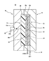
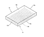
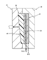
図1を参照して、この発明が適用された導光板用金型構造10は、図2に示すような導光板12を製造するためのものである。
【0010】
導光板12は、アクリル樹脂等のような透光性材料からなり、互いに対向する側端面には入光面12aが形成され、表面(図2における上面)には出光面12bが形成される。また、裏面(図2における下面)には、非出光面12cが形成され、この非出光面12cには複数のドット14aからなる光学パターン14が形成される。
【0011】
光学パターン14を構成するドット14aの分布密度および大きさは、出光面12bの全面において光量が均一となるように設定され、この実施例では、非出光面12cの中央部ほど高密度で大径とされ、端部に向かうにつれて低密度で小径とされる。なお、光学パターン14の各ドット14aは、突起または穴のいずれであってもよいし、ドット14aに代えて、図示しない突条または条溝が形成されてもよい。
【0012】
導光板用金型構造10(図1)は、第1金型16,第2金型18,固定装置20およびレプリカ板24等を含む。
【0013】
第1金型16は、第2金型18と協働してキャビティ(成形品と同一形状の空間部を意味する。以下、同じ。)26を構成する固定型であり、第1金型16の側面には、湯口16aが形成され、湯口16aからキャビティ26へ向けてランナ16bが形成される。
【0014】
第2金型18は、第1金型16と協働してキャビティ26を構成する可動型であり、第2金型18の内部には、キャビティ26の内面を構成するキャビティ面18aと固定装置20が装着される凹部18bとが形成される。
【0015】
固定装置20は、第2金型18に対してレプリカ板24を固定するための「固定手段」として機能するものであり、吸引パネル28,吸引パイプ30,多孔板32および冷却パイプ34を含む。
【0016】
吸引パネル28は中空の板状部材であり、吸引パネル28の表面には、複数の空気吸引孔が形成され、側端部には、吸引パイプ30の一端が接続される。吸引パイプ30の他端には、図示しない真空ポンプが接続される。したがって、真空ポンプが駆動されると、吸引パネル28の表面に形成された空気吸引孔の全てから空気が吸引されることになる。
【0017】
多孔板32は、キャビティ26内においてレプリカ板24を位置決めするとともに、これを固定するものであり、多数の通気孔を有する多孔質材料によって形成される。多孔板32を構成する多孔質材料としては、金属,合成樹脂またはセラミック等のような強度と耐熱性とを兼ね備えたものが用いられる。多孔板32の表面は、レプリカ板24の変形を防止しつつ、これを安定して保持し得るように平滑に仕上げられ、多孔板32の内部には、冷却パイプ34が配置される。そして、冷却パイプ34には、図示しない給水ポンプによって冷却水が循環される。なお、多孔板32および吸引パネル28は、凹部18bの底部に図示しないボルト等により固定される。
【0018】
第1金型16および第2金型18は、図示しない金型プレートに固定され、図示しない油圧シリンダーにより開閉される。そして、第1金型16の湯口16aには、射出装置22の射出ノズル22aが接続される。なお、射出装置22は、射出成形に広く用いられている一般的なものであり、本発明に特有のものではない。
【0019】
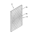
レプリカ板24は、図3に示すように、ニッケル等からなる板状の本体24aを含み、本体24aの表面には、導光板12の光学パターン14(図2)に対応するパターン36が形成される。つまり、光学パターン14を構成する各ドット14aが突起である場合には、パターン36を構成する各ドット36aは穴として形成され、光学パターン14を構成する各ドット14aが穴である場合には、パターン36を構成する各ドット36aは突起として形成される。
【0020】
図1を参照して、導光板用金型構造10を用いて導光板12(図2)を製造する際には、まず、固定装置20によって第2金型18に対してレプリカ板24が固定される。つまり、キャビティ26内にレプリカ板24が配置され、図示しない真空ポンプが駆動されてレプリカ板24の背面が負圧により吸引される。
【0021】
続いて、第1金型16および第2金型18が図示しない油圧シリンダーにより閉鎖されてキャビティ26が構成され、第1金型16の湯口16aに射出装置22の射出ノズル22aが接続される。そして、射出装置22からキャビティ26内へ溶融樹脂が射出される。キャビティ26内に充填された溶融樹脂が所定温度にまで冷却されると、第1金型16および第2金型18が開かれて導光板12が離型される。
【0022】
そして、第2金型18からレプリカ板24を取り外す際には、図示しない真空ポンプが停止され、レプリカ板24の背面に付与されていた負圧が解除される。
【0023】
この実施例によれば、レプリカ板24を用いて光学パターン14を形成するようにしているので、レプリカ板24を取り替えるだけで、異なる種類の導光板12を簡単に製造できる。また、負圧を用いて第2金型18に対してレプリカ板24を固定するようにしているので、ボルト留めする場合に比べて脱着の手間を大幅に軽減でき、また、脱着の際にレプリカ板24を傷つけるのを防止できる。
【0024】
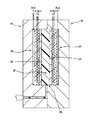
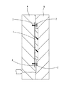
なお、この発明は、図4に示すように、両面に光学パターン14を有する導光板38を製造する場合にも適用可能である。この場合には、第1金型16および第2金型18の両方に固定装置20が装着され、キャビティ26内において2つのレプリカ板24が固定される。
【0025】
また、この発明は、図5に示すように、楔形状の導光板40を製造する場合にも適用可能である。
【0026】
【発明の効果】
この発明によれば、レプリカ板の背面を負圧で吸引することによって金型に対してレプリカ板を固定でき、負圧を解除することによって金型からレプリカ板を取り外すことができる。したがって、レプリカ板を簡単に脱着できるとともに、レプリカ板の損傷を防止できる。
【0027】
また、レプリカ板には、ボルトで固定するための固定部を設ける必要がないので、固定型および可動型の両方にレプリカ板を固定することができ、両面に光学パターンを有する導光板を製造することができる。
【図面の簡単な説明】
【図1】この発明が適用された導光板用金型構造を示す断面図である。
【図2】導光板を示す斜視図である。
【図3】レプリカ板を示す斜視図である。
【図4】他の導光板用金型構造(両面パターン用)を示す断面図である。
【図5】他の導光板用金型構造(楔形用)を示す断面図である。
【図6】従来技術を示す断面図である。
【符号の説明】
10… 導光板用金型構造
12,38,40… 導光板
14… 光学パターン
16… 第1金型
18… 第2金型
20… 固定装置
22… 射出装置
24… レプリカ板
26… キャビティ[0001]
[Industrial applications]
The present invention relates to a light guide plate mold structure for manufacturing a light guide plate having a predetermined optical pattern.
[0002]
[Prior art]
2. Description of the Related Art Generally, a backlight of a liquid crystal display panel uses a surface illumination device for uniformly irradiating light to a display surface, and the surface illumination device guides light from a light source to a display surface. Light guide plate is used. There are various types of light guide plates, and those having an optical pattern including projections, holes, ridges or grooves are well known.
[0003]
Conventionally, when manufacturing a light guide plate having an optical pattern, (a) a nested block in which a pattern corresponding to the optical pattern is machined is placed in a mold, and this is bolted from the back side of the mold. A method of injection molding by fixing, or a method of (b) arranging a replica plate having a pattern in a mold, fixing the replica plate with bolts from the open / close surface side of the mold, and performing injection molding (JP-A-8-6017) Etc.) were adopted.
[0004]
[Problems to be solved by the invention]
However, in the prior art (a), when exchanging the nesting block, it is necessary to remove the mold from the molding machine, so the operation of exchanging the nesting block is troublesome and the exchange operation takes time. There was a problem.
[0005]
On the other hand, in the prior art (b), when replacing the replica plate, there is no need to remove the mold from the molding machine, and by simply replacing the replica plate, a plurality of types of light guide plates can be easily manufactured at low cost. There was a possibility that the replica plate might be damaged when the replica plate was detached. Further, as shown in FIG. 6, since it was necessary to provide the
[0006]
Therefore, a main object of the present invention is to provide a mold structure for a light guide plate that can be detached without damaging the replica plate and that can produce a light guide plate having optical patterns on both surfaces.
[0007]
[Means for Solving the Problems]
According to the present invention, in the light guide
[0008]
According to the present invention, the
[0009]
BEST MODE FOR CARRYING OUT THE INVENTION
Referring to FIG. 1, a light guide
[0010]
The
[0011]
The distribution density and size of the
[0012]
The light guide plate mold structure 10 (FIG. 1) includes a
[0013]
The
[0014]
The
[0015]
The
[0016]
The
[0017]
The
[0018]
The
[0019]
As shown in FIG. 3, the
[0020]
Referring to FIG. 1, when manufacturing light guide plate 12 (FIG. 2) using light guide
[0021]
Subsequently, the
[0022]
Then, when removing the
[0023]
According to this embodiment, since the
[0024]
The present invention is also applicable to a case where a
[0025]
The present invention is also applicable to a case where a wedge-shaped
[0026]
【The invention's effect】
According to the present invention, the replica plate can be fixed to the mold by suctioning the back surface of the replica plate with a negative pressure, and the replica plate can be removed from the mold by releasing the negative pressure. Therefore, the replica plate can be easily attached and detached, and the replica plate can be prevented from being damaged.
[0027]
Further, since it is not necessary to provide a fixing portion for fixing with a bolt on the replica plate, the replica plate can be fixed to both the fixed type and the movable type, and a light guide plate having optical patterns on both surfaces is manufactured. be able to.
[Brief description of the drawings]
FIG. 1 is a cross-sectional view showing a light guide plate mold structure to which the present invention is applied.
FIG. 2 is a perspective view showing a light guide plate.
FIG. 3 is a perspective view showing a replica plate.
FIG. 4 is a cross-sectional view showing another light guide plate mold structure (for a double-sided pattern).
FIG. 5 is a cross-sectional view showing another light guide plate mold structure (for a wedge shape).
FIG. 6 is a cross-sectional view showing a conventional technique.
[Explanation of symbols]
DESCRIPTION OF
Claims (1)
キャビティを構成する金型、
前記光学パターンに対応するパターンを表面に有し、前記キャビティ内に配置されたレプリカ板、および
前記レプリカ板の背面を負圧で吸引することにより前記レプリカ板を前記金型に対して固定する固定手段を備えることを特徴とする、導光板用金型構造。In a light guide plate mold structure for manufacturing a light guide plate having a predetermined optical pattern,
Mold that constitutes the cavity,
A replica plate having a pattern corresponding to the optical pattern on its surface, a replica plate disposed in the cavity, and fixing the replica plate to the mold by suctioning the back surface of the replica plate with a negative pressure. A mold structure for a light guide plate, characterized by comprising means.
Priority Applications (1)
| Application Number | Priority Date | Filing Date | Title |
|---|---|---|---|
| JP2002213921A JP2004050737A (en) | 2002-07-23 | 2002-07-23 | Mold structure for light guide plate |
Applications Claiming Priority (1)
| Application Number | Priority Date | Filing Date | Title |
|---|---|---|---|
| JP2002213921A JP2004050737A (en) | 2002-07-23 | 2002-07-23 | Mold structure for light guide plate |
Publications (1)
| Publication Number | Publication Date |
|---|---|
| JP2004050737A true JP2004050737A (en) | 2004-02-19 |
Family
ID=31936388
Family Applications (1)
| Application Number | Title | Priority Date | Filing Date |
|---|---|---|---|
| JP2002213921A Pending JP2004050737A (en) | 2002-07-23 | 2002-07-23 | Mold structure for light guide plate |
Country Status (1)
| Country | Link |
|---|---|
| JP (1) | JP2004050737A (en) |
-
2002
- 2002-07-23 JP JP2002213921A patent/JP2004050737A/en active Pending
Similar Documents
| Publication | Publication Date | Title |
|---|---|---|
| JP2008514364A5 (en) | ||
| TW200800565A (en) | Injection mold | |
| KR100844548B1 (en) | Mold assembly | |
| WO2019116680A1 (en) | Injection molded article | |
| CN207578825U (en) | A hydraulic ejection type mold base structure for quick and convenient replacement of mold cores | |
| JP2009113339A (en) | Minute shape molding method and apparatus thereof | |
| EP1415958A4 (en) | MOLD, PLATE, SUCTION SUPPORT, METALLIC MOLD, ASSEMBLY / DISASSEMBLY APPARATUS, AND ASSEMBLY / DISASSEMBLY METHOD | |
| JP6886341B2 (en) | Molding mold for resin molding, resin molding equipment, molding mold adjustment method for resin molding, and manufacturing method for resin molded products | |
| JP2004050737A (en) | Mold structure for light guide plate | |
| CN110076961A (en) | A kind of injection mold of instrument light guide plate | |
| CN102529026B (en) | Light guiding board mould core, method for manufacturing light guide plate and light guide plate | |
| CN102854561B (en) | Light guide plate and preparation and application thereof | |
| CN101554761A (en) | Processing method of light guide plate of hot press molding liquid crystal display backlight module illuminating system | |
| JPH09131770A (en) | Method for molding light guide plate and mold used therefor | |
| JP3686186B2 (en) | Mold for resin molding and molding method using the same | |
| CN101683763A (en) | Die insert for manufacturing light guide plate with microstructure and method for manufacturing same | |
| CN100376951C (en) | Light guide plate injection molding mold | |
| TW200618992A (en) | Optical component molding apparatus | |
| CN105946176A (en) | Pluggable core replacement micro injection mold based on quasi static sealing state | |
| JP2007214098A5 (en) | ||
| JP2004130515A (en) | Mold for molding light guide plate and molding method using mold for molding optical product | |
| CN103395150B (en) | Manufacture method for light guide plate | |
| CN103395149B (en) | Manufacture method for light guide plate | |
| JP5543531B2 (en) | Microstructure transfer molding device with release plate | |
| JPWO2012176312A1 (en) | Injection mold apparatus and injection molding machine |
Legal Events
| Date | Code | Title | Description |
|---|---|---|---|
| A621 | Written request for application examination |
Free format text: JAPANESE INTERMEDIATE CODE: A621 Effective date: 20050722 |
|
| A977 | Report on retrieval |
Free format text: JAPANESE INTERMEDIATE CODE: A971007 Effective date: 20070122 |
|
| A131 | Notification of reasons for refusal |
Free format text: JAPANESE INTERMEDIATE CODE: A131 Effective date: 20070206 |
|
| A02 | Decision of refusal |
Free format text: JAPANESE INTERMEDIATE CODE: A02 Effective date: 20070612 |