JP2004040713A - Electrical apparatus having control part - Google Patents

Electrical apparatus having control part Download PDF

Info

Publication number
JP2004040713A
JP2004040713A JP2002198647A JP2002198647A JP2004040713A JP 2004040713 A JP2004040713 A JP 2004040713A JP 2002198647 A JP2002198647 A JP 2002198647A JP 2002198647 A JP2002198647 A JP 2002198647A JP 2004040713 A JP2004040713 A JP 2004040713A
Authority
JP
Japan
Prior art keywords
operation unit
unit
signal
electric device
control unit
Prior art date
Legal status (The legal status is an assumption and is not a legal conclusion. Google has not performed a legal analysis and makes no representation as to the accuracy of the status listed.)
Withdrawn
Application number
JP2002198647A
Other languages
Japanese (ja)
Inventor
Naohito Onoe
尾上 尚人
Current Assignee (The listed assignees may be inaccurate. Google has not performed a legal analysis and makes no representation or warranty as to the accuracy of the list.)
Sanyo Electric Co Ltd
Original Assignee
Sanyo Electric Co Ltd
Priority date (The priority date is an assumption and is not a legal conclusion. Google has not performed a legal analysis and makes no representation as to the accuracy of the date listed.)
Filing date
Publication date
Application filed by Sanyo Electric Co Ltd filed Critical Sanyo Electric Co Ltd
Priority to JP2002198647A priority Critical patent/JP2004040713A/en
Publication of JP2004040713A publication Critical patent/JP2004040713A/en
Withdrawn legal-status Critical Current

Links

Images

Landscapes

  • Control Of Washing Machine And Dryer (AREA)
  • Cookers (AREA)
  • General Electrical Machinery Utilizing Piezoelectricity, Electrostriction Or Magnetostriction (AREA)
  • Transmitters (AREA)
  • Cleaning And Drying Hair (AREA)
  • Washing And Drying Of Tableware (AREA)
  • Induction Heating Cooking Devices (AREA)
  • Electric Ovens (AREA)
  • Electronic Switches (AREA)
  • Selective Calling Equipment (AREA)

Abstract

<P>PROBLEM TO BE SOLVED: To provide a full-automatic washing machine, wherein control part can be arranged on a free position of an electrical apparatus, without being affected by a position of an operation part. <P>SOLUTION: The full-automatic washing machine is provided with the operation part 3 for inputting information, a washing motor 4, and the control part 5 for driving and controlling the washing motor 4 on the basis of input information, which is set and inputted by the operation part 3. The operation part 3 has a wireless state to the control part 5 and has a constitution, wherein supply of power is not received from the outside and a battery function is not installed. The control part 5 drives and controls the washing motor 4, by receiving the input information based on setting input operation in the operation part 3, from the operation part 3. More specifically, the operation part 3 involves a piezoelectric signal generating device 6. When pressing setting input operation is performed by the operation part 3, the piezoelectric signal generating device 6 performs piezoelectric conversion of a signal of the input information, corresponding to the operation and transmits the signal by wireless. <P>COPYRIGHT: (C)2004,JPO

Description

【0001】
【発明の属する技術分野】
本発明は、洗濯機、食器洗い機、電子レンジ、電磁調理器、自動洗髪機等の、操作部を有する電気装置に関する。
【0002】
【従来の技術】
洗濯機等の電気装置においては、操作部で設定入力された情報が制御部へ伝送され、制御部はこの情報に基づいて洗濯モータ等の負荷部を駆動制御する。この場合、操作部は洗濯機の上面前方の操作しやすい場所に設けられており、制御部は操作部に近接した操作部裏面に配置されて配線を介して操作部と接続されている。即ち、制御部は配線の関係上、操作部近辺に設けられている。
【0003】
【発明が解決しようとする課題】
従って、制御部は操作部近辺に配置しなければならないという制約があり、設計自由度が悪い。また、操作部近辺が比較的水分に晒されやすい場所であると、防水対策に注意を払わねばならいないという問題がある。
【0004】
本発明は、かかる背景のもとでなされたもので、設計自由度があり、或いは水分に対する対策の取りやすい、操作部を有する電気装置を提供することを目的とする。
【0005】
【課題を解決するための手段および発明の効果】
上記目的を達成するための本発明は、情報を入力するための操作部と、負荷部と、前記操作部にて設定入力された入力情報に基づいて前記負荷部を駆動制御するための制御部とを備えた操作部を有する電気装置において、前記操作部は前記制御部に対してワイヤレス状態とするとともに外部から電源供給を受けず且つ電池機能を有しない構成とし、前記制御部は前記操作部での設定入力操作に基づいた入力情報を前記操作部から受信して前記負荷部を駆動制御することを特徴とする。
【0006】
ここに、前記操作部は圧電信号発生装置を内蔵し、この圧電信号発生装置は、前記操作部での押圧設定入力操作時、当該操作に対応した入力情報の信号を圧電変換して前記制御部に対してワイヤレス発信する。
【0007】
または、前記操作部は共振回路装置を内蔵し、この共振回路装置は、前記操作部での設定入力操作時、当該操作に対応した入力情報の信号であって前記制御部から発信された信号に共振した信号を、前記制御部に対して送信する。
【0008】
前記負荷部は、洗濯機のモータ、食器洗い機のポンプモータ、電子レンジのマグネトロン、電磁調理器の加熱コイル、自動洗髪機のポンプモータ等であり、電気装置は水分を扱うものである。
【0009】
本発明の構成によれば、操作部は制御部に対してワイヤレス状態であり、制御部は操作部の位置に影響を受けることなく、電気装置の自由な位置に配置することができる。例えば、水分に晒され難い場所に自由に配置できる。
【0010】
また、操作部は制御部に対してワイヤレス状態であるため制御部から電源を受けることができない。ここで、操作部内に電池を内蔵することが考えられるが、電池の消耗時にその都度電池交換を行わねばならず面倒である。
【0011】
而して、本発明の構成においては、操作部は、電池が内蔵されていない構成にて、入力情報を制御部へ伝えることができ、電池交換の面倒さを解消することができる。
【0012】
【発明の実施の形態】
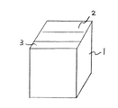
以下に、図面を参照して、本発明の実施形態について具体的に説明する。図1は、本発明の一実施形態に係る全自動洗濯機の外観構成を示す斜視図である。全自動洗濯機は、本体1内に洗濯槽(図示しない)を内蔵しており、この洗濯槽に対して本体1の上面には開閉蓋2が設けられている。そして、本体1の上面前方の操作しやすい場所には、運転情報を入力するための操作部3が設けられている。
【0013】
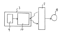
図2は、全自動洗濯機の回路を示す。前記操作部3と、負荷部である洗濯モータ4と、操作部3にて設定入力された入力情報に基づいて洗濯モータ4駆動制御する制御部5とが設けられている。
【0014】
操作部3は制御部5に対してワイヤレス状態であるとともに外部から電源供給を受けず且つ電池機能を有しない構成であり、制御部5は操作部3での設定入力操作に基づいた入力運転情報を操作部3から受信して洗濯モータ4を駆動制御する。
【0015】
具体的には、操作部3は圧電信号発生装置6を内蔵している。この圧電信号発生装置6は、圧電素子7及びこの圧電素子7が発生する電気を受けて作動する周波数発信器8を含み、キーボード9でのキー押圧設定入力操作時、当該キー押圧操作に対応した入力情報の信号を圧電変換して制御部5に対してワイヤレス電波発信する。
【0016】
あるいは、本発明の他の実施形態に係る全自動洗濯機の回路を示す図3のように、操作部3は共振回路装置10を内蔵している。この共振回路装置10は、操作部3での設定入力操作時、共振回路が形成され、当該キー操作に対応した入力情報の信号であって制御部5から発信された電波信号に共振した電波信号を、制御部5へ返す。
【0017】
尚、上記実施例では、本発明の電気装置として全自動洗濯機を例示したが、食器洗い機、電子レンジ、電磁調理器、自動洗髪機等の電気装置(水分を扱う)であっても良い。この場合、食器洗い機にあってはポンプモータ、電子レンジにあってはマグネトロン、電磁調理器にあっては加熱コイル、自動洗髪機にあってはポンプモータが各々負荷部となる。
【0018】
本発明は、以上の実施形態の内容に限定されるものではなく、請求項記載の範囲内において種々の変更が可能である。
【図面の簡単な説明】
【図1】本発明の一実施形態に係る全自動洗濯機の外観斜視図である。
【図2】この全自動洗濯機の回路図である。
【図3】本発明の他の実施形態に係る全自動洗濯機の回路図である。
【符号の説明】
1  洗濯機本体
2  開閉蓋
3  操作部
4  洗濯モータ
5  制御部
6  圧電信号発生装置
7  圧電素子
8  周波数発信器
9  キーボード
10  共振回路装置
[0001]
TECHNICAL FIELD OF THE INVENTION
The present invention relates to an electric device having an operation unit, such as a washing machine, a dishwasher, a microwave oven, an electromagnetic cooker, and an automatic hair washer.
[0002]
[Prior art]
In an electric device such as a washing machine, information set and input by an operation unit is transmitted to a control unit, and the control unit drives and controls a load unit such as a washing motor based on the information. In this case, the operation unit is provided in an easy-to-operate location in front of the upper surface of the washing machine, and the control unit is disposed on the back surface of the operation unit close to the operation unit and connected to the operation unit via wiring. That is, the control unit is provided near the operation unit due to wiring.
[0003]
[Problems to be solved by the invention]
Therefore, there is a restriction that the control unit must be arranged near the operation unit, and the degree of freedom in design is low. In addition, if the vicinity of the operation unit is relatively easily exposed to moisture, there is a problem that attention must be paid to waterproofing measures.
[0004]
The present invention has been made in view of such a background, and an object of the present invention is to provide an electric device having an operation unit that has a degree of freedom in design or that can easily take measures against moisture.
[0005]
Means for Solving the Problems and Effects of the Invention
In order to achieve the above object, the present invention provides an operation unit for inputting information, a load unit, and a control unit for driving and controlling the load unit based on input information set and input by the operation unit. An electrical device having an operating unit having: a configuration in which the operating unit is in a wireless state with respect to the control unit, does not receive power supply from outside, and does not have a battery function; and the control unit includes the operating unit. Receiving the input information based on the setting input operation from the operation unit and controlling the driving of the load unit.
[0006]
Here, the operation unit has a built-in piezoelectric signal generation device, and the piezoelectric signal generation device performs a piezoelectric conversion of a signal of input information corresponding to the operation when the pressure setting input operation is performed on the operation unit, and the control unit includes the control unit. Make a wireless call to.
[0007]
Alternatively, the operation unit has a built-in resonance circuit device, and the resonance circuit device receives a signal of input information corresponding to the operation and a signal transmitted from the control unit when a setting input operation is performed on the operation unit. The resonated signal is transmitted to the control unit.
[0008]
The load unit is a motor of a washing machine, a pump motor of a dishwasher, a magnetron of a microwave oven, a heating coil of an electromagnetic cooker, a pump motor of an automatic hair washer, and the like, and the electric device handles moisture.
[0009]
According to the configuration of the present invention, the operation unit is in a wireless state with respect to the control unit, and the control unit can be arranged at a free position of the electric device without being affected by the position of the operation unit. For example, it can be freely arranged in a place that is hardly exposed to moisture.
[0010]
Further, since the operation unit is in a wireless state with respect to the control unit, it cannot receive power from the control unit. Here, it is conceivable that a battery is built in the operation unit, but the battery must be replaced each time the battery is exhausted, which is troublesome.
[0011]
Thus, in the configuration of the present invention, the operation unit can transmit the input information to the control unit in a configuration in which the battery is not built in, and can eliminate the trouble of replacing the battery.
[0012]
BEST MODE FOR CARRYING OUT THE INVENTION
Hereinafter, embodiments of the present invention will be specifically described with reference to the drawings. FIG. 1 is a perspective view showing an external configuration of a fully automatic washing machine according to one embodiment of the present invention. The fully automatic washing machine has a built-in washing tub (not shown) in a main body 1, and an opening / closing lid 2 is provided on the upper surface of the main body 1 for the washing tub. An operation unit 3 for inputting driving information is provided at an easy-to-operate location in front of the upper surface of the main body 1.
[0013]
FIG. 2 shows a circuit of the fully automatic washing machine. The operation unit 3, a washing motor 4 as a load unit, and a control unit 5 that controls the driving of the washing motor 4 based on input information set and input by the operation unit 3 are provided.
[0014]
The operation unit 3 is in a wireless state with respect to the control unit 5, does not receive power supply from outside, and does not have a battery function. The control unit 5 performs input operation information based on a setting input operation on the operation unit 3. Is received from the operation unit 3 to control the driving of the washing motor 4.
[0015]
Specifically, the operation unit 3 has a built-in piezoelectric signal generator 6. The piezoelectric signal generating device 6 includes a piezoelectric element 7 and a frequency transmitter 8 which operates by receiving electricity generated by the piezoelectric element 7, and corresponds to a key pressing operation when a key pressing setting input operation is performed on the keyboard 9. The signal of the input information is piezoelectrically converted and the radio wave is transmitted to the control unit 5.
[0016]
Alternatively, as shown in FIG. 3 showing a circuit of a fully automatic washing machine according to another embodiment of the present invention, the operation unit 3 has a built-in resonance circuit device 10. In the resonance circuit device 10, a resonance circuit is formed when a setting input operation is performed on the operation unit 3, and a radio signal which is a signal of input information corresponding to the key operation and resonates with a radio signal transmitted from the control unit 5. Is returned to the control unit 5.
[0017]
In the above embodiment, a fully automatic washing machine is exemplified as the electric device of the present invention. However, an electric device (which handles moisture) such as a dishwasher, a microwave oven, an electromagnetic cooker, and an automatic hair washer may be used. In this case, a pump motor is used in a dishwasher, a magnetron is used in a microwave oven, a heating coil is used in an electromagnetic cooker, and a pump motor is used in an automatic hair washer.
[0018]
The present invention is not limited to the contents of the above embodiments, and various modifications can be made within the scope of the claims.
[Brief description of the drawings]
FIG. 1 is an external perspective view of a fully automatic washing machine according to an embodiment of the present invention.
FIG. 2 is a circuit diagram of the fully automatic washing machine.
FIG. 3 is a circuit diagram of a fully automatic washing machine according to another embodiment of the present invention.
[Explanation of symbols]
DESCRIPTION OF SYMBOLS 1 Washing machine main body 2 Opening / closing lid 3 Operation part 4 Washing motor 5 Control part 6 Piezoelectric signal generator 7 Piezoelectric element 8 Frequency transmitter 9 Keyboard 10 Resonance circuit device

Claims (4)

情報を入力するための操作部と、負荷部と、前記操作部にて設定入力された入力情報に基づいて前記負荷部を駆動制御するための制御部とを備えた操作部を有する電気装置において、前記操作部は前記制御部に対してワイヤレス状態とするとともに外部から電源供給を受けず且つ電池機能を有しない構成とし、前記制御部は前記操作部での設定入力操作に基づいた入力情報を前記操作部から受信して前記負荷部を駆動制御することを特徴とする操作部を有する電気装置。An electric device including an operation unit for inputting information, a load unit, and an operation unit including a control unit for driving and controlling the load unit based on input information set and input in the operation unit. The operation unit is configured to be in a wireless state with respect to the control unit, not to receive power supply from the outside, and not to have a battery function, and the control unit transmits input information based on a setting input operation on the operation unit. An electric device having an operation unit, wherein the electric device receives the operation unit and controls the driving of the load unit. 前記操作部は圧電信号発生装置を内蔵し、この圧電信号発生装置は、前記操作部での押圧設定入力操作時、当該操作に対応した入力情報の信号を圧電変換して前記制御部に対してワイヤレス発信することを特徴とする請求項1に記載の操作部を有する電気装置。The operation unit has a built-in piezoelectric signal generation device, and the piezoelectric signal generation device performs a piezoelectric conversion of a signal of input information corresponding to the operation when performing a pressing setting input operation on the operation unit, and transmits the signal to the control unit. The electric device having the operation unit according to claim 1, wherein the electric device transmits the signal wirelessly. 前記操作部は共振回路装置を内蔵し、この共振回路装置は、前記操作部での設定入力操作時、当該操作に対応した入力情報の信号であって前記制御部から発信された信号に共振した信号を、前記制御部に対して送信することを特徴とする請求項1に記載の操作部を有する電気装置。The operation unit has a built-in resonance circuit device, and the resonance circuit device resonates with a signal of input information corresponding to the operation and a signal transmitted from the control unit during a setting input operation on the operation unit. The electric device having an operation unit according to claim 1, wherein a signal is transmitted to the control unit. 前記負荷部は、洗濯機のモータ、食器洗い機のポンプモータ、電子レンジのマグネトロン、電磁調理器の加熱コイル、自動洗髪機のポンプモータ等であり、前記電気装置は水分を扱うことを特徴とする請求項1に記載の操作部を有する電気装置。The load unit is a motor of a washing machine, a pump motor of a dishwasher, a magnetron of a microwave oven, a heating coil of an electromagnetic cooker, a pump motor of an automatic hair washer, and the like, wherein the electric device handles moisture. An electric device comprising the operation unit according to claim 1.
JP2002198647A 2002-07-08 2002-07-08 Electrical apparatus having control part Withdrawn JP2004040713A (en)

Priority Applications (1)

Application Number Priority Date Filing Date Title
JP2002198647A JP2004040713A (en) 2002-07-08 2002-07-08 Electrical apparatus having control part

Applications Claiming Priority (1)

Application Number Priority Date Filing Date Title
JP2002198647A JP2004040713A (en) 2002-07-08 2002-07-08 Electrical apparatus having control part

Publications (1)

Publication Number Publication Date
JP2004040713A true JP2004040713A (en) 2004-02-05

Family

ID=31706042

Family Applications (1)

Application Number Title Priority Date Filing Date
JP2002198647A Withdrawn JP2004040713A (en) 2002-07-08 2002-07-08 Electrical apparatus having control part

Country Status (1)

Country Link
JP (1) JP2004040713A (en)

Cited By (5)

* Cited by examiner, † Cited by third party
Publication number Priority date Publication date Assignee Title
JP2014502440A (en) * 2010-11-04 2014-01-30 アルグラ・ホールディング・アーゲー Piezoelectric signal generator
JP2015033046A (en) * 2013-08-05 2015-02-16 京セラドキュメントソリューションズ株式会社 Operation control device, electronic apparatus, and image forming apparatus
US9307888B2 (en) 2011-11-23 2016-04-12 Whirlpool Corporation System for charging a power supply in a closure element of a household appliance
US9572475B2 (en) 2013-04-29 2017-02-21 Whirlpool Corporation Appliance with closure element having an operative device
US10004379B2 (en) 2011-11-23 2018-06-26 Whirlpool Corporation Dishwasher with transforming door

Cited By (8)

* Cited by examiner, † Cited by third party
Publication number Priority date Publication date Assignee Title
JP2014502440A (en) * 2010-11-04 2014-01-30 アルグラ・ホールディング・アーゲー Piezoelectric signal generator
US9307888B2 (en) 2011-11-23 2016-04-12 Whirlpool Corporation System for charging a power supply in a closure element of a household appliance
US9462926B2 (en) 2011-11-23 2016-10-11 Whirlpool Corporation System for establishing communication between a user interface and a controller of a dishwasher
US9687134B2 (en) 2011-11-23 2017-06-27 Whirlpool Corporation Dishwasher with transforming door
US9999337B2 (en) 2011-11-23 2018-06-19 Whirlpool Corporation System for establishing communication between a user interface and a controller of a dishwasher
US10004379B2 (en) 2011-11-23 2018-06-26 Whirlpool Corporation Dishwasher with transforming door
US9572475B2 (en) 2013-04-29 2017-02-21 Whirlpool Corporation Appliance with closure element having an operative device
JP2015033046A (en) * 2013-08-05 2015-02-16 京セラドキュメントソリューションズ株式会社 Operation control device, electronic apparatus, and image forming apparatus

Similar Documents

Publication Publication Date Title
JP5402212B2 (en) Cooking device with high frequency generator
JP5094426B2 (en) Induction heating cooker and control method of induction heating cooker
JP5264942B2 (en) Electronic equipment, induction heating cooker
JP4869209B2 (en) Input / output device, control method of input / output device, induction cooking device, heating cooking device, refrigerator, washing machine, and jar rice cooker
US8606180B2 (en) User interface for controlling a household electrical appliance remotely connected thereto
US8179060B2 (en) Motor controller for controlling an electric motor
WO2010125786A1 (en) Cooking device
JP2009049880A (en) Input / output device and induction heating cooker, heating cooker, refrigerator, washing machine and jar rice cooker
JP6457294B2 (en) Cooker
EP2302474B1 (en) A control system for a domestic appliance
JP2004040713A (en) Electrical apparatus having control part
JP2014000187A (en) Washing machine control system
JP2009268488A (en) Electric rice cooker
CN111752332A (en) Input Devices and Home Appliances
CN201656944U (en) Touch key with vibration function
CN214946716U (en) Valve actuator capable of being remotely controlled
CN103431778B (en) Boiling heating control apparatus and use the electric cooker of this device
JP3567665B2 (en) Electricity and kotatsu
EP3768045A1 (en) Microwave oven
JP4524857B2 (en) High frequency heating device
CN112104092A (en) Management method for wireless charging of neck massager, neck massager and mobile device
CN212349721U (en) Portable double-frequency ultrasonic cleaning machine
JP2005114262A (en) High frequency heating device
KR20250152603A (en) home appliances
JPWO2024084611A5 (en)

Legal Events

Date Code Title Description
A621 Written request for application examination

Free format text: JAPANESE INTERMEDIATE CODE: A621

Effective date: 20050218

RD01 Notification of change of attorney

Free format text: JAPANESE INTERMEDIATE CODE: A7421

Effective date: 20051226

A761 Written withdrawal of application

Free format text: JAPANESE INTERMEDIATE CODE: A761

Effective date: 20060823