JP2004039215A - Low pressure slider having divided low pressure area, head gimbal assembly, and disk drive - Google Patents
Low pressure slider having divided low pressure area, head gimbal assembly, and disk drive Download PDFInfo
- Publication number
- JP2004039215A JP2004039215A JP2003163673A JP2003163673A JP2004039215A JP 2004039215 A JP2004039215 A JP 2004039215A JP 2003163673 A JP2003163673 A JP 2003163673A JP 2003163673 A JP2003163673 A JP 2003163673A JP 2004039215 A JP2004039215 A JP 2004039215A
- Authority
- JP
- Japan
- Prior art keywords
- slider
- region
- micrometers
- depth
- slider body
- Prior art date
- Legal status (The legal status is an assumption and is not a legal conclusion. Google has not performed a legal analysis and makes no representation as to the accuracy of the status listed.)
- Ceased
Links
Images


Classifications
-
- G—PHYSICS
- G11—INFORMATION STORAGE
- G11B—INFORMATION STORAGE BASED ON RELATIVE MOVEMENT BETWEEN RECORD CARRIER AND TRANSDUCER
- G11B5/00—Recording by magnetisation or demagnetisation of a record carrier; Reproducing by magnetic means; Record carriers therefor
- G11B5/48—Disposition or mounting of heads or head supports relative to record carriers ; arrangements of heads, e.g. for scanning the record carrier to increase the relative speed
- G11B5/58—Disposition or mounting of heads or head supports relative to record carriers ; arrangements of heads, e.g. for scanning the record carrier to increase the relative speed with provision for moving the head for the purpose of maintaining alignment of the head relative to the record carrier during transducing operation, e.g. to compensate for surface irregularities of the latter or for track following
- G11B5/60—Fluid-dynamic spacing of heads from record-carriers
- G11B5/6005—Specially adapted for spacing from a rotating disc using a fluid cushion
Abstract
Description
【0001】
【発明の属する技術分野】
本発明は、ディスクドライブの空気ベアリング式スライダー構造に関する。本発明は特に、空気ベアリング式低圧スライダーのための複数のレベル面構造に関する。
【0002】
【従来の技術】
ハードディスクドライブは、磁気的読み取り及び書き込み要素によってアクセスされる一連の回転可能なディスクを実質的に有する、一般的な情報記憶装置である。これらのデータ転送要素(一般にはトランスデューサーとして知られる)は、典型的にはスライダー本体に支持されて固定される。スライダー本体は、読み取り及び書き込み操作が実行できるように、ディスク上に形成された離散データトラックの上に近接する相対位置に保持される。トランスデューサーをディスク表面に関して適切に配置するために、スライダー本体の上に形成された空気ベアリング表面(ABS)が、スライダー及びトランスデューサーをディスクデータトラックの上方に「浮上(flying)」させるために十分な持ち上げ力を提供する空気流を受ける。高速回転する磁気ディスクは、その表面に沿うとともにディスクの接線速度に実質的平行な方向に、空気流又は風を生じさせる。空気流は、スライダー本体のABSと協働して、回転するディスクの上方にスライダーを浮上させる。実質的に、浮遊するスライダーは、この自己作動的空気ベアリングによってディスク表面から物理的に分離される。スライダーのABSは、回転するディスクに面するスライダー表面上に構成され、種々の条件下においてディスク上方に浮上するための能力に大きく影響する。
【0003】
ABSのいくつかの主目的は、スライダー及びそれに伴うトランスデューサーを、回転するディスクの表面にできるだけ接近して浮上させ、浮上条件の変化に関わらずその接近距離を一様かつ一定に維持することである。空気ベアリング式スライダーと回転する磁気ディスクとの間の高さ又は分離ギャップは、一般に浮上高さとして定義される。一般に、取り付けられたトランスデューサー又は読み取り/書き込み要素は、回転するディスクの表面の僅か約数十ナノメートル(数マイクロインチ)上方を浮上する。スライダーの浮上高さは、取り付けられた読み取り/書き込み要素が有する磁気ディスクの読み取り及び記録能力に影響を与える最も重要なパラメーターの1つとして監視される。例えば、浮上高さを低減すること又は比較的小さい浮上高さを有することは、多くの長所を有する。比較的小さい浮上高さによって、トランスデューサーは相異なるデータビットの位置間でより高い分解能を得ることができ、ディスク表面上に密に画定された領域から磁界が生じることができる。また、浮上高さが低いスライダーは、改善された高密度の記録又は記憶容量の磁気ディスクを提供することが知られている。この記録又は記憶容量は、通常はトランスデューサーと磁気媒体との間の距離によって制限される。狭い分離ギャップにより、より短い波長の信号が記録又は読み取り可能となる。同時に、比較的小さいが強力なディスクドライブを有する軽量かつコンパクトなノートブックタイプのコンピューターの人気の上昇に伴い、浮上高さの低い進歩的に小型化されたスライダー本体のニーズが継続的に高まっている。
【0004】
また一定の浮上高さは、特殊なABSの構成によってより確実に達成可能な望ましい長所を提供することが見出されている。浮上高さの変動は、付随するトランスデューサー又は読み取り/書き込み要素の分解能及びデータ転送能力に不都合に影響することが知られている。記録され又は読み取られる信号の振幅は、浮上高さが比較的一定であるときと同じようには変化しない。さらに、浮上高さの変化は、スライダー組体と回転する磁気ディスクとの間の意図的でない接触に至る場合がある。一般的にスライダーは、直接的、擬似的に接触するスライダー及び浮上するスライダーのいずれとしても考えられており、このことは、それらのスライダーは回転するディスクに意図的に接触することを説明している。スライダーのタイプに関わらず、回転する磁気ディスクの表面に対する不必要な接触を防止して、スライダー本体及びディスク双方の摩耗を低減することが望まれる。記録媒体の劣化又は摩耗は記録データの損失につながる場合があり、一方スライダーの摩耗はトランスデューサー又は磁気要素の究極的な破損に至る場合がある。
【0005】
浮上高さを頻繁に惹き起こすものは、読み取り又は書き込み操作中に、回転するディスクにわたるスライダーの連続的高速移動である。例えば、スライダーの径方向位置によって、ディスク線速度はそれぞれ変化する。回転するディスクは外側エッジにおいて高速に見えるが、内側エッジにおいて低速に見える。結果として、空気ベアリング式スライダーは、ディスクに関する相異なる相対的径方向位置において相異なる相対速度で浮上する。典型的には、スライダーは高速であるほど高く浮上するので、スライダーがディスクの外側領域の上方に配置されたときに浮上高さが大きくなる傾向がある。同時に、内側領域においては低速のためにスライダーはより低く浮上する。従って、スライダーの構成は、径方向位置の変化及び相対速度が浮上高さに与える顕著な影響を排除するものでなければならない。
【0006】
スライダーの浮上高さはまた、スキューの変化によっても悪影響を受ける。スキュー角度は、スライダー本体の長手方向軸とディスク回転に対して接線方向の空気流との間に形成される角度として規定され測定される。取り付けられたスライダーが回転するディスクの内側又は外側エッジの近くに配置されたときは、その長手方向軸はしばしば空気流れ方向に関して斜めになる。スライダーの長手方向軸は、スライダー本体の長さに沿う基準中心線として規定されてもよい。典型的にはこれらの角度方向又はスキュー角度は、回転作動アームとして変化し、ジンバル浮上組体がそのピボット点の回りを回転し、それによりスライダーは回転するディスクにわたって正確な通路を移動する。比較的小さい作動アームを有するコンパクトなディスクドライブの需要が増していることを考慮すれば、アーム長さが小さめであるために、大きめのスキュー角度が常に存在する。スキュー値がゼロより大きいときに、スライダーが加圧されてその値が下げられ、浮上高さが望ましくなく低減するということがしばしば見られる。比較的緩やかなスキュー角度範囲であっても、スライダーの浮上能力は悪影響を受ける。結果として、スキューの変化に対するスライダーの感度を最小化するようにABSを構成することが試みられている。
【0007】
もう1つの浮上高さ変動は、スライダー回転として識別可能である。回転角度は、スライダーの長手方向の両側の間の浮上高さの差によって測定され規定される。空気流れ方向に関するスキューにおいてスライダーが浮上するときは常に、ABSとディスクとの間に生じる圧力分布は不均一になる傾向がある。この不均衡により、スライダー本体の一方の側が他の側よりもディスク表面に接近するようなスライダー回転が生じる。しかしスライダーは、浮上条件のいかなる変化にも関わらず、一定のスライダー回転にて配置されることが好ましい。その浮上条件には、回転するディスクの内側トラックと外側トラックとの間の接線速度差、及びディスク表面の上方の連続的横方向移動又はスキュー角度の変化が含まれる。
【0008】
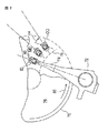
図1に示されるように、一般的な筏型(catamaran)スライダー5として知られるABSの構造は、ディスクに面するスライダー表面の外側エッジに沿って延びる一対の平行なレール2及び4により形成される。様々な表面領域及び形状を備えた、3つ以上の付加的レールを有する他のABS構造も開発されている。典型的には2つのレール2及び4は、前エッジ6から後エッジ8までの長さのスライダー本体の少なくとも一部に沿って延びる。前エッジ6は、回転するディスクが後エッジ8に向けてスライダーを走行する前に通過するスライダーのエッジとして定められる。図示されるように前エッジ6は、定型的には機械加工プロセスに関連した望ましくない大きな許容誤差に関わらず、テーパーを有してもよい。トランスデューサー又は磁気要素7は、図1に示されるように典型的にはスライダーの後エッジ8に沿った場所に取り付けられる。レール2及び4は空気ベアリング表面を形成し、その表面上をスライダーが浮上する。レール2及び4が回転するディスクにより生じる空気流に接したときに、必要とされるスライダーの持ち上げがなされる。ディスクが回転すると、生じた風又は空気流が筏型スライダーレール2及び4の下方に沿ってその間を流れる。空気流がレール2及び4の下方を通過すると、レールとディスクとの間の空気圧力が上昇し、それにより加圧及び持ち上げがなされる。一般に、筏型スライダーによれば十分な持ち上げ高さ又は正の支持力が得られ、それによりスライダーは回転するディスクの上方に適当な高さで浮上する。レール2及び4がない場合は、スライダー本体5の大きな表面領域が過度に大きな空気ベアリング表面を形成する。一般的に、空気ベアリング表面が増加すると、持ち上げ高さも大きくなる。従ってレールがない場合は、スライダーは回転するディスクから離れすぎて浮上するため、低い浮上高さを有することによる先に説明した長所の全ては得られない。
【0009】
図2に示されるように、ヘッドジンバルアセンブリ(HGA)40は、鉛直方向間隔、ピッチ角度及び回転角度のようなスライダーの浮上高さを説明する複数の自由度をスライダーに提供する。図2に示されるように、サスペンション74は、矢印80で示された方向に移動する(エッジ70を有する)ディスク76の上方にHGA40を保持する。図2に示されるディスクドライブの操作中に、アクチュエーター72がHGAを、ディスク76の様々な径(例えば内径ID、中間径MD及び外径OD)に関して弧線75の上方を移動させる。
【0010】
筏型スライダーは、初期は適当な浮上高さの提供に有効であるが、スキュー角度範囲の変化及び他の不都合な浮上条件に対しては特に敏感である。浮上するスライダーが回転するディスクにわたって移動するときのように、スキュー角度が大きくなると、レール下方の空気圧力分布が歪められる。ディスクの内側部分及び外側部分の双方に比較的高速でアクセスすることにより、空気は各レールの下に不均一に導入され、典型的には図1に示されるスライダーの回転を惹起する。その結果スライダーは、不均一な圧力分布の影響を受け、一方向に回転させられて浮上高さがABSのレール間で不均一になる場合がある。従って取り付けられたトランスデューサーは、データ転送操作を効率的又は正確に行うことができない場合がある。変化するスキュー範囲に対するABSレールの感度及び他の不都合な浮上条件にも関わらず、このレール構造は、スライダーの浮上を可能にするために有効な加圧又は持ち上げを行う一般的構造として広く認識されている。
【0011】
浮上するスライダー本体への正の加圧に対抗して低くかつ一定の浮上高さを得るために、スライダー本体をディスクに向けて引っ張る又は引き寄せるために負圧又は常圧より低圧(subambient pressure)を提供するABSを形成することが知られている。例えば、負圧の空気ベアリング(NPAB)又は自己支持式のスライダーが、対抗する負圧支持を提供するものとして知られている。この二重圧力構成においては、ABSは一般に前エッジ、後エッジ、複数のサイドレール、及び複数のサイドレールの間を基本的なH形状方向になるように延びるクロスレールにより形成される。クロスレールは、多くの場合スライダーの後エッジよりも前エッジに接近して配置され、クロスレール及び複数のサイドレールの中間を通る常圧よりも低圧の領域(以下単に低圧領域と称する)を形成する。低圧領域は、ABSのサイドレール部分に沿って生じた正圧に対抗する負圧又は負の支持力を生じさせる。この対抗する負圧及び正圧は、スライダーの安定性及び空気ベアリングの安定性を高め、スライダーを迅速に「離陸」させ、浮上高さ変動を惹起するディスクの速度変化及び径方向移動のような条件変化に対する感度を低減する。ディスクの内側トラックと外側トラックとの間で変化する速度に従って、正圧及び負圧の変化を補正することは、実質的に一定かつ安定した浮上高さを維持するという包括的な目的に寄与する。しかし、低圧構造において生じた対抗力は、実際には浮上高さを変化させるという望ましくない効果をしばしば有する。NPABスライダーは多くの場合、レール下方の不均一な圧力又は空気分布のために、スキュー条件における浮上高さの低減だけでなく顕著な回転を呈する。
【0012】
既に開発されている他の種類のABSレールの変形形態は、横方向等圧線(TPC)として知られている。TPCは、ABSレール上の、空気ベアリング表面領域のエッジに沿う様々な位置に形成可能である。このことは、ある装置において、スキュー角度における浮上高さ変化をいくらか低減することが確認されている。空気流の横方向成分がレールの面を横断する方向に向いているときは、TPCレールの横方向エッジにより提供される等圧線は、等圧線のバランスをとる負圧がレールの他の横方向エッジに沿って等圧線内に生じている間、正圧を受けることができる。その結果、ABSにわたる全体の圧力分布は、空気流の横方向成分が不均一な圧力を形成しがちなスキュー角度の変化範囲に関して、相対的に変化しない状態に維持される。
【0013】
【発明が解決しようとする課題】
空気ベアリング式スライダーについての上述した全てのABS構造及び変形形態は、低くかつ一定の浮上高さを達成するためのものである。効果の程度差は、浮上高さ又はピッチ及び回転角度を全体としては良好に制御しないこれらのABS構造により生じる。例えば、現存する多くのABS構造は、ディスクの外側トラック領域についてスライダー回転角度が著しく大きくなることが確認されている。これらの構造はまた、内側トラック領域から外側トラック領域に移動するときに、スライダーのピッチ角度の増加を制御することが典型的にはできない。従って、空気ベアリング式スライダーのためのABS構造については、ディスクの外側領域及び内側領域における相対速度差、回転するディスクに関するスライダーの相対位置、及び変化するスキュー角度範囲のような絶えず変化する浮上条件に関わらず、一定の浮上高さを効果的に維持して回転角度を制御する必要がある。
【0014】
【課題を解決するための手段】
本発明は、方向が変化する空気流があるときに浮上高さを低くかつ一定にする空気ベアリング表面(ABS)を備えた空気ベアリング式低圧スライダーを提供する。また本発明のスライダー構造により提供される一定の浮上高さは、異なるディスク速度のときに異なる高さ位置に設定することができる。本発明のある実施形態においては、スライダー本体の低圧領域は、第1の領域が予め定めた深さに、第2の領域がそれより深い深さになるように仕切られる。一例として、第1の領域は、スライダーの前部分から複数のレールの間を延び、一方第2の領域はスライダー本体の外側後部の四半部に配置される。
【0015】
【発明の実施の形態】
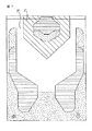
図3は、本発明に係る低圧スライダーのためのABS10の底側の平面図である。以下のABSの特別な特徴を記載するために、Al2O3TiCのような基板材料から形成可能なスライダー本体の全体は図示されないことが理解されよう。図3に図示されるABS10は、有効な空気ベアリング24及び26をそれぞれ備えた一対のレール12及び14を有する。内側レール12及び外側レール14は概ね、ABSの前エッジ16から後エッジ18に向けて延びる。図3に示されるように、ABSレール12及び14は、本発明の一形態に従って、通常の方法により所望の形状に形成される。レール12及び14は、スライダーの前エッジ16において前部分15によって互いに接続される。本発明のこの実施形態においては、前部分15は、スライダーの前エッジから、レール12及び14の間及び外側に延びる。図3において、前部分15は、スライダー部分のその領域を、要求される浮上特性に必要な深さ(例えば0.13〜1.3マイクロメートル(5〜50マイクロインチ))までエッチングすることにより形成される。選択的に、スライダー10の前エッジ16から前部分15に延びる傾斜構造(この技術分野では公知)が使用可能である。
【0016】
図3において、本発明のある実施形態によれば、レール12と14との間の低圧領域が複数の区分に分割される。この実施形態において、低圧領域は、前部分15の後ろで第1領域19と第2領域20とに分割される。この実施形態において、第2領域は、スライダーの後方であってスライダー本体の外側エッジに位置する(移動するディスクに関して)ことから、低圧領域の外側後方四半部と称することができる。第1の低圧領域19は、例えば、その領域を0.51〜2.5マイクロメートル(20〜100マイクロインチ)(例えば1.3マイクロメートル(50マイクロインチ))の深さまでエッチングすることにより形成可能である。好ましくは、低圧領域19の深さは前部分15より深い。この実施形態において、第2低圧領域20は0.51〜5.1マイクロメートル(20〜200マイクロインチ)の深さを有する。好ましくは、第2低圧領域20の深さは第1低圧領域19より深い。従って、例えば第1低圧領域19の深さが1.3マイクロメートル(50マイクロインチ)であるときは、第2低圧領域は3.3マイクロメートル(130マイクロインチ)の深さを有することができる。
【0017】
本発明のこの実施形態において、スライダー10はさらなる特徴を有する。例えば、レール12及び14は、磁気的読み取り/書き込みヘッド22を備えた後部パッド21を有することができる。この実施形態において、後部パッドは2つのレベルを有する。その第1レベル21aは、レール24及び26の深さに等しい深さを有し、第2レベル22aは、0.05〜1.3マイクロメートル(2〜50マイクロインチ)の深さを有する。レール24及び26はまた、後部パッドの第2レベルの深さに等しい深さの第2の構造24a及び26aを有することができる。さらに、レール12及び14より高い高さを有する静電防止パッド25及び27が提供可能である。これらのパッドは、スライダー10において改良された持ち上げを可能にし、スライダー10が移動するディスクに近接したときにレール12及び14が傷つくことを防止する。
【0018】
操作中は、図3に示す仕切られた低圧領域を有するスライダーは、移動するディスクの直径の範囲にわたってより均一な浮上高さを有する。この技術分野では公知のように、回転するディスクの内径と外径との間をスライダーが移動しているときは、空気の流れ方向及び流量が変化する。図3のスライダーにおいて、空気は、内径においては左下方向からある角度にて流れ、外径においては左上方向からある角度にて流れる。低圧領域は内径において、移動するディスクにスライダーが向かうような力を与える。相対的に深い低圧領域20は、低圧領域が均一な深さである場合よりも、スライダーに対するこの力を上昇させる。一方、外径においては、空気流れの方向が異なることから、第2領域がスライダーに対して与えるこの力はより少ない。結果として、スライダーの浮上高さはより均一になる。図4は、図3のスライダーの相対浮上高さ(菱形)及び均一な低圧領域を有するスライダーの相対浮上高さ(四角形)を図示する。図3のスライダーは、内径から外径までの高さ変化が5%未満である。均一な低圧領域を有する場合のスライダーの浮上高さは、移動するディスクの種々の直径に関して最大20%変化し得る。
【0019】
図5〜図8は、本発明の選択的実施形態を図示する。図5において、低圧領域は2つに等分される。低圧領域の内側半分50は、図3の第1領域の深さに相当する深さを有し、外側半分は図3における第2領域の深さに相当する深さを有する。図6の実施形態は、内側半分60が、外側半分61と外側レールとの間の溝60a内を延びる点が異なる。図7において、領域78は図3における第1領域の深さに相当する深さを有し、領域71は図3における第2領域の深さに相当する深さを有する。この実施形態において、領域78は、スライダーの前部分からレールとレールとの間を延び、一方領域71は、後部パッドの側部の前から側部まで延びる。
【0020】
図8の実施形態においては、低圧領域は4つの四半部81〜84に分割される。これら四半部の各々の深さは、内径及び外径の少なくとも一方における条件によって設定可能である。例えば、四半部81及び83の深さは、移動するディスクの内径及び外径のいずれか一方における浮上高さを定めるために設定することができる。浮上高さが定められると、四半部82及び84の深さは、内径及び外径の他方における浮上高さを定めるために設定することができる。内径及び外径の浮上高さは、できるだけ近くなるように設定されることが望ましい。実際の深さの設定は、特定の深さのスライダーを作製し、その特定の深さをインタラクティブなプロセスによって変更することにより可能である。好ましくは、そのプロセスはコンピューターシミュレーション(例えば、後述する式1を用いて)により実行される。
【0021】
全てのスライダーの浮上高さは、正圧(例えばスライダーの空気ベアリングレール上に生じる)と負圧又は低圧(例えばスライダーのレール間の低圧領域)とのバランスに依存する。スライダーの下に生じる圧力の大きさは、以下のように定義可能なベアリング数Aと呼ばれる無次元項によって定められる。
A=6μUL/ph2 式1
ここでμは空気の粘度、Uは空気の線速、Lは代表長さ、pは雰囲気圧力、hは代表高さである。
式1によれば、空気速度の変化は代表高さの変化によって釣り合いを保つことができる。このことは、スライダーの低圧領域の仕切られた領域の数、形状及び深さによって達成される。
【0022】
上述のように構成された、仕切られた低圧領域を有するスライダーの1つの長所は、スライダーが空気速度に鈍感なことである。スライダーが空気速度に鈍感であるときは、スライダーは比較的迅速にディスクから「離陸」してディスク及びスライダーの摩耗を防止することができる。この構成のスライダーの他の長所は、異なる回転速度(例えば5400及び7200rpm)並びに異なる回転高さにおいて作動するドライブに対して同じスライダーが使用できることである。
【0023】
上述の実施形態に関して本発明が説明されたが、好適な実施形態に関するこの説明は限定的な意味に解釈されるものではない。本発明の全ての形態は、本番明細書に記載された特定の描写、構成又は大きさに限定されるものではないことが理解されるべきである。本発明の形態は、種々の空気力学の法則及び変数に依存し、例えば、カリフォルニア州バークレー大学のコンピューター力学研究室(Computer Mechanics Laboratory)にて開発されたようなコンピューターシミュレーションプログラムを用いたコンピューターシミュレーション手法によって規定可能である。既に開示されている装置の形状及び詳細についての様々な変更は、本発明の他の変形例と同様に、本発明を参照すれば当業者には直ちに明らかであろう。従って特許請求の範囲は、記載された実施形態のいかなる修正又は変更も、本発明の真の精神及び範囲に含まれるように意図されたものである。
【図面の簡単な説明】
【図1】テーパーを有する通常の筏型空気ベアリング式スライダー構造を有し、読み取り及び書き込み要素組体を備えた浮上スライダーの斜視図である。
【図2】本発明に従って取り付けられた空気ベアリング式スライダーの平面図である(縮尺は示さず)。
【図3】本発明のある実施形態に従って構成された低圧スライダーの底面図である。
【図4】図3のスライダーの浮上高さを、低圧領域が仕切られていないときの浮上高さと比較したグラフである。
【図5】本発明の他の実施形態に従って構成された低圧スライダーの底面図である。
【図6】本発明の他の実施形態に従って構成された低圧スライダーの底面図である。
【図7】本発明の他の実施形態に従って構成された低圧スライダーの底面図である。
【図8】本発明の他の実施形態に従って構成された低圧スライダーの底面図である。
【符号の説明】
10…スライダー
12、14…レール
16…前エッジ
18…後エッジ
19、20…低圧領域[0001]
TECHNICAL FIELD OF THE INVENTION
The present invention relates to an air-bearing slider structure for a disk drive. The invention particularly relates to a multiple level surface structure for air bearing low pressure sliders.
[0002]
[Prior art]
A hard disk drive is a common information storage device that has substantially a series of rotatable disks accessed by magnetic read and write elements. These data transfer elements (commonly known as transducers) are typically supported and secured to the slider body. The slider body is held in a relative position proximate to discrete data tracks formed on the disk so that read and write operations can be performed. An air bearing surface (ABS) formed on the slider body is sufficient to "fly" the slider and the transducer over the disk data track in order to properly position the transducer with respect to the disk surface. Receiving an airflow that provides a strong lifting force. A rapidly rotating magnetic disk produces an airflow or wind along a surface thereof and in a direction substantially parallel to the tangential velocity of the disk. The airflow cooperates with the ABS of the slider body to levitate the slider above the rotating disk. In effect, the floating slider is physically separated from the disk surface by this self-actuated air bearing. The ABS of the slider is constructed on the slider surface facing the rotating disk and greatly affects its ability to fly above the disk under various conditions.
[0003]
Some of the main objectives of ABS are to levitate the slider and its associated transducer as close as possible to the surface of the rotating disk, and to keep that distance uniform and constant despite changes in flying conditions. is there. The height or separation gap between the air-bearing slider and the rotating magnetic disk is commonly defined as the flying height. Generally, the mounted transducer or read / write element will float only about a few tens of nanometers (several micro inches) above the surface of the rotating disk. The flying height of the slider is monitored as one of the most important parameters affecting the read and write performance of the magnetic disk of the mounted read / write element. For example, reducing the flying height or having a relatively small flying height has many advantages. The relatively small flying height allows the transducer to obtain higher resolution between different data bit locations and magnetic fields can be generated from closely defined areas on the disk surface. Also, sliders with low flying heights are known to provide improved high density recording or storage capacity magnetic disks. This recording or storage capacity is usually limited by the distance between the transducer and the magnetic medium. The narrow separation gap allows shorter wavelength signals to be recorded or read. At the same time, with the increasing popularity of lightweight and compact notebook-type computers with relatively small but powerful disk drives, the need for progressively smaller slider bodies with lower flying heights continues to grow. I have.
[0004]
It has also been found that a constant flying height provides the desired advantage that can be more reliably achieved with a special ABS configuration. Flying height variations are known to adversely affect the resolution and data transfer capabilities of the associated transducer or read / write element. The amplitude of the recorded or read signal does not change as when the flying height is relatively constant. Further, changes in flying height may lead to unintentional contact between the slider assembly and the rotating magnetic disk. In general, sliders are considered as both direct and pseudo contact sliders and floating sliders, which explains that those sliders intentionally contact the rotating disk. I have. Regardless of the type of slider, it is desirable to prevent unnecessary contact with the surface of a rotating magnetic disk and reduce wear on both the slider body and the disk. Deterioration or wear of the recording medium can lead to loss of recorded data, while wear of the slider can lead to ultimate failure of the transducer or magnetic element.
[0005]
Frequently causing flying height is the continuous high speed movement of the slider across a rotating disc during a read or write operation. For example, the disk linear velocity changes depending on the radial position of the slider. The spinning disc appears fast at the outer edge but slower at the inner edge. As a result, the air-bearing slider flies at different relative speeds at different relative radial positions with respect to the disk. Typically, the slider flies higher at higher speeds, so the flying height tends to be higher when the slider is positioned above the outer region of the disc. At the same time, the slider flies lower in the inner area due to the lower speed. Therefore, the configuration of the slider must eliminate the significant effects of radial position changes and relative speed on flying height.
[0006]
The flying height of the slider is also adversely affected by changes in skew. The skew angle is defined and measured as the angle formed between the longitudinal axis of the slider body and the airflow tangential to disk rotation. When the mounted slider is positioned near the inner or outer edge of the rotating disk, its longitudinal axis is often oblique with respect to the direction of air flow. The longitudinal axis of the slider may be defined as a reference centerline along the length of the slider body. Typically, these angular directions or skew angles vary as a rotating actuation arm, causing the gimbal levitation assembly to rotate around its pivot point, thereby causing the slider to move in a precise path across the rotating disk. In view of the increasing demand for compact disk drives with relatively small working arms, there is always a large skew angle due to the small arm length. When the skew value is greater than zero, it is often seen that the slider is pressurized and its value is reduced, resulting in an undesirable decrease in fly height. Even in the relatively gentle skew angle range, the flying ability of the slider is adversely affected. As a result, attempts have been made to configure the ABS to minimize the slider's sensitivity to skew changes.
[0007]
Another flying height variation is identifiable as slider rotation. The rotation angle is measured and defined by the difference in flying height between the two longitudinal sides of the slider. Whenever the slider flies over the skew in the airflow direction, the pressure distribution that occurs between the ABS and the disc tends to be non-uniform. This imbalance causes slider rotation such that one side of the slider body is closer to the disk surface than the other. However, it is preferred that the slider be positioned with a constant slider rotation, regardless of any changes in flying conditions. The flying conditions include the tangential velocity difference between the inner and outer tracks of the rotating disk, and the continuous lateral movement or skew angle change above the disk surface.
[0008]
As shown in FIG. 1, the structure of the ABS, commonly known as a catamaran slider 5, is formed by a pair of
[0009]
As shown in FIG. 2, a head gimbal assembly (HGA) 40 provides the slider with multiple degrees of freedom to account for the slider's flying height, such as vertical spacing, pitch angle and rotation angle. As shown in FIG. 2, suspension 74 holds
[0010]
Raft sliders are initially effective in providing adequate flying height, but are particularly sensitive to changes in skew angle range and other adverse flying conditions. Large skew angles, such as when a flying slider moves across a rotating disk, distort the air pressure distribution below the rails. With relatively fast access to both the inner and outer portions of the disk, air is introduced unevenly beneath each rail, typically causing rotation of the slider shown in FIG. As a result, the slider may be affected by non-uniform pressure distribution and rotated in one direction, causing the flying height to be non-uniform between the ABS rails. Thus, the attached transducer may not be able to perform data transfer operations efficiently or accurately. Despite the sensitivity of the ABS rail to varying skew ranges and other adverse flying conditions, this rail structure is widely recognized as a common structure that provides effective pressurization or lifting to allow for slider lifting. ing.
[0011]
In order to obtain a low and constant flying height against positive pressure on the flying slider body, a negative or sub-ambient pressure is used to pull or pull the slider body towards the disk. It is known to form an ABS to provide. For example, negative pressure air bearings (NPAB) or self-supporting sliders are known to provide opposing negative pressure support. In this dual pressure configuration, the ABS is generally formed by a leading edge, a trailing edge, a plurality of siderails, and a crossrail extending between the plurality of siderails in a basic H-shaped direction. The crossrail is often located closer to the front edge than the rear edge of the slider, forming a region of lower pressure than normal pressure passing between the crossrail and the plurality of siderails (hereinafter simply referred to as a low pressure region). I do. The low pressure region creates a negative pressure or a negative bearing force that opposes the positive pressure generated along the side rail portion of the ABS. This opposing negative and positive pressure enhances the stability of the slider and the stability of the air bearing, causing the slider to "take off" quickly and causing variations in flying height, such as disk speed changes and radial movements. Reduce sensitivity to changing conditions. Compensating for positive and negative pressure changes according to the changing speed between the inner and outer tracks of the disk contributes to the comprehensive purpose of maintaining a substantially constant and stable flying height. . However, the opposing forces created in the low pressure structure often have the undesirable effect of actually changing the flying height. NPAB sliders often exhibit significant rotation as well as reduced fly height in skew conditions due to uneven pressure or air distribution under the rails.
[0012]
Another type of ABS rail variant that has already been developed is known as the transverse isobar (TPC). The TPC can be formed at various locations on the ABS rail along the edge of the air bearing surface area. This has been found to reduce somewhat the flying height change in skew angle in certain devices. When the lateral component of the airflow is oriented in a direction transverse to the plane of the rail, the isobar provided by the lateral edge of the TPC rail is such that a negative pressure balancing the isobar is applied to the other lateral edge of the rail. Along the isobar, a positive pressure can be applied. As a result, the overall pressure distribution across the ABS is maintained relatively unchanged over a range of skew angle changes where the lateral component of the airflow tends to create uneven pressure.
[0013]
[Problems to be solved by the invention]
All the ABS structures and variants described above for air-bearing sliders are for achieving a low and constant flying height. A varying degree of effect is caused by these ABS structures that do not provide good overall control over flying height or pitch and rotation angle. For example, it has been found that many existing ABS structures have significantly increased slider rotation angles for the outer track area of the disk. These structures also typically cannot control the increase in slider pitch angle when moving from the inner track area to the outer track area. Thus, for an ABS structure for an air-bearing slider, the ever-changing flying conditions such as the relative velocity difference in the outer and inner regions of the disk, the relative position of the slider with respect to the rotating disk, and the changing skew angle range. Regardless, it is necessary to control the rotation angle while maintaining a constant flying height effectively.
[0014]
[Means for Solving the Problems]
The present invention provides an air-bearing low-pressure slider with an air-bearing surface (ABS) that provides low and constant flying height in the presence of a changing airflow. Also, the constant flying height provided by the slider structure of the present invention can be set at different height positions at different disc speeds. In one embodiment of the present invention, the low pressure region of the slider body is partitioned such that the first region has a predetermined depth and the second region has a greater depth. As an example, a first region extends between a plurality of rails from a front portion of the slider, while a second region is located in the outer rear quadrant of the slider body.
[0015]
BEST MODE FOR CARRYING OUT THE INVENTION
FIG. 3 is a bottom plan view of the
[0016]
In FIG. 3, according to one embodiment of the present invention, the low pressure area between the
[0017]
In this embodiment of the invention,
[0018]
In operation, the slider with the partitioned low pressure area shown in FIG. 3 has a more uniform flying height over the range of moving disc diameters. As is known in the art, when a slider is moving between the inner and outer diameters of a rotating disk, the direction and flow of air changes. In the slider of FIG. 3, air flows at an angle from the lower left direction at the inner diameter, and flows at an angle from the upper left direction at the outer diameter. The low pressure region provides a force at the inner diameter such that the slider moves toward the moving disk. A relatively deep
[0019]
5 to 8 illustrate alternative embodiments of the present invention. In FIG. 5, the low pressure region is divided into two equal parts. The
[0020]
In the embodiment of FIG. 8, the low pressure area is divided into four quadrants 81-84. The depth of each of these quadrants can be set according to conditions in at least one of the inner diameter and the outer diameter. For example, the depths of the
[0021]
The flying height of all sliders depends on the balance between positive pressure (eg, occurring on the slider's air bearing rails) and negative or low pressure (eg, low pressure areas between slider rails). The magnitude of the pressure generated under the slider is determined by a dimensionless term called the bearing number A, which can be defined as follows.
A = 6 μUL / ph 2 Formula 1
Here, μ is the viscosity of the air, U is the linear velocity of the air, L is the representative length, p is the atmospheric pressure, and h is the representative height.
According to Equation 1, changes in air velocity can be balanced by changes in representative height. This is achieved by the number, shape and depth of the partitioned areas of the low pressure area of the slider.
[0022]
One advantage of a slider having a partitioned low pressure region configured as described above is that the slider is insensitive to air velocity. When the slider is insensitive to air velocity, the slider can "take off" the disk relatively quickly to prevent wear of the disk and the slider. Another advantage of the slider in this configuration is that the same slider can be used for drives operating at different rotational speeds (eg, 5400 and 7200 rpm) and different rotational heights.
[0023]
Although the invention has been described with reference to the above embodiments, this description of the preferred embodiments is not to be construed in a limiting sense. It should be understood that all aspects of the present invention are not limited to the specific depictions, configurations, or dimensions described in the specification. Embodiments of the present invention rely on various aerodynamic laws and variables, and include, for example, computer simulation techniques using computer simulation programs such as those developed at the Computer Mechanics Laboratory at Berkeley University, California. Can be defined by Various modifications in the form and details of the apparatus already disclosed, as well as other variations of the invention, will be readily apparent to those skilled in the art with reference to the invention. It is therefore intended that the following claims be interpreted as including any modification or alteration of the described embodiments as fall within the true spirit and scope of the invention.
[Brief description of the drawings]
FIG. 1 is a perspective view of a flying slider having a conventional raft-type air-bearing slider structure having a taper and having a read / write element assembly.
FIG. 2 is a plan view (not to scale) of an air-bearing slider mounted according to the present invention.
FIG. 3 is a bottom view of a low-pressure slider configured according to an embodiment of the present invention.
FIG. 4 is a graph comparing the flying height of the slider of FIG. 3 with the flying height when a low-pressure area is not partitioned.
FIG. 5 is a bottom view of a low-pressure slider configured according to another embodiment of the present invention.
FIG. 6 is a bottom view of a low-pressure slider configured according to another embodiment of the present invention.
FIG. 7 is a bottom view of a low-pressure slider configured according to another embodiment of the present invention.
FIG. 8 is a bottom view of a low-pressure slider configured according to another embodiment of the present invention.
[Explanation of symbols]
10
Claims (30)
少なくとも第1及び第2レールを有する空気ベアリング面と、
前記スライダー本体の前記前エッジから前記第1及び第2レールの前部まで延びる前部分と、
前記前部分の間かつ前記第1レールと前記第2レールとの間を延び、第1の深さを有する第1の領域及び該第1の深さよりも深い第2の深さを有する第2の領域に少なくとも分割される低圧領域とを有する、低圧スライダー。An air bearing low pressure slider having a slider body, wherein the slider body is defined by a front edge, an inner edge and an outer edge extending longitudinally along the slider body, and a rear edge, wherein the slider body comprises:
An air bearing surface having at least first and second rails;
A front portion extending from the front edge of the slider body to front portions of the first and second rails;
A first region having a first depth and a second region having a second depth greater than the first depth, extending between the front portions and between the first and second rails; And a low-pressure region divided at least into regions.
少なくとも第1及び第2レールを有する空気ベアリング面と、
前記スライダー本体の前記前エッジから前記第1及び第2レールの前部まで延びる前部分と、
前記前部分の間かつ前記第1レールと前記第2レールとの間を延び、第1の深さを有する第1の領域及び該第1の深さよりも深い第2の深さを有する第2の領域に少なくとも分割される低圧領域とを有する、ヘッドジンバルアセンブリ。A head gimbal assembly comprising a slider having a slider body, wherein the slider body is defined by a front edge, an inner edge and an outer edge extending longitudinally along the slider body, and a rear edge, wherein the slider body comprises:
An air bearing surface having at least first and second rails;
A front portion extending from the front edge of the slider body to front portions of the first and second rails;
A first region having a first depth and a second region having a second depth greater than the first depth, extending between the front portions and between the first and second rails; A head gimbal assembly, comprising:
該スライダー本体は前エッジ、該スライダー本体に沿って長手方向に延びる内側エッジ及び外側エッジ、並びに後エッジにより画定され、該スライダー本体が、
少なくとも第1及び第2レールを有する空気ベアリング面と、
前記スライダー本体の前記前エッジから前記第1及び第2レールの前部まで延びる前部分と、
前記前部分の間かつ前記第1レールと前記第2レールとの間を延び、第1の深さを有する第1の領域及び該第1の深さよりも深い第2の深さを有する第2の領域に少なくとも分割される低圧領域とを有する、ディスクドライブ。A disk drive having a rotatable disk and a head gimbal assembly including a slider connected to an actuator and having a slider body,
The slider body is defined by a front edge, inner and outer edges extending longitudinally along the slider body, and a rear edge, the slider body comprising:
An air bearing surface having at least first and second rails;
A front portion extending from the front edge of the slider body to front portions of the first and second rails;
A first region having a first depth and a second region having a second depth greater than the first depth, extending between the front portions and between the first and second rails; And a low-pressure area divided at least into areas.
Applications Claiming Priority (1)
| Application Number | Priority Date | Filing Date | Title |
|---|---|---|---|
| US10/165,786 US6943989B2 (en) | 2002-06-07 | 2002-06-07 | Subambient pressure slider with partitioned subambient area |
Publications (2)
| Publication Number | Publication Date |
|---|---|
| JP2004039215A true JP2004039215A (en) | 2004-02-05 |
| JP2004039215A5 JP2004039215A5 (en) | 2006-07-27 |
Family
ID=29710522
Family Applications (1)
| Application Number | Title | Priority Date | Filing Date |
|---|---|---|---|
| JP2003163673A Ceased JP2004039215A (en) | 2002-06-07 | 2003-06-09 | Low pressure slider having divided low pressure area, head gimbal assembly, and disk drive |
Country Status (3)
| Country | Link |
|---|---|
| US (1) | US6943989B2 (en) |
| JP (1) | JP2004039215A (en) |
| CN (1) | CN1310214C (en) |
Cited By (1)
| Publication number | Priority date | Publication date | Assignee | Title |
|---|---|---|---|---|
| JP2008171536A (en) * | 2006-11-07 | 2008-07-24 | Shinka Jitsugyo Kk | Air bearing design with flatter pitch profile for reducing particle ta's |
Families Citing this family (18)
| Publication number | Priority date | Publication date | Assignee | Title |
|---|---|---|---|---|
| US6879464B2 (en) * | 2002-08-16 | 2005-04-12 | Western Digital (Fremont), Inc. | Air bearing having a cavity patch surface coplanar with a leading edge pad surface |
| JP4643115B2 (en) * | 2002-11-13 | 2011-03-02 | 東芝ストレージデバイス株式会社 | Head slider, recording medium driving device, and head suspension assembly |
| US7190550B2 (en) * | 2003-06-27 | 2007-03-13 | Seagate Technology Llc | Air bearing slider having a bearing profile contoured for pressurization proximate to nodal regions of a slider-disc interface |
| JP2006004539A (en) * | 2004-06-18 | 2006-01-05 | Hitachi Global Storage Technologies Netherlands Bv | Slider and rotary disk-shaped storage device |
| US7352532B2 (en) * | 2005-02-01 | 2008-04-01 | Hitachi Global Storage Technologies Netherlands B.V. | Method and apparatus for utilizing a small pad to increase a head to a disk interface reliability for a load/unload drive |
| US7701564B2 (en) * | 2005-05-18 | 2010-04-20 | Hitachi Global Storage Technologies Netherlands B.V. | System and method for angular measurement |
| JP4041507B2 (en) * | 2005-05-26 | 2008-01-30 | アルプス電気株式会社 | Magnetic head slider |
| US7477486B1 (en) | 2005-12-07 | 2009-01-13 | Western Digital (Fremont), Llc | Air bearing slider with a side pad having a shallow recess depth |
| US8638528B2 (en) * | 2006-02-09 | 2014-01-28 | HGST Netherlands B.V. | Slider air bearing for mobile drives |
| US7719795B2 (en) * | 2006-11-15 | 2010-05-18 | Western Digital (Fremont), Llc | Head having a transducer heater and an air bearing surface with a flow-diversion dam and pressure-relief trough disposed upstream of the transducer |
| US7616405B2 (en) * | 2006-11-15 | 2009-11-10 | Western Digital (Fremont), Llc | Slider with an air bearing surface having a inter-cavity dam with OD and ID dam surfaces of different heights |
| US20080158724A1 (en) * | 2006-12-28 | 2008-07-03 | Dorius Lee K | Slider air bearing for mobile drives |
| US7872833B2 (en) * | 2007-04-17 | 2011-01-18 | Western Digital (Fremont) , LLC | Head with a transducer overcoat having a trailing air flow dam that is shallowly recessed from an air bearing surface |
| US7855854B2 (en) * | 2007-04-17 | 2010-12-21 | Western Digital (Fremont), Llc | Head with an air bearing surface having a shallow recessed trailing air flow dam |
| US7916426B2 (en) * | 2007-11-30 | 2011-03-29 | Western Digital (Fremont), Llc | Head with an air bearing surface having left and right leading pressurizing steps, each with short and long regions |
| US9165579B1 (en) | 2014-09-26 | 2015-10-20 | Western Digital (Fremont), Llc | Air bearing area configuration for reducing flying height hump across a stroke |
| US10984828B1 (en) * | 2020-06-26 | 2021-04-20 | Western Digital Technologies, Inc. | Sliders with low aspect ratio |
| US11776571B1 (en) * | 2022-04-27 | 2023-10-03 | Western Digital Technologies, Inc. | Segmented front bar for particle robustness |
Family Cites Families (10)
| Publication number | Priority date | Publication date | Assignee | Title |
|---|---|---|---|---|
| US5343343A (en) * | 1990-05-25 | 1994-08-30 | Seagate Technology, Inc. | Air bearing slider with relieved rail ends |
| JP2884774B2 (en) * | 1990-12-01 | 1999-04-19 | 株式会社日立製作所 | Information storage device and its manufacturing method |
| US5438467A (en) * | 1992-10-28 | 1995-08-01 | International Business Machines Corporation | Negative pressure air bearing design |
| US5353180A (en) * | 1993-03-01 | 1994-10-04 | Read-Rite Corporation | Air bearing magnetic slider with wishbone-shaped rails |
| JP2790011B2 (en) * | 1993-08-20 | 1998-08-27 | 日本電気株式会社 | Manufacturing method of floating head slider |
| KR100276578B1 (en) * | 1996-10-28 | 2000-12-15 | 니시무로 타이죠 | Head slider and record reproduction device for usig the head slider |
| US6055128A (en) * | 1997-05-14 | 2000-04-25 | International Business Machines Corporation | Dual etch step pad air bearing design with three etch depths |
| US6459546B1 (en) * | 1998-07-21 | 2002-10-01 | Seagate Technology Llc | Altitude insensitive disc head slider |
| JP2000353370A (en) * | 1999-06-09 | 2000-12-19 | Hitachi Ltd | Magnetic head slider capable of controlling floating amount by pressure control groove formed in negative pressure groove, and magnetic disk device having the same loaded |
| US6594113B2 (en) * | 2000-12-20 | 2003-07-15 | Seagate Technology Llc | Slider with furrows for flushing contaminants and lubricant |
-
2002
- 2002-06-07 US US10/165,786 patent/US6943989B2/en not_active Expired - Lifetime
-
2003
- 2003-06-07 CN CNB03147697XA patent/CN1310214C/en not_active Expired - Fee Related
- 2003-06-09 JP JP2003163673A patent/JP2004039215A/en not_active Ceased
Cited By (1)
| Publication number | Priority date | Publication date | Assignee | Title |
|---|---|---|---|---|
| JP2008171536A (en) * | 2006-11-07 | 2008-07-24 | Shinka Jitsugyo Kk | Air bearing design with flatter pitch profile for reducing particle ta's |
Also Published As
| Publication number | Publication date |
|---|---|
| US6943989B2 (en) | 2005-09-13 |
| CN1310214C (en) | 2007-04-11 |
| US20030227717A1 (en) | 2003-12-11 |
| CN1475989A (en) | 2004-02-18 |
Similar Documents
| Publication | Publication Date | Title |
|---|---|---|
| JP2004039215A (en) | Low pressure slider having divided low pressure area, head gimbal assembly, and disk drive | |
| KR0143968B1 (en) | Roll insensitive air bearing slider | |
| US6483667B1 (en) | Self-loading disc head slider having multiple steps approximating a leading taper | |
| US6700727B1 (en) | Slider and method for actively controlling crown curvature | |
| US6771468B1 (en) | Slider with high pitch-stiffness air bearing design | |
| US8446693B2 (en) | System and method for a subambient pressure air bearing slider utilizing negative pressure grooves | |
| US6490135B1 (en) | Disc drive assembly having side rail-channeled air bearing for ramp load-unload applications | |
| US7245455B2 (en) | Center split feature and pressurization for altitude insensitivity, high pitch torque and high preload sensitivity air bearing slider | |
| US7515384B2 (en) | Method and apparatus for providing a three stepped air bearing having a funnel structure for controlling air flow to improve fly height performance | |
| US6710976B2 (en) | Disk head slider having air bearing pressure relief features | |
| US6680821B2 (en) | Slider air bearing surface having improved fly height profile characteristics | |
| US8164860B1 (en) | Servo write robust and good altitude performance ABS | |
| US20110026164A1 (en) | Air bearing surface of a head slider in a hard disk drive | |
| EP0747890A1 (en) | Center rail slider for proximity recording | |
| US6606222B1 (en) | Convergent channel, trenched disc head slider | |
| US6678119B1 (en) | Disc head slider having rails with enclosed depressions | |
| US20020071216A1 (en) | Disc drive having an air bearing surface with trenched contact protection feature | |
| US6034842A (en) | Subambient pressure slider for constant flying height | |
| US7643251B1 (en) | Slider having fast take-off fluid bearing surface | |
| US20020191340A1 (en) | Disc head slider having an air bearing surface for improved damping | |
| JP2005302262A (en) | Slider for high-density magnetic recording, disk drive, and method for manufacturing the slider | |
| US6574074B2 (en) | Air bearing surface design for inducing roll-bias during load/unload sequence | |
| US7233460B2 (en) | Ultra-low flying height slider design | |
| US6765758B1 (en) | Subambient pressure slider including secondary structures in the subambient area | |
| US20060132978A1 (en) | Slider for high density magnetic recording |
Legal Events
| Date | Code | Title | Description |
|---|---|---|---|
| A521 | Written amendment |
Free format text: JAPANESE INTERMEDIATE CODE: A523 Effective date: 20060608 |
|
| A621 | Written request for application examination |
Free format text: JAPANESE INTERMEDIATE CODE: A621 Effective date: 20060608 |
|
| A977 | Report on retrieval |
Free format text: JAPANESE INTERMEDIATE CODE: A971007 Effective date: 20071003 |
|
| A131 | Notification of reasons for refusal |
Free format text: JAPANESE INTERMEDIATE CODE: A131 Effective date: 20071009 |
|
| A601 | Written request for extension of time |
Free format text: JAPANESE INTERMEDIATE CODE: A601 Effective date: 20080108 |
|
| A602 | Written permission of extension of time |
Free format text: JAPANESE INTERMEDIATE CODE: A602 Effective date: 20080111 |
|
| A521 | Written amendment |
Free format text: JAPANESE INTERMEDIATE CODE: A523 Effective date: 20080409 |
|
| A02 | Decision of refusal |
Free format text: JAPANESE INTERMEDIATE CODE: A02 Effective date: 20080729 |
|
| A521 | Written amendment |
Free format text: JAPANESE INTERMEDIATE CODE: A523 Effective date: 20081125 |
|
| A521 | Written amendment |
Free format text: JAPANESE INTERMEDIATE CODE: A523 Effective date: 20081105 |
|
| A911 | Transfer to examiner for re-examination before appeal (zenchi) |
Free format text: JAPANESE INTERMEDIATE CODE: A911 Effective date: 20081209 |
|
| A912 | Re-examination (zenchi) completed and case transferred to appeal board |
Free format text: JAPANESE INTERMEDIATE CODE: A912 Effective date: 20090206 |
|
| A045 | Written measure of dismissal of application [lapsed due to lack of payment] |
Free format text: JAPANESE INTERMEDIATE CODE: A045 Effective date: 20110830 |