CN1310214C - Low environmental pressure slide block having zoning low environment region - Google Patents
Low environmental pressure slide block having zoning low environment region Download PDFInfo
- Publication number
- CN1310214C CN1310214C CNB03147697XA CN03147697A CN1310214C CN 1310214 C CN1310214 C CN 1310214C CN B03147697X A CNB03147697X A CN B03147697XA CN 03147697 A CN03147697 A CN 03147697A CN 1310214 C CN1310214 C CN 1310214C
- Authority
- CN
- China
- Prior art keywords
- area
- slide block
- depth
- degree
- microinchs
- Prior art date
- Legal status (The legal status is an assumption and is not a legal conclusion. Google has not performed a legal analysis and makes no representation as to the accuracy of the status listed.)
- Expired - Fee Related
Links
Images


Classifications
-
- G—PHYSICS
- G11—INFORMATION STORAGE
- G11B—INFORMATION STORAGE BASED ON RELATIVE MOVEMENT BETWEEN RECORD CARRIER AND TRANSDUCER
- G11B5/00—Recording by magnetisation or demagnetisation of a record carrier; Reproducing by magnetic means; Record carriers therefor
- G11B5/48—Disposition or mounting of heads or head supports relative to record carriers ; arrangements of heads, e.g. for scanning the record carrier to increase the relative speed
- G11B5/58—Disposition or mounting of heads or head supports relative to record carriers ; arrangements of heads, e.g. for scanning the record carrier to increase the relative speed with provision for moving the head for the purpose of maintaining alignment of the head relative to the record carrier during transducing operation, e.g. to compensate for surface irregularities of the latter or for track following
- G11B5/60—Fluid-dynamic spacing of heads from record-carriers
- G11B5/6005—Specially adapted for spacing from a rotating disc using a fluid cushion
Abstract
The present invention relates to a low environmental pressure air bearing slide block for a magnetic disk drive and the accessories thereof. A low environmental pressure region is divided into at least two regions. For example, a first region extending in a track has a depth (for example, between 20 to 100 microinches) relative to the height of the track, and simultaneously, a second region has a larger depth (for example, between 20 to 200 microinches). In an embodiment, the second region is positioned in the external back quadrant of a track which is opposite to the edge of the tail of the slide block and is more adjacent to the external diameter of a moving magnetic disk. The slide block can achieve a more uniform transition height within the diameter range of the moving magnetic disk at different rotary speed and different running height of the magnetic disk by zoning the low environmental pressure region and selecting a proper zoning depth.
Description
Technical field
The present invention relates to a kind of air bearing slider that is used for disc driver.More specifically, the present invention is suitable for a kind of multistage surface structure of low environment pressure air bearing slider.
Background technology
Hard disk drive is usual information storage equipment, consists essentially of a series of rotatable disks with the access of magnetic read-write elements.These data transfer element are commonly called sensor, generally by one be positioned at disk on the be closely related slide body of position of the discrete data track that forms carry and embed wherein, to realize the data write operation.For sensor being put into correct position, there is an air-flow to be used for that " flight " on the data in magnetic disk track provides enough lifting forces for slide block and sensor at the air bearing surface that forms on the slide body (ABS) with respect to magnetic disk surface.The high speed rotating of disk produces one air-flow or wind along magnetic disk surface, and its direction is parallel with the tangential velocity of disk substantially.The ABS acting in conjunction of this strand air-flow and slide body makes slide block to leap on the disk of rotation.The slide block that suspends separates with the surface of disk effectively by this self-powered air bearing.The ABS of slide block is formed on the shoe surface facing to spinning disk usually, and influences the ability that the different condition sliding block leaps on disk to a great extent.
Some fundamental purposes of ABS design are to make that distance was near as much as possible when slide block and subsidiary thereon sensor leapt on the spinning disk surface, and keep this constant closely need not consider the condition that leaps that changes equably.Height between air bearing slider and spinning disk or Separation are usually by leaping highly decision.Usually, sensor after the assembling or read/write element only the distance magnetic disk surface at the most a few percent inch above leap.The read/write element after highly being regarded as assembling of leaping of slide block influences disk and reads and note down one of most important evaluating of ability.For example, reduce or have less relatively leaping that many advantages are highly arranged.Less leaping highly can make sensor to reaching bigger resolution between zone, different pieces of information position between the zone of closely defining from magnetic disk surface and magnetic area.Know that one is hanged down apart from the slide block that leaps and can provide improved high density recording or storage capacity for disk, this improvement is limited by the distance between sensor and the magnetic medium usually.Narrow Separation result allows the shorter signal of wavelength to be recorded or to read.Simultaneously, however along with the notebook computer of the relatively little strong disc driver of lighter compacter use is further popular, for the demand that the lower littler slide body that leaps height is arranged also in continuous growth.
People also observe constant leaping highly can provide gratifying benefit, and this can design more easily by special ABS and realize.Known that the unsteady meeting that leaps height has a negative impact to the subsidiary sensor or the resolution and the data ability of passing on of read/write element.When the amplitude that leaps the signal that is recorded or reads when constant highly relatively can significantly not change.In addition, leaping variation highly may cause the slide block assembly parts to contact with the undesigned of magnetic rotating circular disk.Slide block is considered to existing direct contact usually, and false contact also has the slide block that leaps to be described as with the disk that rotates and contacts intentionally.Do not consider the type of slide block, thereby people wish to avoid reducing with the unnecessary contact on spinning disk surface the wearing and tearing of slide body and disk usually.The damage of recording medium or wearing and tearing may cause losing of record data, and the wearing and tearing of slide block simultaneously also can cause the basic inefficacy of sensor or magnetic element.
What often cause leaping height change is the continuous high speed motion that slide block is crossed spinning disk when carrying out read-write operation.For example, the different linear speeds of disk depend on the radial position of slide block.Outward flange at spinning disk can be observed higher speed, and the speed of inward flange is lower simultaneously.As a result of, air bearing slider slides with different relative velocities in different radial positions with respect to disk.Because ram speed is high more, leap highly also highly more, when being positioned at the position of top, disk outside, leap the trend that a kind of increase is highly arranged.Simultaneously, cause slide block to leap lowlyer at the disk interior zone than low velocity.Correspondingly, the design of slide block must consider that the variation of radial position and relative velocity is to leaping the conspicuous influence of height.
Slide block leap the negative effect that highly also is subjected to changes in pitch.The pitch angle is rotated into the definite and measurement of the angle that forms between the direction of tangential air-flow by the longitudinal axis and the relative disk of slide body.Slide block after assembling is positioned at the inboard or the outer ledge of spinning disk, and the common relative wind direction of its longitudinal axis tilts.The longitudinal axis of slide block can be confirmed as the reference center line along the slide body length direction.Thereby when the motion arm of a rotation and universal joint levitated element when its pivot rotation move slide block with arcuate track above spinning disk, these angled directions or pitch angle are typically in variation.Consider to the ever-increasing demand of compact disc driver of relatively little motion arm is arranged, because the appearance of shorter brachium more is bigger pitch angle.Can often observe when tilting value for above zero, the slide block pressurized reduces, and is reluctant the reduction that leaps height seen thereby produce people.Even moderate relatively tilt angle ranges all has negative effect to the ability that leaps of slide block.As a result of, the design of ABS is constantly attempted slide block is minimized the sensitivity of tilt variation.
Another leaps floating of height may be confirmed as slider roll.Roll angle is measured by the difference that leaps height between the vertical limit of slide block and is determined.As long as the direction of slide block relative wind tilts to leap, between ABS and disk, will tend to produce a unbalanced pressure distribution.This imbalance makes one side when slide body when magnetic disk surface is nearer than another side, slider roll.Yet a slide block preferably is set to a constant slider roll and does not consider any variation of the condition of leaping, and comprises in the spinning disk difference of tangential velocity between the outside track, and above disk the continuous pitch angle of transverse movement and variation.
As shown in Figure 1, the ABS that becomes known for common catamaran sliders 5 designs and can be formed by a pair of parallel orbit 2 and 4 that extends along the shoe surface outward flange towards disk.Other comprise three or more additional track, the ABS structure that has different surfaces zone and geometric configuration also has been developed.Two tracks 2 and 4 typically move along at least a portion of 8 the slide body length from leading edge 6 to trailing edge.Leading edge 6 is confirmed as the edge of slide block, and spinning disk will pass through this edge in the length by slide block 5 earlier before trailing edge 8 motions.As shown in the figure, leading edge 6 can be taper, although undesirable high tolerance is typically relevant with this machine work.Sensor or magnetic element 7 are typically installed along certain position of the trailing edge 8 of as shown in Figure 1 slide block.Track 2 and 4 forms an air bearing surface, and slide block leaps thereon, and the lifting force that provides necessary that contacts by the air-flow that produces with spinning disk.When disk rotated, the wind of generation or air-flow were below binary track 2 and 4 and at intermediary movements.Cross the below of track 2 and 4 when air communication, the air pressure between track and the disk increases, thereby normal pressure and lifting force are provided.Catamaran sliders produces the lifting force of sufficient amount usually, or positive load force, so that the proper height of slide block above spinning disk leaps.Do not have track 2 and 4, the big surf zone of slide body 5 can produce a too huge air bearing surface zone.Substantially, when the increase of air bearing surface zone, the lifting force that its produces also increases.Do not have track, slide block may will leap too far apart from spinning disk, thus lose foregoing low leap height be beneficial to.
Illustrate as Fig. 2, a head cardan universal joint component 40 is generally slide block provides a plurality of degree of freedom, for example describes the perpendicular separation that slide block leaps height, or pitch angle and roll angle.As shown in Figure 2, suspended portion 74 head cardan universal joint component 40 is supported on motion disk 76 (edge 70 is arranged) the top and move along the direction of arrow 80 expressions.When operation disc driver shown in Figure 2, executive component 72 makes Sagnetic head universal-joint element move (for example, crossing the internal diameter (ID) of arc 75, middle footpath (MD), external diameter (OD)) on the different-diameter above the disk 76.
Although catamaran sliders is effectively in that suitable leaping on the height is provided at first, they are sensitive especially to tilt angle ranges and other the negative conditions that leap that change.When the pitch angle increase, for example the slide block that ought leap moves above spinning disk, and the air pressure below track distributes and may be twisted.By with the inside and outside zone of relative high speed near disk, the uneven air of quantity is introduced into the below of each track, typically causes slide block to roll as described in Figure 1.The result is, the pressure distribution of slide block is inhomogeneous, makes slide block roll in one direction, like this between the ABS track leap highly inconsistent.So the sensor after the assembling may not valid function or is realized its data transfer operation accurately.Do not consider the ABS track to different slant ranges and other negative sensitivity that leap condition, this orbit Design is to leap the universal architecture that effective pressure or lifting force are provided for slide block by common recognition.
For the normal pressure of offsetting slide body forms one and also provides negative or low environment pressure to come to promote or the ABS of traction slide body towards disk low and the constant height that leaps to be provided, to have known.For example, known negative pressure air bearing (NPAB) or can provide the counteracting negative pressure load from the load slide block.In this dual-pressure system, ABS can have the cross track of a leading edge, trailing edge, siding track and the shape of a H basically guiding of extending usually between siding track.Cross track often is positioned from the slide block leading edge position nearer than trailing edge, produces one along cross track extension and the low environment pressure zone between siding track.The normal pressure that partly produces along the ABS siding track that the low environment pressure zone has produced a negative pressure or load cancellation.The counteracting of having known this positive and negative power has increased the stability of slide block and the hardness of air bearing, taking off fast of slide block is provided, and reduced it to the sensitivity that condition changes, for example can produce and to cause disk speed and the radial motion that leaps the variation of highly floating.And the compensation of the corresponding to positive/negative pressure of speed of the variation in the disk between the outside track changes, and helps the whole purposes that leap height that keep fully constant and stable.But the balancing force that produces in the low environment pressure system may often have a negative impact, and in fact causes leaping the variation of height.Because track unbalanced air pressure in below or distribution, a NPAB slide block often shows tangible rolling, also has the reduction that leaps height under tilt condition.
The ABS track correction of the another kind of type of knowing usually that has developed is transverse pressure structure (TPC).TPC can be formed on the diverse location of ABS track along their edge in air bearing surface zone.Observed under the application-specific the pitch angle it reduced some and leapt variation on the height.When the air-flow that passes raceway surface has horizontal composition, the profile that the transverse edge of TPC track provides can be subjected to normal pressure, and a profile balance negative pressure is produced by the profile along other track transverse edge simultaneously.The result is that the whole pressure distribution on ABS can keep constant relatively, thereby comprise that those horizontal compositions at air-flow are tending towards producing the zone that unbalanced pressure has the change tilt angle ranges.
All are above-mentioned to be used for the ABS structure of air bearing slider and to revise and all attempt to reach low and the constant height that leaps.These ABS designs provide effect in various degree, all can not control well and leap height or inclination and roll angle.For example, many existing ABS designs have been observed and have shown the slider roll angle that the extreme in disk external orbital zone increases.When from the motion of the outside track regions of inner orbit, these structures also typically can not be controlled the increase at slider tilt angle.Like this, need provide a kind of ABS structure for air bearing slider, can effectively keep constant height need not consider to continue variation with the control roll angle the condition that leaps that leaps, the difference of the relative velocity of disk perimeter and interior zone for example, slide block is to the relative position of spinning disk, and different tilt angle ranges.
Summary of the invention
The invention provides a kind of low environment pressure air bearing slider that has air bearing surface (ABS), the low and constant height that leaps is provided when having the air-flow of different directions.And slider designs of the present invention can also be to the constant differing heights that highly is provided under the different disk speed that leaps.In one embodiment of the invention, the low environment pressure zone of slide body is a subregion, such first area at predetermined depth and second area on the darker degree of depth.In an example, the first area is from extending between the track and from the preceding step portion of slide block, and second area is positioned at the outer-back quadrant of slide body simultaneously.
The invention discloses a kind of low environment pressure air bearing slider, comprise: one by leading edge, an inward flange and an outward flange, and the slide body that trailing edge is determined along the slide body longitudinal extension, described slide body comprises: an air bearing surface that comprises at least the first and second tracks; A front portion of extending to the front portion of described first and second tracks from the leading edge of slide block; One forwardly and the low environment pressure zone that extends between first and second tracks, wherein said low environment pressure zone is divided at least the first and second zones, described first area has one first degree of depth and described second area that one second degree of depth is arranged, and described first degree of depth of described second depth ratio is dark, extend between described first track and second track from the front portion of slide body described first area, and described second area is positioned at the rear portion of slide block.
The invention also discloses a kind of head cardan universal joint component, this head cardan universal joint component comprises: a slide block, this slide block comprises one by leading edge, an inward flange and an outward flange along the slide body longitudinal extension, and the slide body that trailing edge is determined, described slide body comprises an air bearing surface that comprises at least the first and second tracks; A front portion of extending to the front portion of described first and second tracks from the leading edge of slide block; One forwardly and the low environment pressure zone that extends between first and second tracks, wherein said low environment pressure zone is divided at least the first and second zones, described first area has one first degree of depth and described second area that one second degree of depth is arranged, and described first degree of depth of described second depth ratio is dark, extend between described first track and second track from the front portion of slide body described first area, and described second area is positioned at the rear portion of slide block.
The invention also discloses a kind of disc driver, this disc driver comprises: a rotatable disk; A head cardan universal joint component that is connected to a regulator, described head cardan universal joint component comprises a slide block, described slide block comprises one by leading edge, an inward flange and an outward flange along the slide body longitudinal extension, and the slide body that trailing edge is determined, described slide body comprises an air bearing surface that comprises at least the first and second tracks; A front portion of extending to the front portion of described first and second tracks from the leading edge of slide block; One forwardly and the low environment pressure zone that extends between first and second tracks, wherein said low environment pressure zone is divided at least the first and second zones, described first area has one first degree of depth and described second area that one second degree of depth is arranged, and described first degree of depth of described second depth ratio is dark, extend between described first track and second track from the front portion of slide body described first area, and described second area is positioned at the rear portion of slide block.
Description of drawings
Fig. 1 is the skeleton view of the slide block that is equipped with read-write elements that has the conventional binary air bearing slider structure of taper.
Fig. 2 is the planimetric map according to the air bearing slider after the present invention's (not in scale) assembling.
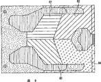
Fig. 3 is the bottom plan view according to the low environment pressure slider of one embodiment of the invention.
Fig. 4 curve map that to be slide block shown in Figure 3 highly do not compared by leaping of the slide block of subregion with the low environment zone.
Fig. 5 is the bottom plan view according to the low environment pressure slider of alternate embodiment of the present invention.
Fig. 6 is the bottom plan view according to the low environment pressure slider of alternate embodiment of the present invention.
Fig. 7 is the bottom plan view according to the low environment pressure slider of alternate embodiment of the present invention.
Fig. 8 is the bottom plan view according to the low environment pressure slider of alternate embodiment of the present invention.
Embodiment
Fig. 3 is the bottom plan view that is used for according to the ABS10 of low environment pressure slider of the present invention.Should be appreciated that in order to be described below the detailed features of ABS, can use for example Al
2O
3The complete slide body that the basic material of TiC forms is not shown.ABS10 shown in Figure 3 comprises pair of tracks 12 and 14, and effective air bearing zone 24 and 26 is arranged respectively.Inner orbit 12 and outside track 14 extend to trailing edge 18 from leading edge 16 beginnings of ABS usually.As shown in Figure 3, ABS track 12 and 14 is made into routine techniques according to one aspect of the present invention and wishes the profile that obtains.Track 12 and 14 leading edges 16 at slide block link together by anterior 15.In these embodiments of the invention, anterior 15 from the leading edge of slide block between track 12 and 14 and outside the extension.In Fig. 3, this front portion 15 is to etch into a degree of depth that leaps feature that is suitable for wishing (for example, between 5 to 20 microinchs) and form by the slide body that will be positioned at this part.Selectively, can adopt 10 leading edges 16 from slide block extend to anterior 15 ramp structure (as
Well known in the prior art).
In Fig. 3, according to one embodiment of the present of invention, the low environment pressure zone between the track 12 and 14 is divided into a plurality of zones.In this example, the low environment pressure zone is divided into a first area 19 and second area 20 after 15 forwardly.In this embodiment, second area can be censured the outer-back quadrant for the low environment pressure zone, because the quadrant that second area comes down to be positioned at the slide block rear portion and is positioned at the zone of slide body external margin (with respect to the disk of motion).The first low environment pressure zone 19 can be formed like this, for example, and by that zone being etched into the degree of depth between 20 to 100 microinchs (as, 50 microinchs).Preferably, the degree of depth of low environment pressure zone 19 will be deeper than anterior 15 the degree of depth.In this embodiment, the degree of depth of the second low environment pressure zone 20 is between 20 to 200 microinchs.Preferably, the degree of depth of 20 to the first low environment pressure zones 19, the second low environment pressure zone is dark.Like this, for example, the degree of depth when zone 19 is 50 microinchs, and the degree of depth of the second low environment pressure zone 20 can be 130 microinchs.
In this embodiment of the present invention, slide block 10 also comprises other features.For example, track 12 and 14 can comprise an afterbody liner 21, and this liner comprises a magnetic read/write head 22.In this example, the afterbody liner has two planes, and a degree of depth equals the first plane 21a of the degree of depth of track 24 and 26, and degree of depth is the second plane 22a between 2 to 50 microinchs.Track 24 and 26 can comprise that also the degree of depth equals second structure 24a and the 26a of the degree of depth on afterbody liner second plane.Further, can also adopt the anti-static friction liner 25,27 that is higher than track 12,14.These liners can provide improved first motion and prevent damage track 12,14 when the disk of slide block 10 distance motions is very near for slide block 10.
When operation, the slide block of the low environment pressure zone that has subregion among Fig. 3 has more unified leaping highly on the diameter range of motion disk.As be known in the art, when slide block moved between the inside diameter of motion disk and outer dia, the direction of air-flow and the amount of air-flow changed.In the slide block of Fig. 3, the air-flow of inside diameter be from the lower left to angle and the air-flow of outer dia be from the upper left side to angle.On inside diameter, the low environment pressure zone provides a power to force the direction of slide block towards the motion disk.Compare with the low environment pressure zone that the unified degree of depth is arranged, darker low environment pressure zone 20 has increased this attractive force to slide block relatively.On the other hand, externally on the diameter because the different directions of air-flow, the second environment pressure zone provide for slide block this attractive force aspect the very little effect of performance.The result provides the more level and smooth height that leaps for slide block.According to Fig. 4, a curve map shows the relative height (representing with square) that leaps that leaps height (representing with rhombus) and the slide block that unified low environment pressure zone is arranged relatively of slide block among Fig. 3.Diameter is to outer dia internally, and the slide block among Fig. 3 is less than 5% in the variation that leaps on the height.The slide block that unified low environment pressure zone is arranged, its variation that leaps height for the different-diameter of motion disk can be up to 20%.
Fig. 5 to 8 shows alternate embodiment of the present invention.In Fig. 5, halved in the low environment pressure zone.The degree of depth of the inside part 50 of low environment pressure zone equals the degree of depth of the first area of Fig. 3, and the degree of depth of Outboard Sections equals the degree of depth of the second area among Fig. 3.In Fig. 6, the dividing mode of low environment pressure zone slide block most of and among Fig. 5 is identical.In this case, the degree of depth of the inside part 60 of low environment pressure zone equals the degree of depth of the first area of Fig. 3, and the degree of depth of Outboard Sections 61 equals the degree of depth of the second area among Fig. 3.The difference of embodiment is among Fig. 6, and inside part 60 extends along the passage 60a between Outboard Sections 61 and the external orbital.In Fig. 7, the degree of depth in zone 78 equals the degree of depth of the first area of Fig. 3, and the degree of depth in zone 71 equals the degree of depth of the second area among Fig. 3.In this embodiment, extend along between the track from the front portion of slide block in zone 78, extends in the place ahead of afterbody liner and towards the edge of afterbody liner with time domain 71.
In the embodiment of Fig. 8, the low environment pressure zone is divided into four quadrant 81-84.The responsible condition that is present in inside and/or outer dia of the degree of depth of each quadrant is determined.As an example, thus the degree of depth of quadrant 81 and 83 can determine to determine to leap height with one of the inside of motion disk or outer dia.Be determined in case leap highly, thereby the degree of depth of quadrant 82 and 84 can be determined extremely to determine to leap height (just, one of outside and inside diameter) with other.What wish is highly to be provided with leaping of inside and outside diameter approaching as far as possible.The accurate setting of the degree of depth can obtain by making slide block with certain depth and changing depth value with repetitive process.Preferably, this process is finished (for example, using the equation 1 that describes below) with computer simulation.
The leaping of any slide block highly all depends on the balance of normal pressure (for example, producing) and negative or low environment pressure (for example, the low environment pressure zone between track) on the air bearing track of slide block.The size of the pressure that produces below slide block depends on the non-diameter condition that is called bearing numerical value A, can be defined as:
Wherein: μ=air viscosity,
The linear speed of U=air,
The L=characteristic length,
The p=environmental pressure,
The h=feature height.
Correspondingly, from equation 1, the variation of gas velocity can come balance by changing feature height.This can reach by quantity, shape and the degree of depth of low environment pressure zone partitioned area of control slide block.
One of possible advantage of the slider designs that has subregion low environment pressure zone as indicated above is that slide block is insensitive to air velocity.When slide block was insensitive to air velocity, slide block can be from the disk " takes off " in fast relatively mode and avoids wearing and tearing to disk and slide block.Another possible advantage according to the design's slide block is that same slide block can be used for the driver with different rotation rates (for example, 5400 and 7200RPM) and differing heights running.
When the present invention is referenced above-mentioned application and describes, be not the restriction of having a mind to of description of preferred embodiments.Should be appreciated that the concrete description, structure or the size that depend on multiple aerodynamic principle and variable that all aspects of the present invention all are not limited to illustrate here, and can be for example use as the computer simulator of computing machine mechanical experiment chamber exploitation that is positioned at the University of California of California Berkeley is determined by computer simulator.In form and details to the difference correction of disclosed equipment, also have of the present invention other to change, be clearly on reference to the basis of the disclosed content of the present invention to those of ordinary skills.
Claims (30)
1. low environment pressure air bearing slider comprises:
One by leading edge, an inward flange and an outward flange, and the slide body that trailing edge is determined along the slide body longitudinal extension, and described slide body comprises:
An air bearing surface that comprises at least the first and second tracks;
A front portion of extending to the front portion of described first and second tracks from the leading edge of slide block;
One forwardly and the low environment pressure zone that extends between first and second tracks, wherein said low environment pressure zone is divided at least the first and second zones, described first area has one first degree of depth and described second area that one second degree of depth is arranged, and described first degree of depth of described second depth ratio is dark, extend between described first track and second track from the front portion of slide body described first area, and described second area is positioned at the rear portion of slide block.
2. slide block as claimed in claim 1, wherein said second area are positioned at the outer-back quadrant of described slide body.
3. slide block as claimed in claim 2, the degree of depth of wherein said first area are between 20 to 100 microinchs, and the degree of depth of described second area is between 20 to 200 microinchs.
4. slide block as claimed in claim 1, extend from the front portion of slide body in the inboard half of low environment pressure zone wherein said first area, and second area extends between described first and second tracks from the front portion of slide body in the outside half of low environment pressure zone.
5. slide block as claimed in claim 2, the degree of depth of wherein said first area between 20 to 100 microinchs and the degree of depth of described second area between 20 to 200 microinchs.
6. slide block as claimed in claim 1, wherein said second area in the outside of low environment pressure zone half and the first area extend from the front portion of slide block in the inboard half of slide block and comprise a passage anterior and that between one of second area and described first, second track, extend along slide block.
7. slide block as claimed in claim 6, the degree of depth of wherein said first area between 20 to 100 microinchs and the degree of depth of described second area between 20 to 200 microinchs.
8. slide block as claimed in claim 1 comprises that also one is positioned near the afterbody liner of slide block trailing edge, and wherein said second area is along described afterbody gasket arrangement.
9. slide block as claimed in claim 8, the degree of depth of wherein said first area between 20 to 100 microinchs and the degree of depth of described second area between 20 to 200 microinchs.
10. slide block as claimed in claim 1, wherein said low environment pressure zone is divided into the first, second, third and the 4th zone.
11. a head cardan universal joint component comprises:
A slide block comprises
One by leading edge, an inward flange and an outward flange, and the slide body that trailing edge is determined along the slide body longitudinal extension, and described slide body comprises
An air bearing surface that comprises at least the first and second tracks;
A front portion of extending to the front portion of described first and second tracks from the leading edge of slide block;
One forwardly and the low environment pressure zone that extends between first and second tracks, wherein said low environment pressure zone is divided at least the first and second zones, described first area has one first degree of depth and described second area that one second degree of depth is arranged, and described first degree of depth of described second depth ratio is dark, extend between described first track and second track from the front portion of slide body described first area, and described second area is positioned at the rear portion of slide block.
12. head cardan universal joint component as claimed in claim 11, wherein said second area are positioned at the outer-back quadrant of described slide body.
13. head cardan universal joint component as claimed in claim 12, wherein for the degree of depth of the described first area of slide block between 20 to 100 microinchs, and the degree of depth of described second area is between 20 to 200 microinchs.
14. head cardan universal joint component as claimed in claim 11, wherein extend from the front portion of slide body in the inboard half of low environment pressure zone, and second area extends between described first and second tracks from the front portion of slide body in the outside half of low environment pressure zone for the described first area of slide block.
15. head cardan universal joint component as claimed in claim 12, wherein for the degree of depth of the described first area of slide block between 20 to 100 microinchs, and the degree of depth of described second area is between 20 to 200 microinchs.
16. head cardan universal joint component as claimed in claim 11, wherein for the described second area of slide block in the outside of low environment pressure zone half and the first area extend from the front portion of slide block in the inboard half of slide block and comprise a passage anterior and that between one of second area and described first, second track, extend along slide block.
17. head cardan universal joint component as claimed in claim 16, wherein for the degree of depth of the described first area of slide block between 20 to 100 microinchs, and the degree of depth of described second area is between 20 to 200 microinchs.
18. head cardan universal joint component as claimed in claim 11, wherein said slide block comprise that also one is positioned near the afterbody liner at slider tail edge, wherein said second area is along described afterbody gasket arrangement.
19. head cardan universal joint component as claimed in claim 18, wherein for the degree of depth of the described first area of slide block between 20 to 100 microinchs, and the degree of depth of described second area is between 20 to 200 microinchs.
20. head cardan universal joint component as claimed in claim 11 wherein is divided into the first, second, third and the 4th zone for the described low environment of slide block pressure zone.
21. a disc driver comprises:
A rotatable disk;
A head cardan universal joint component that is connected to a regulator, described head cardan universal joint component comprises a slide block, described slide block comprises
One by leading edge, an inward flange and an outward flange, and the slide body that trailing edge is determined along the slide body longitudinal extension, and described slide body comprises
An air bearing surface that comprises at least the first and second tracks;
A front portion of extending to the front portion of described first and second tracks from the leading edge of slide block;
One forwardly and the low environment pressure zone that extends between first and second tracks, wherein said low environment pressure zone is divided at least the first and second zones, described first area has one first degree of depth and described second area that one second degree of depth is arranged, and described first degree of depth of described second depth ratio is dark, extend between described first track and second track from the front portion of slide body described first area, and described second area is positioned at the rear portion of slide block.
22. disc driver as claimed in claim 21, wherein said second area are positioned at the outer-back quadrant of described slide body.
23. disc driver as claimed in claim 22, wherein for slide block, the degree of depth of described first area is between 20 to 100 microinchs, and the degree of depth of described second area is between 20 to 200 microinchs.
24. disc driver as claimed in claim 21, wherein extend from the front portion of slide body in the inboard half of low environment pressure zone, and second area extends between described first and second tracks from the front portion of slide body in the outside half of low environment pressure zone for the described first area of slide block.
25. disc driver as claimed in claim 22, wherein for the degree of depth of the described first area of slide block between 20 to 100 microinchs and the degree of depth of described second area between 20 to 200 microinchs.
26. disc driver as claimed in claim 21, wherein for the described second area of slide block in the outside of low environment pressure zone half and the first area extend from the front portion of slide block in the inboard half of slide block and comprise a passage anterior and that between one of second area and described first, second track, extend along slide block.
27. disc driver as claimed in claim 26, wherein for the degree of depth of the described first area of slide block between 20 to 100 microinchs and the degree of depth of described second area between 20 to 200 microinchs.
28. disc driver as claimed in claim 21, wherein said slide block comprise that also one is positioned near the afterbody liner at slider tail edge, wherein said second area is along described afterbody gasket arrangement.
29. disc driver as claimed in claim 28, wherein for the degree of depth of the described first area of slide block between 20 to 100 microinchs and the degree of depth of described second area between 20 to 200 microinchs.
30. disc driver as claimed in claim 21 wherein is divided into the first, second, third and the 4th zone for the described low environment of slide block pressure zone.
Applications Claiming Priority (2)
| Application Number | Priority Date | Filing Date | Title |
|---|---|---|---|
| US10/165,786 US6943989B2 (en) | 2002-06-07 | 2002-06-07 | Subambient pressure slider with partitioned subambient area |
| US10/165786 | 2002-06-07 |
Publications (2)
| Publication Number | Publication Date |
|---|---|
| CN1475989A CN1475989A (en) | 2004-02-18 |
| CN1310214C true CN1310214C (en) | 2007-04-11 |
Family
ID=29710522
Family Applications (1)
| Application Number | Title | Priority Date | Filing Date |
|---|---|---|---|
| CNB03147697XA Expired - Fee Related CN1310214C (en) | 2002-06-07 | 2003-06-07 | Low environmental pressure slide block having zoning low environment region |
Country Status (3)
| Country | Link |
|---|---|
| US (1) | US6943989B2 (en) |
| JP (1) | JP2004039215A (en) |
| CN (1) | CN1310214C (en) |
Families Citing this family (19)
| Publication number | Priority date | Publication date | Assignee | Title |
|---|---|---|---|---|
| US6879464B2 (en) * | 2002-08-16 | 2005-04-12 | Western Digital (Fremont), Inc. | Air bearing having a cavity patch surface coplanar with a leading edge pad surface |
| JP4643115B2 (en) * | 2002-11-13 | 2011-03-02 | 東芝ストレージデバイス株式会社 | Head slider, recording medium driving device, and head suspension assembly |
| US7190550B2 (en) * | 2003-06-27 | 2007-03-13 | Seagate Technology Llc | Air bearing slider having a bearing profile contoured for pressurization proximate to nodal regions of a slider-disc interface |
| JP2006004539A (en) * | 2004-06-18 | 2006-01-05 | Hitachi Global Storage Technologies Netherlands Bv | Slider and rotary disk-shaped storage device |
| US7352532B2 (en) * | 2005-02-01 | 2008-04-01 | Hitachi Global Storage Technologies Netherlands B.V. | Method and apparatus for utilizing a small pad to increase a head to a disk interface reliability for a load/unload drive |
| US7701564B2 (en) * | 2005-05-18 | 2010-04-20 | Hitachi Global Storage Technologies Netherlands B.V. | System and method for angular measurement |
| JP4041507B2 (en) * | 2005-05-26 | 2008-01-30 | アルプス電気株式会社 | Magnetic head slider |
| US7477486B1 (en) | 2005-12-07 | 2009-01-13 | Western Digital (Fremont), Llc | Air bearing slider with a side pad having a shallow recess depth |
| US8638528B2 (en) * | 2006-02-09 | 2014-01-28 | HGST Netherlands B.V. | Slider air bearing for mobile drives |
| US7837885B2 (en) * | 2006-11-07 | 2010-11-23 | Sae Magnetics (Hk) Ltd. | Air bearing design with a flatter pitch profile for reducing particle TAs |
| US7616405B2 (en) * | 2006-11-15 | 2009-11-10 | Western Digital (Fremont), Llc | Slider with an air bearing surface having a inter-cavity dam with OD and ID dam surfaces of different heights |
| US7719795B2 (en) * | 2006-11-15 | 2010-05-18 | Western Digital (Fremont), Llc | Head having a transducer heater and an air bearing surface with a flow-diversion dam and pressure-relief trough disposed upstream of the transducer |
| US20080158724A1 (en) * | 2006-12-28 | 2008-07-03 | Dorius Lee K | Slider air bearing for mobile drives |
| US7872833B2 (en) * | 2007-04-17 | 2011-01-18 | Western Digital (Fremont) , LLC | Head with a transducer overcoat having a trailing air flow dam that is shallowly recessed from an air bearing surface |
| US7855854B2 (en) * | 2007-04-17 | 2010-12-21 | Western Digital (Fremont), Llc | Head with an air bearing surface having a shallow recessed trailing air flow dam |
| US7916426B2 (en) * | 2007-11-30 | 2011-03-29 | Western Digital (Fremont), Llc | Head with an air bearing surface having left and right leading pressurizing steps, each with short and long regions |
| US9165579B1 (en) | 2014-09-26 | 2015-10-20 | Western Digital (Fremont), Llc | Air bearing area configuration for reducing flying height hump across a stroke |
| US10984828B1 (en) * | 2020-06-26 | 2021-04-20 | Western Digital Technologies, Inc. | Sliders with low aspect ratio |
| US11776571B1 (en) * | 2022-04-27 | 2023-10-03 | Western Digital Technologies, Inc. | Segmented front bar for particle robustness |
Citations (2)
| Publication number | Priority date | Publication date | Assignee | Title |
|---|---|---|---|---|
| CN1199828A (en) * | 1997-05-14 | 1998-11-25 | 国际商业机器公司 | Dual etch step process for air bearing design with three etch depths |
| JP2000353370A (en) * | 1999-06-09 | 2000-12-19 | Hitachi Ltd | Magnetic head slider capable of controlling floating amount by pressure control groove formed in negative pressure groove, and magnetic disk device having the same loaded |
Family Cites Families (8)
| Publication number | Priority date | Publication date | Assignee | Title |
|---|---|---|---|---|
| US5343343A (en) * | 1990-05-25 | 1994-08-30 | Seagate Technology, Inc. | Air bearing slider with relieved rail ends |
| JP2884774B2 (en) * | 1990-12-01 | 1999-04-19 | 株式会社日立製作所 | Information storage device and its manufacturing method |
| US5438467A (en) * | 1992-10-28 | 1995-08-01 | International Business Machines Corporation | Negative pressure air bearing design |
| US5353180A (en) * | 1993-03-01 | 1994-10-04 | Read-Rite Corporation | Air bearing magnetic slider with wishbone-shaped rails |
| JP2790011B2 (en) * | 1993-08-20 | 1998-08-27 | 日本電気株式会社 | Manufacturing method of floating head slider |
| US6021020A (en) * | 1996-10-28 | 2000-02-01 | Kabushiki Kaisha Toshiba | Head slider and read/write apparatus using same |
| US6459546B1 (en) * | 1998-07-21 | 2002-10-01 | Seagate Technology Llc | Altitude insensitive disc head slider |
| US6594113B2 (en) * | 2000-12-20 | 2003-07-15 | Seagate Technology Llc | Slider with furrows for flushing contaminants and lubricant |
-
2002
- 2002-06-07 US US10/165,786 patent/US6943989B2/en not_active Expired - Lifetime
-
2003
- 2003-06-07 CN CNB03147697XA patent/CN1310214C/en not_active Expired - Fee Related
- 2003-06-09 JP JP2003163673A patent/JP2004039215A/en not_active Ceased
Patent Citations (2)
| Publication number | Priority date | Publication date | Assignee | Title |
|---|---|---|---|---|
| CN1199828A (en) * | 1997-05-14 | 1998-11-25 | 国际商业机器公司 | Dual etch step process for air bearing design with three etch depths |
| JP2000353370A (en) * | 1999-06-09 | 2000-12-19 | Hitachi Ltd | Magnetic head slider capable of controlling floating amount by pressure control groove formed in negative pressure groove, and magnetic disk device having the same loaded |
Also Published As
| Publication number | Publication date |
|---|---|
| US20030227717A1 (en) | 2003-12-11 |
| JP2004039215A (en) | 2004-02-05 |
| US6943989B2 (en) | 2005-09-13 |
| CN1475989A (en) | 2004-02-18 |
Similar Documents
| Publication | Publication Date | Title |
|---|---|---|
| CN1310214C (en) | Low environmental pressure slide block having zoning low environment region | |
| CN1070304C (en) | Slider supporting structure of magnetic disk unit | |
| US6411468B1 (en) | Pseudo-contact negative pressure air bearing slider with dual negative pressure pockets and central transducer | |
| KR100278422B1 (en) | Design of negative pressure step pad type air bearing and its manufacturing method | |
| CN1058802C (en) | Roll insensitive air bearing slider | |
| CA2071453C (en) | Slider air bearing surface with angled rail configuration | |
| US5210666A (en) | Self-loading air bearing slider with a relieved leading edge | |
| US6477012B1 (en) | Flying negative pressure air bearing slider with dual negative pressure pockets and side transducer | |
| CN100538825C (en) | Utilize the system and method for the hypobaric air bearing slider of negative pressure trough | |
| KR910001150B1 (en) | Flanged tranducer supporting arm for a magnetic head/arm assembly | |
| WO2002084650A1 (en) | Air bearing slider | |
| US5870251A (en) | Taperless/crown free/air bearing design | |
| CN1063565C (en) | Disk drive with passive multiple PLY height slider and cooperative disk pattern | |
| KR100208382B1 (en) | Air bearing slider with variable sub-ambient pressure control | |
| US6459546B1 (en) | Altitude insensitive disc head slider | |
| US6421908B1 (en) | Method of making shallow etch air bearing surface features for optimized transducer spacing | |
| US6646831B1 (en) | Air bearing slider having optimized etch depth ratio | |
| CN1076500C (en) | Magnetic head sub-ambient air pressure slider for a disc drive device or the like | |
| US6501621B1 (en) | Air bearing slider having improved take-off velocity | |
| CN101281753B (en) | Slider designed to reduce fly height sigma | |
| CN1163896C (en) | Subambient pressure slider | |
| CN1577594A (en) | Ultra-low flying height slider design | |
| CN1296933C (en) | Disc head slider having profiled convergent channel features | |
| JPH09503607A (en) | Constant flying height slider with reduced roll moment sensitivity | |
| WO1998032127A1 (en) | Taperless/crown free/air bearing design |
Legal Events
| Date | Code | Title | Description |
|---|---|---|---|
| C06 | Publication | ||
| PB01 | Publication | ||
| C10 | Entry into substantive examination | ||
| SE01 | Entry into force of request for substantive examination | ||
| C14 | Grant of patent or utility model | ||
| GR01 | Patent grant | ||
| CF01 | Termination of patent right due to non-payment of annual fee |
Granted publication date: 20070411 Termination date: 20190607 |
|
| CF01 | Termination of patent right due to non-payment of annual fee |