JP2004036384A - Drain pipe joint and its connecting structure - Google Patents
Drain pipe joint and its connecting structure Download PDFInfo
- Publication number
- JP2004036384A JP2004036384A JP2003300197A JP2003300197A JP2004036384A JP 2004036384 A JP2004036384 A JP 2004036384A JP 2003300197 A JP2003300197 A JP 2003300197A JP 2003300197 A JP2003300197 A JP 2003300197A JP 2004036384 A JP2004036384 A JP 2004036384A
- Authority
- JP
- Japan
- Prior art keywords
- pipe
- pipe joint
- concrete slab
- horizontal branch
- downstream
- Prior art date
- Legal status (The legal status is an assumption and is not a legal conclusion. Google has not performed a legal analysis and makes no representation as to the accuracy of the status listed.)
- Pending
Links
Images


Abstract
Description
この発明は、例えばマンション等の集合住宅の排水経路において、上階から下階を貫いて配管された立て管に各階の横枝管を接続するための排水管継手およびその接続構造に関する。 The present invention, for example in drainage path collective housing apartments, etc., about the drainage pipe joint hands and its connection structure for connecting the floor of the lateral branch pipe to the standpipe which is piping through the lower floor from the upper floor.
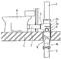
図6は、上記排水管継手を用いた配管施工例を示している。図示するようにこの排水管継手1は、上階と下階を区画するコンクリートスラブ4を貫通する状態に固定(埋め戻し)若しくは支持されている。この排水管継手1は、横枝管7を接続するための横枝管受け口5,6を備えた胴部10と、該胴部10の上部に設けられ、上流側の立て管2を接続するための上部受け口1aと、該胴部10の下部に設けられ、下流側の立て管3を接続するための下部接続部1bを有している。横枝管7を介して大便器8が排水管継手1ひいては立て管3に接続されている。
又、近年この種の排水管継手1には、流入した排水を螺旋状に旋回させるための旋回羽根9が管内方に張り出し状に設けられており、該旋回羽根9に流下する排水を衝突させて旋回流を発生させることにより管中心に常時大気に連通した空気コアを形成し、これにより管内圧力を常時大気圧に保持して排水流下に伴う管内圧力の変動を抑制するいわゆる単管式排水システムが主流となっている。
In recent years, the drainage fitting 1 of this type is provided with a swirling blade 9 for spirally turning the inflowing drainage inwardly in a pipe, so that the drainage flowing down to the swirling blade 9 is caused to collide. A so-called single-pipe type drain that generates a swirling flow to form an air core constantly communicating with the atmosphere at the center of the pipe, thereby keeping the pipe pressure constantly at atmospheric pressure and suppressing fluctuations in the pipe pressure accompanying the drainage flow The system is mainstream.
このように、従来旋回羽根9を備えた排水管継手1をコンクリートスラブ4に直接埋め戻して固定していたため、流下する排水が旋回羽根9に衝突した際の衝撃が振動となってコンクリートスラブ4に伝播し、これが特に下階の住人にとって不快な排水騒音となる問題があった。
又、上記旋回羽根9を有しない排水管継手1であっても、流入する横枝管排水が管内壁に衝突すること等により振動が発生し、これによっても排水騒音を生ずる問題があった。
本発明は、この問題に鑑みなされたもので、排水管継手から振動が発生しても排水騒音を大幅に緩和することができる排水管継手およびその接続構造を提供することを目的とする。
As described above, since the
Further, even in the
The present invention has been made in view of this problem, and has as its object to provide a drainage pipe joint that can significantly reduce drainage noise even when vibration is generated from the drainage pipe joint, and a connection structure thereof.
このため本発明は、特許請求の範囲に記載した構成の排水管継手またはその接続構造とした。
請求項1記載の排水管継手によれば、立て管排水経路に横枝管を接続するための排水管継手がコンクリートスラブに直接固定されるのではなく、該コンクリートスラブに固定した下流側の立て管を介して接続される。しかも、排水管継手の下部接続部と下流側の立て管の受け口との間には当該受け口に装着されているパッキンが介在されるので、排水管継手で発生した振動は該パッキンに吸収され、従ってコンクリートスラブに伝播する振動は大幅に低減される。
このことから、例えば排水管継手の内部に旋回羽根が設けられているため、該旋回羽根に排水が衝突することにより振動が発生してもコンクリートスラブには伝わりにくく、これにより排水騒音を大幅に低減することができる。
なお、上記旋回羽根が設けられていない排水管継手であっても、横枝管から排水が流入することにより発生する振動がコンクリートスラブに伝播しにくので、上記と同様に排水騒音を大幅に低減することができる。
For this reason, the present invention provides a drainage pipe joint having the configuration described in the claims or a connection structure thereof .
According to the drainage pipe joint according to the first aspect, the drainage pipe joint for connecting the horizontal branch pipe to the stack pipe drainage path is not directly fixed to the concrete slab, but is fixed to the concrete slab on the downstream side. Connected via a tube. In addition, since the packing mounted on the receiving port is interposed between the lower connection portion of the drain pipe joint and the receiving port of the downstream standing pipe, vibration generated at the drain pipe joint is absorbed by the packing, Therefore, the vibration propagating to the concrete slab is greatly reduced.
For this reason, for example, since the swirl vanes are provided inside the drainage pipe joint, even if vibration occurs due to the collision of the drainage with the swirl vanes, it is difficult for the vibration to be transmitted to the concrete slab, thereby greatly reducing the drain noise. Can be reduced.
In addition, even in the case of the drain pipe joint not provided with the swirling vanes, since the vibration generated by the inflow of the drain water from the horizontal branch pipe is difficult to propagate to the concrete slab, the drain noise is significantly reduced as described above. Can be reduced.
請求項2記載の排水管継手によれば、直管形状の下部接続部を下流側の立て管の受け口に挿入して、当該排水管継手に下流側の立て管が接続され、かつこの下流側の立て管の受け口がその上端部をコンクリートスラブの上面に面一に揃えた状態で当該コンクリートスラブに固定されていることにより、排水管継手の横枝管受け口をコンクリートスラブの上面に近接させた状態で接続することができるので、床下スペースが低い場合であっても、容易に横枝管の配管をすることができる。
近年、居室の床面に段差のない、いわゆるバリアフリー構造や、水回りの位置を居住者の好みの位置に配置できるフリープラン構造が普及しており、床下の横枝管の配管スペース(コンクリートスラブの上面と床板とのすきま寸法)が不足がちで、排水管継手の横枝管受け口を極力スラブ上面に近づけて配管したいという要求がある。請求項2記載の排水管継手によれば、このようなバリアフリー構造や、フリープラン構造に対する要求にも、容易に応じることができる。
請求項3記載の排水管継手または請求項6記載の接続構造によれば、上記と同様排水騒音のコンクリートスラブへの伝播を低減することができる。
更に、請求項4記載の排水管継手によれば、いわゆる耐火二層管形式の排水管継手についても上記と同様の作用効果を得ることができる。すなわち、塩化ビニール製内管の表面をモルタル製の耐火被覆層で覆った耐火二層管継手の場合であっても、該継手内に排水が流入し、内壁面に衝突すること等により振動が発生しても、該振動がコンクリートスラブに直接伝播しないので、このような振動を原因とする排水騒音を大幅に低減することができる。また、内管の下部接続部(耐火被覆層が剥がされたむき出しの塩化ビニール直管部)を、下流側の立て管の上部受け口に挿入して接続する構成であるので、上記と同様横枝管をコンクリートスラブの上面に接近させて接続することができるようになる。
又、請求項5記載の排水管継手によれば、上記作用効果に加えて、横枝管をコンクリートスラブの上面により接近させて配管することができ、これにより前記と同様床下スペースを小さくして容易にバリアフリー構造に対応できるようになる。
According to the drainage pipe joint according to
In recent years, the so-called barrier-free structure, which has no steps on the floor of a living room, and the free-plan structure, in which the location around the water can be arranged at a resident's preferred position, have become widespread. The clearance between the upper surface of the slab and the floor plate) is apt to be insufficient, and there is a demand that the piping of the horizontal branch pipe of the drainage pipe joint be as close as possible to the upper surface of the slab. According to the drainage pipe joint according to the second aspect, it is possible to easily meet the demand for such a barrier-free structure and a free plan structure.
According to the drainage pipe joint according to
Further, according to the drainage pipe joint according to the fourth aspect, the same operation and effect as described above can be obtained for a so-called fireproof double-layer pipe type drainage pipe joint. That is, even in the case of a fire-resistant double-layer pipe joint in which the surface of a vinyl chloride inner pipe is covered with a mortar fire-resistant coating layer, drainage flows into the joint, and vibration is caused by collision with the inner wall surface. Even if it occurs, the vibration does not directly propagate to the concrete slab, so that drainage noise caused by such vibration can be significantly reduced. In addition, since the lower connection part of the inner pipe (the exposed straight PVC pipe part with the refractory coating layer removed) is inserted into the upper receptacle of the standing pipe on the downstream side and connected, the horizontal branch is similar to the above. The pipe can be connected close to the upper surface of the concrete slab.
Further, according to the drainage pipe joint according to
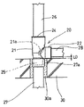
次に、本発明の実施の形態を図1〜図5に基づいて説明する。図1は、第1実施形態に係る排水管継手20の接続構造を示している。この排水管継手20は、胴部21と、該胴部21の周囲に設けた横枝管受け口22と、胴部21の上部に設けた上部受け口24と、胴部の下部に設けた下部接続部25を有している。
横枝管受け口22には、横枝管28を介して例えば前記大便器8(図1では省略)が接続されている。本実施形態の場合、この横枝管受け口22の内周側には略円筒形状のパッキンが介装されており、該パッキンの内周側に横枝管28を挿入するのみで、該横枝管28が受け口22に対して水密に接続されている。このワンタッチ式の接続構造の場合、横枝管受け口22にはボルト接合用のフランジ部等外周側に張り出す部位は設けられていない。
胴部21の内周側には、流下する排水を旋回させるための旋回羽根21aが管内方へ螺旋状に張り出し状に設けられている。上流側の立て管26から流下した立て管排水はこの旋回羽根21aに衝突することにより減速し、減速した後該旋回羽根21aに案内されて旋回流となる。なお、旋回羽根21aに代えて若しくは加えて庇状に張り出すガイドを設けることもできる。
上部受け口24には、図示省略したパッキンを介して上流側の立て管26が挿入されている。
Next, an embodiment of the present invention will be described with reference to FIGS. FIG. 1 shows a connection structure of a
For example, the toilet 8 (omitted in FIG. 1) is connected to the horizontal branch
On the inner peripheral side of the
An upstream standing
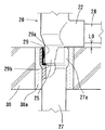
下部接続部25は、図示するように直管形状を有している。この下部接続部25は、下流側の立て管27の上部受け口27aに挿入されている。図2に示すように下部接続部25と、上部受け口27aの内周面との間には、ゴム製のパッキン29が介装されている。このパッキン29は略円筒形状を有し、その内周側には環状の舌状片29aが全周にわたって設けられている。この舌状片29aの内周側に、排水管継手20の下部接続部25が挿入されており、この舌状片29aが下部接続部25に弾性的に密着することにより、該下部接続部25が下流側の立て管27に対して水密に接続される。
しかも、上記舌状片29aは下部接続部25に対して弾性的に押圧されているので、排水管継手20に振動が発生しても、該舌状片29aによりこの振動は吸収される。
又、上記パッキン29の下端部には、内周側に張り出す緩衝片29bが設けられており、この緩衝片29bに下部接続部25の下端が突き当てられている。この緩衝片29bが弾性変形することにより、下部接続部25の熱膨張が吸収される。
本実施形態の場合、上記のように下部接続部25が緩衝片29bに突き当たる状態にまで差し込まれると、図示するように横枝管受け口22がコンクリートスラブ30の上面にほぼ接触する高さに位置し、これにより横枝管28が最も低い位置(最もコンクリートスラブ30の上面に近い目的の位置)に配管されている。
The
In addition, since the
At the lower end of the
In the case of the present embodiment, when the lower connecting
次に、下流側の立て管27は、コンクリートスラブ30に埋め戻されて(埋め戻し部30a)固定されている。上部受け口27aの上端は、コンクリートスラブ30の上面に面一に揃えられている。このようにコンクリートスラブ30に直接固定した下流側の立て管の上部受け口27aに下部接続部25を挿入して、当該排水管継手20が下流側の立て管に接続されている。
このように、排水管継手20は、直管形状の下部接続部25を上部受け口27aに単に挿入することにより下流側の立て管27に接続される構成であるので、この接続状態において、横枝管受け口22をコンクリートスラブ30の上面にほぼ接触する位置まで低くすることができ、これにより横枝管28とコンクリートスラブ30の上面との間の隙間L0を極めて小さくして、該横枝管28をコンクリートスラブ30の上面により接近した位置(より低い位置)に配管することができる。
Next, the
As described above, the
以上のように構成した第1実施形態の排水管継手20によれば、下流側の立て管27をコンクリートスラブ30に固定し、該下流側の立て管27の上部受け口27aにパッキン29を介して排水管継手20が接続される。このため、上流側の立て管26を流下した排水が旋回羽根に衝突することにより発生する振動、或いは横枝管排水が流入して管壁に衝突することにより発生する振動は、パッキン29の舌状片29a及び緩衝片29bによって吸収されるため、これらの振動のコンクリートスラブ30への伝播は大幅に抑制される。
このように、本実施形態の排水管継手20を用いた接続構造によれば、排水管継手20で発生した振動はパッキン29に吸収されるため、コンクリートスラブ30に直接伝播せず、排水騒音を大幅に低減することができる。この点、従来は、排水管継手をコンクリートスラブに直接固定していたため、これらの振動がコンクリートスラブに直接伝播してしまい、その結果特に下階の居住者にとって不快な排水騒音を発生していた。
又、本実施形態の排水管継手20によれば、下部接続部25を上部受け口27aに単に挿入することによって、当該排水管継手20が下流側の立て管27に接続される構成であるので、横枝管受け口22をより低い位置に設定しやすくなる。
又、横枝管受け口22はいわゆるワンタッチ形式の接続構造を有しており、その外周側に張り出すフランジ部を有していないので、該横枝管受け口22は図示するようにほぼコンクリートスラブ30の上面に接触する位置まで下げられている。なお、横枝管受け口22の下端面とコンクリートスラブ上面との間に防振ゴム板を介在させれば当接させてもよい。
According to the
As described above, according to the connection structure using the
Further, according to the
Further, the lateral
これに対して、例えば図3に示すように下部接続部にフランジ部43を設け、このフランジ部43を下流側の立て管45に挿通したフランジ部45aにボルト締めして、排水管継手40を下流側の立て管45に接続する構成とした場合は、ボルト・ナットを締めるスペースを確保する必要上、横枝管受け口42の高さを低くすることには限界があり、その結果、横枝管28とコンクリートスラブ30の上面との間の隙間L1は、本実施形態の接続構造に採用した場合の隙間L0よりも大きくなる。
但し、図3に示す接続構造であっても、下流側の立て管45をコンクリートスラブ30に突出させて固定し、該下流側の立て管45にパッキン(図示省略)を介して排水管継手40を接続することにより、第1実施形態と同様排水騒音の低減を図ることができる。
更に、下流側の立て管27を直接コンクリートスラブ30に固定する構成であるので、従来下流側の立て管をコンクリートスラブの下面側に吊り下げ状に支持する場合に必要であった吊り金具等の特別の固定金具は不要になる。
なお、埋め戻しの施工方法に応じて、吊り金具等を用いて支持してもよい。
On the other hand, for example, as shown in FIG. 3, a
However, even in the connection structure shown in FIG. 3, the
Furthermore, since the
In addition, you may support using a hanging metal fitting etc. according to the construction method of backfilling.
次に、第2実施形態の排水管継手37を図4に基づいて説明する。この第2実施形態は、第1実施形態とは横枝管の接続形態が異なっている。すなわち、前記第1実施形態に係る排水管継手20の横枝管受け口22はいわゆるワンタッチ式の受け口であったが、この第2実施形態に係る排水管継手37の横枝管受け口31は袋ナット32を締め込んで横枝管33を接続する形態(袋ナット式)となっている。
この場合、横枝管受け口31の内周側にはリング状のパッキン(図示省略)が装着されており、該パッキンの内周側及び袋ナット32の内周側に横枝管33を挿通し、この挿通状態で袋ナット32を締め込むことにより横枝管33が横枝管受け口31に対して水密に接続される。
図示するようにこの袋ナット式の接続形態の場合、袋ナット32が該受け口31の外周側に張り出すため、該袋ナット32がコンクリートスラブ30の上面に当接する間際までの範囲で横枝管受け口31を接近させることができる。従って、前記第1実施形態に比して、袋ナット32の張り出し分だけ当該横枝管受け口31をコンクリートスラブ30に接近させることに制限を受ける(L0<L2)。
しかしながら、本実施形態における排水管継手37も、上流側の立て管36を接続するための上部受け口34と下流側の立て管35を接続するための下部接続部38を有しており、該下部接続部38は同じく直管形状を有して、下流側の立て管35の受け口35aにパッキンを介して差し込み接続されている。従って、横枝管33から流入した排水が当該管継手内壁に衝突することにより、或いは胴部37aに張り出し形成した例えば旋回羽根37bに排水立て管が衝突すること等により振動が発生しても、この振動はパッキンに吸収されてしまうので、コンクリートスラブ30にまで伝播する振動は大幅に低減され、これにより不快な排水騒音を低減することができる。
Next, a drain pipe joint 37 according to a second embodiment will be described with reference to FIG. The second embodiment is different from the first embodiment in the connection form of the horizontal branch pipe. That is, the horizontal branch
In this case, a ring-shaped packing (not shown) is attached to the inner peripheral side of the lateral branch
As shown in the figure, in the case of this cap nut type connection form, since the
However, the drainage pipe joint 37 in this embodiment also has an upper receiving port 34 for connecting the
次に、図5には第3実施形態に係る排水管継手44が示されている。この第3実施形態は、いわゆる耐火被覆二層管形式の排水管継手に関わる。図中、符号40は上流側の立て管、符号41は下流側の立て管、符号42は第1アダプタ管、符号43は第2アダプタ管、符号44は排水管継手を示している。これらは、全て内管(いわゆる塩ビ管)に耐火性のモルタル層を被覆させた構成となっている。
排水管継手44の上部受け口44aには、上流側の立て管40が接続されている。この上流側の立て管40の下部は、耐火被覆層がなく内管がむき出し(裸)になった部分(図示省略)であり、該むき出し部分が上部受け口44aに挿入されて、当該上流側の立て管40が排水管継手44に接続されている。図示するようにこの接続状態では、立て管40のむき出し部分は外部に晒されていない。
排水管継手44の下部接続部44bも、耐火被覆層がなく内管がむき出しになった直管形状の部分であり、該下部接続部44bが第1アダプタ管42の上部受け口に挿入されている。第1アダプタ管42の上部受け口の内周側にはパッキン42aが装着されており、このパッキン42aは挿入された下部接続部44bに弾性的に密着されている。
第1アダプタ管42のほぼ下半分もモルタル被覆層42cのない内管42dがむき出しになった部分であり、このむき出し部分42bが第2アダプタ管43に挿入されている。このむき出し部分42bは、第2アダプタ管43の内管43aに対してほぼ隙間のない状態で、該内管43aの内周に張り出し形成したフランジ部43bに上方から突き当たるまで挿入され、この挿入状態で接着されている。
この第2アダプタ管43において、内管43aの外周面はその全面にわたってモルタル被覆層43cにより覆われている。上記第1及び第2アダプタ管42,43がコンクリートスラブ30に直接埋め戻されて固定されている(埋め戻し部30a)。
Next, FIG. 5 shows a drainage pipe joint 44 according to a third embodiment. This third embodiment relates to a so-called fire-resistant coated double-layer pipe type drain pipe joint . In the figure,
The
The lower connection portion 44b of the drainage pipe joint 44 is also a straight pipe-shaped portion having no fireproof coating layer and an exposed inner pipe. The lower connection portion 44b is inserted into the upper receptacle of the
A substantially lower half of the
In the
上記第2アダプタ管43に、下流側の立て管41が接続されている。この下流側の立て管41の上部も、モルタル被覆層41aのない内管41bがむき出しになった部分であり、該むき出し部分41cが上記第2アダプタ管43にほぼ隙間のない状態で前記フランジ部43bに下方からほぼ突き当たるまで挿入され、この挿入状態で接着されている。
上記のように、第1及び第2アダプタ管42,43と下流側の立て管41は接着により一体化されており、これらが特許請求の範囲に記載した下流側の立て管を構成し、従って第1アダプタ管42の上部受け口(パッキン42aが装着された部分)が特許請求の範囲に記載した上部受け口に相当する。
又、図示するようにこの第3実施形態においても、第1アダプタ管42の上端は、コンクリートスラブ30の上面にほぼ面一に揃えられている。この第1アダプタ管42に対して排水管継手44は、その横枝管受け口44bをコンクリートスラブ30の上面にほぼ接触させる位置まで挿入されており、これにより横枝管45がコンクリートスラブ30に極めて接近した低い位置に配管されている。
このように構成した第3実施形態の排水管継手44の接続構造によっても、排水管継手44の下部接続部44bが、コンクリートスラブ30に固定した第1アダプタ管42に挿入されており、両者間にはパッキン42aが介装されている。このため、排水管継手44において発生した振動は主としてパッキン42aにより吸収されて、コンクリートスラブ30まで伝播せず、これにより排水騒音を大幅に低減することができる。
又、排水管継手44は、第1アダプタ管42に対して直管形状をなす下部接続部44bを単に挿入するのみで接続するワンタッチ式の接続形態を有するので、図3に示したフランジ部のボルト固定式の接続形態に比してより低い位置に接続することができ、これにより横枝管45をより低い位置に配管して、床下スペースが低いバリアフリー構造にも容易に対応できるようになる。
The
As described above, the first and
In addition, as shown in the drawing, also in the third embodiment, the upper end of the
Also according to the connection structure of the drainage pipe joint 44 of the third embodiment configured as described above, the lower connection part 44b of the drainage pipe joint 44 is inserted into the
Further, the drainage pipe joint 44 has a one-touch connection mode in which the lower connection section 44b having a straight pipe shape is connected to the
以上説明した各実施形態には、さらに様々な変更を加えて実施することができる。本発明は、排水管継手をコンクリートスラブに直接固定するのではなく、下流側の立て管をコンクリートスラブに固定し、該下流側の立て管の上部受け口に直管形状をなす排水管継手の下部接続部をパッキンを介して挿入することにより、該排水管継手で発生した振動をパッキンにより吸収してコンクリートスラブに伝播する振動を低減し、これにより排水騒音を大幅に低減する構成であることを特徴している。従って、横枝管の接続形態についてはワンタッチ式又は袋ナット式等を適宜選択して適用することができる。但し、ワンタッチ式の接続形態を用いることにより、横枝管をより低い位置に配管することができる。
又、下流側の立て管の上部受け口をコンクリートスラブの上面に面一に揃えて固定する構成を例示したが、必ずしも揃っている必要はない。すなわち、下流側の立て管の受け口上端は、コンクリートスラブの上面から数ミリメートル〜数十ミリメートル程度面凸状に突き出してもよく、又該上面よりも数ミリメートル〜数十ミリメートル程度面凹状に下がっていてもよく、この程度の突き出し寸法、引き込み寸法をも含めてスラブ上面に対して面一であれば、前記した作用効果を得ることができる。この構成が請求項3または請求項6に記載した発明の実施形態に相当する。
更に、横枝管受け口は1口タイプのものを例示したが、2口以上を有する排水管継手であっても同様に実施することができる。
又、旋回羽根21a(37b)を有する排水管継手20(37)を例示したが、この種の旋回羽根を有しない排水管継手であっても同様に実施することができ、これにより前記作用効果を得ることができる。
The embodiments described above can be implemented with various changes. The present invention does not directly fix the drainage pipe joint to the concrete slab, but fixes the downstream standpipe to the concrete slab, and forms a straight pipe-shaped lower part of the drainpipe joint at the upper receptacle of the downstream standpipe. By inserting the connection portion through packing, the vibration generated at the drainage pipe joint is absorbed by the packing to reduce the vibration that propagates to the concrete slab, thereby significantly reducing drainage noise. It is characteristic. Therefore, as the connection form of the horizontal branch pipe, a one-touch type or a cap nut type can be appropriately selected and applied. However, by using the one-touch connection mode, the horizontal branch pipe can be piped at a lower position.
In addition, the configuration in which the upper receiving port of the downstream standing pipe is flush with and fixed to the upper surface of the concrete slab has been described as an example. That is, the upper end of the receiving port of the standing pipe on the downstream side may protrude from the upper surface of the concrete slab by several millimeters to several tens of millimeters , or may be recessed from the upper surface by several millimeters to several tens of millimeters. and rather it may also protrude size of this extent, if the surface is flush with the slab upper surface, including the pull-in dimensions, it is possible to obtain the advantageous effects described above. This configuration corresponds to an embodiment of the invention described in
Further, the horizontal branch pipe receiving port is exemplified as a one-port type, but a drain pipe joint having two or more ports can be similarly implemented.
Further, the drainage pipe joint 20 (37) having the swirling
1…従来の排水管継手、1b…下部接続部
20…排水管継手(第1実施形態)
21a…旋回羽根
22…横枝管受け口
25…下部接続部
27…下流側の立て管
28…横枝管
29…パッキン
30…コンクリートスラブ
32…袋ナット
42…第1アダプタ管
44…耐火二層管継手
L0,L1,L2…横枝管とコンクリートスラブ上面との間の隙間
DESCRIPTION OF
21a: swirl vane 22: horizontal branch pipe receiving port 25: lower connecting part 27: downstream standing pipe 28: horizontal branch pipe 29: packing 30,
Claims (4)
前記下流側の立て管を、上階と下階を区画するコンクリートスラブに固定し、該下流側の立て管の上部受け口の内周にパッキンを介装し、該パッキンの内周側に前記下部接続部を挿入して当該排水管継手を前記下流側の立て管に接続する構成とした排水管継手の接続構造。 Connecting a substantially cylindrical body, a horizontal branch pipe receiving port provided around the body for connecting a horizontal branch pipe, and an upstream standing pipe provided at an upper part of the body. An upper receiving port for, provided at the lower portion of the body, a connection structure to the downstream standing pipe of a drainage pipe joint having a lower connecting portion for connecting a downstream standing pipe,
The downstream standpipe is fixed to a concrete slab that defines an upper floor and a lower floor, and packing is interposed on the inner periphery of an upper receptacle of the downstream standpipe, and the lower part is disposed on the inner periphery of the packing. A connection structure for a drain pipe joint, wherein a connection part is inserted to connect the drain pipe joint to the upright pipe on the downstream side.
前記胴部と、前記横枝管受け口と、前記上部受け口の表面に耐火被覆層を設ける一方、前記下流側の立て管を、上階と下階を区画するコンクリートスラブに固定し、該下流側の立て管の上部受け口の内周にパッキンを介装し、該パッキンの内周側に前記下部接続部を差し込んで当該排水管継手を前記下流側の立て管に接続する構成とした排水管継手の接続構造。 Connecting a substantially cylindrical body, a horizontal branch pipe receiving port provided around the body for connecting a horizontal branch pipe, and an upstream standing pipe provided at an upper part of the body. An upper receiving port for connecting a drainage pipe joint made of vinyl chloride provided with a lower connecting portion for connecting a downstream standing pipe provided at a lower portion of the body to the downstream standing pipe. So,
The trunk portion, the horizontal branch pipe receiving port, and a fire-resistant coating layer provided on the surface of the upper receiving port, while the downstream standing pipe is fixed to a concrete slab that defines an upper floor and a lower floor, A drainage pipe joint having a configuration in which packing is interposed on the inner periphery of the upper receiving port of the standing pipe and the lower connection part is inserted into the inner peripheral side of the packing to connect the drainage pipe joint to the downstream standing pipe. Connection structure.
Priority Applications (1)
| Application Number | Priority Date | Filing Date | Title |
|---|---|---|---|
| JP2003300197A JP2004036384A (en) | 2003-08-25 | 2003-08-25 | Drain pipe joint and its connecting structure |
Applications Claiming Priority (1)
| Application Number | Priority Date | Filing Date | Title |
|---|---|---|---|
| JP2003300197A JP2004036384A (en) | 2003-08-25 | 2003-08-25 | Drain pipe joint and its connecting structure |
Related Parent Applications (1)
| Application Number | Title | Priority Date | Filing Date |
|---|---|---|---|
| JP17319099A Division JP3653193B2 (en) | 1999-06-18 | 1999-06-18 | Connection structure of drainage pipe joint |
Publications (2)
| Publication Number | Publication Date |
|---|---|
| JP2004036384A true JP2004036384A (en) | 2004-02-05 |
| JP2004036384A5 JP2004036384A5 (en) | 2005-05-26 |
Family
ID=31712638
Family Applications (1)
| Application Number | Title | Priority Date | Filing Date |
|---|---|---|---|
| JP2003300197A Pending JP2004036384A (en) | 2003-08-25 | 2003-08-25 | Drain pipe joint and its connecting structure |
Country Status (1)
| Country | Link |
|---|---|
| JP (1) | JP2004036384A (en) |
Cited By (5)
| Publication number | Priority date | Publication date | Assignee | Title |
|---|---|---|---|---|
| JP2007056536A (en) * | 2005-08-24 | 2007-03-08 | Kubota Corp | Drain piping structure, drain collecting pipe, and fire-resistant auxiliary member for drain pipe |
| JP2011102535A (en) * | 2011-01-21 | 2011-05-26 | Kubota Corp | Drain piping joint |
| CN102330458A (en) * | 2011-06-01 | 2012-01-25 | 王凤蕊 | Pipeline connection device for preventing overflow return and sludge |
| CN102953411A (en) * | 2012-11-15 | 2013-03-06 | 苏州金螳螂建筑装饰股份有限公司 | Socket-connecting-type silent drain pipe |
| JP2017061857A (en) * | 2017-01-17 | 2017-03-30 | 株式会社クボタケミックス | Drain piping structure |
Citations (6)
| Publication number | Priority date | Publication date | Assignee | Title |
|---|---|---|---|---|
| JPS57124186A (en) * | 1981-01-26 | 1982-08-02 | Kojima Seisakusho Kk | Piping device of building |
| JPS57167588A (en) * | 1981-04-04 | 1982-10-15 | Kojima Seisakusho Kk | Deformed pipe joint apparatus for drain rise |
| JPS57192688A (en) * | 1981-05-22 | 1982-11-26 | Kubota Ltd | Drain pipe |
| JPS5894763U (en) * | 1981-12-16 | 1983-06-27 | 株式会社栗本鉄工所 | drainage pipe |
| JPH1054065A (en) * | 1996-08-09 | 1998-02-24 | Noriatsu Kojima | Connecting structure of fire-resistive double pipe and connecting structure of pipe utilizing socket used for connecting structure thereof |
| JP2001004086A (en) * | 1999-06-18 | 2001-01-09 | Noriatsu Kojima | Connecting structure of drain pipe joint |
-
2003
- 2003-08-25 JP JP2003300197A patent/JP2004036384A/en active Pending
Patent Citations (6)
| Publication number | Priority date | Publication date | Assignee | Title |
|---|---|---|---|---|
| JPS57124186A (en) * | 1981-01-26 | 1982-08-02 | Kojima Seisakusho Kk | Piping device of building |
| JPS57167588A (en) * | 1981-04-04 | 1982-10-15 | Kojima Seisakusho Kk | Deformed pipe joint apparatus for drain rise |
| JPS57192688A (en) * | 1981-05-22 | 1982-11-26 | Kubota Ltd | Drain pipe |
| JPS5894763U (en) * | 1981-12-16 | 1983-06-27 | 株式会社栗本鉄工所 | drainage pipe |
| JPH1054065A (en) * | 1996-08-09 | 1998-02-24 | Noriatsu Kojima | Connecting structure of fire-resistive double pipe and connecting structure of pipe utilizing socket used for connecting structure thereof |
| JP2001004086A (en) * | 1999-06-18 | 2001-01-09 | Noriatsu Kojima | Connecting structure of drain pipe joint |
Cited By (5)
| Publication number | Priority date | Publication date | Assignee | Title |
|---|---|---|---|---|
| JP2007056536A (en) * | 2005-08-24 | 2007-03-08 | Kubota Corp | Drain piping structure, drain collecting pipe, and fire-resistant auxiliary member for drain pipe |
| JP2011102535A (en) * | 2011-01-21 | 2011-05-26 | Kubota Corp | Drain piping joint |
| CN102330458A (en) * | 2011-06-01 | 2012-01-25 | 王凤蕊 | Pipeline connection device for preventing overflow return and sludge |
| CN102953411A (en) * | 2012-11-15 | 2013-03-06 | 苏州金螳螂建筑装饰股份有限公司 | Socket-connecting-type silent drain pipe |
| JP2017061857A (en) * | 2017-01-17 | 2017-03-30 | 株式会社クボタケミックス | Drain piping structure |
Similar Documents
| Publication | Publication Date | Title |
|---|---|---|
| JP5483924B2 (en) | Drainage pipe joint and drainage structure using this drainage pipe joint | |
| JP2004036384A (en) | Drain pipe joint and its connecting structure | |
| JP6652319B2 (en) | Drainage collective joint and its construction method | |
| JP2004036384A5 (en) | ||
| JP2008115595A (en) | Combined joint | |
| JP2015055070A (en) | Drainage system | |
| JP3653193B2 (en) | Connection structure of drainage pipe joint | |
| JP2012082621A (en) | Adapter for joint and drain pipe joint with swirl vane using the same | |
| KR20110075455A (en) | Building's ventilation ducts buried sleeve | |
| KR20090030997A (en) | A sleeve assembly for the connect pipe | |
| JP2007232209A (en) | Tube joint for drainage riser, and drainage riser | |
| JP4757890B2 (en) | Drainage collecting pipe | |
| JP6339410B2 (en) | Swivel joint and drainage system using the same | |
| JP2005023675A (en) | Pipe connection structure of facilities for drainage and pipe connection method for facilities for drainage | |
| JP2002129616A (en) | Drain pipe system in building | |
| JPS62268438A (en) | Waste water pipeline system of house | |
| JP2005213853A (en) | Drain pipe joint | |
| JP2777591B2 (en) | Bus system and unit bus for assembling it | |
| JP2001107409A (en) | Joint structure of drain pipe joint | |
| JP6799194B2 (en) | Drainage piping structure | |
| JP6820906B2 (en) | Drainage piping structure | |
| JP4118635B2 (en) | Drainage collecting pipe | |
| CN215759380U (en) | Drainage structures for housing construction | |
| JP2008255625A (en) | Drain pipe system | |
| JP2010174603A (en) | Piping structure reducing drain noise |
Legal Events
| Date | Code | Title | Description |
|---|---|---|---|
| A621 | Written request for application examination |
Free format text: JAPANESE INTERMEDIATE CODE: A621 Effective date: 20060301 |
|
| A977 | Report on retrieval |
Effective date: 20080604 Free format text: JAPANESE INTERMEDIATE CODE: A971007 |
|
| A131 | Notification of reasons for refusal |
Effective date: 20090630 Free format text: JAPANESE INTERMEDIATE CODE: A131 |
|
| A521 | Written amendment |
Effective date: 20090827 Free format text: JAPANESE INTERMEDIATE CODE: A523 |
|
| A131 | Notification of reasons for refusal |
Effective date: 20100420 Free format text: JAPANESE INTERMEDIATE CODE: A131 |
|
| A02 | Decision of refusal |
Effective date: 20100817 Free format text: JAPANESE INTERMEDIATE CODE: A02 |