【0001】
【技術分野】
本発明は、制振対象部材に対してマス部材をバネ部材を介して弾性的に支持せしめることにより、主振動系たる制振対象部材に対する副振動系を構成して、制振対象部材の振動を抑えるダイナミックダンパに関するものである。
【0002】
【背景技術】
従来から、自動車におけるボデー等の如き振動部材(制振対象部材)において問題となる振動を低減する方法としては、▲1▼振動部材の表面にアスファルトシートやゴムシートを貼着して制振材を構成する方法や、▲2▼振動部材に対してバネ部材を介してマス部材を連結支持せしめてダイナミックダンパを構成する方法等が、知られている。
【0003】
ところが、上記▲1▼の制振材においては、アスファルトシートやゴムシートにおける制振効果の温度依存性が大きく、例えば自動車のボデー等のように内燃機関や日射等の影響で振動部材の温度が60℃以上に達すると制振効果が大幅に低下してしまうという問題があった。しかも、振動部材における1次等の低次の振動モードでは、アスファルトシートに生ぜしめられる剪断歪が小さくなることに起因して、十分な振動低減効果を得ることが難しいという問題があった。
【0004】
また、前記▲2▼のダイナミックダンパにおいては、バネ部材として一般に採用されているゴム弾性体の剛性が小さいことから、剛性を確保するためにゴム弾性体の容積を大きくしなければならず、結果的にダイナミックダンパの大型化を避け難いという問題があった。しかも、ダイナミックダンパは、それ自身のマス−バネ系からなる副振動系の固有振動数を、振動部材において制振すべき特定の振動周波数域に設定することにより特性のチューニングが施されるが、有効な制振効果が比較的に狭い一つのチューニング周波数域だけでしか発揮され難く、それに加えて、ゴム弾性体のばね定数の温度依存性が大きいことから、例えば自動車のボデー等のように季節や環境等の変化で60℃以上の温度差に晒される場合には、チューニング周波数が防振すべき振動周波数から外れてしまって、有効な制振効果を安定して得難いという問題があったのである。
【0005】
【解決課題】
ここにおいて、本発明は、上述の如き事情を背景として為されたものであって、その解決課題とするところは、コンパクトで且つ制振効果の温度依存性が小さく、大きな温度変化領域に亘って有効な制振効果を安定して発揮し得る、新規な構造のダイナミックダンパを提供することにある。
【0006】
【解決手段】
以下、このような課題を解決するために為された本発明の態様を記載する。なお、以下に記載の各態様において採用される構成要素は、可能な限り任意の組み合わせで採用可能である。また、本発明の態様乃至は技術的特徴は、以下に記載のものに限定されることなく、明細書全体および図面に記載され、或いはそれらの記載から当業者が把握することが出来る発明思想に基づいて認識されるものであることが理解されるべきである。
【0007】
本発明の第一の態様は、制振対象部材に対して所定質量のマス部をバネ部材で弾性的に連結支持せしめたダイナミックダンパにおいて、前記バネ部材を損失係数が0.05以上の制振合金で形成すると共に、該バネ部材の少なくとも一方の端部に該バネ部材よりも高剛性の取付金具を固着せしめて、該取付金具を前記制振対象部材に固定的に取り付け、該バネ部材を梁状に配設することにより前記マス部を該バネ部材で弾性変位可能に支持せしめるようにしたことを、特徴とする。
【0008】
このような本態様のダイナミックダンパにおいては、制振合金で形成されたバネ部材自体で有効な損失係数が実現されることとなり、ばね定数の温度依存性の大きいゴム弾性体等を別途設ける必要もないことから、副振動系のばね定数の温度変化に伴う変動が抑えられて、ダイナミックダンパのチューニング周波数の安定化が図られ得るのであり、それ故、例えば自動車のボデーパネルなどの環境温度の変化幅が大きい振動部材に装着される場合でも、予めチューニングされた特定周波数域の振動に対して、有効な制振効果を安定して得ることが可能となる。
【0009】
しかも、制振合金で形成されたバネ部材によって発揮される損失係数は、ゴム弾性体やアスファルト等のように温度変化に伴う大幅な変動もなく、特に損失係数を0.05以上としたことによって、チューニング周波数の上下の周波数域における振動状態の悪化が抑えられるのであり、それ故、本態様のダイナミックダンパにおいては、環境温度の変化に拘わらず、広い周波数域で有効な制振効果を得ることが出来るのである。
【0010】
加えて、本態様のダイナミックダンパにおいては、ゴム弾性体に比して高剛性な制振合金によってバネ部材が形成されることから、小さな容積のバネ部材で十分なばね剛性を確保することが出来ると共に、減衰手段を別途設ける必要もないことから、全体として極めてコンパクトなダイナミックダンパが実現され得る。
【0011】
また、本態様のダイナミックダンパにおいては、バネ部材に制振合金を採用するに際して、以下の(a),(b),(c)の特定構造を採用したことにより、継続的に弾性変形が繰り返されるバネ部材の強度や耐久性,信頼性を高度に確保することを可能と為し得たのである。
(a)制振対象部材に対する取り付けのための溶接やボルト孔形成等の加工が必要とされる部分を、バネ部材と別体の取付金具で構成することにより、バネ部材自体への直接的な加工を不要とし、そのような加工に伴う制振合金の特性変化が回避されるようにした。
(b)加振に伴って特に大きな応力が作用せしめられるバネ部材の支持端部を、バネ部材と別体の取付金具で構成することにより、取付金具の材質や形状,構造等をバネ部材や制振効果に影響を与えないで設計可能として、ダイナミックダンパの耐久性が十分に確保されるようにした。
(c)振動入力に際して弾性変形せしめられるバネ部材を梁状として、その長手方向に曲げ及び剪断変形を分散させることにより、バネ部材自体の耐久性が有利に確保されるようにした。
【0012】
なお、本態様において採用される制振合金は、従来から制振合金乃至は防振合金として公知の各種のものから、構造材として要求される強度や耐久性を考慮して適宜に選定することが可能であり、複合型や強磁性型,転移型,双晶型等の各種の結晶構造を備えたものが何れも選択対象となり得るが、なかでも、マンガンをベースに20%の銅,5%のニッケル,2%の鉄を含むM2052合金が、損失係数と強度を高度に両立し得ることから、本態様の制振合金として好適に採用される。
【0013】
また、本発明の第二の態様は、前記第一の態様に係るダイナミックダンパにおいて、前記バネ部材の一方の端部に前記取付金具を固着せしめて、該バネ部材により片端支持の梁構造を構成して、該バネ部材の自由端に前記マス部を設けたことを、特徴とする。このような本態様においては、片持ち梁タイプのバネ部材が構成されて、その一次振動モードで特に大きな振幅で効率的に作用せしめられるダイナミックダンパが、コンパクトに実現され得ることとなる。
【0014】
また、本発明の第三の態様は、前記第二の態様に係るダイナミックダンパにおいて、前記バネ部材を長手平板形状として、該バネ部材の長手方向一方の端部に前記取付金具を固着すると共に、他方の端部に別体のマス金具を固着せしめて前記マス部を形成したことを、特徴とする。このような本態様においては、バネ部材の形状を一層簡略化することが出来ると共に、別体のマス金具を採用することで、チューニングの変更に際しても共通したバネ部材を採用することも可能となることから、バネ部材の製造の容易化や低コスト化が図られ得ると共に、バネ部材の加工に伴う特性変化も一層有利に回避することが可能となる。
【0015】
また、本発明の第四の態様は、前記第一の態様に係るダイナミックダンパにおいて、前記バネ部材の長手方向両端部に前記取付金具をそれぞれ固着せしめると共に、該バネ部材の長手方向両側を屈曲させて一対の立上部と天板部からなる略門形状とし、該天板部に前記マス部を設けたことを、特徴とする。このような本態様においては、一対の立上部が有利に弾性変形せしめられる方向と、天板部が有利に弾性変形せしめられる方向が略直交することとなり、それら両方向で、それぞれ副振動系として機能し得ることから、互いに異なる二つの方向で有効な制振効果を発揮し得るダイナミックダンパが実現可能となる。なお、本態様において、好ましくは、門形構造とされたバネ部材の天板部の内周面から中央空所に突出するようにしてマス部が設けられる。また、天板部だけでなく立上部に対してマス部を設けても良い。
【0016】
また、本発明の第五の態様は、前記第一乃至第四の何れかの態様に係るダイナミックダンパにおいて、前記取付金具にかしめ部を一体形成し、該かしめ部によって前記バネ部材を挟持固定せしめたことを、特徴とする。このような本態様においては、バネ部材への特別な加工を必要とすることなく、バネ部材に取付金具を強固に固定することが出来るのであり、それ故、バネ部材を形成する制振合金に対して熱や塑性変形が及ぼされることに起因する、バネ部材の損失係数等の特性変化が回避されて、ダイナミックダンパにおいて目的とする制振効果を一層安定して得ることが可能となるのである。
【0017】
また、本発明の第六の態様は、前記第一乃至第五の何れかの態様に係るダイナミックダンパにおいて、前記バネ部材を引張強さが20kgf/mm2 以上の制振合金で形成したことを、特徴とする。このような本態様においては、マス部の質量も十分に大きく設定することが出来るのであり、例えば自動車のボデー等に生ぜしめられる振動レベルに対して極めて有利に適用されるダイナミックダンパが実現可能となる。なお、制振合金において20kgf/mm2 以上の引張強さは、例えば前述のMn−20Cu−5Ni−2Feの双晶型制振合金等を採用することによって有利に実現され得る。
【0018】
また、本発明の第七の態様は、前記第一乃至第六の何れかの態様に係るダイナミックダンパであって、前記制振対象部材がパネル状体であり、前記バネ部材と前記マス部によって構成される振動系の固有振動数を、該パネル状体の一次モードの振動周波数にチューニングしたことを、特徴とする。このような本態様においては、従来構造の制振材を用いても有効な振動低減が難しく、ダイナミックダンパの装着スペースも確保し難い、例えば自動車のルーフパネルやフロアパネル、ドアパネル等のパネル状体において、コンパクトな配設スペースをもって有利に適用され得て、一次等の低次の振動モードを含む複数のモードの振動に対して、それぞれ有効な制振効果を発揮し得るダイナミックダンパが提供され得るのである。
【0019】
なお、本態様は、前記第二の態様と組合せた態様が好適に採用されることとなり、そこにおいて、バネ部材の一方の端部に取付金具を設けることによりバネ部材を片端支持の梁構造をもって構成し、該取付金具をバネル状体から立ち上げて、該パネル状体から離隔して該パネル状体の表面に沿って延びるようにバネ部材を配設すると共に、該パネル状体と該バネ部材の対向面間に形成された空間に位置せしめられるように、マス部をバネ部材から突設せしめた態様が、特に好適に採用される。即ち、このような態様においては、パネル状体からの突出高さを抑えてコンパクトな配設空間に配設されるダイナミックダンパが、極めて有利に実現され得るのである。
【0020】
【発明の実施形態】
以下、本発明を更に具体的に明らかにするために、本発明の実施形態について、図面を参照しつつ、詳細に説明する。
【0021】
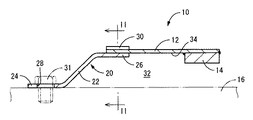
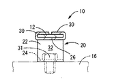
先ず、図1〜2には、本発明の一実施形態としてのダイナミックダンパ10の縦断面図と横断面図が示されている。このダイナミックダンパ10は、バネ部材12とマス部としてのマス金具14を含んで構成されており、バネ部材12によってマス金具14を振動部材(制振対象部材)16に対して連結支持せしめることによって、振動部材16に装着されるようになっている。そして、かかる装着状態下では、バネ部材12とマス金具14によって構成されるマス−バネ振動系が、主振動系たる振動部材16に対する副振動系として機能して、動的吸振器として制振効果を発揮し得るようになっている。
【0022】
より詳細には、バネ部材12は、略一定の肉厚寸法と幅寸法で広がる短冊状の平板形を有している。また、バネ部材12の長手方向一方の端部(図1中の左端部)には、取付金具20が固着されている。この取付金具20は、略一定厚さの長手板形状を有しており、長手方向中央部分がクランク状に屈曲せしめられて段差形状の立上部22が形成されている。そして、この立上部22を挟んで一方の端部側が平板形状の固定部24とされている一方、他方の端部側がかしめ部26とされている。また、固定部24には、ボルト孔28が形成されている一方、かしめ部26には、幅方向両側に延びる一対のかしめ片30,30が一体形成されている。
【0023】
そして、かしめ部26の上面に、バネ部材12の長手方向一方の端部が重ね合わされると共に、かしめ片30,30が屈曲せしめられて、かしめ部26がバネ部材12の端部を四面から抱き込むようにして密着せしめられることにより、バネ部材12の端部に取付金具20がかしめ固定されている。
【0024】
而して、取付金具20の固定部24が振動部材16の取付面に重ね合わされて、ボルト孔28に挿通される固定ボルト31で振動部材16に固着されることにより、ダイナミックダンパ10が振動部材16に装着されるようになっている。なお、立上部22は、ダイナミックダンパ10の装着状態下で、後述するマス金具14が振動部材16に干渉しない程度に、固定部24からの立ち上がり高さを小さく設定することが、ダイナミックダンパ10をコンパクトに構成する上で望ましい。
【0025】
また、バネ部材12は、ダイナミックダンパ10の振動部材16への装着状態下で、立上部22の立ち上がり高さよりも十分に大きな長さで、取付金具20のかしめ部26から振動部材16に沿うようにして略水平に延び出して形成されており、振動部材16とバネ部材12の対向面間に所定間隔の空間32が形成されるようになっている。
【0026】
更にまた、かかるバネ部材12における内側面(振動部材16との対向面)34には、延び出し方向の先端の自由端部分に対して、マス金具14が重ね合わされて溶接等で固着されている。なお、マス金具14は、ダイナミックダンパ10の振動部材16への装着状態下でバネ部材12が弾性変形せしめられた際に、振動部材16への干渉が回避され得るように、バネ部材12からの突出高さが、立上部22の突出高さよりも小さく設定されている。
【0027】
すなわち、上述の如く構成されたダイナミックダンパ10においては、バネ部材12が、長手方向一端側に固着された取付金具20において振動部材16に固定された片端支持の梁構造をもって構成されており、その自由端に対してマス金具14が取り付けられている。それにより、かかるダイナミックダンパ10は、全体として、主振動系たる振動部材16における板厚方向(図1,2中の略上下方向)の振動に関して、バネ部材12をバネとすると共に、該バネ部材12の先端に固着されたマス金具14をマスとして、1自由度の副振動系を構成するようになっている。
【0028】
ここにおいて、上述のバネ部材12は、振動部材16への装着状態下での加振に際して十分な強度を備えた制振合金であって、損失係数が0.05以上(対数減衰率としては0.15以上)からなる材料で形成されており、特に本実施形態では、株式会社セイシンによって製造されて制振合金の一種として市販されている「M2052」と称されるMn−20Cu−5Ni−2Feの双晶型制振合金によって形成されたバネ部材12が好適に採用される。なお、バネ部材12の強度は、20kgf/mm2 以上の引張強度を有するものが望ましく、それによって、自動車用のダイナミックダンパとしても、十分な強度と耐久性が実現可能となる。
【0029】
また、取付金具20は、バネ部材12よりも高強度の材料、例えば鉄鋼系材料で形成されており、全体としてバネ部材12よりも大きな剛性を発揮し得る形状や寸法を備えている。これにより、振動部材16への装着状態下では、取付金具20を略剛体として、実質的にバネ部材12だけが弾性変形せしめられるようになっている。
【0030】
このような構造とされたダイナミックダンパ10においては、その装着状態下、振動部材16に板厚方向の振動が生ぜしめられると、それが加振力としてバネ部材12に及ぼされて図中の上下方向に首振り状に剪断変形せしめられることにより一つの副振動系として作用する。それ故、かかる副振動系の固有振動数を、バネ部材12を主体として構成されたバネ系の動的ばね定数と、マス金具14を主体として構成されたマス系の質量とを調節して、振動部材16において防振すべき振動の周波数に対応させてチューニングすることにより、かかる防振すべき振動に対して有効な制振効果が発揮されることとなる。
【0031】
そこにおいて、かかる副振動系は、バネ系が、特性の温度依存性の小さい金属系材料で形成されたバネ部材12を主体として構成されていることから、自動車の一般的な使用条件下での温度変化領域(マイナス数十度〜プラス百℃の程度の温度領域)において、バネ系の動的ばね定数、ひいては副振動系の固有振動数の大幅な変化が回避されて、防振を目的とする振動に対して、有効な制振効果を安定して得ることが出来るのである。
【0032】
しかも、副振動系が加振された際には、バネ部材12自体の弾性変形によって大きな損失係数(ロスファクタ)が発揮されることから、副振動系のチューニング周波数域を挟んだ上下の周波数域においても振動状態の悪化が回避されることとなり、全体として広い周波数域に亘って良好な振動低減が実現され得るのである。加えて、バネ部材12が金属系材料で形成されていることから、その損失係数の温度変化に伴う変動が抑えられることとなり、温度変化の大きい環境下でも優れた制振特性が安定して発揮されることとなる。
【0033】
また、本実施形態のダイナミックダンパ10では、高いばね剛性を持つ金属系材料で形成されたバネ部材12によってバネ系が構成されていることに加えて、該バネ部材12自体が十分な損失係数を発揮し得ることから、従来のゴム弾性体でバネ系を構成したりゴム弾性体等からなる高減衰材を別途設ける場合に比して、全体をコンパクトに構成することが可能である。特に、本実施形態のように振動部材16の表面に沿って延びる形態の梁状のバネ部材12を採用することにより、振動部材16に沿った小さなスペースに極めて効率的にダイナミックダンパ10を配設することが可能となるのである。
【0034】
特に、本実施形態のダイナミックダンパ10においては、制振合金で形成されたバネ部材12が、取付金具20を介して、振動部材16に固定されることから、バネ部材12への応力集中が取付金具20で軽減され得ると共に、振動部材16に取り付けるための特別な加工をバネ部材12に施す必要がないことから、比較的に高価で加工が難しく、加工に起因する特性変化のおそれがある制振合金を採用した場合でも、副振動系による目的とする制振効果を有効に且つ安定して確保しつつ、目的とするダイナミックダンパ10が有利に実現され得るのである。
【0035】
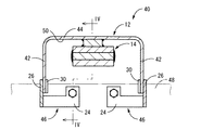
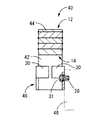
次に、図3〜4には、本発明の第二の実施形態としてのダイナミックダンパ40が、示されている。なお、本実施形態において、第一の実施形態と同様な構造とされた部材および部位については、それぞれ、第一の実施形態と同一の符号を付することにより、それらの詳細な説明を省略する。
【0036】
すなわち、本実施形態のダイナミックダンパ40において、副振動系を構成するバネ部材12は、略一定の肉厚寸法で延びる長手板形状を有しており、長手方向(図3中の左右方向)の両端部分がそれぞれ一方の面側(図3中の下方)に向かって屈曲した一対の立上部42,42とされていると共に、それら立上部42,42間の中央部分が、両立上部42,42の上端部を相互に繋ぐ平坦な天板部44とされている。要するに、本実施形態のバネ部材12は、一対の立上部42,42が互いに対向位置して略平行に立ち上がって形成されていると共に、それら両立上部42,42の突出先端部を相互に繋ぐようにして天板部44が一体形成されており、全体として、門形状とされている。
【0037】
また、バネ部材12における各立上部42,42の下端部には、取付金具46,46が固着されている。かかる取付金具46は、第一の実施形態の取付金具(20)と同様に、固定部24とかしめ部26を有しており、かしめ部26に一体形成されたかしめ片30,30で、バネ部材12の立上部42の下端部にかしめ固定される一方、固定部24のボルト孔28に挿通される固定ボルト31により、振動部材48に固着されるようになっている。
【0038】
そして、一対の取付金具46,46において振動部材48に固着されることにより、一対の立上部42,42および天板部44が、振動部材48との間に空間を形成するようにして、弾性変形可能に位置せしめられるようになっており、弾性変形可能とされた一対の立上部42,42と天板部44が、全体として、両端部で固定的に支持された両端固定の梁構造を構成している。
【0039】
また、バネ部材12の内側面50には、天板部44の長手方向略中央部分に位置して、第一の実施形態と同様なマス金具14が溶接等で固着されている。なお、本実施形態のマス金具14は、複数枚のマス板を重ね合わせて溶着等で一体化することにより、質量を調節した構造とされている。
【0040】
このような構造とされた本実施形態のダイナミックダンパ40においても、第一の実施形態と同様に、副振動系のバネが、特定の制振合金からなるバネ部材12で構成されていることから、かかる副振動系のばね定数とマス質量を適当に調節して、振動部材48において防振すべき振動に応じてチューニングすることにより、目的とする制振効果を、温度変化の悪影響を軽減乃至は回避しつつ安定して得ることが出来るのである。
【0041】
しかも、本実施形態のダイナミックダンパ40においても、バネ部材12の振動部材48への取付部が、バネ部材12と別体形成された取付金具46,46で形成されていることから、ダイナミックダンパ40を振動部材48に取り付けるための加工等による、制振合金からなるバネ部材12の特性への悪影響が軽減乃至は回避され得て、目的とする制振効果をより安定して得ることが出来るのである。
【0042】
また特に、本実施形態のダイナミックダンパ40は、バネ部材12における天板部44の厚さ方向(図3,4中の上下方向)の振動に対しては、天板部44の弾性変形が略剪断変形として有利に生ぜしめられると共に、それに直交する方向(図3中の左右方向)の振動に対しては、一対の立上部42,42の弾性変形が略剪断変形として有効に生ぜしめられることから、互いに直交するそれら二つの方向で、振動部材48に対する副振動系として有効に作用し得ることとなる。従って、それら各方向の固有振動数を適当にチューニングすることにより、振動部材48におけるそれぞれの方向の振動に対して、何れも有効な制振効果を得ることが可能となるのである。
【0043】
そして、このように複数の方向の振動に対して、それぞれ有効な制振効果を発揮し得る、本実施形態のダイナミックダンパ40にあっては、例えば、中心軸回りに回動せしめられる自動車用のステアリングホイール用のダイナミックダンパとしても有利に適用されることとなり、それによって、ステアリングホイールの振動を、その回動方向に拘わらず効果的に抑えることが可能となるのである。
【0044】
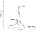
因みに、図5には、本実施形態のダイナミックダンパ40が装着された振動部材48を加振して、かかる振動部材48の振動加速度を測定することにより、ダイナミックダンパ40の制振特性の周波数依存性を測定した結果が、実施例として、示されている。なお、比較の為に、ダイナミックダンパ40が装着されていない振動部材を加振して、かかる振動部材の振動加速度を同一条件で測定し、その結果を、比較例として図5に併せ示す。
【0045】
図5に示された測定結果から明らかなように、本実施形態のダイナミックダンパ40は、振動部材の共振現象で問題となっていた周波数域(29〜30Hz程度)の振動レベルを大幅に抑え得ると共に、その前後の広い周波数域(20〜40Hz程度)で、良好な振動状態を発現せしめ得ることが認められる。
【0046】
以上、本発明の実施形態について詳述してきたが、これらはあくまでも例示であって、本発明は、かかる実施形態における具体的な記載によって何等限定的に解釈されるものでなく、当業者の知識に基づいて種々なる変更,修正,改良等を施した態様において実施され得るものであり、また、そのような実施態様が、本発明の趣旨を逸脱しない限り、何れも、本発明の範囲内に含まれるものであることは、言うまでもない。
【0047】
例えば、バネ部材12に対する取付金具20,46の固着構造は、例示の如きかしめ固定に限定されず、例えば、ロウ付け等の溶着の他、接着、或いはボルトやリベットによる固着構造等も採用可能である。
【0048】
さらに、第一の実施形態におけるバネ部材12や、第二の実施形態におけるバネ部材12(立上部42,42および天板部44)の長さ等の具体的寸法、更にマス金具14の大きさ(質量)等は、防振すべき振動周波数や振動レベル等に応じて適宜に変更されるものであって、限定されるものでない。そこにおいて、バネ部材12等の形状も、例えば振動部材16の取付面が湾曲形状等の異形状であれば、それに対応して湾曲形状等を採用し得る。
【0049】
また、ダイナミックダンパ10,40によって構成される副振動系の固有振動数は、振動部材16,48において制振すべき振動周波数に応じて決定されるものであり、必ずしも振動部材16,48の1次振動モード等の低次の振動モードにチューニングする必要はない。
【0050】
加えて、本発明に従う構造とされたダイナミックダンパは、自動車用のパネル部材やサブフレーム,ステアリングホイール等の他、振動が問題となる各種の装置等における各種の部材に対して装着され得る。
【0051】
【発明の効果】
上述の説明から明らかなように、本発明に従う構造とされたダイナミックダンパにおいては、副振動系のバネ系を構成するバネ部材が、特性の温度依存性が小さい合金材料で形成されていることから、大きな温度変化に晒された場合でも、目的とする振動に対して有効な制振効果を安定して得ることが出来ると共に、かかるバネ部材が、それ自体の弾性変形に際して大きな損失係数(ロスファクタ)を発揮し得ることから、全体として広い周波数域に亘って良好な振動低減が実現され得るのである。
【0052】
しかも、かかるダイナミックダンパは、高いばね剛性を持つ合金系のバネ部材が採用されていることに加えて、該バネ部材自体が大きな損失係数を発揮し得ることから、従来のゴム弾性体でバネ系を構成したりゴム弾性体等からなる減衰手段を別途設けていたダイナミックダンパに比して、全体をコンパクトに構成することが可能となる。
【0053】
加えて、本発明のダイナミックダンパにおいては、バネ部材の制振対象部材への取付部が、バネ部材と別体形成された取付金具で形成されていることから、ダイナミックダンパを制振対象部材に取り付けるための加工に際しての、制振合金からなるバネ部材の特性への悪影響が軽減乃至は回避され得るのであり、それ故、目的とする制振効果をより一層安定して得ることが出来るのである。
【図面の簡単な説明】
【図1】本発明の第一の実施形態としてのダイナミックダンパを示す縦断面図である。
【図2】図1におけるII−II断面図である。
【図3】本発明の第二の実施形態としてのダイナミックダンパを示す縦断面図である。
【図4】図3におけるIV−IV断面図である。
【図5】第二の実施形態のダイナミックダンパにおける制振特性の周波数依存性を測定した結果を、比較例と共に示すグラフである。
【符号の説明】
10 ダイナミックダンパ
12 バネ部材
14 マス金具
16 振動部材
20 取付金具
26 かしめ部
40 ダイナミックダンパ
42 立上部
44 天板部
46 取付金具
48 振動部材[0001]
【Technical field】
According to the present invention, the mass member is elastically supported via a spring member with respect to the member to be damped, thereby forming a sub-vibration system for the member to be damped which is a main vibration system, and The present invention relates to a dynamic damper that suppresses noise.
[0002]
[Background Art]
2. Description of the Related Art Conventionally, as a method of reducing vibration which is a problem in a vibration member (a member to be damped) such as a body in an automobile, a method of (1) attaching an asphalt sheet or a rubber sheet to the surface of the vibration member and damping material is used. And (2) a method of forming a dynamic damper by connecting and supporting a mass member to a vibration member via a spring member.
[0003]
However, in the vibration damping material of the above (1), the temperature dependency of the vibration damping effect of the asphalt sheet or the rubber sheet is large. For example, the temperature of the vibration member is affected by the internal combustion engine or the solar radiation as in the body of an automobile. When the temperature reaches 60 ° C. or higher, there is a problem that the vibration damping effect is greatly reduced. Moreover, in a low-order vibration mode such as the first-order vibration mode of the vibration member, there is a problem that it is difficult to obtain a sufficient vibration reduction effect due to a reduction in shear strain generated in the asphalt sheet.
[0004]
In the dynamic damper (2), since the rigidity of the rubber elastic body generally adopted as the spring member is small, the volume of the rubber elastic body must be increased in order to secure the rigidity. There is a problem that it is difficult to avoid a large dynamic damper. Moreover, the characteristic of the dynamic damper is tuned by setting the natural frequency of the sub-vibration system composed of its own mass-spring system to a specific vibration frequency range to be damped by the vibration member, It is difficult for an effective damping effect to be exerted only in a relatively narrow tuning frequency range, and in addition, the temperature dependence of the spring constant of the rubber elastic body is large. When exposed to a temperature difference of 60 ° C. or more due to changes in the environment or the environment, the tuning frequency deviates from the vibration frequency to be damped, and there is a problem that it is difficult to stably obtain an effective damping effect. is there.
[0005]
[Solution]
Here, the present invention has been made in view of the above-described circumstances, and the problem to be solved is that the present invention is compact and has a small temperature dependency of the vibration damping effect, over a large temperature change region. An object of the present invention is to provide a dynamic damper having a novel structure capable of stably exhibiting an effective vibration damping effect.
[0006]
[Solution]
Hereinafter, embodiments of the present invention made to solve such problems will be described. The components employed in each of the embodiments described below can be employed in any combination as much as possible. In addition, aspects or technical features of the present invention are not limited to those described below, but are described in the entire specification and drawings, or based on the inventive concept that can be understood by those skilled in the art from the descriptions. It should be understood that it is recognized on the basis of.
[0007]
According to a first aspect of the present invention, in a dynamic damper in which a mass part having a predetermined mass is elastically connected to and supported by a spring member with respect to a member to be damped, the vibration member having a loss coefficient of 0.05 or more is provided. While being formed of an alloy, a mounting member having a higher rigidity than the spring member is fixed to at least one end of the spring member, and the mounting member is fixedly attached to the vibration suppression target member. The mass portion is elastically displaceably supported by the spring member by being arranged in a beam shape.
[0008]
In such a dynamic damper of this aspect, an effective loss coefficient is realized by the spring member itself formed of the damping alloy, and it is necessary to separately provide a rubber elastic body or the like having a large temperature dependence of the spring constant. Therefore, the fluctuation of the spring constant of the sub-vibration system due to the temperature change can be suppressed, and the tuning frequency of the dynamic damper can be stabilized. Therefore, for example, the change of the environmental temperature such as the body panel of an automobile can be achieved. Even when the vibration member is mounted on a vibration member having a large width, it is possible to stably obtain an effective vibration damping effect with respect to vibration in a specific frequency range tuned in advance.
[0009]
In addition, the loss coefficient exhibited by the spring member formed of the vibration damping alloy does not vary greatly with temperature changes unlike rubber elastic bodies and asphalt, and in particular, by setting the loss coefficient to 0.05 or more. Therefore, the deterioration of the vibration state in the frequency range above and below the tuning frequency can be suppressed. Therefore, in the dynamic damper of the present embodiment, an effective vibration damping effect can be obtained in a wide frequency range regardless of the change in the environmental temperature. Can be done.
[0010]
In addition, in the dynamic damper of this aspect, since the spring member is formed of a vibration damping alloy having higher rigidity than the rubber elastic body, a sufficient spring rigidity can be ensured by a spring member having a small volume. In addition, since there is no need to separately provide a damping unit, an extremely compact dynamic damper can be realized as a whole.
[0011]
In the dynamic damper of this aspect, when the damping alloy is used for the spring member, the following specific structures (a), (b), and (c) are employed, whereby the elastic deformation is continuously repeated. Thus, the strength, durability, and reliability of the spring member can be secured at a high level.
(A) A portion that requires processing such as welding or formation of a bolt hole for attachment to a member to be damped is constituted by a mounting member that is separate from the spring member, so that it can be directly attached to the spring member itself. Processing is not required, and a change in the characteristics of the vibration damping alloy due to such processing is avoided.
(B) Since the supporting end of the spring member to which a particularly large stress acts upon the vibration is constituted by a mounting member separate from the spring member, the material, shape, structure, etc. of the mounting member can be changed by the spring member or the like. The design can be made without affecting the damping effect, and the durability of the dynamic damper is sufficiently ensured.
(C) The durability of the spring member itself is advantageously ensured by making the spring member elastically deformed at the time of vibration input into a beam shape and dispersing bending and shearing deformation in the longitudinal direction.
[0012]
The damping alloy used in the present embodiment may be appropriately selected from various kinds of damping alloys or known vibration damping alloys in consideration of the strength and durability required for the structural material. Any of those having various crystal structures such as a complex type, a ferromagnetic type, a transition type, and a twin type can be selected. Among them, manganese-based 20% copper, 5% % Of nickel and 2% of iron can be used as the vibration damping alloy of the present embodiment because it can achieve both a high loss factor and high strength.
[0013]
According to a second aspect of the present invention, in the dynamic damper according to the first aspect, the mounting member is fixed to one end of the spring member to form a beam structure supported at one end by the spring member. The mass member is provided at a free end of the spring member. In this embodiment, a cantilever-type spring member is configured, and a dynamic damper that can be efficiently operated with a particularly large amplitude in its primary vibration mode can be realized in a compact manner.
[0014]
Further, a third aspect of the present invention is the dynamic damper according to the second aspect, wherein the spring member is formed into a long flat plate shape, and the mounting member is fixed to one longitudinal end of the spring member, A separate mass metal fitting is fixed to the other end to form the mass portion. In this aspect, the shape of the spring member can be further simplified, and by adopting a separate mass metal fitting, a common spring member can be employed even when tuning is changed. Therefore, the manufacturing of the spring member can be facilitated and the cost can be reduced, and the characteristic change accompanying the processing of the spring member can be further advantageously avoided.
[0015]
According to a fourth aspect of the present invention, in the dynamic damper according to the first aspect, the mounting members are fixed to both ends in the longitudinal direction of the spring member, and both ends in the longitudinal direction of the spring member are bent. In a substantially gate shape including a pair of rising portions and a top plate portion, and the mass portion is provided on the top plate portion. In this aspect, the direction in which the pair of rising portions is advantageously elastically deformed and the direction in which the top plate portion is advantageously elastically deformed are substantially orthogonal to each other, and both directions function as auxiliary vibration systems. Therefore, a dynamic damper capable of exhibiting an effective vibration damping effect in two different directions can be realized. In this embodiment, preferably, the mass portion is provided so as to protrude from the inner peripheral surface of the top plate portion of the spring member having a gate-shaped structure into the central space. Further, a mass portion may be provided not only on the top plate portion but also on the rising portion.
[0016]
According to a fifth aspect of the present invention, in the dynamic damper according to any one of the first to fourth aspects, a caulking portion is integrally formed with the mounting member, and the spring member is held and fixed by the caulking portion. That is the feature. In this embodiment, the mounting member can be firmly fixed to the spring member without requiring any special processing on the spring member. On the other hand, a change in characteristics such as a loss coefficient of the spring member due to heat or plastic deformation is avoided, and a desired damping effect can be more stably obtained in the dynamic damper. .
[0017]
According to a sixth aspect of the present invention, in the dynamic damper according to any one of the first to fifth aspects, the spring member is formed of a vibration damping alloy having a tensile strength of 20 kgf / mm 2 or more. , Features. In this embodiment, the mass of the mass portion can be set to be sufficiently large. For example, it is possible to realize a dynamic damper that can be applied very advantageously to a vibration level generated in an automobile body or the like. Become. In addition, the tensile strength of 20 kgf / mm 2 or more in the vibration damping alloy can be advantageously realized by employing, for example, the twin type damping alloy of Mn-20Cu-5Ni-2Fe described above.
[0018]
Further, a seventh aspect of the present invention is the dynamic damper according to any one of the first to sixth aspects, wherein the member to be damped is a panel-shaped body, A characteristic feature is that the natural frequency of the vibration system thus configured is tuned to the vibration frequency of the primary mode of the panel-shaped body. In this embodiment, even if a vibration damping material having a conventional structure is used, it is difficult to effectively reduce vibration, and it is difficult to secure a mounting space for a dynamic damper. For example, a panel-shaped body such as a roof panel, a floor panel, and a door panel of an automobile In the above, a dynamic damper that can be advantageously applied with a compact arrangement space and that can exert an effective vibration damping effect with respect to vibrations in a plurality of modes including a low-order vibration mode such as a primary mode can be provided. It is.
[0019]
Note that, in this embodiment, an embodiment combined with the second embodiment described above is suitably adopted. In this case, a mounting member is provided at one end of the spring member so that the spring member has a beam structure supporting one end. The mounting member is raised from the panel-like body, and a spring member is provided so as to be spaced apart from the panel-like body and extend along the surface of the panel-like body. A mode in which the mass portion is protruded from the spring member so as to be positioned in the space formed between the opposing surfaces of the member is particularly preferably employed. That is, in such an embodiment, a dynamic damper that is disposed in a compact arrangement space while suppressing the protruding height from the panel-like body can be realized extremely advantageously.
[0020]
DETAILED DESCRIPTION OF THE INVENTION
Hereinafter, in order to clarify the present invention more specifically, embodiments of the present invention will be described in detail with reference to the drawings.
[0021]
First, FIGS. 1 and 2 show a longitudinal sectional view and a transverse sectional view of a dynamic damper 10 as one embodiment of the present invention. The dynamic damper 10 includes a spring member 12 and a mass fitting 14 as a mass portion. The mass fitting 14 is connected and supported by a spring member 12 to a vibration member (a member to be damped) 16. , Mounted on the vibration member 16. In such a mounted state, the mass-spring vibration system constituted by the spring member 12 and the mass metal fitting 14 functions as a sub-vibration system for the vibration member 16 which is a main vibration system, and has a vibration damping effect as a dynamic vibration absorber. Can be demonstrated.
[0022]
More specifically, the spring member 12 has a strip-like flat plate shape that spreads with substantially constant thickness and width dimensions. A mounting member 20 is fixed to one end (the left end in FIG. 1) of the spring member 12 in the longitudinal direction. The mounting bracket 20 has a longitudinal plate shape having a substantially constant thickness, and a central portion in the longitudinal direction is bent in a crank shape to form a step-shaped rising portion 22. One end portion of the rising portion 22 is formed as a flat fixing portion 24, and the other end portion is formed as a caulking portion 26. Further, a bolt hole 28 is formed in the fixing portion 24, while a pair of caulking pieces 30, 30 extending to both sides in the width direction are integrally formed in the caulking portion 26.
[0023]
One end in the longitudinal direction of the spring member 12 is overlapped on the upper surface of the caulking portion 26, and the caulking pieces 30, 30 are bent, so that the caulking portion 26 holds the end of the spring member 12 from all sides. The mounting member 20 is caulked and fixed to the end of the spring member 12 by being brought into close contact with each other.
[0024]
Thus, the fixing portion 24 of the mounting bracket 20 is superimposed on the mounting surface of the vibration member 16 and is fixed to the vibration member 16 with the fixing bolt 31 inserted into the bolt hole 28, so that the dynamic damper 10 is 16. It is noted that the rising portion 22 can be set to have a small rising height from the fixed portion 24 so that a mass metal fitting 14 described below does not interfere with the vibration member 16 when the dynamic damper 10 is mounted. This is desirable for compact construction.
[0025]
Further, the spring member 12 has a length sufficiently larger than the rising height of the rising portion 22 under the state where the dynamic damper 10 is attached to the vibration member 16, and extends along the vibration member 16 from the caulking portion 26 of the mounting bracket 20. The vibration member 16 is formed so as to extend substantially horizontally, and a space 32 having a predetermined interval is formed between the opposing surfaces of the vibration member 16 and the spring member 12.
[0026]
Furthermore, on the inner side surface (surface facing the vibration member 16) 34 of the spring member 12, the mass metal fitting 14 is superimposed and fixed by welding or the like to the free end portion at the tip end in the extending direction. . In addition, the mass metal fitting 14 is provided from the spring member 12 so that interference with the vibration member 16 can be avoided when the spring member 12 is elastically deformed while the dynamic damper 10 is mounted on the vibration member 16. The protrusion height is set smaller than the protrusion height of the rising portion 22.
[0027]
That is, in the dynamic damper 10 configured as described above, the spring member 12 is configured to have a one-end supported beam structure fixed to the vibration member 16 in the mounting bracket 20 fixed to one end in the longitudinal direction. A mass metal fitting 14 is attached to the free end. Accordingly, the dynamic damper 10 makes the spring member 12 a spring with respect to vibration in the thickness direction (substantially up and down directions in FIGS. 1 and 2) of the vibration member 16 as the main vibration system as a whole. The sub-vibration system having one degree of freedom is configured by using a mass metal fitting 14 fixed to the tip of the mass 12 as a mass.
[0028]
Here, the above-described spring member 12 is a vibration damping alloy having sufficient strength when vibrating in a state of being attached to the vibration member 16, and has a loss coefficient of 0.05 or more (a logarithmic damping rate of 0 Mn-20Cu-5Ni-2Fe referred to as "M2052" manufactured by Seishin Co., Ltd. and commercially available as a kind of damping alloy. The spring member 12 formed of the twin type vibration damping alloy is suitably adopted. The strength of the spring member 12 preferably has a tensile strength of 20 kgf / mm 2 or more, whereby sufficient strength and durability can be realized even as a dynamic damper for an automobile.
[0029]
Further, the mounting bracket 20 is formed of a material having a higher strength than the spring member 12, for example, a steel-based material, and has a shape and dimensions capable of exhibiting greater rigidity than the spring member 12 as a whole. Accordingly, in a state of being mounted on the vibration member 16, the mounting member 20 is substantially rigid, and substantially only the spring member 12 is elastically deformed.
[0030]
In the dynamic damper 10 having such a structure, when a vibration in the thickness direction is generated in the vibration member 16 in the mounted state, the vibration is applied to the spring member 12 as a vibrating force, and the vertical It acts as one sub-vibration system by being sheared and deformed in the direction of the head. Therefore, the natural frequency of the auxiliary vibration system is adjusted by adjusting the dynamic spring constant of the spring system mainly composed of the spring member 12 and the mass of the mass system mainly composed of the mass metal fitting 14, By tuning the vibration member 16 in accordance with the frequency of the vibration to be damped, an effective vibration damping effect is exerted on the vibration to be damped.
[0031]
In such a sub-vibration system, since the spring system is mainly composed of the spring member 12 formed of a metal material having a small temperature dependence of the characteristics, the sub-vibration system is used under a general use condition of an automobile. In the temperature change region (a temperature range of about minus several tens degrees to plus one hundred degrees Celsius), a large change in the dynamic spring constant of the spring system and, consequently, the natural frequency of the sub-vibration system is avoided, and the purpose is to prevent vibration. Thus, an effective vibration damping effect can be stably obtained with respect to the vibration that occurs.
[0032]
Moreover, when the sub-vibration system is vibrated, a large loss coefficient (loss factor) is exhibited by the elastic deformation of the spring member 12 itself. In this case, the deterioration of the vibration state can be avoided, and good vibration reduction can be realized over a wide frequency range as a whole. In addition, since the spring member 12 is formed of a metal-based material, the fluctuation of the loss coefficient due to the temperature change is suppressed, and the excellent vibration damping characteristics are stably exhibited even in an environment where the temperature change is large. Will be done.
[0033]
Further, in the dynamic damper 10 of the present embodiment, in addition to the fact that the spring system is constituted by the spring member 12 formed of a metal material having high spring rigidity, the spring member 12 itself has a sufficient loss coefficient. Therefore, the entire structure can be made more compact than when a spring system is formed of a conventional rubber elastic body or a high damping material made of a rubber elastic body or the like is separately provided. In particular, by employing the beam-shaped spring member 12 extending along the surface of the vibration member 16 as in the present embodiment, the dynamic damper 10 is extremely efficiently disposed in a small space along the vibration member 16. It is possible to do.
[0034]
In particular, in the dynamic damper 10 of the present embodiment, since the spring member 12 formed of the vibration damping alloy is fixed to the vibration member 16 via the mounting bracket 20, stress concentration on the spring member 12 is reduced. Since it can be reduced by the metal fitting 20 and it is not necessary to perform a special process for attaching to the vibration member 16 to the spring member 12, it is relatively expensive and difficult to process, and there is a possibility that the characteristics may change due to the process. Even when the vibration damping alloy is employed, the intended dynamic damper 10 can be advantageously realized while effectively and stably securing the intended vibration damping effect by the sub-vibration system.
[0035]
Next, FIGS. 3 and 4 show a dynamic damper 40 as a second embodiment of the present invention. In the present embodiment, members and parts having the same structure as in the first embodiment are denoted by the same reference numerals as those in the first embodiment, and a detailed description thereof will be omitted. .
[0036]
That is, in the dynamic damper 40 of the present embodiment, the spring member 12 constituting the sub-vibration system has an elongated plate shape extending with a substantially constant thickness, and is formed in the longitudinal direction (the left-right direction in FIG. 3). Both end portions are formed as a pair of rising portions 42, 42 bent toward one surface side (downward in FIG. 3), and a central portion between the rising portions 42, 42 is a pair of rising portions 42, 42. Are connected to each other to form a flat top plate portion 44. In short, the spring member 12 of the present embodiment is formed such that the pair of rising portions 42, 42 are formed so as to be substantially parallel to each other and face each other, and connect the protruding tips of the rising portions 42, 42 to each other. The top plate portion 44 is integrally formed, and has a gate shape as a whole.
[0037]
In addition, mounting brackets 46 are fixed to the lower ends of the rising portions 42 of the spring member 12. Like the mounting bracket (20) of the first embodiment, the mounting bracket 46 has a fixed portion 24 and a caulking portion 26. The caulking pieces 30, 30, which are integrally formed with the caulking portion 26, use a spring. While being fixed by caulking to the lower end of the rising portion 42 of the member 12, the member 12 is fixed to the vibration member 48 by the fixing bolt 31 inserted into the bolt hole 28 of the fixing portion 24.
[0038]
Then, by being fixed to the vibration member 48 at the pair of mounting brackets 46, 46, the pair of rising portions 42, 42 and the top plate 44 form a space between the vibration member 48 and the elastic member 42. The pair of rising portions 42, 42 and the top plate portion 44, which are elastically deformable and are elastically deformable, have a beam structure in which both ends are fixedly supported at both ends as a whole. Make up.
[0039]
A mass metal fitting 14 similar to that of the first embodiment is fixed to the inner side surface 50 of the spring member 12 at a substantially central portion in the longitudinal direction of the top plate portion 44 by welding or the like. The mass metal fitting 14 of the present embodiment has a structure in which a plurality of mass plates are overlapped and integrated by welding or the like to adjust the mass.
[0040]
Also in the dynamic damper 40 of this embodiment having such a structure, since the spring of the sub-vibration system is constituted by the spring member 12 made of a specific damping alloy, similarly to the first embodiment. By appropriately adjusting the spring constant and mass of the sub-vibration system and tuning the vibration in accordance with the vibration to be prevented by the vibrating member 48, the intended damping effect can be reduced by reducing the adverse effect of temperature change. Can be obtained stably while avoiding.
[0041]
In addition, also in the dynamic damper 40 of the present embodiment, since the mounting portion of the spring member 12 to the vibration member 48 is formed by the mounting brackets 46 formed separately from the spring member 12, the dynamic damper 40 is provided. Adverse effects on the characteristics of the spring member 12 made of a vibration damping alloy due to processing for attaching the vibration damping member to the vibration member 48 can be reduced or avoided, and the intended vibration damping effect can be obtained more stably. is there.
[0042]
Particularly, in the dynamic damper 40 of the present embodiment, the elastic deformation of the top plate portion 44 is substantially suppressed with respect to the vibration of the spring member 12 in the thickness direction of the top plate portion 44 (vertical direction in FIGS. 3 and 4). In addition to being advantageously generated as shearing deformation, elastic deformation of the pair of rising portions 42, 42 is effectively generated as substantially shearing deformation with respect to vibration in a direction perpendicular to the shearing deformation (horizontal direction in FIG. 3). Thus, the two directions orthogonal to each other can effectively act as a sub-vibration system for the vibration member 48. Therefore, by appropriately tuning the natural frequency in each direction, it is possible to obtain an effective vibration damping effect for the vibration of the vibration member 48 in each direction.
[0043]
The dynamic damper 40 of the present embodiment, which can exert an effective vibration damping effect with respect to vibrations in a plurality of directions as described above, is, for example, an automotive damper that is turned around a central axis. The present invention is also advantageously applied as a dynamic damper for a steering wheel, so that the vibration of the steering wheel can be effectively suppressed regardless of the rotation direction.
[0044]
Incidentally, FIG. 5 shows that the vibration member 48 to which the dynamic damper 40 of the present embodiment is mounted is vibrated, and the vibration acceleration of the vibration member 48 is measured. The results of measuring the properties are shown as examples. For comparison, a vibration member to which the dynamic damper 40 is not mounted was vibrated, and the vibration acceleration of the vibration member was measured under the same conditions. The result is also shown in FIG. 5 as a comparative example.
[0045]
As is clear from the measurement results shown in FIG. 5, the dynamic damper 40 of the present embodiment can significantly suppress the vibration level in the frequency range (about 29 to 30 Hz) which has been a problem due to the resonance phenomenon of the vibration member. At the same time, it is recognized that a favorable vibration state can be developed in a wide frequency range (about 20 to 40 Hz) before and after that.
[0046]
Although the embodiments of the present invention have been described above in detail, these are merely examples, and the present invention is not to be construed as being limited in any way by the specific description in such embodiments, and is understood by those skilled in the art. Various modifications, modifications, improvements, and the like can be made on the basis of the present invention, and any such embodiments fall within the scope of the present invention unless departing from the gist of the present invention. It goes without saying that it is included.
[0047]
For example, the fixing structure of the mounting members 20 and 46 to the spring member 12 is not limited to caulking and fixing as shown in the example. For example, in addition to welding such as brazing, bonding or a fixing structure using bolts or rivets can be adopted. is there.
[0048]
Furthermore, specific dimensions such as the length of the spring member 12 in the first embodiment, the length of the spring member 12 (the rising portions 42, 42 and the top plate 44) in the second embodiment, and the size of the mass metal fitting 14 (Mass) and the like are appropriately changed according to the vibration frequency and vibration level to be damped, and are not limited. In this case, the shape of the spring member 12 or the like may be a curved shape or the like corresponding to the shape of the mounting surface of the vibration member 16 if the mounting surface is a different shape such as a curved shape.
[0049]
The natural frequency of the sub-vibration system constituted by the dynamic dampers 10 and 40 is determined according to the vibration frequency to be damped by the vibration members 16 and 48, and is not necessarily one of the vibration members 16 and 48. It is not necessary to tune to a lower vibration mode such as the next vibration mode.
[0050]
In addition, the dynamic damper having the structure according to the present invention can be mounted on various members in various devices and the like in which vibration is a problem, such as a panel member for an automobile, a subframe, a steering wheel, and the like.
[0051]
【The invention's effect】
As is apparent from the above description, in the dynamic damper having the structure according to the present invention, the spring member forming the spring system of the sub-vibration system is formed of an alloy material having a small temperature dependency of the characteristic. In addition, even if the spring member is exposed to a large temperature change, it is possible to stably obtain an effective vibration damping effect with respect to a target vibration, and the spring member has a large loss coefficient (loss factor) when elastically deforming itself. ), Good vibration reduction can be realized over a wide frequency range as a whole.
[0052]
Moreover, such a dynamic damper employs an alloy-based spring member having high spring rigidity, and the spring member itself can exhibit a large loss coefficient. Compared to a dynamic damper in which a damping means made of a rubber elastic body or the like is separately provided.
[0053]
In addition, in the dynamic damper of the present invention, since the mounting portion of the spring member to the vibration damping target member is formed by a mounting member formed separately from the spring member, the dynamic damper is used as the vibration damping target member. The adverse effect on the characteristics of the spring member made of the damping alloy during the processing for mounting can be reduced or avoided, and therefore, the desired damping effect can be obtained more stably. .
[Brief description of the drawings]
FIG. 1 is a longitudinal sectional view showing a dynamic damper as a first embodiment of the present invention.
FIG. 2 is a sectional view taken along line II-II in FIG.
FIG. 3 is a longitudinal sectional view showing a dynamic damper as a second embodiment of the present invention.
FIG. 4 is a sectional view taken along line IV-IV in FIG. 3;
FIG. 5 is a graph showing a result of measuring a frequency dependence of a vibration damping characteristic of the dynamic damper according to the second embodiment, together with a comparative example.
[Explanation of symbols]
Reference Signs List 10 dynamic damper 12 spring member 14 mass fitting 16 vibrating member 20 mounting fitting 26 caulking section 40 dynamic damper 42 rising section 44 top plate section 46 mounting fitting 48 vibrating member