JP2004020070A - Heat pump type cold-hot water heater - Google Patents
Heat pump type cold-hot water heater Download PDFInfo
- Publication number
- JP2004020070A JP2004020070A JP2002176620A JP2002176620A JP2004020070A JP 2004020070 A JP2004020070 A JP 2004020070A JP 2002176620 A JP2002176620 A JP 2002176620A JP 2002176620 A JP2002176620 A JP 2002176620A JP 2004020070 A JP2004020070 A JP 2004020070A
- Authority
- JP
- Japan
- Prior art keywords
- refrigerant
- heat exchanger
- water
- during
- temperature
- Prior art date
- Legal status (The legal status is an assumption and is not a legal conclusion. Google has not performed a legal analysis and makes no representation as to the accuracy of the status listed.)
- Pending
Links
Images


Abstract
Description
【0001】
【発明の属する技術分野】
本発明は、水を冷却あるいは加熱するヒートポンプ式冷温水機に関し、特に、冷却運転および加熱運転において冷凍サイクルの安定性を維持した状態で高効率運転を可能としたものである。
【0002】
【従来の技術】
従来のヒートポンプ式冷温水機は、特開2000−320917号公報に記載されているように、冷却運転と加熱運転では四方切換弁の流路を切換えることによって冷媒(非共沸混合冷媒)の循環方向を逆転させ、利用側熱交換器であるプレート式熱交換器で水と非共沸混合冷媒を熱交換させて水を冷却もしくは加熱するようになっている。この場合、前記プレート式熱交換器における水と非共沸混合冷媒の流れ形式は、冷却運転時には並行流、加熱運転時には対向流となっている。
【0003】
また、特開2000−161806号公報に記載されている例では、凝縮器として作用し高圧冷媒の出口となる空気熱交換器出口またはプレート式熱交換器出口から流出する冷媒は、エコノマイザーにより過冷却(この場合、凝縮温度以下に冷却すること、つまり一旦液化された冷媒をさらに冷却することをいう。以下同じ)された後、膨張弁を通過する構成となっており、利用側熱交換器であるプレート式熱交換器の冷却媒体(水)と冷媒の流れ形式は、冷却運転時には対向流、加熱運転時には並行流となっている。
【0004】
【発明が解決しようとする課題】
冷凍サイクルの心臓部であるスクリュー圧縮機の信頼性を確保しつつ、高効率運転を行うためには、圧縮機吸入圧力(蒸発圧力)を高くして圧縮機の冷媒吸込量を多くすることや圧縮機効率の高い圧力条件での運転、および、プレート式熱交換器を有効活用するため、熱交換性能の低い過熱ガス域を少なくすること(冷媒の過熱度を小さくする)が重要であるが、一方では、スクリュー圧縮機の軸受焼損防止を図るためには、確実に圧縮機吸入冷媒の過熱を行い、液圧縮を避けることも重要である。しかし、膨張装置として従来から使用されている温度式自動膨張弁を用いた場合には、低負荷時に過熱度を維持しきれなくなり、圧縮機へ液戻りする場合がある。この意味においては吸入ガス過熱度を大きくとることが必要である。また、安定した冷凍サイクルの運転状態が得られることが重要である。
【0005】
しかしながら、上記従来例の特開2000−320917号公報の場合、冷媒が非共沸混合冷媒であり、しかもプレート式熱交換器の流れ形式が冷却運転時並行流のため、冷却運転時の熱交換性能がわるい。すなわち、非共沸混合冷媒は従来のR22等の単一冷媒と比較して特性が異なり、例えば、単一冷媒では蒸発開始から終了まで温度、圧力が一定なのに対し、非共沸混合冷媒は蒸発温度が一定ではなく温度勾配をもつため、利用側熱交換器すなわちプレート式熱交換器から取り出す冷水の温度を一定とすると、プレート式熱交換器出口の冷水温度以上には冷媒温度を高くできないため、吸入圧力(蒸発圧力)を下げて飽和温度を下げ、吸入ガス過熱度を確保する必要がある。特に冷却運転主体にヒートポンプ式冷温水機を使用する場合には、冷却運転時プレート式熱交換器の流れ形式を並行流とするのは好ましくない。さらに、冷凍サイクルが十分性能を発揮して安定した運転状態を得るには、膨張弁へ流入する冷媒は、流れが不安定な気液二相状態ではなく液単相状態が好ましい。しかし、この従来例の場合には、冷却運転および加熱運転において、凝縮器となる熱交換器(利用側熱交換器、空気側熱交換器)で冷媒を過冷却するようになっているが、凝縮域と比べ熱交換性能が悪い液単相域(過冷却域)は少なくする必要がある。
【0006】
前記特開2000−161806号公報の場合には、プレート式熱交換器の流れ形式は冷却運転時に対向流となっており、膨張弁へ流入する冷媒はエコノマイザーで過冷却されるためフラシュガス発生の心配がなく安定した運転状態が得られる。しかし、エコノマイザー用の熱交換器が別途必要であり、さらに過冷却させるためのもう一方側の回路(冷却する側の流体の管路)も必要となる。この回路として主回路から分岐した冷媒を流し、熱を奪って蒸発した冷媒を圧縮機の中間圧縮室へ流入させる場合には、圧縮機からの吐出量は吸入部から吸込まれる冷媒量に中間圧縮室へ流入する冷媒量が加算され増加するため、吐出圧力の上昇等を招き、サイクル性能に影響を及ぼす。外部の冷熱源を利用する場合には、そのためにさらにコストアップとなる。
【0007】
本発明の目的は、圧縮機の信頼性を確保しつつ高性能で安定性のある冷凍サイクル運転が可能なヒートポンプ式冷温水機を提供することにある。
【0008】
【課題を解決するための手段】
本発明の第1の手段は、上記目的を達成するため、冷媒ガスを圧縮するスクリュー圧縮機と、冷媒と空気を熱交換させる空気熱交換器と、冷温水負荷に供給される水と冷媒の間で熱交換させるプレート式熱交換器である水熱交換器と、系統内に循環する冷媒量を調節する冷媒量調整器と、凝縮液化された冷媒を減圧、膨張させる膨張装置と、前記スクリュー圧縮機の冷媒出側に接続されて冷媒循環方向を切り換える四方弁と、を含む機器を配管接続して冷凍サイクルを形成したヒートポンプ式冷温水機であって、前記水熱交換器を、その流れ形式が冷却運転時には対向流、加熱運転時には並行流となるように構成し、さらに、前記空気熱交換器を、冷却運転時に凝縮器、加熱運転時に蒸発器となる熱交換部と、凝縮液化された冷媒をさらに冷却する過冷却部とを一体に結合して構成したものである。
【0009】
上記構成によれば、冷却運転時の水熱交換器における流れ形式を対向流としたので、冷却運転時の水熱交換器出口の冷媒温度を高めることが可能となり、冷媒の温度効率が高い状態で運転できる。また、水熱交換器出口の冷媒温度を高めることで、冷媒の必要な過熱度を確保しながら冷媒の飽和温度、すなわち圧縮機吸入圧力を高めることができるから、圧縮機の性能が向上するし、必要な過熱度が維持されるので、液圧縮の恐れがなくなり、信頼性が確保される。さらに、膨張装置に導かれる前の冷媒を過冷却する過冷却部を設け、この過冷却部を、冷却運転時に凝縮器として動作する熱交換部と一体化して空気熱交換器としたので、膨張装置に導かれる冷媒が液単相状態となって、運転状態が安定すると共に、過冷却のための新たな冷却媒体やそのための管路を用意する必要がなく、コスト増加を少なくすることができる。
【0010】
前記過冷却部は、その冷媒流路の一端を前記冷媒量調整器を介して前記熱交換部の凝縮器として動作する場合の出側に接続し、他端を前記膨張装置に接続するようにしてもよい。
【0011】
また、前記冷媒量調整器を、前記膨張装置の一端と前記水熱交換器の冷媒流路を接続する管路に接続して設け、前記過冷却部は、その冷媒流路の一端を液溜めを介して前記熱交換部の凝縮器として動作する場合の出側に接続し、他端を前記膨張装置に接続するようにしてもよい。この場合、前記液溜めは、冷却運転時の外気温度変動に伴なう余剰冷媒を収納する。この構成によれば、冷却運転において例えば必要冷媒量が多くなる外気温度が低い低温条件下でも十分な冷媒量が確保でき、高効率運転が可能となる。
【0012】
さらに、膨張装置を電子膨張弁とし、この電子膨張弁の開度を、スクリュー圧縮機から吐出される冷媒ガスの温度が予め定められた設定値以下の場合は圧縮機吸入ガス過熱度が予め定められた加熱度範囲内となるように、また、スクリュー圧縮機から吐出される冷媒ガスの温度が前記設定値を超えて上昇した場合には、吐出される冷媒ガス温度が前記設定値以下となるように制御する電子膨張弁開度制御手段を備えてもよい。
【0013】
このように構成することで、冷媒流量が多い方のモードに合わせて膨張装置、すなわち電子膨張弁の容量を決めても、ほとんど流量0までの流量調整が可能であり、低負荷時でも圧縮機に吸入される冷媒の過熱度を確実に維持することができる。
【0014】
上記目的を達成する本発明の第2の手段は、冷媒ガスを圧縮するスクリュー圧縮機と、冷媒と空気を熱交換させる空気熱交換器と、冷温水負荷に供給される水と冷媒の間で熱交換させるプレート式熱交換器である水熱交換器と、系統内に循環する冷媒量を調節する冷媒量調整器と、凝縮液化された冷媒を減圧、膨張させる膨張装置と、前記スクリュー圧縮機の冷媒出側に接続されて冷媒循環方向を切り換える四方弁と、を含む機器を配管接続して冷凍サイクルを形成したヒートポンプ式冷温水機であって、前記水熱交換器は、冷媒と水が、冷却運転時には対向流、加熱運転時には並行流となるように構成され、前記空気熱交換器は、冷却運転時に凝縮器、加熱運転時に蒸発器となる熱交換部と、冷却運転時には凝縮液化された冷媒をさらに冷却し、加熱運転時には凝縮液化された冷媒を蒸発させる過冷却部が一体に結合されて構成されたものである。
【0015】
上記構成によれば、前記第1の手段と同様の効果が得られると共に、冷却運転時に一旦熱交換部で冷却された冷媒をさらに過冷却する過冷却部として用いられていた部分が、加熱運転時には冷媒を蒸発させる蒸発器として用いられるので、加熱運転時の蒸発能力が向上し、運転効率が高まる効果が得られる。
【0016】
【発明の実施の形態】
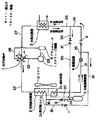
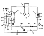
本発明の実施の形態を図1〜図8を参照して説明する。図1は本発明の実施の形態に係るヒートポンプ式冷温水機を示す冷凍サイクル系統図である。図示のヒートポンプ式冷温水機は、スクリュー圧縮機1と、スクリュー圧縮機1の吐出口に管路22でポートaを接続した四方切換弁7と、四方切換弁7のポートbに管路23で熱交換部(以下熱交換コイルという)2aの一端を接続した空気熱交換器2と、空気熱交換器2の前記熱交換コイル2aの他端に管路18を介して入り側を接続された逆止弁8と、逆止弁8の出側に管路24を介して接続された冷媒量調整器5と、冷媒量調整器5に管路20を介して冷媒流路の一端を接続され空気熱交換器2の一部をなす過冷却部(以下過冷却器という)2bと、過冷却器2bの冷媒流路の他端に管路21を介して接続された膨張装置4と、膨張装置4の他端に管路25を介して入り側を接続された逆止弁9と、逆止弁9の出側に管路26を介して冷媒流路の一端を接続された水熱交換器3と、水熱交換器3の冷媒流路の他端と前記四方切換弁7のポートdを接続する管路27と、前記四方切換弁7のポートcに管路28を介して接続されたアキュムレータ6と、アキュムレータ6とスクリュー圧縮機1の吸込み側を接続する管路29と、管路26と管路24を逆止弁10を介して接続する管路30と、管路25と管路18を逆止弁11を介して接続する管路19と、前記空気熱交換器2を風を送るファン12と、を含んで構成されている。
【0017】
逆止弁10,11は、それぞれ、管路26,25側を入り側、管路24,18側を出側として配置されている。
【0018】
四方弁7は、冷却運転時、ポートa〜b、ポートc〜dを連通する位置に操作され、加熱運転時、ポートa〜d、ポートb〜cを連通する位置に操作される。
【0019】
空気熱交換器2は、冷媒が流れる熱交換コイル2aを配置した部分と、同じく冷媒流路を備えた過冷却器2bを配置した部分からなり、両者が一体化されていて、共通のファン12から送風される空気流と冷媒がそれぞれ熱交換を行うようになっている。熱交換コイル2aは、冷却運転時は凝縮器として、また加熱運転時は蒸発器として、それぞれ機能する。
【0020】
また、水熱交換器3にはプレート式熱交換器が用いられており、冷媒と水の流れ形式は、冷却運転時には対向流、加熱運転時には並行流となるよう流路が構成されている。
【0021】
上記構成の装置の動作を次に説明する。
【0022】
冷却運転時には、スクリュー圧縮機1から吐出される高温高圧の冷媒ガスは四方切換弁7を通過後、空気熱交換器2の熱交換コイル2a(この場合、凝縮器として機能する)へ入り、ここで空気により冷却され凝縮液化する。その後、逆止弁8、冷媒量調整器5、空気熱交換器2の過冷却器2bを順次通り、過冷却器2bで過冷却された液冷媒は、膨張装置4で減圧され逆止弁9を通過後、水熱交換器3へ流入する。ここで水と熱交換が行われ、冷媒は水から蒸発熱を奪って蒸発し過熱ガスとなって流出し、四方切換弁7、アキュムレータ6を通り再度スクリュー圧縮機1へ吸入される。
【0023】
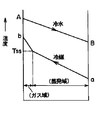
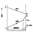
冷却運転時、水熱交換器3での水および冷媒(非共沸混合冷媒)の流れ形式は対向流となっており、温度パターンは図2に示されているように、冷媒出口温度bを冷水出口温度Bより高くすることが可能である。一方、並行流の場合の温度パターンは、図3に示されているように、冷媒出口温度bは冷水出口温度Bより高くすることはできない。対向流の場合、理論的には冷媒出口温度bを限りなく冷水入口温度Aまで近づけることが可能である。すなわち、対向流の方が冷媒側温度効率の高い状態で使用できる。
【0024】
冷媒出口温度bを高くできることは、出口冷媒の過熱度を同じ値に設定した場合、蒸発が終了する温度(飽和温度)を高くできることを意味し、飽和温度を高くできることは、蒸発圧力(吸入圧力)を高くできることである。したがって、並行流の場合と比べ、対向流では蒸発圧力(吸入圧力)を高くでき、この点でも性能向上を図ることができる。
【0025】
また、本冷凍サイクルでは、冷却運転時と加熱運転時の必要冷媒量の差分調整するための冷媒量調整器5が、空気熱交換器2の熱交換コイル(冷却運転時の凝縮器)2aと過冷却器2bの間に設けられているが、冷却運転時には、加熱運転時より必要冷媒量が多いため、加熱運転時には余剰冷媒を冷媒量調整器5に溜めることになる。すなわち、冷却運転時には空気熱交換器2の熱交換コイル2a出口冷媒の状態は気液二相状態であり、冷媒量調整器5内も気液二相状態となる。
【0026】
過冷却器2bがない場合には不安定な気液二相状態の冷媒が膨張装置4へ流入し、冷媒流量特性が不安定となり、冷凍サイクルの状態も不安定となるが、本実施の形態の冷凍サイクルでは、冷媒量調整器5から流出する気液二相冷媒は過冷却器2bで冷却され過冷却液(凝縮温度以下に冷却された液冷媒)となった後、膨張装置4へ流入するため安定した冷凍サイクル運転が可能となる。
【0027】
また、非共沸混合冷媒の場合には、膨張装置4に流入する冷媒を過冷却(凝縮温度以下に冷却)することで、蒸発器となる水熱交換器3(冷却運転時)の入口冷媒温度、または、空気熱交換器2の熱交換コイル2a(加熱運転時)の入口冷媒温度を低くできる。すなわち、入口冷媒温度を低くすることで、冷媒と水または空気との温度差を大きくでき、熱交換性能が向上する。
【0028】
加熱運転時には、冷却運転時とは逆方向の冷媒流れとなるように四方切換弁7によって流れ方向が切換えられる。すなわち、スクリュー圧縮機1から吐出される高温高圧の冷媒ガスは四方切換弁7を通過し水熱交換器3へ流入し、ここで水を加熱し冷媒は凝縮される。このとき、水熱交換器3での冷媒の流れと水の流れは並行流となる。凝縮された冷媒は逆止弁10、冷媒量調整器5を経由して過冷却器2bへ流入しファン12により送風される空気に冷却され過冷却液となって膨張装置4へ流入する。つぎに逆止弁11を通過後、空気熱交換器2の熱交換コイル(この場合、蒸発器として動作する)2aへ入り、冷媒は蒸発してガス状態となり、四方切換弁7、アキュムレータ6を通過し再度スクリュー圧縮機1に吸入される。このように、加熱運転においても冷却運転と同様に過冷却液の状態で膨張装置4へ冷媒が流入するため、安定した運転が得られる。
【0029】
本実施の形態によれば、冷却運転時の水熱交換器3における流れ形式を対向流としたので、水熱交換器出口の冷媒温度を高めることが可能となり、冷媒の温度効率が高い状態で運転できる。また、水熱交換器出口の冷媒温度を高めることで、冷媒の必要な過熱度を確保しながら冷媒の飽和温度、すなわち圧縮機吸入圧力を高めることができるから、圧縮機の性能が向上するし、必要な過熱度が維持されるので、液圧縮の恐れがなくなり、信頼性が確保される。さらに、膨張装置に導かれる前の冷媒を過冷却する過冷却器2bを設け、この過冷却器2bを、冷却運転時に凝縮器として動作する熱交換コイル2aと一体化して空気熱交換器2としたので、膨張装置に導かれる冷媒が液単相状態となって、運転状態が安定すると共に、過冷却器のための新たな冷却媒体やそのための管路を用意する必要がなく、コスト増加を少なくすることができる。
【0030】
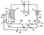
本発明の第2の実施の形態を図4を参照して説明する。図4は、本実施の形態のヒートポンプ式冷温水機の冷凍サイクル系統図を示す。第2の実施の形態が前記第1の実施の形態と異なるのは、冷媒量調整器5が逆止弁8の出側でなくて管路30の分岐部と水熱交換器3の間の管路26に分岐した配管に接続され、逆止弁8出側の管路24及び逆止弁10出側の管路30は、直接管路20に接続されている点である。他の構成は前記第1の実施の形態と同じなので、説明を省略する。
【0031】
本実施の形態では、冷却運転時、スクリュー圧縮機1で圧縮された冷媒は熱交換コイル2aで一旦凝縮液化され、次いで、冷媒量調整器5を経由することなく過冷却器2bに導かれて過冷却されたのち、膨張装置4で減圧されて水熱交換器3に流入する。このとき、冷媒の流れと水の流れは対向流となる。一方、加熱運転時は、スクリュー圧縮機1で圧縮された冷媒は水熱交換器3で凝縮液化され、次いで、過冷却器2bに流入して過冷却されたのち、膨張装置4で減圧されて熱交換コイル2aで蒸発する。このとき、水熱交換器3での冷媒の流れと水の流れは並行流となる。
【0032】
本実施の形態によれば、前記第1の実施の形態と同様の効果が得られる他、過熱運転時の余剰冷媒は、管路26に接続して配置されている冷媒量調整器5に貯えられるため、適正冷媒量の運転となり、高効率運転が可能となる。
【0033】
本発明の第3の実施の形態を図5を参照して説明する。図5は、本実施の形態のヒートポンプ式冷温水機の冷凍サイクル系統図を示す。第3の実施の形態が前記第2の実施の形態と異なるのは、熱交換コイル2aの他端と過冷却器2bの一端が管路18で直接接続され、逆止弁8〜11、管路19、20、24、30が省かれている点である。他の構成は前記第2の実施の形態と同じなので、説明を省略する。
【0034】
本実施の形態では、冷却運転時は、スクリュー圧縮機1で圧縮された冷媒は熱交換コイル2aで一旦凝縮液化され、次いで、過冷却器2bに導かれて過冷却されたのち、膨張装置4で減圧されて水熱交換器3に流入する。このとき、冷媒の流れと水の流れは対向流となる。一方、加熱運転時は、スクリュー圧縮機1で圧縮された冷媒は水熱交換器3で凝縮液化され、次いで膨張装置4で減圧されて過冷却器2bに導かれる。過冷却器2bに導かれた冷媒は、一部蒸発して気液2相となり、さらに熱交換コイル2aで蒸発して過熱ガス冷媒となってスクリュー圧縮機1に吸入される。
【0035】
本実施の形態によれば、冷却運転時の水熱交換器3における流れ形式を対向流としたので、水熱交換器出口の冷媒温度を高めることが可能となり、冷媒の温度効率が高い状態で運転できる。また、水熱交換器出口の冷媒温度を高めることで、冷媒の必要な過熱度を確保しながら冷媒の飽和温度、すなわち圧縮機吸入圧力を高めることができるから、圧縮機の性能が向上するし、必要な過熱度が維持されるので、液圧縮の恐れがなくなり、信頼性が確保される。さらに、冷却運転時に膨張装置に導かれる前の冷媒を過冷却する過冷却器2bを設け、この過冷却器2bを、冷却運転時に凝縮器として動作する熱交換コイル2aと一体化して空気熱交換器2としたので、冷却運転時、膨張装置に導かれる冷媒が液単相状態となって、運転状態が安定すると共に、過冷却器のための新たな冷却媒体やそのための管路を用意する必要がなく、コスト増加を少なくすることができる。また、冷却運転時に膨張装置に導かれる前の冷媒を過冷却する過冷却器2bが、加熱運転時には蒸発器の一部として用いられるので、加熱運転時の蒸発能力が向上し、高効率運転ができる。
【0036】
なお、本実施の形態でも、加熱運転時の余剰冷媒は、管路26に接続して配置されている冷媒量調整器5に貯えられるため、適正冷媒量の運転となり、高効率運転が可能となる。
【0037】
本発明の第4の実施の形態を図6を参照して説明する。図6は本実施の形態のヒートポンプ式冷温水機の冷凍サイクル系統図を示す。本実施の形態と前記第2の実施の形態の相違点は、本実施の形態では、管路18が液溜め31を介して熱交換コイル2aに接続されている点である。他の構成は前記第2の実施の形態と同じなので、説明を省略する。
【0038】
本実施の形態によれば、前記第2の実施の形態と同様の効果が得られるほか、冷却運転において例えば必要冷媒量が多くなる外気温度が低い低温条件下でも十分な冷媒量が確保でき、高効率運転が可能となる。したがって低外気温度時に併せて冷媒量を冷凍サイクル内に封入した場合、外気温度が比較的高い場合に過封入気味となり、高圧上昇による運転効率の低下や、安全確保のために冷凍サイクルに取りつけられる高圧遮断装置の作動による運転停止等の問題を回避できる。
【0039】
本発明の第5の実施の形態を図7を参照して説明する。図7は本実施の形態のヒートポンプ式冷温水機の冷凍サイクル系統図を示す。本実施の形態と前記第1の実施の形態の相違点は、図1に示されている冷凍サイクルにおいて、膨張装置として電子膨張弁13を用い、スクリュー圧縮機1の吸入冷媒ガスの温度Tsを検出する温度検出器15、及び圧力Psを検出する圧力検出器16を管路29に備え、スクリュー圧縮機1の吐出ガスの温度Tdを検出する温度検出器17を管路22に備え、これらの検出器15〜17の信号をもとに電子膨張弁13の開度を制御する電子膨張弁開度制御手段として電子膨張弁調節器14を備えた点である。他の構成は前記第1の実施の形態と同じであるので同一の符号を付して説明を省略する。
【0040】
電子膨張弁調節器14は、通常運転時にはスクリュー圧縮機吸入ガスの圧力検出結果から飽和ガス温度Tssを算出し、入力される吸入ガスの温度検出結果に基いて飽和ガス温度と吸入ガスの温度の差である吸入ガス過熱度が一定となるように電子膨張弁13の開度を制御し、吐出ガス温度がスクリュー圧縮機1の信頼性を確保するために設定される値(設定値Td0)達した場合には、吸入ガス過熱度一定制御から吐出ガス温度制御に移行する。
【0041】
前述したようにプレート式熱交換器を有効活用するためには、熱交換性能の低い過熱ガス域を少なくすること、すなわち冷媒ガス過熱度を小さくすることがが重要であるが、一方では、スクリュー圧縮機の軸受焼損防止を図るためには、確実に圧縮機吸入冷媒の過熱状態を維持することも重要である。従来から膨張装置として使用されている温度式自動膨張弁を用いた場合には、周知のように低負荷時に過熱度制御しきれなくなり(流量を絞りきれなくなり)、圧縮機へ液戻りする場合がある。このため定格負荷時の過熱度を小さく設定すると低負荷時にスクリュー圧縮機へ液戻りし、軸受潤滑等の目的で圧縮機内に封入されている冷凍機油より低粘度の液冷媒が軸受へ供給され軸受の焼損につながる場合がある。
【0042】
本実施の形態によれば、上述のようにスクリュー圧縮機吸入ガスの温度検出結果および圧力検出結果から飽和ガス温度を算出し、これらの温度差である過熱度を制御することが可能であるため、低負荷時においても過熱度制御が可能であり、また、蒸発器を有効活用するため過熱度を小さく制御することも可能である。この場合の電子膨張弁13の開度制御フローを図8に示す。
【0043】
電子膨張弁調節器14には、予め、吐出ガス温度の上限として設定値Td0が、吸入ガスの過熱度の基準値として設定値SH0±αが、それぞれ設定される。運転中、吸入圧力Ps、吸入ガス温度Ts、吐出ガス温度Tdが所定のサンプリング間隔でそれぞれの検出器で検出され、電子膨張弁調節器14に入力される。
【0044】
電子膨張弁調節器14では、まず吐出ガス温度Tdと設定値Td0を比較する。吐出ガス温度Td>設定値Td0なら電子膨張弁13の開度が増加され、水熱交換器3もしくは空気熱交換器2に供給される冷媒量が増加される。冷媒量の増加により、圧縮機吸入ガスの過熱度は低下し、したがって吐出ガス温度の低下がもたらされる。
【0045】
吐出ガス温度Td≦設定値Td0なら、次に吸入圧力における飽和ガス温度Tssを求め、この結果と吸入ガス温度Ts検出結果から吸入ガス過熱度SHを求める。吸入ガス過熱度SH>設定値SH0+αならば電子膨張弁13を開き、吸入ガス過熱度SH<設定値SH0−αならば電子膨張弁13を絞る方向に開度調整が行われる。
【0046】
設定値SH0−α≦吸入ガス過熱度SH≦設定値SH0+αならば、電子膨張弁13の開度はそのままに維持される。
【0047】
すなわち、吐出ガス温度Tdがスクリュー圧縮機1の信頼性を確保するために設定された吐出ガス温度設定値Td0より低い場合には、吸入ガス過熱度を設定範囲SH0±αに保つ制御が行われ、吐出ガス温度Tdが吐出ガス温度設定値Td0より高い場合には吸入ガス過熱度に関わりなく、吐出ガス温度を下げる制御が行われる。
【0048】
ヒートポンプサイクルにおいては、通常、冷却運転時と加熱運転時では系統内を循環する冷媒流量が異なる。前記第1の実施の形態のヒートポンプサイクルにおいても、冷媒流量が多くなる運転モードに合わせて膨張装置の容量を決める必要があるが、従来の温度式自動膨張弁では、冷媒流量が多くなる運転モードに合わせて大容量にすると、冷媒流量が少ない運転モードでの運転では負荷が小さい場合冷媒流量を絞りきれなくなり、圧縮機へ液戻りするため圧縮機の信頼性が低下する。逆に、冷媒流量が少なくなる運転モードに合わせて小容量の膨張弁とすると、冷媒流量が多くなるモードの運転において十分な性能が得られなくなる。このため、それぞれの運転モードに合わせた流量特性の異なる複数の膨張弁を用いることが多い。
【0049】
上述のように、温度式自動膨張弁は締め切り性がなく、冷媒流量制御範囲に制約があるが、電子膨張弁の場合には冷媒流量が多い方のモードに合わせて容量を決めても、ほとんど流量0までの流量調整が可能であり、低負荷時でも圧縮機に吸入される冷媒の過熱度を確実に維持することができる。
【0050】
本実施の形態によれば、前記第1の実施の形態における効果に加え、複数の膨張弁を用いることなく圧縮機への液戻りを防止でき、しかも冷却及び加熱の両運転モードにおいて、十分に性能を発揮することができる。
【0051】
【発明の効果】
本発明によれば、コストの大きな増加を招くことなく、スクリュー圧縮機の信頼性を確保しつつ高性能で安定性のある冷凍サイクル運転が可能となる。
【図面の簡単な説明】
【図1】本発明の第1の実施の形態を示すヒートポンプ式冷温水機の冷凍サイクル系統図である。
【図2】水熱交換器(プレート式熱交換器)の流れ形式が対向流の場合の冷水および冷媒の温度パターンである。
【図3】水熱交換器(プレート式熱交換器)の流れ形式が並行流の場合の冷水および冷媒の温度パターンである。
【図4】本発明の第2の実施の形態を示すヒートポンプ式冷温水機の冷凍サイクル系統図である。
【図5】本発明の第3の実施の形態を示すヒートポンプ式冷温水機の冷凍サイクル系統図である。
【図6】本発明の第4の実施の形態を示すヒートポンプ式冷温水機の冷凍サイクル系統図である。
【図7】本発明の第5の実施の形態を示す電子膨張弁を用いたヒートポンプ式冷温水機の冷凍サイクル系統図である。
【図8】図7に示す実施の形態における電子膨張弁開度調整フローである。
【符号の説明】
1 スクリュー圧縮機
2 空気熱交換器
2a 熱交換コイル
2b 過冷却器
3 水熱交換器
4 膨張装置
5 冷媒量調整器
6 アキュムレータ
7 四方切換弁
8 逆止弁
9 逆止弁
10 逆止弁
11 逆止弁
12 ファン
13 電子膨張弁
14 電子膨張弁調節器
15 温度検出器1
16 圧力検出器
17 温度検出器2
18〜30 管路
31 液溜め[0001]
TECHNICAL FIELD OF THE INVENTION
The present invention relates to a heat pump type chiller / heater that cools or heats water, and more particularly to a heat pump type chiller / heater that enables high-efficiency operation while maintaining stability of a refrigeration cycle in cooling operation and heating operation.
[0002]
[Prior art]
As described in Japanese Patent Application Laid-Open No. 2000-320917, a conventional heat pump chiller / heater circulates a refrigerant (non-azeotropic mixed refrigerant) by switching the flow path of a four-way switching valve in a cooling operation and a heating operation. The direction is reversed, and water is cooled or heated by exchanging heat between water and a non-azeotropic refrigerant mixture in a plate-type heat exchanger that is a use-side heat exchanger. In this case, the flow type of the water and the non-azeotropic mixed refrigerant in the plate heat exchanger is a parallel flow during the cooling operation and a counter flow during the heating operation.
[0003]
In the example described in Japanese Patent Application Laid-Open No. 2000-161806, refrigerant flowing from an air heat exchanger outlet or a plate-type heat exchanger outlet serving as a condenser and serving as a high-pressure refrigerant outlet is passed through an economizer. After being cooled (in this case, cooling to a temperature lower than the condensing temperature, that is, further cooling the once liquefied refrigerant, the same applies hereinafter), the refrigerant passes through an expansion valve, and is used as a use-side heat exchanger. The flow type of the cooling medium (water) and the refrigerant in the plate heat exchanger is a counter flow during the cooling operation and a parallel flow during the heating operation.
[0004]
[Problems to be solved by the invention]
In order to operate the screw compressor, which is the heart of the refrigeration cycle, with high reliability while maintaining high reliability, it is necessary to increase the compressor suction pressure (evaporation pressure) and increase the refrigerant suction amount of the compressor. It is important to reduce the superheated gas area with low heat exchange performance (reduce the degree of superheat of the refrigerant) in order to operate the compressor under high pressure conditions and to effectively use the plate heat exchanger. On the other hand, in order to prevent bearing burnout of the screw compressor, it is also important to surely overheat the refrigerant sucked into the compressor and avoid liquid compression. However, when a conventional temperature-type automatic expansion valve is used as the expansion device, the superheat degree cannot be maintained at a low load, and the liquid may return to the compressor. In this sense, it is necessary to increase the degree of superheat of the suction gas. It is important that a stable operating state of the refrigeration cycle is obtained.
[0005]
However, in the case of JP 2000-320917 A, the refrigerant is a non-azeotropic mixed refrigerant, and since the flow type of the plate heat exchanger is a parallel flow during the cooling operation, the heat exchange during the cooling operation is performed. Poor performance. That is, non-azeotropic mixed refrigerants have different characteristics as compared with conventional single refrigerants such as R22. For example, the temperature and pressure of a single refrigerant are constant from the start to the end of evaporation, whereas the non-azeotropic mixed refrigerant is evaporated. Since the temperature is not constant but has a temperature gradient, if the temperature of the chilled water taken out from the use-side heat exchanger, that is, the plate-type heat exchanger is kept constant, the refrigerant temperature cannot be higher than the chilled water temperature at the outlet of the plate-type heat exchanger. Further, it is necessary to lower the saturation temperature by lowering the suction pressure (evaporation pressure) to secure the degree of superheat of the suction gas. In particular, when a heat pump chiller / heater is used mainly for the cooling operation, it is not preferable to make the flow type of the plate heat exchanger parallel during the cooling operation. Further, in order for the refrigeration cycle to exhibit sufficient performance to obtain a stable operation state, the refrigerant flowing into the expansion valve is preferably in a liquid single-phase state instead of a gas-liquid two-phase state in which the flow is unstable. However, in the case of the conventional example, in the cooling operation and the heating operation, the refrigerant is supercooled by the heat exchanger (the use-side heat exchanger and the air-side heat exchanger) which is a condenser. It is necessary to reduce the number of liquid single-phase regions (supercooling regions) having poor heat exchange performance compared to the condensing regions.
[0006]
In the case of Japanese Patent Application Laid-Open No. 2000-161806, the flow type of the plate heat exchanger is a counter flow during the cooling operation, and the refrigerant flowing into the expansion valve is supercooled by the economizer, so that flash gas is generated. A stable operating state can be obtained without worrying about However, a heat exchanger for the economizer is separately required, and a circuit on the other side (a fluid passage on the cooling side) for supercooling is also required. When the refrigerant branched from the main circuit flows as this circuit, and the refrigerant evaporated by absorbing heat flows into the intermediate compression chamber of the compressor, the discharge amount from the compressor is intermediate with the refrigerant amount sucked from the suction part. Since the amount of the refrigerant flowing into the compression chamber is added and increased, the discharge pressure is increased and the cycle performance is affected. If an external heat source is used, the cost is further increased.
[0007]
SUMMARY OF THE INVENTION An object of the present invention is to provide a heat pump type chiller / heater capable of performing a high performance and stable refrigeration cycle operation while ensuring the reliability of a compressor.
[0008]
[Means for Solving the Problems]
In order to achieve the above object, a first means of the present invention includes a screw compressor for compressing a refrigerant gas, an air heat exchanger for exchanging heat between refrigerant and air, and a method for cooling water and refrigerant supplied to a cold / hot water load. A water heat exchanger that is a plate-type heat exchanger for exchanging heat between the refrigerant, a refrigerant amount regulator that regulates the amount of refrigerant circulating in the system, a decompressed and liquefied refrigerant, an expansion device that expands the refrigerant, and the screw. A four-way valve connected to the refrigerant outlet side of the compressor to switch the refrigerant circulation direction, and a heat pump type chiller / heater in which a refrigeration cycle is formed by connecting equipment including a pipe, wherein the water heat exchanger has a The type is configured to be a counter flow during the cooling operation and a parallel flow during the heating operation, and further, the air heat exchanger is a condenser during the cooling operation, a heat exchange unit that becomes an evaporator during the heating operation, and is condensed and liquefied. Refrigerant And a supercooling part that is constructed by integrally joined.
[0009]
According to the above configuration, since the flow type in the water heat exchanger during the cooling operation is set to the counterflow, the refrigerant temperature at the outlet of the water heat exchanger during the cooling operation can be increased, and the temperature efficiency of the refrigerant is high. You can drive with. Also, by increasing the refrigerant temperature at the outlet of the water heat exchanger, the saturation temperature of the refrigerant, that is, the compressor suction pressure can be increased while securing the necessary degree of superheat of the refrigerant, so that the performance of the compressor is improved. Since the required degree of superheat is maintained, there is no danger of liquid compression and reliability is ensured. Furthermore, a supercooling unit for supercooling the refrigerant before being guided to the expansion device is provided, and this supercooling unit is integrated with a heat exchange unit that operates as a condenser during a cooling operation to form an air heat exchanger. The refrigerant guided to the device is in a liquid single-phase state, so that the operation state is stabilized, and it is not necessary to prepare a new cooling medium for supercooling and a pipeline for the same, thereby reducing the cost increase. .
[0010]
The supercooling unit is configured such that one end of the refrigerant flow path is connected to the outlet side of the heat exchange unit when operating as a condenser via the refrigerant amount regulator, and the other end is connected to the expansion device. You may.
[0011]
Further, the refrigerant amount regulator is provided by connecting one end of the expansion device to a pipe connecting the refrigerant flow passage of the water heat exchanger, and the supercooling unit is configured to store one end of the refrigerant flow passage in a liquid reservoir. May be connected to the outlet side of the heat exchange unit when it operates as a condenser, and the other end may be connected to the expansion device. In this case, the liquid reservoir stores an excess refrigerant due to a change in outside air temperature during the cooling operation. According to this configuration, in the cooling operation, for example, a sufficient amount of refrigerant can be ensured even under a low-temperature condition where the outside air temperature is low where the required amount of refrigerant increases, and high-efficiency operation can be performed.
[0012]
Further, the expansion device is an electronic expansion valve, and the degree of opening of the electronic expansion valve is determined in advance when the temperature of the refrigerant gas discharged from the screw compressor is equal to or less than a predetermined set value. So that the temperature of the refrigerant gas discharged from the screw compressor rises above the set value, so that the temperature of the discharged refrigerant gas becomes equal to or lower than the set value. An electronic expansion valve opening control means for controlling the opening degree may be provided.
[0013]
With such a configuration, even if the expansion device, that is, the capacity of the electronic expansion valve is determined in accordance with the mode in which the refrigerant flow rate is larger, the flow rate can be almost adjusted to 0, and the compressor can be operated even at a low load. It is possible to reliably maintain the degree of superheat of the refrigerant sucked into the tank.
[0014]
A second means of the present invention for achieving the above object is a screw compressor for compressing a refrigerant gas, an air heat exchanger for exchanging heat between the refrigerant and air, and a water and refrigerant supplied to a cold / hot water load. A water heat exchanger that is a plate heat exchanger for performing heat exchange, a refrigerant amount regulator that regulates an amount of refrigerant circulating in the system, an expansion device that decompresses and expands condensed and liquefied refrigerant, and the screw compressor. And a four-way valve that is connected to the refrigerant outlet side to switch the refrigerant circulation direction, and a heat pump type chiller / heater in which a refrigeration cycle is formed by connecting equipment including a pipe, wherein the refrigerant and water are The air heat exchanger is configured to have a counter flow during the cooling operation and a parallel flow during the heating operation. Refrigerant And, supercooling part of evaporating during the heating operation is condensed and liquefied refrigerant is one that was constructed by integrally joined.
[0015]
According to the above configuration, the same effect as the first means is obtained, and the portion used as the supercooling unit for further subcooling the refrigerant once cooled in the heat exchange unit during the cooling operation is changed to the heating operation. Sometimes, it is used as an evaporator for evaporating the refrigerant, so that the evaporating ability during the heating operation is improved, and the effect of increasing the operation efficiency is obtained.
[0016]
BEST MODE FOR CARRYING OUT THE INVENTION
An embodiment of the present invention will be described with reference to FIGS. FIG. 1 is a refrigeration cycle system diagram showing a heat pump type chiller / heater according to an embodiment of the present invention. The illustrated heat pump chiller / heater has a screw compressor 1, a four-way switching valve 7 having a port a connected to a discharge port of the screw compressor 1 via a
[0017]
The
[0018]
The four-way valve 7 is operated at a position communicating with the ports a to b and the ports c to d during the cooling operation, and is operated at a position communicating the ports a to d and the ports b to c during the heating operation.
[0019]
The
[0020]
In addition, a plate heat exchanger is used for the
[0021]
Next, the operation of the apparatus having the above configuration will be described.
[0022]
During the cooling operation, the high-temperature and high-pressure refrigerant gas discharged from the screw compressor 1 passes through the four-way switching valve 7 and then enters the
[0023]
During the cooling operation, the flow forms of water and the refrigerant (non-azeotropic mixed refrigerant) in the
[0024]
The fact that the refrigerant outlet temperature b can be increased means that, when the superheat degree of the outlet refrigerant is set to the same value, the temperature at which evaporation ends (saturation temperature) can be increased. ) Can be higher. Therefore, as compared with the case of the parallel flow, the evaporation pressure (suction pressure) can be increased in the counter flow, and the performance can be improved also in this respect.
[0025]
In this refrigeration cycle, the
[0026]
Without the
[0027]
In the case of a non-azeotropic mixed refrigerant, the refrigerant flowing into the
[0028]
During the heating operation, the flow direction is switched by the four-way switching valve 7 so that the refrigerant flows in a direction opposite to that in the cooling operation. That is, the high-temperature and high-pressure refrigerant gas discharged from the screw compressor 1 passes through the four-way switching valve 7 and flows into the
[0029]
According to the present embodiment, since the flow type in the
[0030]
A second embodiment of the present invention will be described with reference to FIG. FIG. 4 shows a refrigeration cycle system diagram of the heat pump type chiller / heater of the present embodiment. The second embodiment is different from the first embodiment in that the
[0031]
In the present embodiment, during the cooling operation, the refrigerant compressed by the screw compressor 1 is once condensed and liquefied by the
[0032]
According to the present embodiment, in addition to the same effect as that of the first embodiment, the surplus refrigerant during the superheating operation is stored in the
[0033]
A third embodiment of the present invention will be described with reference to FIG. FIG. 5 shows a refrigeration cycle system diagram of the heat pump water heater / heater of the present embodiment. The third embodiment is different from the second embodiment in that the other end of the
[0034]
In the present embodiment, during the cooling operation, the refrigerant compressed by the screw compressor 1 is once condensed and liquefied by the
[0035]
According to the present embodiment, since the flow type in the
[0036]
In this embodiment, too, the surplus refrigerant during the heating operation is stored in the
[0037]
A fourth embodiment of the present invention will be described with reference to FIG. FIG. 6 shows a refrigeration cycle system diagram of the heat pump type chiller / heater of the present embodiment. The difference between the present embodiment and the second embodiment is that, in the present embodiment, the
[0038]
According to the present embodiment, in addition to the same effects as in the second embodiment, a sufficient amount of refrigerant can be ensured even in a low temperature condition where the outside air temperature is low, for example, where the required amount of refrigerant increases in the cooling operation, High efficiency operation becomes possible. Therefore, when the refrigerant amount is sealed in the refrigeration cycle at the same time as the low outside air temperature, it tends to be overfilled when the outside air temperature is relatively high, and it is installed in the refrigeration cycle to reduce operating efficiency due to high pressure rise and to ensure safety Problems such as operation stop due to operation of the high-pressure cut-off device can be avoided.
[0039]
A fifth embodiment of the present invention will be described with reference to FIG. FIG. 7 shows a refrigeration cycle system diagram of the heat pump type chiller / heater of the present embodiment. The difference between this embodiment and the first embodiment is that, in the refrigeration cycle shown in FIG. 1, the
[0040]
During normal operation, the electronic
[0041]
As described above, in order to effectively utilize the plate-type heat exchanger, it is important to reduce the superheated gas region having a low heat exchange performance, that is, to reduce the degree of superheat of the refrigerant gas. In order to prevent bearing burnout of the compressor, it is also important to reliably maintain the superheated state of the compressor suction refrigerant. As is well known, when using a temperature-type automatic expansion valve conventionally used as an expansion device, it is difficult to control the degree of superheat at a low load (cannot reduce the flow rate), and the liquid may return to the compressor. is there. Therefore, if the degree of superheat at the rated load is set to a small value, the liquid returns to the screw compressor at a low load, and a liquid refrigerant having a lower viscosity than the refrigerating machine oil sealed in the compressor is supplied to the bearing for lubrication of the bearing. May lead to burning of the steel.
[0042]
According to the present embodiment, as described above, it is possible to calculate the saturation gas temperature from the temperature detection result and the pressure detection result of the suction gas of the screw compressor, and to control the degree of superheat, which is the difference between these temperatures. The superheat degree can be controlled even at a low load, and the superheat degree can be controlled to be small in order to effectively use the evaporator. FIG. 8 shows an opening control flow of the
[0043]
The electronic
[0044]
In the electronic
[0045]
Discharge gas temperature Td ≦ set value Td 0 Then, the saturation gas temperature Tss at the suction pressure is obtained, and the superheat degree SH of the suction gas is obtained from the result and the detection result of the suction gas temperature Ts. Intake gas superheat degree SH> set value SH 0 If + α, the
[0046]
Set value SH 0 −α ≦ superheat degree of intake gas SH ≦ set value SH 0 If it is + α, the opening of the
[0047]
That is, the discharge gas temperature Td is a discharge gas temperature set value Td set to secure the reliability of the screw compressor 1. 0 If it is lower, the superheat degree of the intake gas is set to the set range SH. 0 Control is performed to maintain ± α, and the discharge gas temperature Td is set to the discharge gas temperature set value Td. 0 When the temperature is higher, control is performed to lower the discharge gas temperature regardless of the degree of superheat of the suction gas.
[0048]
In the heat pump cycle, the flow rate of the refrigerant circulating in the system usually differs between the cooling operation and the heating operation. In the heat pump cycle of the first embodiment as well, it is necessary to determine the capacity of the expansion device in accordance with the operation mode in which the refrigerant flow rate increases. When the load is small in the operation in the operation mode in which the flow rate of the refrigerant is small, the flow rate of the refrigerant cannot be reduced sufficiently, and the liquid returns to the compressor, thereby lowering the reliability of the compressor. Conversely, if the expansion valve has a small capacity in accordance with the operation mode in which the refrigerant flow rate decreases, sufficient performance cannot be obtained in the operation in the mode in which the refrigerant flow rate increases. For this reason, a plurality of expansion valves having different flow characteristics according to each operation mode are often used.
[0049]
As described above, the temperature-type automatic expansion valve has no shut-off property and has a limitation on the refrigerant flow rate control range. The flow rate can be adjusted up to a flow rate of 0, and the degree of superheat of the refrigerant drawn into the compressor can be reliably maintained even at a low load.
[0050]
According to the present embodiment, in addition to the effects of the first embodiment, liquid return to the compressor can be prevented without using a plurality of expansion valves, and in both the cooling and heating operation modes, it is sufficient. Performance can be demonstrated.
[0051]
【The invention's effect】
Advantageous Effects of Invention According to the present invention, a high-performance and stable refrigeration cycle operation can be performed while ensuring the reliability of a screw compressor without causing a large increase in cost.
[Brief description of the drawings]
FIG. 1 is a refrigeration cycle system diagram of a heat pump chiller / heater according to a first embodiment of the present invention.
FIG. 2 shows the temperature patterns of the cold water and the refrigerant when the flow type of the water heat exchanger (plate type heat exchanger) is countercurrent.
FIG. 3 shows temperature patterns of cold water and refrigerant when the flow type of the water heat exchanger (plate type heat exchanger) is a parallel flow.
FIG. 4 is a refrigeration cycle system diagram of a heat pump type chiller / heater according to a second embodiment of the present invention.
FIG. 5 is a refrigeration cycle system diagram of a heat pump type chiller / heater showing a third embodiment of the present invention.
FIG. 6 is a refrigeration cycle system diagram of a heat pump chiller / heater showing a fourth embodiment of the present invention.
FIG. 7 is a refrigeration cycle system diagram of a heat pump chiller / heater using an electronic expansion valve according to a fifth embodiment of the present invention.
FIG. 8 is an electronic expansion valve opening adjustment flow in the embodiment shown in FIG. 7;
[Explanation of symbols]
1 Screw compressor
2 Air heat exchanger
2a Heat exchange coil
2b Subcooler
3 Water heat exchanger
4 Expansion device
5 Refrigerant amount regulator
6 Accumulator
7 Four-way switching valve
8 Check valve
9 Check valve
10 Check valve
11 Check valve
12 fans
13 Electronic expansion valve
14 Electronic expansion valve controller
15 Temperature detector 1
16 Pressure detector
17
18-30 pipe
31 Reservoir
Claims (5)
Priority Applications (1)
| Application Number | Priority Date | Filing Date | Title |
|---|---|---|---|
| JP2002176620A JP2004020070A (en) | 2002-06-18 | 2002-06-18 | Heat pump type cold-hot water heater |
Applications Claiming Priority (1)
| Application Number | Priority Date | Filing Date | Title |
|---|---|---|---|
| JP2002176620A JP2004020070A (en) | 2002-06-18 | 2002-06-18 | Heat pump type cold-hot water heater |
Publications (2)
| Publication Number | Publication Date |
|---|---|
| JP2004020070A true JP2004020070A (en) | 2004-01-22 |
| JP2004020070A5 JP2004020070A5 (en) | 2005-08-11 |
Family
ID=31174871
Family Applications (1)
| Application Number | Title | Priority Date | Filing Date |
|---|---|---|---|
| JP2002176620A Pending JP2004020070A (en) | 2002-06-18 | 2002-06-18 | Heat pump type cold-hot water heater |
Country Status (1)
| Country | Link |
|---|---|
| JP (1) | JP2004020070A (en) |
Cited By (9)
| Publication number | Priority date | Publication date | Assignee | Title |
|---|---|---|---|---|
| KR100606277B1 (en) | 2004-12-29 | 2006-08-01 | 위니아만도 주식회사 | heat-pump air-conditioner |
| JP2006242524A (en) * | 2005-03-07 | 2006-09-14 | Sanyo Electric Co Ltd | Air conditioner |
| KR100728683B1 (en) | 2005-08-24 | 2007-06-15 | 엘지전자 주식회사 | Air-conditioner for both heating and cooling |
| KR100843799B1 (en) | 2006-11-28 | 2008-07-04 | 김성수 | The Cooling System |
| JP2010151390A (en) * | 2008-12-25 | 2010-07-08 | Orion Mach Co Ltd | Temperature adjusting device |
| JP2011190982A (en) * | 2010-03-15 | 2011-09-29 | Honda Motor Co Ltd | Heat exchanger |
| CN104833172A (en) * | 2015-03-16 | 2015-08-12 | 泰兴市东圣食品科技有限公司 | Material liquid cooling device |
| KR101594038B1 (en) * | 2008-06-04 | 2016-02-15 | 이호영 | heat-pump type system for suppling cold and hot water |
| WO2022068950A1 (en) * | 2021-04-16 | 2022-04-07 | 青岛海尔空调器有限总公司 | Room temperature adjusting device |
Citations (5)
| Publication number | Priority date | Publication date | Assignee | Title |
|---|---|---|---|---|
| JPS61153454A (en) * | 1984-12-27 | 1986-07-12 | 松下電器産業株式会社 | Solar-heat utilizing water heater |
| JPH0342966U (en) * | 1989-08-30 | 1991-04-23 | ||
| JPH06123499A (en) * | 1992-10-12 | 1994-05-06 | Hitachi Ltd | Air conditioner |
| JP2000320917A (en) * | 1999-05-06 | 2000-11-24 | Hitachi Ltd | Heat pump cold/hot water machine |
| JP2001174075A (en) * | 1999-12-14 | 2001-06-29 | Daikin Ind Ltd | Refrigerating device |
-
2002
- 2002-06-18 JP JP2002176620A patent/JP2004020070A/en active Pending
Patent Citations (5)
| Publication number | Priority date | Publication date | Assignee | Title |
|---|---|---|---|---|
| JPS61153454A (en) * | 1984-12-27 | 1986-07-12 | 松下電器産業株式会社 | Solar-heat utilizing water heater |
| JPH0342966U (en) * | 1989-08-30 | 1991-04-23 | ||
| JPH06123499A (en) * | 1992-10-12 | 1994-05-06 | Hitachi Ltd | Air conditioner |
| JP2000320917A (en) * | 1999-05-06 | 2000-11-24 | Hitachi Ltd | Heat pump cold/hot water machine |
| JP2001174075A (en) * | 1999-12-14 | 2001-06-29 | Daikin Ind Ltd | Refrigerating device |
Cited By (10)
| Publication number | Priority date | Publication date | Assignee | Title |
|---|---|---|---|---|
| KR100606277B1 (en) | 2004-12-29 | 2006-08-01 | 위니아만도 주식회사 | heat-pump air-conditioner |
| JP2006242524A (en) * | 2005-03-07 | 2006-09-14 | Sanyo Electric Co Ltd | Air conditioner |
| JP4698256B2 (en) * | 2005-03-07 | 2011-06-08 | 三洋電機株式会社 | Air conditioner |
| KR100728683B1 (en) | 2005-08-24 | 2007-06-15 | 엘지전자 주식회사 | Air-conditioner for both heating and cooling |
| KR100843799B1 (en) | 2006-11-28 | 2008-07-04 | 김성수 | The Cooling System |
| KR101594038B1 (en) * | 2008-06-04 | 2016-02-15 | 이호영 | heat-pump type system for suppling cold and hot water |
| JP2010151390A (en) * | 2008-12-25 | 2010-07-08 | Orion Mach Co Ltd | Temperature adjusting device |
| JP2011190982A (en) * | 2010-03-15 | 2011-09-29 | Honda Motor Co Ltd | Heat exchanger |
| CN104833172A (en) * | 2015-03-16 | 2015-08-12 | 泰兴市东圣食品科技有限公司 | Material liquid cooling device |
| WO2022068950A1 (en) * | 2021-04-16 | 2022-04-07 | 青岛海尔空调器有限总公司 | Room temperature adjusting device |
Similar Documents
| Publication | Publication Date | Title |
|---|---|---|
| KR100856991B1 (en) | Refrigerating air conditioner, operation control method of refrigerating air conditioner, and refrigerant quantity control method of refrigerating air conditioner | |
| US8899058B2 (en) | Air conditioner heat pump with injection circuit and automatic control thereof | |
| US8991204B2 (en) | Refrigerating apparatus | |
| JP5847366B1 (en) | Air conditioner | |
| JP5264874B2 (en) | Refrigeration equipment | |
| US20100192607A1 (en) | Air conditioner/heat pump with injection circuit and automatic control thereof | |
| JP2008134031A (en) | Refrigerating device using zeotropic refrigerant mixture | |
| JP2006112708A (en) | Refrigerating air conditioner | |
| JP4550153B2 (en) | Heat pump device and outdoor unit of heat pump device | |
| JP6038382B2 (en) | Air conditioner | |
| JP6341326B2 (en) | Refrigeration unit heat source unit | |
| JP4407012B2 (en) | Refrigeration equipment | |
| JP6017048B2 (en) | Air conditioner | |
| JP2004020070A (en) | Heat pump type cold-hot water heater | |
| JP5770157B2 (en) | Refrigeration equipment | |
| JP2011196684A (en) | Heat pump device and outdoor unit of the heat pump device | |
| JP2009243881A (en) | Heat pump device and outdoor unit of heat pump device | |
| JP4767340B2 (en) | Heat pump control device | |
| JP6017049B2 (en) | Air conditioner | |
| JP2007127369A (en) | Gas heat pump type air conditioner | |
| JP2009293887A (en) | Refrigerating device | |
| JP2004286266A (en) | Refrigeration device and heat pump type cooling and heating machine | |
| JP2010159967A (en) | Heat pump device and outdoor unit for the heat pump device | |
| JP2015087020A (en) | Refrigeration cycle device | |
| JP2013053849A (en) | Heat pump device, and outdoor unit thereof |
Legal Events
| Date | Code | Title | Description |
|---|---|---|---|
| A521 | Written amendment |
Free format text: JAPANESE INTERMEDIATE CODE: A523 Effective date: 20050114 |
|
| A621 | Written request for application examination |
Free format text: JAPANESE INTERMEDIATE CODE: A621 Effective date: 20050114 |
|
| A131 | Notification of reasons for refusal |
Free format text: JAPANESE INTERMEDIATE CODE: A131 Effective date: 20070807 |
|
| A521 | Written amendment |
Free format text: JAPANESE INTERMEDIATE CODE: A523 Effective date: 20071009 |
|
| A02 | Decision of refusal |
Free format text: JAPANESE INTERMEDIATE CODE: A02 Effective date: 20080205 |