JP2004019302A - Tunnel boring machine - Google Patents
Tunnel boring machine Download PDFInfo
- Publication number
- JP2004019302A JP2004019302A JP2002176970A JP2002176970A JP2004019302A JP 2004019302 A JP2004019302 A JP 2004019302A JP 2002176970 A JP2002176970 A JP 2002176970A JP 2002176970 A JP2002176970 A JP 2002176970A JP 2004019302 A JP2004019302 A JP 2004019302A
- Authority
- JP
- Japan
- Prior art keywords
- cutter
- rotary cutter
- face
- percussion drill
- opening
- Prior art date
- Legal status (The legal status is an assumption and is not a legal conclusion. Google has not performed a legal analysis and makes no representation as to the accuracy of the status listed.)
- Pending
Links
Images


Abstract
Description
【0001】
【発明の属する技術分野】
本発明は、回転カッタを備えたトンネル掘削機に係り、特に、回転中心部の掘削性能を向上させたトンネル掘削機に関する。
【0002】
【従来の技術】
図5に示すように、シールド掘進機やトンネルボーリングマシン等のトンネル掘削機は、一般に、掘削機本体aの前部に切羽を掘削するための回転カッタbを備えている。回転カッタbは、掘進機本体aに回転可能に装着されたカッタヘッドcを有し、カッタヘッドcは、モータdで回転駆動される。
【0003】
岩盤対応のトンネル掘削機では、カッタヘッドcには、ローラカッタeが複数装着されている。これらのローラカッタeは、カッタヘッドcにその径方向に所定間隔を隔てて複数装着されており、カッタヘッドcの回転によって切羽面(岩盤)を転動する。この構成によれば、モータdによってカッタヘッドcを回転させることで、各ローラカッタeの転動によって切羽面に複数の同芯円の切り込みが形成され、カッタヘッドcに設けた各ティースビットfによって切羽面の岩盤が切削される。
【0004】
すなわち、従来のトンネル掘削機は、回転駆動されるカッタヘッドcの掘削断面積全体にローラカッタeおよびティースビットfを装着し、カッタヘッドcの中心部においても、カッタヘッドcの回転によるローラカッタeおよびティースビットfの切羽面への円状の摺動によって切羽を掘削していた。
【0005】
【発明が解決しようとする課題】
しかし、カッタヘッドcの中心部に取り付けられたローラカッタeは、切羽面に対する摺動半径(回転中心からの半径)が小さいため、切羽面上を転動し難く、固着気味となり易い。このため、カッタヘッドcの中心部のローラカッタeには、偏摩耗が発生し易い。また、摺動半径が小さいため、当該ローラカッタeの軸受に偏荷重が加わって軸受が破損する事態も考えられる。
【0006】
また、カッタヘッドcの中心部では、外側部よりもローラカッタeの取付スペースが少ないため、ローラカッタeの取付間隔(カッタヘッドcの径方向に沿った取付間隔)を外側部と同等とすることが困難である上、土砂取込口gの開口スペースも確保し難い。このため、カッタヘッドcの中心部においては、ローラカッタeの偏摩耗・偏荷重の問題とも相俟って、掘削性能が低下し易い。
【0007】
以上の事情を考慮して創案された本発明の目的は、回転カッタの回転中心部の掘削性能を向上させたトンネル掘削機を提供することにある。
【0008】
【課題を解決するための手段】
上記目的を達成するために本発明に係るトンネル掘削機は、掘削機本体の前部に切羽を掘削すべく設けられた回転カッタと、該回転カッタの中心部に前後を連通して開けられた開口部と、該開口部が対向する切羽を掘削すべく上記掘削機本体に回転カッタから切り離して設けられたパーカッションドリルとを備えたものである。
【0009】
本発明によれば、回転カッタの中心部が対向する切羽は、回転カッタから切り離して設けられたパーカッションドリルによって叩かれて掘削される。よって、従来タイプのように回転カッタの中心部が対向する切羽を回転カッタを回転させて掘削することによって生じていた種々の問題は一切生じず、回転中心部の掘削性能が向上する。
【0010】
また、上記パーカッションドリルは、前後方向に振動又は打撃すると共に前後軸廻りに回転するものであってもよい。こうすれば、振動又は打撃および回転によって回転中心部の切羽を掘削するので、掘削性能が更に向上する。
【0011】
また、上記パーカッションドリルは、当該カッタで掘削した土砂を掘進機本体内に移送する排土通路を有していてもよい。こうすれば、パーカッションドリルへの土砂の付着が抑制されるので、安定した掘削性能を維持できる。
【0012】
また、上記パーカッションドリルが、上記掘進機本体内の隔壁に前後方向にスライド自在に設けられていてもよい。こうすれば、パーカッションドリルによる回転カッタに対する先掘り又は後掘りが可能となる。
【0013】
また、上記隔壁に、後退させたパーカッションドリルを収容しその出没口を塞ぐシャッタを有する収容室を設けてもよい。こうすれば、パーカッションドリルを収容室内に収容してシャッタを閉じることで、そのビット部を交換できる。
【0014】
また、上記回転カッタは、当該回転カッタの回転によって切羽面を転動するローラカッタを有していてもよい。この構成によれば、回転カッタの中心部の切羽は上記パーカッションドリルによって破砕・掘削され、その以外の部分の切羽は回転カッタの回転に伴ってローラカッタが転動することで掘削可能となる。
【0015】
【発明の実施の形態】
本発明の一実施形態を添付図面に基いて説明する。
【0016】
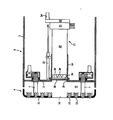
図1に示すように、本実施形態に係るトンネル掘削機は、筒体状のシールドフレーム1と、その内部を前後に仕切る隔壁2とを備えた掘削機本体3を有する。掘削機本体3の前部には、切羽を掘削する回転カッタ4が回転可能に取り付けられている。詳しくは、掘削機本体3の隔壁2には、回転リング5が軸受6を介して回転自在に装着されており、回転リング5には、周方向に所定間隔を隔てて設けられた中間ビーム7を介して回転カッタ4が取り付けられている。
【0017】
但し、回転カッタ4の掘削機本体3に対する取付方式は、かかる中間ビーム支持方式に限られるものではなく、上記中間ビーム7をより径方向外方に移動させた外周ビーム支持方式や、回転カッタ4にシールドフレーム1の前部(フード部)の内周面に入れ子状に嵌る嵌入筒体を取り付けた周辺支持方式であってもよい。要は、後述のように、回転カッタ4の中心部に、その前後を連通して開口部16を形成する都合上、センターシャフト支持方式でなければよい。
【0018】
回転リング5には、外歯ギヤ8が設けられている。外歯ギヤ8は、モータ9のピニオン10に噛合されている。この構成によれば、モータ9を駆動することで、回転リング5が回転し、中間ビーム7を介して回転カッタ4が回転する。回転カッタ4は、中間ビーム7に取り付けられたカッタヘッド11と、カッタヘッド11に取り付けられた複数のローラカッタ12およびティースビット13とからなる。
【0019】
各ローラカッタ12は、カッタヘッド11にその径方向に所定間隔を隔てて複数装着されており、カッタヘッド11の回転によって切羽面(岩盤)を転動し、切羽面に複数の同芯円の切り込みを形成する。また、各ティースビット13は、カッタヘッド11にその径方向に所定間隔を隔てて複数装着されており、カッタヘッド11の回転によって切羽面を摺動し、切り込みが形成された切羽面の岩盤を切削する。
【0020】
カッタヘッド11の周辺部(中心部以外)には、前後を連通させて土砂取込口14が複数形成されている。土砂取込口14は、ローラカッタ12およびティースビット13によって切削された切羽の土砂を、カッタヘッド11と隔壁2との間に区画されたカッタ室15に取り込むために設けられる。カッタ室15内に取り込まれた土砂は、図示しない土砂搬送装置(スクリューコンベヤ等)によって隔壁2の後方の坑内に搬送される。
【0021】
カッタヘッド11の中心部には、前後を連通させて円穴状の開口部16が形成されている。そして、開口部16の後方の隔壁2には、開口部16が対向する切羽を掘削するためのパーカッションドリル17が、回転カッタ4とは切り離して設けられている。パーカッションドリル17は、開口部16の後方の隔壁2に開けられた出没口18に繋げて取り付けられたガイド筒19内に、スライド自在に収容されている。
【0022】
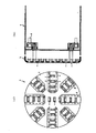
パーカッションドリル17は、図2にも示すように、円柱状の本体20と、本体20の後部に回転自在に被嵌されたスイベル21と、スイベル21に固設されたギヤケース22とを有する。そして、かかるパーカッションドリル17は、図1に示すように、本体20がガイド筒19内にスライド自在に収容され、スイベル21とガイド筒19との間に介設されたアクチュエータ(シリンダ23等)によってスライド移動される。
【0023】
図2に示すように、本体20の前部には、複数のビット24が軸方向に移動可能に装着されている。各ビット24は、スイベル21を介して本体20内に給排される高圧エアによって軸方向(前後方向)振動又は打撃される。すなわち、本体20内にはエアの供給通路25および排出通路26と振動又は打撃装置が形成されており、スイベル21の内周面にはこれら通路25、26にそれぞれ連通する環状のヘッダ室27、28が形成されている。
【0024】
そして、スイベル21には、各ヘッダ室27とヘッダ室28とに夫々連通されたエア供給ライン29と排出ライン30とが、取り付けられている。この構成によれば、供給ライン29に供給されたエアは、ヘッダ室27および供給通路25を通り、図示しない振動又は打撃機構により各ビット24を振動又は打撃させた後、排出通路26およびヘッダ室28を通って排出ライン30から排出される。なお、エアによりビット24を振動又は打撃させる機構自体は公知であるため説明を省略する。
【0025】
ギヤケース22の内部には、本体20に連結された被駆動ギヤ31と、被駆動ギヤ31に噛合するアイドルギヤ32と、アイドルギヤ32に噛合する駆動ギヤ(ピニオン33)とが収容されている。ピニオン33は、ギヤケース22に取り付けられたモータ34によって回転される。この構成によれば、モータ34を駆動することで、本体20がギヤケース22およびスイベル21に対して回転駆動される。
【0026】
本体20の内部には、ビット24によって掘削された土砂を取り込むための排土通路35が形成されている。排土通路35は、本体20の前面に入口を有し、本体の後部側面に出口を有する。出口は、スイベル21の内周面に環状に形成された排土用のヘッダ室36と連通している。そして、ヘッダ室36は、スイベル21に取り付けた排土ライン37と連通している。
【0027】
この構成によれば、モータ34を駆動しつつ供給ライン29にエアを供給することで、モータ34によって本体20が回転され同時にエアによって図示しない振動又は打撃機構により、各ビット24が振動又は打撃しながら回転する。これにより、回転カッタ4の中心部に開けられた開口部16の切羽が掘削され、その掘削土砂が排土通路35および排土ライン37を通って坑内に排出される。
【0028】
ここで、スイベル21とガイド筒19との間に介設されたシリンダ23は、各ビット24の先端位置を調節するのみならず、スイベル21およびギヤケース22の回り止めとしても機能する。また、本体20のガイド筒19に対するスライド位置は、上記シリンダ23によって調節された後、図示しないロック機構(シールドフレーム1側からスイベル21に係脱されるジャッキ等)によってその位置が固定される。
【0029】
図4に、上記パーカッションドリル17を最も後退させた様子を示す。このとき各ビット24の先端は、隔壁2に開けられた出没口18よりも後方に位置する。そして、出没口18は、隔壁2に設けられたシャッタ38によって閉じられる。シャッタ38は、図1および図2に示すように、通常時には出没口18を開放しており、図4のときのみスライドして出没口18を閉じる。
【0030】
これにより、シャッタ38より後方のガイド筒19内は、切羽の土圧等から切り離された状態となり、その内部に区画された収容室39内にて、先端のビット24を安全に交換することが可能となる。具体的には、ガイド筒19の側面に通常時には閉じられ図4のときのみ開かれる作業穴(図示せず)を設けておき、その作業穴を通じて先端のビット24を交換する。
【0031】
以上の構成からなる本実施形態の作用を述べる。
【0032】
図1に示すように、本実施形態に係るトンネル掘削機によれば、回転カッタ4の中心部が対向する切羽は、回転カッタ4から切り離して設けられたパーカッションドリル17によって掘削される。よって、図5に示す従来タイプのように中心部の切羽を回転カッタbを回転させて掘削することによって生じていた種々の問題は一切生じず、回転中心部の掘削性能が向上する。
【0033】
すなわち、図5に示すように、従来のトンネル掘削機は、回転駆動されるカッタヘッドcの掘削断面積全体にローラカッタeおよびティースビットfを装着し、カッタヘッドcの中心部においても、カッタヘッドcの回転によるローラカッタeおよびティースビットfの切羽面への円状の摺動によって切羽を掘削していたため、次のような問題が生じていた。
【0034】
先ず、カッタヘッドcの中心部に取り付けられたローラカッタeは、切羽面に対する摺動半径が小さいため、切羽面上を転動し難く、固着気味となり易い。このため、中心部のローラカッタeには、偏摩耗が発生し易い。また、摺動半径が小さいため、当該ローラカッタeの軸受に偏荷重が加わって軸受が破損する可能性もある。
【0035】
次に、カッタヘッドcの中心部では、外側部よりもローラカッタeの取付スペースが少ないため、ローラカッタeの取付間隔(カッタヘッドcの径方向に沿った取付間隔)を外側部と同等とすることが困難である上、土砂取込口gの開口スペースも確保し難い。このため、カッタヘッドcの中心部においては、ローラカッタeの偏摩耗・偏荷重の問題とも相俟って、掘削性能が低下し易い。
【0036】
このような種々の問題が生じていた図5に示す従来タイプに対し、図1に示す本実施形態は、問題となっていた回転カッタ4の中心部の切羽を、カッタヘッド11の回転によるローラカッタ12およびティースビット13の切羽面への円状の摺動によって掘削するのではなく、回転カッタ4とは切り離して設けたパーカッションドリル17によって叩いて掘削するので、上記種々の問題は一切生じない。
【0037】
つまり、回転カッタ4の中心部が対向する切羽(岩盤)は、上記パーカッションドリル17のビット24の振動又は打撃・回転によって破砕・掘削され、その以外の部分の切羽(岩盤)は、カッタヘッド11の回転に伴って各ローラカッタ12が転動することで同心円状に切り込まれ各ティースビット13によって切削される。これにより、回転中心部の掘削性能を従来タイプよりも向上できる。
【0038】
また、パーカッションドリル17には、当該ドリル17で掘削した土砂を掘進機本体内に移送する排土通路35が形成されているので、ビット24への土砂の付着が抑制され、長期に亘り安定した掘削性能を維持できる。すなわち、仮に排土通路35が無いとすると、パーカッションドリル17で掘削した土砂がビット24の部分に付着して掘削性能が低下する可能性があるが、これを回避できる。
【0039】
また、パーカッションドリル17が、隔壁2のガイド筒19に前後方向にスライド自在に設けられているので、パーカッションドリル17による回転カッタ4に対する先掘り又は後掘りが可能となる。また、図3に示すように、パーカッションドリル17のビット24の位置を回転カッタ4のローラカッタ12と面一として同時掘りとしてもよい。この場合、切羽が安定して掘削されることになる。
【0040】
そして、図3の状態からパーカッションドリル17を前進させた先掘りでは、回転カッタ4による掘削に先立って回転中心部の切羽がパーカッションドリル17で破砕されるため、回転カッタ4はその中心部が破砕された切羽を掘削することになり、回転カッタ4の掘削負担が小さくなる。よって、ローラカッタ12およびティースビット13(特に回転中心側のもの)の寿命が延びる。
【0041】
また、図3の状態からパーカッションドリル17を後退させた後掘り(図1)では、パーカッションドリル17は、回転カッタ4で掘削されることなく開口部16からカッタ室15内に柱状に侵入した切羽(岩盤)を破砕することになるため、掘削負担が小さくなる。よって、パーカッションドリル17のビット24の寿命が延びる。
【0042】
パーカッションドリル17のビット24のビット部が寿命となったなら、図4に示すように、パーカッションドリル17を後退させてガイド筒19の内部の収容室39に収容し、隔壁2の出没口18をシャッタ38で閉じる。これにより、シャッタ38より後方の収容室39内は、切羽の土圧等から切り離された状態となり、その収容室39内にて先端のビット24を安全に交換することが可能となる。
【0043】
なお、上記同時掘り、先掘り又は後掘りは、切羽(岩盤)の硬さや特性、各カッタ12、17の設定性能等に応じて、適宜切り替えられる。また、切羽の土質によっては、パーカッションドリル17の回転機構31、32、33、34を省略することもできる。また、本実施形態は、切羽が岩盤等の硬質地盤であって回転カッタ4にローラカッタ12を取り付けたタイプを説明したが、これに限定されるものではない。
【0044】
すなわち、本発明は、ローラカッタ12が装着されない回転カッタ4を備えた通常土質用のトンネル掘削機に適用してもよい。回転カッタ4を回転させてそれに装着したビットによって切羽を掘削する以上、回転中心部に取り付けられたビットの摺動半径は外側部のビットの摺動半径よりも小さくなり、中心部の掘削性能が外側部よりも低下することには変わりないからである。
【0045】
また、パーカッションドリル17の振動又は打撃機構は、図例のようにエアによって駆動されるものに限られず、油圧駆動としてもよい。
【0046】
【発明の効果】
以上説明したように本発明に係るトンネル掘削機によれば、回転カッタの回転中心部の掘削性能を向上させることができる。
【図面の簡単な説明】
【図1】本発明の一実施形態に係るトンネル掘削機の説明図であり、図1(a)は正面図、図1(b)は側断面図である。
【図2】上記トンネル掘削機に備えられたパーカッションドリルの説明図であり、図2(a)は正面図、図2(b)は側断面図である。
【図3】上記パーカッションドリルを前進させたトンネル掘削機の側断面図である。
【図4】上記パーカッションドリルを後退させたトンネル掘削機の側断面図である。
【図5】従来例を示すトンネル掘削機の説明図であり、図1(a)は正面図、図1(b)は側断面図である。
【符号の説明】
2 隔壁
3 掘削機本体
4 回転カッタ
12 ローラカッタ
16 開口部
17 パーカッションドリル
18 出没口
35 排土通路
38 シャッタ
39 収容室[0001]
TECHNICAL FIELD OF THE INVENTION
The present invention relates to a tunnel excavator provided with a rotary cutter, and more particularly, to a tunnel excavator having improved excavation performance at a center of rotation.
[0002]
[Prior art]
As shown in FIG. 5, a tunnel excavator such as a shield excavator or a tunnel boring machine generally includes a rotary cutter b for excavating a face at a front portion of an excavator body a. The rotary cutter b has a cutter head c rotatably mounted on the excavator body a, and the cutter head c is driven to rotate by a motor d.
[0003]
In a rock drilling tunnel excavator, a plurality of roller cutters e are mounted on a cutter head c. A plurality of these roller cutters e are mounted on the cutter head c at predetermined intervals in the radial direction, and roll the face (rock) by the rotation of the cutter head c. According to this configuration, by rotating the cutter head c by the motor d, a plurality of concentric notches are formed on the face by the rolling of each roller cutter e, and each tooth bit f provided on the cutter head c is formed. This cuts the rock face of the face.
[0004]
That is, in the conventional tunnel excavator, the roller cutter e and the teeth bit f are mounted on the entire excavation cross-sectional area of the cutter head c driven to rotate, and even in the center of the cutter head c, the roller cutter is rotated by the rotation of the cutter head c. The face was excavated by circular sliding of e and the teeth bit f on the face.
[0005]
[Problems to be solved by the invention]
However, since the roller cutter e attached to the center of the cutter head c has a small sliding radius (radius from the center of rotation) with respect to the face, the roller cutter e does not easily roll on the face and tends to stick. Therefore, uneven wear is likely to occur on the roller cutter e at the center of the cutter head c. Further, since the sliding radius is small, an eccentric load may be applied to the bearing of the roller cutter e, and the bearing may be damaged.
[0006]
Further, since the mounting space for the roller cutter e is smaller at the center of the cutter head c than at the outer portion, the mounting interval of the roller cutter e (the mounting interval along the radial direction of the cutter head c) is equal to that of the outer portion. In addition, it is difficult to secure the opening space of the sediment intake g. For this reason, in the center of the cutter head c, the excavation performance is apt to be reduced due to the problem of uneven wear and uneven load of the roller cutter e.
[0007]
SUMMARY OF THE INVENTION An object of the present invention, which has been made in view of the above circumstances, is to provide a tunnel excavator in which the excavation performance of a rotation center portion of a rotary cutter is improved.
[0008]
[Means for Solving the Problems]
In order to achieve the above object, a tunnel excavator according to the present invention has a rotary cutter provided for excavating a face at a front part of an excavator body, and is opened to communicate front and rear with a center part of the rotary cutter. The excavator body is provided with an opening and a percussion drill provided separately from the rotary cutter to excavate a face facing the opening.
[0009]
ADVANTAGE OF THE INVENTION According to this invention, the cutting face with which the center part of a rotary cutter opposes is hit and drilled by the percussion drill provided separately from the rotary cutter. Therefore, there is no problem at all caused by excavating the face facing the center of the rotating cutter by rotating the rotating cutter as in the conventional type, and the excavating performance of the rotating center is improved.
[0010]
Further, the percussion drill may be one that vibrates or hits in the front-rear direction and rotates about the front-rear axis. In this case, the face at the center of rotation is excavated by vibration or impact and rotation, so that the excavation performance is further improved.
[0011]
Further, the percussion drill may have an earth removal passage for transferring earth and sand excavated by the cutter into the body of the excavator. In this case, since the adhesion of the earth and sand to the percussion drill is suppressed, stable excavation performance can be maintained.
[0012]
Further, the percussion drill may be slidably provided in a partition wall in the excavator body in a front-rear direction. This makes it possible to pre-dig or rear-dig the rotary cutter with the percussion drill.
[0013]
Further, the partition may be provided with an accommodation chamber having a shutter for accommodating the retreated percussion drill and closing the opening thereof. In this case, the bit portion can be replaced by housing the percussion drill in the housing chamber and closing the shutter.
[0014]
Further, the rotating cutter may include a roller cutter that rolls on a face face by rotation of the rotating cutter. According to this configuration, the face at the center of the rotary cutter is crushed and excavated by the percussion drill, and the face at the other portion can be excavated by rolling of the roller cutter with rotation of the rotary cutter.
[0015]
BEST MODE FOR CARRYING OUT THE INVENTION
An embodiment of the present invention will be described with reference to the accompanying drawings.
[0016]
As shown in FIG. 1, the tunnel excavator according to the present embodiment includes an excavator main body 3 including a
[0017]
However, the method of attaching the rotary cutter 4 to the excavator body 3 is not limited to the intermediate beam supporting method, and the outer beam supporting method in which the intermediate beam 7 is moved more radially outward, and the rotating cutter 4 A peripheral support system may be used in which a fitting cylinder is fitted to the inner peripheral surface of the front part (hood part) of the
[0018]
An
[0019]
A plurality of
[0020]
A plurality of sediment inlets 14 are formed in the periphery (other than the center) of the
[0021]
A
[0022]
As shown in FIG. 2, the
[0023]
As shown in FIG. 2, a plurality of
[0024]
The
[0025]
Inside the
[0026]
Inside the
[0027]
According to this configuration, by supplying air to the
[0028]
Here, the
[0029]
FIG. 4 shows a state where the
[0030]
As a result, the inside of the
[0031]
The operation of the present embodiment having the above configuration will be described.
[0032]
As shown in FIG. 1, according to the tunnel excavator according to the present embodiment, the face facing the center of the rotary cutter 4 is excavated by a
[0033]
That is, as shown in FIG. 5, the conventional tunnel excavator mounts the roller cutter e and the teeth bit f on the entire excavation cross-sectional area of the rotary-driven cutter head c. Since the face was excavated by the circular sliding of the roller cutter e and the teeth bit f to the face face by the rotation of the head c, the following problem occurred.
[0034]
First, since the roller cutter e attached to the center of the cutter head c has a small sliding radius with respect to the face, the roller cutter e does not easily roll on the face, and tends to be stuck. For this reason, uneven wear tends to occur on the roller cutter e at the center. Further, since the sliding radius is small, an eccentric load may be applied to the bearing of the roller cutter e, and the bearing may be damaged.
[0035]
Next, since the mounting space for the roller cutter e is smaller at the center of the cutter head c than at the outer portion, the mounting interval of the roller cutter e (the mounting interval along the radial direction of the cutter head c) is equal to that of the outer portion. In addition, it is difficult to secure the opening space of the sediment intake g. For this reason, in the center of the cutter head c, the excavation performance is apt to be reduced due to the problem of uneven wear and uneven load of the roller cutter e.
[0036]
In contrast to the conventional type shown in FIG. 5 in which such various problems have occurred, the present embodiment shown in FIG. The
[0037]
That is, the face (rock) facing the center of the rotary cutter 4 is crushed and excavated by the vibration or impact / rotation of the
[0038]
In addition, since the
[0039]
In addition, since the
[0040]
Then, in the pre-digging in which the
[0041]
Further, in the back excavation in which the
[0042]
When the bit portion of the
[0043]
The simultaneous digging, the first digging, or the second digging is appropriately switched according to the hardness and characteristics of the face (rock), the setting performance of the
[0044]
That is, the present invention may be applied to a tunnel excavator for ordinary soil provided with the rotary cutter 4 to which the
[0045]
Further, the vibration or impact mechanism of the
[0046]
【The invention's effect】
As described above, according to the tunnel excavator according to the present invention, it is possible to improve the excavation performance of the rotation center of the rotary cutter.
[Brief description of the drawings]
FIG. 1 is an explanatory view of a tunnel excavator according to an embodiment of the present invention, FIG. 1 (a) is a front view, and FIG. 1 (b) is a side sectional view.
FIG. 2 is an explanatory view of a percussion drill provided in the tunnel excavator, wherein FIG. 2 (a) is a front view and FIG. 2 (b) is a side sectional view.
FIG. 3 is a side sectional view of a tunnel excavator in which the percussion drill is advanced.
FIG. 4 is a side sectional view of the tunnel excavator in which the percussion drill is retracted.
FIG. 5 is an explanatory view of a tunnel excavator showing a conventional example, where FIG. 1 (a) is a front view and FIG. 1 (b) is a side sectional view.
[Explanation of symbols]
2 Partition wall 3 Excavator main body 4
Claims (6)
Priority Applications (1)
| Application Number | Priority Date | Filing Date | Title |
|---|---|---|---|
| JP2002176970A JP2004019302A (en) | 2002-06-18 | 2002-06-18 | Tunnel boring machine |
Applications Claiming Priority (1)
| Application Number | Priority Date | Filing Date | Title |
|---|---|---|---|
| JP2002176970A JP2004019302A (en) | 2002-06-18 | 2002-06-18 | Tunnel boring machine |
Publications (1)
| Publication Number | Publication Date |
|---|---|
| JP2004019302A true JP2004019302A (en) | 2004-01-22 |
Family
ID=31175127
Family Applications (1)
| Application Number | Title | Priority Date | Filing Date |
|---|---|---|---|
| JP2002176970A Pending JP2004019302A (en) | 2002-06-18 | 2002-06-18 | Tunnel boring machine |
Country Status (1)
| Country | Link |
|---|---|
| JP (1) | JP2004019302A (en) |
Cited By (9)
| Publication number | Priority date | Publication date | Assignee | Title |
|---|---|---|---|---|
| WO2010093775A3 (en) * | 2009-02-11 | 2010-12-02 | Vermeer Manufacturing Company | Tunneling apparatus |
| WO2011115610A1 (en) * | 2010-03-15 | 2011-09-22 | Vermeer Manufacturing Company | Drilling apparatus with shutter |
| KR101074201B1 (en) * | 2004-02-16 | 2011-10-14 | 주식회사 케이티 | Tunneling Machine Installed Roller Cutter for Easy Turning Function |
| CN102287200A (en) * | 2011-07-15 | 2011-12-21 | 天津大学 | Shield machine cutter head with post center cutter |
| CN103590837A (en) * | 2013-11-20 | 2014-02-19 | 天津大学 | Eccentric cutter type shield machine cutterhead |
| CN104047608A (en) * | 2014-05-05 | 2014-09-17 | 湖北博创机械制造有限责任公司 | Heading device for hard rock rapid heading machine |
| CN109184712A (en) * | 2018-09-06 | 2019-01-11 | 西安科技大学 | A kind of shield machine impact hobboing cutter certainly and the method using its impact grinding scar |
| CN109209426A (en) * | 2018-11-08 | 2019-01-15 | 南京工业职业技术学院 | A kind of compound broken rock cutter of impact rolling cut |
| CN113605911A (en) * | 2021-08-30 | 2021-11-05 | 中国铁建重工集团股份有限公司 | Cutter head assembly, tunnel driving equipment and tunnel driving construction method |
-
2002
- 2002-06-18 JP JP2002176970A patent/JP2004019302A/en active Pending
Cited By (12)
| Publication number | Priority date | Publication date | Assignee | Title |
|---|---|---|---|---|
| KR101074201B1 (en) * | 2004-02-16 | 2011-10-14 | 주식회사 케이티 | Tunneling Machine Installed Roller Cutter for Easy Turning Function |
| WO2010093775A3 (en) * | 2009-02-11 | 2010-12-02 | Vermeer Manufacturing Company | Tunneling apparatus |
| WO2011115610A1 (en) * | 2010-03-15 | 2011-09-22 | Vermeer Manufacturing Company | Drilling apparatus with shutter |
| CN102892975A (en) * | 2010-03-15 | 2013-01-23 | 维米尔制造公司 | Drilling apparatus with shutter |
| CN102287200A (en) * | 2011-07-15 | 2011-12-21 | 天津大学 | Shield machine cutter head with post center cutter |
| CN103590837A (en) * | 2013-11-20 | 2014-02-19 | 天津大学 | Eccentric cutter type shield machine cutterhead |
| CN104047608A (en) * | 2014-05-05 | 2014-09-17 | 湖北博创机械制造有限责任公司 | Heading device for hard rock rapid heading machine |
| CN109184712A (en) * | 2018-09-06 | 2019-01-11 | 西安科技大学 | A kind of shield machine impact hobboing cutter certainly and the method using its impact grinding scar |
| CN109184712B (en) * | 2018-09-06 | 2024-03-01 | 西安科技大学 | Self-impact hob for shield machine and method for impact breaking rock surface by using self-impact hob |
| CN109209426A (en) * | 2018-11-08 | 2019-01-15 | 南京工业职业技术学院 | A kind of compound broken rock cutter of impact rolling cut |
| CN113605911A (en) * | 2021-08-30 | 2021-11-05 | 中国铁建重工集团股份有限公司 | Cutter head assembly, tunnel driving equipment and tunnel driving construction method |
| CN113605911B (en) * | 2021-08-30 | 2024-02-02 | 中国铁建重工集团股份有限公司 | Cutter head assembly, tunneling equipment and tunneling construction method |
Similar Documents
| Publication | Publication Date | Title |
|---|---|---|
| WO2011092964A1 (en) | Bit-replacing device for excavator | |
| JP2004019302A (en) | Tunnel boring machine | |
| JP2002276291A (en) | Cutter head for shield machine | |
| JPWO2013084543A1 (en) | Tunnel drilling equipment | |
| JP2017141590A (en) | Tunnel excavator | |
| JP4004339B2 (en) | Tunnel excavator | |
| JP2022048035A (en) | Tunnel excavator, excavation tool exchange device, and excavation tool exchange method | |
| JP2004251042A (en) | Tunnel excavator | |
| JP3832005B2 (en) | Shield machine | |
| JP4433601B2 (en) | Cutter bit exchange structure | |
| JP4122281B2 (en) | Shield excavator cutter plate | |
| JP3396446B2 (en) | Tunnel excavator | |
| JP2910633B2 (en) | Method for reducing wear of cutter bit and structure for mounting cutter bit | |
| JP2004068350A (en) | Shield machine and exchanging method for cutter bit | |
| JP4173995B2 (en) | Cutter moving device and method, cutter exchanging method and tunnel excavator | |
| JP3634625B2 (en) | Cutter device and tunnel excavator | |
| JP3403384B2 (en) | Underground excavator | |
| JPH0714476Y2 (en) | Horizontal hole drilling equipment | |
| JP3491681B2 (en) | Multi air hammer device | |
| JP2002227590A (en) | Cutter washing device for tunnel boring machine | |
| JP4197921B2 (en) | Cutter device and tunnel excavator provided with the same | |
| JP2002276290A (en) | Cutter head for shield machine | |
| JP3776815B2 (en) | Shield machine | |
| JP4162444B2 (en) | Shield machine | |
| JP3002363B2 (en) | Excavation equipment for shield machine |
Legal Events
| Date | Code | Title | Description |
|---|---|---|---|
| A621 | Written request for application examination |
Free format text: JAPANESE INTERMEDIATE CODE: A621 Effective date: 20050512 |
|
| A977 | Report on retrieval |
Free format text: JAPANESE INTERMEDIATE CODE: A971007 Effective date: 20070412 |
|
| A131 | Notification of reasons for refusal |
Effective date: 20070424 Free format text: JAPANESE INTERMEDIATE CODE: A131 |
|
| A02 | Decision of refusal |
Free format text: JAPANESE INTERMEDIATE CODE: A02 Effective date: 20070821 |