【0001】
【発明の属する技術分野】
本発明は、車両用電動スライドドアの安全装置に関し、特に、電動スライドドアによる挟込み発生を高レスポンスに検知することができ、且つ安価な電動スライドドアの安全装置に関する。
【0002】
【従来の技術】
近年においては、電送スライドドアシステムの配設された車両が市販されている。ここで、電送スライドドアシステムを車両に配設するに当たっては、スライドドアと車両本体(ボディ)との間に腕や物等が挟込まれてしまうことを防止するための安全装置を設ける必要がある。
【0003】
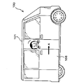
図6は、従来技術の安全装置を搭載した車両100の側面図であるが、この図6に示すように、従来の車両100には、スライドドア106の挟込検知手段として、スライドドア106端部の弾性体(図示せず)内部に設けられた感圧センサ91が用いられていた。この感圧センサ91は、スライドドア106が人物などを挟み込んで弾性体を圧縮した場合に、内部の電極同士が接触し、電気信号を出力する。これにより、スライドドア106による挟込みの発生を検知することができるのである。かかる電気信号はECU(Electric Control Unit)12へ送信され(▲4▼)、ECU12よりモータ102のドライバ部に対して回転停止信号が送信されることにより、図8に示すように、スライドドア106の閉塞時(矢印A方向へのスライド(摺動)時)における挟込みが防止される。感圧センサ91を車両本体101側に設けた場合にも同様であるので、その説明を省略する。
【0004】
【発明が解決しようとする課題】
しかしながら、挟込検出手段として感圧センサ91を用いると、感圧センサ91の部品単価が高額であるが故に、結果として、安全装置全体のコストが嵩んでしまうという問題点があった。
【0005】
そこで、この問題点を解決する一方式として、モータ102の負荷電流(Im(以下、便宜上、「モータ電流」と称する))を計測し、図7に示すように、このモータ電流(Im)が挟込電流しきい値(Imt)に達した場合に、挟込みとして検知する方式がある。
【0006】
しかしながら、スライドドア106により挟み込まれた物体が例えばクッション等の柔らかいものである場合には、モータ電流(Im)が挟込電流しきい値(Imt)に達するまでに時間がかかる(Imの傾きが小さい)、即ち、挟込み検知の応答性が悪いという問題点があった。
【0007】
以上の問題点を鑑みて案出されたのが本発明であって、本発明は、電動スライドドアによる挟込み発生を高レスポンスに検知することができ、且つ安価な電動スライドドアの安全装置に関する。
【0008】
【課題を解決するための手段】
この目的を達成するために請求項1記載の車両用電動スライドドアの安全装置は、車両用の電動スライドドアの開閉に伴う挟込みを検知する挟込検知手段と、該挟込検知手段の検知に応じて前記電動スライドドアの開閉の停止のための開閉停止手段とを備えており、前記挟込検知手段は、前記電動スライドドアの開閉のための車両本体側に固定されるモータの負荷電流を検出する電流検出手段と、前記電動スライドドアの位置を前記モータの回転角に対応させて検出する位置検出手段と、前記電流検出手段及び位置検出手段の両検出手段の検出値に応じて挟込検知信号を出力する信号出力手段とを備えている。
【0009】
請求項2記載の車両用電動スライドドアの安全装置は、請求項1記載の車両用電動スライドドアの安全装置において、信号出力手段は、電流検出手段の検出値が第1のしきい値よりも大きくなった場合、又は位置検出手段の検出値の単位時間当たりの変位量が第2のしきい値よりも小さい場合の少なくとも何れかの場合に、挟込検知信号を出力するようにされている。
【0010】
請求項3記載の車両用電動スライドドアの安全装置は、請求項1又は2に記載の車両用電動スライドドアの安全装置において、位置検出手段は、モータの回転角を減速機出力軸の回転角として検出するポテンショメータ型の回転角検出手段である。
【0011】
【発明の実施の形態】
次ぎに、添付図面を参照して、本発明の好ましい実施例について説明する。勿論、下記実施例は、本発明の好ましい実施例を説明するに過ぎず、本発明の技術的範囲は、下記実施例に何ら限定されるものではない。
【0012】
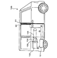
図1は、本発明の一実施例である車両用電動スライドドアの安全装置(以下、便宜上、単に「安全装置」と称する)1を車両100に搭載した状態における概略図である。
【0013】
まず、図1を参照して、車両用電動スライドドアシステムの概略について説明する。車両100の乗車者により所定のスイッチ操作が為されると、ECU12よりモータ102のドライバ部(図示せず)に対して信号が送信され、車両本体101側に搭載されたモータ102が回転する。このモータ102の回転(駆動力)は、該モータ102に連設される減速機103、巻取ドラム104及びワイヤー(巻取ドラム104に一端の結着される一方、他端が車両本体101側面に配設されるスライドドア106に結合されている伝達手段の一種。勿論、ワイヤー以外のチェーン、ベルト等であっても良い。)105を介して、スライドドア106へ伝達される。そして、このようにモータ102の回転がスライドドア106へ伝達されることにより、スライドドア106は、矢印A方向又は矢印B方向へ摺動(スライド)される、即ち、開放(矢印B方向)又は閉塞(矢印A方向)させられるのである。ここで、モータ102の回転角とスライドドア106の開閉位置とは、対応しており、このスライドドア106の開閉速度は、モータ電流(Im)に比例する。
【0014】
安全装置1は、このスライドドア106と車両本体101との間の挟込みを防止するためのものであり、ポテンショメータ11と、ECU12とによって構成されている。
【0015】
ポテンショメータ11は、スライドドア106の位置検出のための一方式(一手段)であり、減速機103を介したモータ102の回転角(量)を測定するために、減速機103の回転軸(図示せず)に対して同軸状に取付け固定されている。ポテンショメータ11により、モータ102の回転角(本実施例においては、モータ102の回転角を減速機103の回転角として検出)に応じた大きさの電圧が出力され、このポテンショメータ11により出力される電圧(以下、便宜上、「ポテンショ出力電圧」と称する)(Vp)。ポテンショ出力電圧(Vp)は、後述するECU12によりデジタル変換されて、スライドドア106の開閉制御に使用される。なお、勿論、減速機103を介することなくモータ102の回転角を直接に測定するようにしてもよいが、減速機103を介した方がポテンショメータ11の大きさを小さくすることができ、又は制御の煩雑さを解消することができる。
【0016】
ECU12は、車両100を走行させるために必要な制御や、カーナビ等の種々のアクセサリーを稼働させるために必要な制御等を行うためのものであり、図示しない、演算装置(CPU等)や、記憶装置(RAM、ROM等)、変換器(A/D変換器、D/A変換器)等によって構成されている。
【0017】
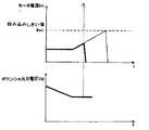
図2を参照して、ECU12により実行される具体的な制御の一例を示す。図2に示すように、ECU12は、ポテンショ出力電圧(Vp)およびモータ電流(Im)を所定時間毎(例えば、1ms毎)に検知(▲1▼,▲2▼)するとともに、ポテンショ出力電圧(Vp)の単位(1sに限られず、例えば、2msであってもよい。)時間当たりの変位量を演算する(具体例としては、ポテンショ出力電圧(Vp)を時間(t)で微分する演算をする)。そして、モータ電流(Im)の大きさが第1のしきい値(挟込電流しきい値)以上となった場合は勿論のこと、モータ電流(Im)の大きさが第1のしきい値以上でなくても、ポテンショ出力電圧(Vp)の単位時間当たりの変位量が第2しきい値(電圧変位しきい値)以下である場合、即ち、図2におけるポテンショ出力電圧(Vp)の傾きが正常値よりも小さくなった場合(図2中におけるXの時点)には、スライドドア106により挟込みが発生したと検知(判定)し、モータ102に対して回転の停止信号を送信するのである(▲3▼)。勿論、回転停止信号の送信後、更に、回転反転信号を送信するようにしても良い。この回転反転信号の送信に伴い、スライドドア106の停止後に、スライドドア106を所定量分、停止前と逆向きにスライドするようにされている。
【0018】
ここで、モータ負荷電流(Imt)は、正常時においても、種々の要因により一定値とならず、若干の変動する。このため、挟込電流しきい値(Imt)をシビアに設定してしまうと(低い値に設定すると)、誤動作を生ずる恐れがある。このため、挟込電流しきい値(Imt)を大きめの値に設定する必要が生じる。しかしながら、スライドドア106により挟み込まれた物体が例えばクッション等の柔らかいものである場合には、負荷電流(Im)が挟込電流しきい値Imtに達するまでに時間がかかる(Imの傾きが小さい)、即ち、挟込み検知の応答速度が遅くなる。このため、本発明においては、挟込み検知の更なる応答速度の向上(レスポンス性(応答性)の向上)のために、モータ電流(Imt)に基づいてのみ挟込みを検知するのではなく、ポテンショ出力電圧変位(dVp/dt)にも基づいて挟込みを検知する方式とされている。これは、モータ102の回転角の変位が少ない場合には、スライドドア106が予定通り(制御通り)スライドしていることを意味することに起因している。
【0019】
上記のように、本発明は、モータ電流(Imt)に基づいてのみ挟込みを検知するのではなく、ポテンショ出力電圧変位(dVp/dt)にも基づいて挟込みを検知する方式とされている。従って、「従来の技術」及び「発明が解決しようとする課題」の欄で説明したような、感圧センサ91,92を用いなくても、高レスポンスな挟込み検出をすることができるとともに、製造コストを安価とすることができるのである。
【0020】
また、「従来の技術」の欄等において説明した、感圧センサ91は固定体である車両本体101側に設けられるものではなく、移動体であるスライドドア106側に設けられる方が好ましい。なぜなら、挟込みの検知に加え、一の感圧センサ91により、スライドドア106の衝突検知をも可能であるからである。この場合、感圧センサ91より延出するケーブル(図示せず)を車両本体101側に引き込まなければならないが、スライドドア106が移動体であるため、その移動量分を考慮して配線したり、ケーブルがスライドドア106の開閉動作と干渉しないように配線しなければならず、非常に煩雑な配線作業を要するという問題点があった。
【0021】
更には、挟込の検出手段として感圧センサを用いる場合、図6に示すように、スライドドア106の端部のみならず、スライドドア106に配設される車窓106aの窓枠にも、同様に感圧センサ92を設ける方が好ましい。これにより、スライドドア106の車窓106aより顔や手などが出されている場合に、スライドドア106が開放した(矢印B方向へスライドする)ときにおいても、感圧センサ92よりECU12に対して信号が送信され(▲5▼)、挟込みの発生が検知される。即ち、図9に示すように、顔や手が車窓106aの窓枠と車両本体との間に挟まれてしまうことをも防止することができるのである。しかしながら、この場合においても、スライドドア106端部に感圧センサ91を設けたときと同じ問題点を有している。勿論、スライドドア106に設けられた車窓106aが開閉しない場合や、かかる車窓106aが閉塞している状態でのみスライドドア106の開閉ができない場合には、要しない。
【0022】
しかしながら、本発明によれば、モータ102及びそのモータ102に連設される減速機103に取付固定されるポテンショメータ11、並びに、ECU12は、何れも、車両本体101側に配設されている。言い換えれば、本安全装置1の構成要素は、何れも、スライドドア106側に設けられている。これが故に、本発明によれば、煩雑な配線作業を解消することができるのである。更には、スライドドア106の挟込のみならず、衝突をも検知することが可能である。
【0023】
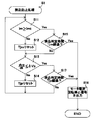
次ぎに、図4を参照して、上記のように構成された安全装置1の動作について、具体的には、挟込防止処理(S1)について説明する。まず、モータ電流(Im)が挟込電流しきい値(Imt)以上であるか否かを判断する(S11)。モータ電流(Im)が挟込電流しきい値Imt以上である場合には(S11:Yes)、その異常状態の継続が電流用挟込判定時間(Tjm)を経過したか否かを判断する(S15)。このように電流用挟込判定時間(Tjm)を設け、このTjmを適宜の値に設定することにより、誤動作を防止することができるのである。電流用挟込判定時間(Tjm)を経過していない場合には(S15:No)、次にポテンショ出力電圧変位(dVp/dt)が電圧変位しきい値(ΔVp)以下であるか否かを判断する(S13)。
【0024】
一方、S11の処理においてモータ負荷電流(Im)が挟込電流しきい値(Imt)より小さい場合には(S11:No)、モータ負荷電流(Im)がもともと正常であったか、或いは正常に戻ったのであるから、挟込判定時間Tjmをリセットし(S12)、次にポテンショ出力電圧変位(dVp/dt)が電圧変位しきい値(ΔVp)以下であるか否かを判断する(S13)。
【0025】
ポテンショ出力電圧変位(dVp/dt)が電圧変位しきい値(ΔVp)以下である場合には(S13:Yes)、その異常状態の継続が電圧変位用挟込判定時間(Tjp)を経過したか否かを判断し(S17)、電圧変位用挟込判定時間(Tjp)を経過していなければ(S17:No)、処理をS11へ移行して、再度、モータ電流(Im)が挟込電流しきい値(Imt)以上であるか否かを判断する(S11)。
【0026】
一方、S13の処理においてポテンショ出力電圧変位(dVp/dt)が電圧変位しきい値(ΔVp)より大きい場合には(S13:No)、ポテンショ出力電圧変位(dVp/dt)がもともと正常であったか、或いは正常に戻ったのであるから、電圧変位用挟込判定時間(Tjp)をリセット(S14)し、処理をS11へ移行する。
【0027】
ここで、S15の処理又はS17の処理においてモータ負荷電流(Im)又はポテンショ出力電圧変位(dVp/dt)の少なくとも何れか一方の異常状態の継続が挟込判定時間(Tjm,Tjp)を経過した場合には(S15:Yes,S17:Yes)、スライドドア106による挟込みが発生していると検知して、モータ102のドライブ部に対してモータ電流回転停止信号を出力し(S16)、挟込防止処理(S1)を終了する。
【0028】
次に、図5を参照して、安全装置1において実施される第2の好適な挟込防止処理について説明する。図5は、第2挟込防止処理(S2)を示すフローチャートである。この第2挟込防止処理(S2)は、挟込防止処理(S1)に対し、スライドドア106の始動時、全開直前時、全閉直前時など、意図的にスピードを遅くする制御の最中においては電圧変位しきい値を変化させる点において相違する。以下、挟込防止処理(S1)と同一の部分には、同一の符号を付してその説明を省略し、異なる部分のみを説明する。
【0029】
S11の処理においてモータ電流(Im)が挟込電流しきい値(Imt)より小さい場合(S11:No)、又は、S15の処理において異常状態の継続が電流用挟込判定時間(Tjm)を経過していない場合には、S21の処理に移行されるが、このS21の処理においては、ポテンショ出力電圧(Vp)が高側出力電圧しきい値(Vph)以上であるか否か、又は、低側出力電圧しきい値(Vpl)以下であるか否かが判断される(S21)。ポテンショ出力電圧(Vp)が低側出力電圧しきい値(Vpl)と高側出力電圧しきい値(Vph)との間にある場合には(S21:Yes)、通常制御時であるから、処理をS13へ移行するとともに、挟込防止処理(S1)と同様の処理を実行する。
【0030】
S21の処理においてポテンショ出力電圧(Vp)が低側出力電圧しきい値(Vpl)と高側出力電圧しきい値(Vph)との間にない場合には(S21:No)、低速制御時であるから、ポテンショ出力電圧変位(dVp/dt)が第2電圧変位しきい値(ΔVp2)以下であるか否かを判断する(S22)。この第2電圧変位しきい値(ΔVp2)は、電圧変位しきい値(ΔVp)よりも小さい適宜の値である。ポテンショ出力電圧変位(dVp/dt)が第2電圧変位しきい値(ΔVp2)以下である場合には(S22:Yes)、異常状態の継続が第2電圧変位用挟込判定時間(Tjp2)を経過したか否かを判断し(S23)、経過していなければ(S23:No)、処理をS11へ移行する。同様に、ポテンショ出力電圧変位(dVp/dt)が第2電圧変位しきい値(ΔVp2)より大きい場合には(S22:Yes)、Tjp2をリセットして(S24)、処理をS11へ移行する。
【0031】
一方、S23の処理においてポテンショ出力電圧変位(dVp/dt)の異常状態の継続がTjp2を経過した場合には(S23:Yes)、低速制御時であるにも拘わらず、更に、スライドドア106の移動速度が遅いであるから、モータ回転停止信号を出力して(S16)、第2挟込防止処理を終了する。
【0032】
このように、スライドドア106の始動時、全開直前時、全閉直前時など、意図的にスピード(開閉速度)を遅くする制御の最中においては電圧変位しきい値を変化させることにより(通常時とは別のしきい値を用いることにより)、意図的にスピードを遅くしている場合に、誤動作してしまうことを防止することができる。なお、特別時のしきい値は、一つに限られず、特別なケース毎に夫々のしきい値を設けてもよい。
【0033】
以上、実施例に基づき本発明を説明したが、上記の実施例は、本発明の趣旨を逸脱しない範囲内で種々の改良変形が可能であることは容易に推察することができるものであり、本発明の技術的範囲には、この種々の改良変形をも含まれる。
【0034】
例えば、本実施例によれば、挟込みを検知した場合には、ECU12によりモータ102のドライバ部に対して回転停止信号が送信されるようにされている。そして、この回転停止信号の送信によりスライドドア106の開閉動作が停止されるのであるが、スライドドア106の開閉停止方式は、モータ102のドライバ部に対する回転停止信号の送信に限られるものではなく、例えば、減速機103と巻取ドラム104との間にクラッチ機構が設けられている場合には、このクラッチ機構により減速機103と巻取ドラム104との接続を切断するようにしても良い。この場合、スライドドア106自体を直接に停止させる方式(例えば、モータ102の停止、ブレーキパッドのスライドドア106への当接など)が好ましい。
【0035】
また、本実施例によれば、スライドドア106の位置検出方式として、ポテンショメータ11による減速機103を介したモータ102の回転角(量)を検出する方式が用いられているが、スライドドア106の位置検出方式は、ポテンショメータ11によるモータ102の回転角の検出方式に限られず、他の手段(機構)によりモータ102の回転角を検出する方式としても良いし、光電スイッチ等を使用してスライドドア106の移動量を直接に検出する方式としても良い。
【0036】
ここで、上記実施例において、S1の処理(即ち、S11からS17までの各処理)、並びにS2の処理(S11からS13まで及びS21からS24までの各処理)は、請求項に記載の信号出力手段により実行される処理に該当する。
【0037】
なお、特許請求の範囲に記載された用語の解釈について疑義が生じないように念のために説明すれば、「請求項2記載の信号出力手段」には、電流検出手段の検出値が第1のしきい値よりも大きくなった場合にのみ挟込検知信号を出力するものが含まれることは勿論のこと、電流検出手段の検出値が第1のしきい値よりも大きくなった場合に挟込検知信号を出力するのであれば、電流検出手段の検出値が第1のしきい値と同一値であるときにも挟込検知信号を出力するもの、をも包含する。位置検出手段についても電流検出手段と同様であるので詳細な説明は省略する。
【0038】
【発明の効果】
請求項1記載の車両用電動スライドドアの安全装置によれば、信号出力手段により、モータの負荷電流値に応じた電流検出手段の検出値、及びモータの回転角に対応するスライドドアの開閉位置に応じた位置検出手段の検出値の両検出値の比較結果に基づいて、挟込検知信号が出力され、開閉停止手段により、挟込検知信号の出力に応じて電動スライドドアの開閉が停止される。従って、高価な感圧センサを用いなくても、挟込みを検知することができ、ひいては、製造コストを低減することができるという効果がある。
【0039】
請求項2記載の車両用電動スライドドアの安全装置によれば、請求項1記載の車両用電動スライドドアの安全装置の奏する効果に加え、更に、電流検出手段の検出値の単位時間当たりの変位量が第1のしきい値より大きく、位置検出手段の検出値の単位時間当たりの変位量が第2のしきい値よりも小さい場合に、信号出力手段による挟込検知信号の出力が為されるので、挟み込まれた物が柔らかい場合にも、挟込み検知のレスポンス性が損なわれてしまうことを防止することができるという効果がある。
【0040】
請求項3記載の車両用電動スライドドアの安全装置によれば、請求項1又は2に記載の車両用電動スライドドアの安全装置の奏する効果に加え、更に、電動スライドドアの位置を検出する位置検出手段がモータの回転角を減速機出力軸の回転角として検出するポテンショメータ型の回転角検出手段により構成されているので、スライドドアの位置をドア側スイッチ等により直接的に検知する方式に比べて、簡素な機構で電動スライドドアの位置を検出することができると共に、煩雑な配線作業を解消することができるという効果がある。
【図面の簡単な説明】
【図1】本発明の一実施例である車両用電動スライドドアの安全装置を搭載した車両の側面図である。
【図2】挟込み発生時におけるモータの負荷電流およびポテンショメータの出力電圧の変移を示す図である。
【図3】対比例の車両用電動スライドドアの安全装置を搭載した車両の側面図である。
【図4】本安全装置より実行される挟込防止処理を示すフローチャートである。
【図5】本安全装置より実行される第2挟込防止処理を示すフローチャートである。
【図6】従来技術の車両用電動スライドドアの安全装置を搭載する車両の側面図である。
【図7】別の従来技術の車両用電動スライドドアの安全装置における挟込検知のタイミングを説明する図である。
【図8】仮に電動スライドドアにより人が挟まれた状態を示した図である。
【図9】仮に電動スライドドアにより人が挟まれた状態を示した図である。
【符号の説明】
1 車両用電動スライドドアの安全装置(安全装置)
11 ポテンショメータ(位置検出手段および回転角検出手段の一手段の構成部)
12 ECU(位置検出手段および回転角検出手段の一手段の構成部、並びに、信号出力手段および電流検出手段)
100 車両
101 車両本体
102 モータ
103 減速機
104 巻取ドラム
105 ワイヤー
106 スライドドア[0001]
TECHNICAL FIELD OF THE INVENTION
The present invention relates to a safety device for an electric sliding door for a vehicle, and more particularly to an inexpensive safety device for an electric sliding door which can detect occurrence of pinching by the electric sliding door with high response.
[0002]
[Prior art]
In recent years, vehicles equipped with an electric sliding door system are commercially available. Here, in disposing the transmission slide door system in a vehicle, it is necessary to provide a safety device for preventing an arm or an object from being caught between the slide door and the vehicle body (body). is there.
[0003]
FIG. 6 is a side view of the vehicle 100 equipped with the safety device of the related art. As shown in FIG. The pressure-sensitive sensor 91 provided inside the elastic member (not shown) is used. When the sliding door 106 sandwiches a person or the like and compresses the elastic body, the pressure-sensitive sensor 91 contacts the internal electrodes and outputs an electric signal. As a result, the occurrence of pinching by the slide door 106 can be detected. The electric signal is transmitted to an ECU (Electric Control Unit) 12 ([4]), and a rotation stop signal is transmitted from the ECU 12 to the driver of the motor 102, as shown in FIG. At the time of closing (when sliding (sliding) in the direction of arrow A) is prevented. The same applies to the case where the pressure-sensitive sensor 91 is provided on the vehicle main body 101 side, and the description thereof is omitted.
[0004]
[Problems to be solved by the invention]
However, when the pressure-sensitive sensor 91 is used as the pinch detecting means, the unit price of the pressure-sensitive sensor 91 is high, and as a result, there is a problem that the cost of the entire safety device increases.
[0005]
Therefore, as one method for solving this problem, a load current (Im (hereinafter, referred to as “motor current” for convenience)) of the motor 102 is measured, and as shown in FIG. There is a method of detecting a pinch when the pinch current threshold (Imt) is reached.
[0006]
However, when the object sandwiched by the slide door 106 is a soft material such as a cushion, it takes time for the motor current (Im) to reach the sandwich current threshold value (Imt) (the slope of Im becomes small). Small), that is, there is a problem that the response of the pinch detection is poor.
[0007]
The present invention has been devised in view of the above problems, and the present invention relates to an inexpensive electric slide door safety device capable of detecting the occurrence of entrapment by the electric slide door with high response. .
[0008]
[Means for Solving the Problems]
In order to achieve this object, a safety device for an electric sliding door for a vehicle according to claim 1 comprises a detecting means for detecting an entrapment caused by opening and closing of the electric sliding door for a vehicle, and detecting the entrapment detecting means. Opening / closing stop means for stopping the opening / closing of the electric slide door, and the pinch detection means comprises a load current of a motor fixed to a vehicle body for opening / closing the electric slide door. Current detecting means, a position detecting means for detecting the position of the electric sliding door in correspondence with the rotation angle of the motor, and a position detecting means for detecting the position of the electric sliding door in accordance with the detected values of the current detecting means and the position detecting means. Signal output means for outputting an intrusion detection signal.
[0009]
According to a second aspect of the present invention, in the safety device for an electric vehicle sliding door according to the first aspect, the signal output means is configured such that a detection value of the current detection means is smaller than a first threshold value. The pinch detection signal is output when at least one of the case where the value has become large or the amount of displacement of the detection value of the position detection means per unit time is smaller than the second threshold value. .
[0010]
The safety device for a vehicle electric sliding door according to claim 3 is the safety device for a vehicle electric sliding door according to claim 1 or 2, wherein the position detecting means determines the rotation angle of the motor as the rotation angle of the output shaft of the speed reducer. This is a potentiometer-type rotation angle detecting means for detecting the rotation angle.
[0011]
BEST MODE FOR CARRYING OUT THE INVENTION
Next, preferred embodiments of the present invention will be described with reference to the accompanying drawings. Needless to say, the following embodiments merely describe preferred embodiments of the present invention, and the technical scope of the present invention is not limited to the following embodiments.
[0012]
FIG. 1 is a schematic diagram showing a state in which a safety device (hereinafter simply referred to as “safety device”) 1 for an electric sliding door for a vehicle according to an embodiment of the present invention is mounted on a vehicle 100.
[0013]
First, an outline of an electric sliding door system for a vehicle will be described with reference to FIG. When a predetermined switch operation is performed by a rider of the vehicle 100, a signal is transmitted from the ECU 12 to a driver unit (not shown) of the motor 102, and the motor 102 mounted on the vehicle body 101 rotates. The rotation (driving force) of the motor 102 is controlled by a reduction gear 103, a winding drum 104, and a wire (one end is connected to the winding drum 104 while the other end is connected to the side of the vehicle body 101). Is transmitted to the slide door 106 through a type of transmission means coupled to the slide door 106 provided in the slide door 106. Of course, a chain, a belt, or the like other than a wire may be used. When the rotation of the motor 102 is transmitted to the slide door 106 in this manner, the slide door 106 is slid (slid) in the arrow A direction or the arrow B direction, that is, opened (the arrow B direction) or It is closed (in the direction of arrow A). Here, the rotation angle of the motor 102 corresponds to the open / close position of the slide door 106, and the open / close speed of the slide door 106 is proportional to the motor current (Im).
[0014]
The safety device 1 is for preventing the sliding door 106 from being caught between the vehicle body 101 and includes a potentiometer 11 and an ECU 12.
[0015]
The potentiometer 11 is a method (one means) for detecting the position of the slide door 106, and measures a rotation axis (amount) of the speed reducer 103 in order to measure a rotation angle (amount) of the motor 102 via the speed reducer 103. (Not shown). The potentiometer 11 outputs a voltage having a magnitude corresponding to the rotation angle of the motor 102 (in this embodiment, the rotation angle of the motor 102 is detected as the rotation angle of the speed reducer 103), and the voltage output by the potentiometer 11 (Hereinafter, for convenience, it will be referred to as "potential output voltage") (Vp). The potentiometer output voltage (Vp) is digitally converted by the ECU 12 described later and used for opening / closing control of the slide door 106. The rotation angle of the motor 102 may be measured directly without passing through the speed reducer 103. However, the size of the potentiometer 11 can be reduced through the speed reducer 103, or control can be performed. Can be eliminated.
[0016]
The ECU 12 performs control necessary for running the vehicle 100, control necessary for operating various accessories such as a car navigation system, and the like. It is composed of devices (RAM, ROM, etc.), converters (A / D converter, D / A converter) and the like.
[0017]
Referring to FIG. 2, an example of specific control executed by ECU 12 will be described. As shown in FIG. 2, the ECU 12 detects the potentiometer output voltage (Vp) and the motor current (Im) at predetermined time intervals (for example, every 1 ms) ((1), (2)), and at the same time, detects the potentiometer output voltage (V2). Vp) (Calculation of displacement amount per unit time (not limited to 1 s, for example, 2 ms)) As a specific example, calculation of differentiating the potentiometer output voltage (Vp) with time (t) is performed. Do). When the magnitude of the motor current (Im) is equal to or larger than the first threshold value (the threshold value of the pinch current), the magnitude of the motor current (Im) Even if the above is not the case, when the amount of displacement of the potentiometer output voltage (Vp) per unit time is equal to or less than the second threshold (voltage displacement threshold), that is, the slope of the potentiometer output voltage (Vp) in FIG. Is smaller than the normal value (time X in FIG. 2), it is detected (determined) that the sliding door 106 has caught the vehicle, and a rotation stop signal is transmitted to the motor 102. There is (3). Of course, after transmitting the rotation stop signal, the rotation inversion signal may be further transmitted. With the transmission of the rotation reversal signal, the slide door 106 is slid by a predetermined amount in a direction opposite to that before the stop, after the slide door 106 is stopped.
[0018]
Here, the motor load current (Imt) does not become a constant value due to various factors even in a normal state, and slightly fluctuates. Therefore, if the sandwiching current threshold value (Imt) is severely set (set to a low value), a malfunction may occur. Therefore, it is necessary to set the sandwiching current threshold value (Imt) to a relatively large value. However, when the object sandwiched by the slide door 106 is a soft object such as a cushion, it takes time for the load current (Im) to reach the sandwich current threshold value Imt (the slope of Im is small). That is, the response speed of the pinch detection becomes slow. Therefore, in the present invention, in order to further improve the response speed of the pinch detection (improve the responsiveness (responsiveness)), the pinch is not detected only based on the motor current (Imt). The system detects the entrapment based on the potential output voltage displacement (dVp / dt). This is because when the displacement of the rotation angle of the motor 102 is small, it means that the slide door 106 is sliding as planned (as controlled).
[0019]
As described above, the present invention is not a method of detecting pinching based only on the motor current (Imt), but a method of detecting pinching based on a potential output voltage displacement (dVp / dt). . Therefore, high-response pinch detection can be performed without using the pressure-sensitive sensors 91 and 92 as described in the sections of “Prior Art” and “Problems to be Solved by the Invention”. The manufacturing cost can be reduced.
[0020]
In addition, the pressure-sensitive sensor 91 described in the section of “Prior Art” is not provided on the vehicle body 101 which is a fixed body, but is preferably provided on the slide door 106 which is a moving body. This is because the collision detection of the slide door 106 can be performed by one pressure-sensitive sensor 91 in addition to the detection of the pinch. In this case, a cable (not shown) extending from the pressure-sensitive sensor 91 must be drawn into the vehicle body 101 side. However, since the slide door 106 is a moving body, wiring may be performed in consideration of the moving amount. In addition, there is a problem that the cable must be wired so as not to interfere with the opening and closing operation of the slide door 106, and a very complicated wiring operation is required.
[0021]
Further, when a pressure-sensitive sensor is used as the detection means of the entrapment, not only the end of the slide door 106 but also the window frame of the vehicle window 106a provided on the slide door 106 as shown in FIG. It is more preferable to provide the pressure-sensitive sensor 92 in the sensor. Accordingly, even when the face or hand is projected through the vehicle window 106a of the slide door 106, the signal from the pressure sensor 92 to the ECU 12 is transmitted to the ECU 12 even when the slide door 106 is opened (slids in the direction of arrow B). Is transmitted (5), and the occurrence of pinching is detected. That is, as shown in FIG. 9, it is possible to prevent the face and hands from being caught between the window frame of the vehicle window 106a and the vehicle body. However, this case also has the same problem as when the pressure-sensitive sensor 91 is provided at the end of the slide door 106. Of course, when the vehicle window 106a provided in the slide door 106 does not open or close, or when the slide door 106 cannot be opened or closed only when the vehicle window 106a is closed, this is not necessary.
[0022]
However, according to the present invention, the motor 102, the potentiometer 11 attached to and fixed to the speed reducer 103 connected to the motor 102, and the ECU 12 are all disposed on the vehicle body 101 side. In other words, all the components of the safety device 1 are provided on the slide door 106 side. For this reason, according to the present invention, complicated wiring work can be eliminated. Further, it is possible to detect not only the sandwiching of the slide door 106 but also a collision.
[0023]
Next, the operation of the safety device 1 configured as described above, specifically, the anti-trapping process (S1) will be described with reference to FIG. First, it is determined whether or not the motor current (Im) is equal to or greater than the sandwich current threshold (Imt) (S11). If the motor current (Im) is equal to or greater than the pinch current threshold value Imt (S11: Yes), it is determined whether or not the continuation of the abnormal state has passed the current pinch determination time (Tjm) ( S15). By thus setting the current entrapment determination time (Tjm) and setting this Tjm to an appropriate value, malfunction can be prevented. If the current entrapment determination time (Tjm) has not elapsed (S15: No), then it is determined whether or not the potential output voltage displacement (dVp / dt) is equal to or less than the voltage displacement threshold (ΔVp). A determination is made (S13).
[0024]
On the other hand, if the motor load current (Im) is smaller than the pinch current threshold (Imt) in the process of S11 (S11: No), the motor load current (Im) was originally normal or returned to normal. Therefore, the entrapment determination time Tjm is reset (S12), and then it is determined whether the potential output voltage displacement (dVp / dt) is equal to or less than the voltage displacement threshold (ΔVp) (S13).
[0025]
If the potential output voltage displacement (dVp / dt) is equal to or smaller than the voltage displacement threshold value (ΔVp) (S13: Yes), whether the continuation of the abnormal state has passed the voltage displacement entrapment determination time (Tjp). It is determined whether or not the motor current (Im) has reached the pinch current (S17). If the voltage displacement pinch determination time (Tjp) has not elapsed (S17: No), the process proceeds to S11. It is determined whether or not it is equal to or more than a threshold value (Imt) (S11).
[0026]
On the other hand, if the potential output voltage displacement (dVp / dt) is larger than the voltage displacement threshold value (ΔVp) in the process of S13 (S13: No), whether the potential output voltage displacement (dVp / dt) was originally normal, Alternatively, since it has returned to normal, the voltage displacement sandwiching determination time (Tjp) is reset (S14), and the process proceeds to S11.
[0027]
Here, in the processing of S15 or the processing of S17, the continuation of the abnormal state of at least one of the motor load current (Im) and the potential output voltage displacement (dVp / dt) has passed the entrapment determination time (Tjm, Tjp). In this case (S15: Yes, S17: Yes), it is detected that the sliding door 106 has been pinched, and a motor current rotation stop signal is output to the drive unit of the motor 102 (S16). The intrusion prevention processing (S1) ends.
[0028]
Next, a second preferred anti-jamming process performed in the safety device 1 will be described with reference to FIG. FIG. 5 is a flowchart showing the second pinch prevention processing (S2). The second anti-jamming process (S2) is different from the anti-jamming process (S1) during the control for intentionally reducing the speed, such as when the slide door 106 is started, immediately before being fully opened, or immediately before being completely closed. Are different in that the voltage displacement threshold is changed. Hereinafter, the same portions as those in the anti-jamming prevention process (S1) are denoted by the same reference numerals, and description thereof will be omitted. Only different portions will be described.
[0029]
If the motor current (Im) is smaller than the pinch current threshold (Imt) in the process of S11 (S11: No), or the continuation of the abnormal state has passed the current pinch determination time (Tjm) in the process of S15. If not, the process shifts to the process of S21. In the process of S21, it is determined whether or not the potentiometer output voltage (Vp) is equal to or higher than the high-side output voltage threshold value (Vph). It is determined whether or not the voltage is equal to or lower than the side output voltage threshold (Vpl) (S21). If the potentiometer output voltage (Vp) is between the low-side output voltage threshold (Vpl) and the high-side output voltage threshold (Vph) (S21: Yes), it means that the normal control is being performed. To S13, and the same processing as the pinch prevention processing (S1) is executed.
[0030]
If the potentiometer output voltage (Vp) is not between the low-side output voltage threshold (Vpl) and the high-side output voltage threshold (Vph) in the processing of S21 (S21: No), the low-speed control is performed. Therefore, it is determined whether the potential output voltage displacement (dVp / dt) is equal to or less than the second voltage displacement threshold value (ΔVp2) (S22). This second voltage displacement threshold value (ΔVp2) is an appropriate value smaller than the voltage displacement threshold value (ΔVp). If the potentiometer output voltage displacement (dVp / dt) is equal to or less than the second voltage displacement threshold value (ΔVp2) (S22: Yes), the continuation of the abnormal state requires the second voltage displacement entrapment determination time (Tjp2). It is determined whether or not it has elapsed (S23). If it has not elapsed (S23: No), the process proceeds to S11. Similarly, when the potential output voltage displacement (dVp / dt) is larger than the second voltage displacement threshold value (ΔVp2) (S22: Yes), Tjp2 is reset (S24), and the process proceeds to S11.
[0031]
On the other hand, if the continuation of the abnormal state of the potentiometer output voltage displacement (dVp / dt) exceeds Tjp2 in the process of S23 (S23: Yes), the sliding door 106 is further moved in spite of the low speed control. Since the moving speed is slow, a motor rotation stop signal is output (S16), and the second pinch prevention process ends.
[0032]
As described above, the voltage displacement threshold is changed during the control for intentionally reducing the speed (opening / closing speed), such as when the slide door 106 is started, immediately before the door is fully opened, or immediately before the door is fully closed (normally). By using a threshold different from the time), a malfunction can be prevented when the speed is intentionally reduced. The threshold value at the special time is not limited to one, and each threshold value may be provided for each special case.
[0033]
As described above, the present invention has been described based on the embodiments. However, it can be easily inferred that the above embodiments can be variously modified and modified without departing from the spirit of the present invention. The technical scope of the present invention includes these various modifications.
[0034]
For example, according to the present embodiment, when the entrapment is detected, the ECU 12 transmits a rotation stop signal to the driver of the motor 102. Then, the opening / closing operation of the slide door 106 is stopped by the transmission of the rotation stop signal. However, the opening / closing stop method of the slide door 106 is not limited to the transmission of the rotation stop signal to the driver of the motor 102. For example, when a clutch mechanism is provided between the speed reducer 103 and the winding drum 104, the connection between the speed reducer 103 and the winding drum 104 may be disconnected by the clutch mechanism. In this case, a method of directly stopping the slide door 106 itself (for example, stopping the motor 102, abutting the brake pad on the slide door 106, or the like) is preferable.
[0035]
Further, according to the present embodiment, a method of detecting the rotation angle (amount) of the motor 102 via the speed reducer 103 by the potentiometer 11 is used as the position detection method of the slide door 106. The position detection method is not limited to the method of detecting the rotation angle of the motor 102 by the potentiometer 11, but may be a method of detecting the rotation angle of the motor 102 by other means (mechanism), or a method of detecting the rotation angle of the slide door by using a photoelectric switch or the like. A method of directly detecting the amount of movement of 106 may be used.
[0036]
Here, in the above embodiment, the processing of S1 (that is, each processing from S11 to S17) and the processing of S2 (each processing from S11 to S13 and each processing from S21 to S24) are signal output according to the claims. This corresponds to the processing executed by the means.
[0037]
It should be noted that the interpretation of the terms set forth in the claims will be described just in case so as not to raise any doubt. In the "signal output means of claim 2", the detection value of the current detection means is the first value. Not only that, a sensor that outputs a pinch detection signal only when the current detection means exceeds the first threshold value is included. As long as the pin detection signal is output, a type that outputs the pinch detection signal even when the detection value of the current detection means is the same as the first threshold value is included. Since the position detecting means is the same as the current detecting means, detailed description will be omitted.
[0038]
【The invention's effect】
According to the safety device for an electric sliding door for a vehicle according to claim 1, the signal output means detects the value of the current detecting means according to the load current value of the motor and the open / close position of the sliding door corresponding to the rotation angle of the motor. The pinch detection signal is output based on the comparison result of the two detection values of the position detection means corresponding to the position detection means, and the opening and closing of the electric slide door is stopped by the opening / closing stop means according to the output of the pinch detection signal. You. Therefore, it is possible to detect the entrapment without using an expensive pressure-sensitive sensor, and thus it is possible to reduce the manufacturing cost.
[0039]
According to the safety device for an electric sliding door for a vehicle according to the second aspect, in addition to the effect of the safety device for the electric sliding door for a vehicle according to the first aspect, further, the displacement of the detection value of the current detection means per unit time is further improved. When the amount is larger than the first threshold and the displacement per unit time of the detected value of the position detecting means is smaller than the second threshold, the signal output means outputs the pinch detection signal. Therefore, even when the sandwiched object is soft, it is possible to prevent the responsiveness of the sandwich detection from being impaired.
[0040]
According to the safety device for an electric sliding door for a vehicle according to the third aspect, in addition to the effect of the safety device for an electric sliding door for a vehicle according to the first or second aspect, a position for detecting the position of the electric sliding door is further provided. Since the detection means is composed of a potentiometer type rotation angle detection means that detects the rotation angle of the motor as the rotation angle of the output shaft of the speed reducer, compared with the method of directly detecting the position of the sliding door by a door side switch etc. Thus, the position of the electric slide door can be detected with a simple mechanism, and complicated wiring work can be eliminated.
[Brief description of the drawings]
FIG. 1 is a side view of a vehicle equipped with an electric sliding door safety device for a vehicle according to an embodiment of the present invention.
FIG. 2 is a diagram showing changes in a load current of a motor and an output voltage of a potentiometer at the time of occurrence of pinching.
FIG. 3 is a side view of a vehicle equipped with a safety device for a vehicle electric sliding door in a comparative example.
FIG. 4 is a flowchart illustrating a pinch prevention process executed by the safety device.
FIG. 5 is a flowchart showing a second anti-trapping process executed by the safety device.
FIG. 6 is a side view of a vehicle equipped with a conventional safety device for an electric sliding door for a vehicle.
FIG. 7 is a diagram for explaining the timing of pinch detection in another conventional vehicle electric sliding door safety device.
FIG. 8 is a diagram showing a state in which a person is sandwiched by an electric sliding door.
FIG. 9 is a diagram showing a state in which a person is sandwiched by an electric sliding door.
[Explanation of symbols]
1. Safety devices for electric sliding doors for vehicles (safety devices)
11 Potentiometer (part of one means of position detecting means and rotation angle detecting means)
12 ECU (a component of one means of position detection means and rotation angle detection means, and signal output means and current detection means)
REFERENCE SIGNS LIST 100 vehicle 101 vehicle body 102 motor 103 speed reducer 104 winding drum 105 wire 106 slide door