JP2004017162A - Cooper mold - Google Patents
Cooper mold Download PDFInfo
- Publication number
- JP2004017162A JP2004017162A JP2003171960A JP2003171960A JP2004017162A JP 2004017162 A JP2004017162 A JP 2004017162A JP 2003171960 A JP2003171960 A JP 2003171960A JP 2003171960 A JP2003171960 A JP 2003171960A JP 2004017162 A JP2004017162 A JP 2004017162A
- Authority
- JP
- Japan
- Prior art keywords
- diffusion barrier
- barrier layer
- mold
- layer
- copper
- Prior art date
- Legal status (The legal status is an assumption and is not a legal conclusion. Google has not performed a legal analysis and makes no representation as to the accuracy of the status listed.)
- Pending
Links
Images


Classifications
-
- E—FIXED CONSTRUCTIONS
- E02—HYDRAULIC ENGINEERING; FOUNDATIONS; SOIL SHIFTING
- E02F—DREDGING; SOIL-SHIFTING
- E02F3/00—Dredgers; Soil-shifting machines
- E02F3/04—Dredgers; Soil-shifting machines mechanically-driven
- E02F3/88—Dredgers; Soil-shifting machines mechanically-driven with arrangements acting by a sucking or forcing effect, e.g. suction dredgers
- E02F3/8833—Floating installations
-
- B—PERFORMING OPERATIONS; TRANSPORTING
- B22—CASTING; POWDER METALLURGY
- B22D—CASTING OF METALS; CASTING OF OTHER SUBSTANCES BY THE SAME PROCESSES OR DEVICES
- B22D11/00—Continuous casting of metals, i.e. casting in indefinite lengths
- B22D11/04—Continuous casting of metals, i.e. casting in indefinite lengths into open-ended moulds
- B22D11/059—Mould materials or platings
-
- E—FIXED CONSTRUCTIONS
- E02—HYDRAULIC ENGINEERING; FOUNDATIONS; SOIL SHIFTING
- E02F—DREDGING; SOIL-SHIFTING
- E02F3/00—Dredgers; Soil-shifting machines
- E02F3/04—Dredgers; Soil-shifting machines mechanically-driven
- E02F3/88—Dredgers; Soil-shifting machines mechanically-driven with arrangements acting by a sucking or forcing effect, e.g. suction dredgers
- E02F3/90—Component parts, e.g. arrangement or adaptation of pumps
- E02F3/907—Measuring or control devices, e.g. control units, detection means or sensors
-
- E—FIXED CONSTRUCTIONS
- E02—HYDRAULIC ENGINEERING; FOUNDATIONS; SOIL SHIFTING
- E02F—DREDGING; SOIL-SHIFTING
- E02F3/00—Dredgers; Soil-shifting machines
- E02F3/04—Dredgers; Soil-shifting machines mechanically-driven
- E02F3/88—Dredgers; Soil-shifting machines mechanically-driven with arrangements acting by a sucking or forcing effect, e.g. suction dredgers
- E02F3/90—Component parts, e.g. arrangement or adaptation of pumps
- E02F3/92—Digging elements, e.g. suction heads
- E02F3/9293—Component parts of suction heads, e.g. edges, strainers for preventing the entry of stones or the like
-
- E—FIXED CONSTRUCTIONS
- E02—HYDRAULIC ENGINEERING; FOUNDATIONS; SOIL SHIFTING
- E02F—DREDGING; SOIL-SHIFTING
- E02F9/00—Component parts of dredgers or soil-shifting machines, not restricted to one of the kinds covered by groups E02F3/00 - E02F7/00
- E02F9/20—Drives; Control devices
- E02F9/2016—Winches
-
- E—FIXED CONSTRUCTIONS
- E02—HYDRAULIC ENGINEERING; FOUNDATIONS; SOIL SHIFTING
- E02F—DREDGING; SOIL-SHIFTING
- E02F9/00—Component parts of dredgers or soil-shifting machines, not restricted to one of the kinds covered by groups E02F3/00 - E02F7/00
- E02F9/26—Indicating devices
- E02F9/261—Surveying the work-site to be treated
Abstract
Description
【0001】
【発明の属する技術分野】
本発明は、亜鉛および/または硫黄の存在下で溶鋼を連続鋳造するための銅鋳型に関する。
【0002】
【従来の技術】
溶鋼を連続鋳造するために銅鋳型を使用する場合、亜鉛および/または硫黄の存在下で、最大熱応力を受ける、溶鋼との接触範囲が早く損傷する。
【0003】
その際、例えば溶融した自動車くず鉄の構成要素としての亜鉛(腐食防止剤としての亜鉛)が、高温の銅表面と反応し、拡散プロセスで脆いα/β/γ真鍮相を形成する。この真鍮相ははげ落ち、その結果亀裂を形成することになる。
【0004】
例えば鋳造補助剤によって存在する硫黄は銅と反応して、大きな容積の脆い硫化銅を形成する。この硫化銅は同様にはげ落ちる。従って、局部的な腐食によって発生する切欠き効果は亀裂形成のための典型的な出発点である。
【0005】
【発明が解決しようとする課題】
技術水準から出発して、本発明の根底をなす課題は、銅鋳型の熱の流れ、ひいては冷却出力に重大な影響を与えずに、寿命が大幅に延びる、亜鉛および/または硫黄の存在下で溶鋼を連続鋳造するための銅鋳型を提供することである。
【0006】
【課題を解決するための手段】
この課題は本発明に従い、請求項1記載の特徴によって解決される。
【0007】
この特徴によれば、銅鋳型が、最大熱応力を受ける、溶鋼との接触範囲に、拡散バリヤ層を備えている。
【0008】
少なくとも単層のこのような拡散バリヤ層は請求項2に従って例えば金属材料/メタロイド材料からなっている。亜鉛および/または硫黄とのこの材料の溶解性は使用温度の範囲では無視することができる。この材料には特に、ルテニウム(Ru)とレニウム(Re)とタンタル(Ta)と珪素(Si)とホウ素(B)とタングステン(W)とクロム(Cr)とニオビウム(Nb)が属する。亜鉛だけが存在している場合には更に、モリブデン(Mo)とチタン(Ti)とロジウム(Rh)とテルル(Te)が使用可能である。
【0009】
拡散バリヤ層はCVD(化学蒸着)またはPVD(物理蒸着)プロセスによって、銅鋳型の銅表面に直接被覆可能である。
【0010】
更に、拡散バリヤ層をクロムまたは他の電気メッキ層に被覆してもよい。
【0011】
更に、拡散バリヤ層は、例えばクロムおよび/またはニッケルからなる摩耗層を被覆する前に中間層として形成可能である。
【0012】
層の種類の選択は2つのファクタによって決定される。一方では、拡散バリヤの優先する目的を満足しなければならない。他方では中間層または被覆層としての良好な付着の不可避の前提を満足しなければならない。
【0013】
拡散バリヤ層の他の形成方法はカバー層としての酸化クロムである。亜鉛および/または硫黄とのこの酸化クロムの溶解性は銅鋳型の使用温度の範囲では無視することができる。酸化クロムは例えば酸化雰囲気内でクロムコーティングを熱的/化学的に処理することによって生じることができる。これに伴い、表面自体が酸化物によってクロム内への亜鉛および/または硫黄の拡散を防止されるだけなく、典型的な場合常に存在するクロムコーティングの微小亀裂やマクロ亀裂が酸化物によって閉鎖される。
【0014】
更に、本発明の範囲内において、拡散バリヤ層として少なくとも1つの種類のクロムの層を蒸着することもできる。そのために、いわゆる亀裂のない硬質クロム層と微小亀裂の硬質クロム層と標準化された硬質クロム層を組み合わせることができる。この組み合わせは、層の表面から基材まで亀裂が貫通しないようにあるいは使用中に貫通しないように行われる。例えば亀裂のないクロムまたは微小亀裂のクロム製の中間層を備え、その上に標準硬質クロム製のカバー層を被覆した層構造が特に適している。
【0015】
本発明では更に、例えばチタン/アルミニウム(Ti/Al)とクロム(Cr)をベースとした、炭化物、窒化物、ホウ化物または酸化物およびこれらの混合物からなる層が拡散バリヤ層として形成される。この組成では、炭化物と窒化物とホウ化物は好ましくは中間層として適している。酸化物はカバー層として使用可能である。本発明では特に、窒化アルミニム(AlN)と酸化アルミニウム(Al2 O3 )と炭化クロム(CrC)と窒化クロム(CrN)と炭化チタン(TiC)と窒化チタン(TiN)と窒化チタン炭素(TiCN)、窒化チタンアルミニムム(TiAlN)とホウ化チタン(TiB2 )を使用することが望ましい。
【0016】
アルミニウム化合物、例えば硝酸アルミニウムを、銅鋳型の表面、例えばクロムメッキした表面に被覆することによっても、拡散バリヤ層を形成することができる。被覆によって、鋳型の表面層が食塩水によって完全に湿らされ、浸潤される。適度の温度での焼鈍によって、γ酸化アルミニウム(Al2 O3 )への分解が表面全体および微小亀裂や開放孔に生じる。この場合にも、亜鉛と硫黄の拡散、ひいては真鍮形成または硫黄腐食が防止される。硝酸アルミニウム溶液の被覆は、浸漬や噴霧によってあるいは筆またはローラを用いて塗布することによって行うことができる。浸潤の保護作用は複数回の浸漬または塗布によって強化することができる。
【0017】
前述の拡散バリヤを含めて摩耗保護剤としてのニッケルとモールド材料としての銅を組み合わせることもできる。
【0018】
請求項3の特徴に従って、適当な塗料、樹脂または合成樹脂を銅鋳型の表面、例えばクロムメッキされた表面に被覆することによって、拡散バリヤ層を作ることができる。適当な材料は特に、シリコンまたはエポキシドをベースとした塗料、樹脂または合成樹脂である。被覆することによって、鋳型の表面層は完全に湿らされ、浸潤される。室温または高温での移動によって、表面全体の被膜とその下にあるコーティングの微小亀裂や孔内の被膜が硬化または酸化する。この場合にも、亜鉛と硫黄の拡散、ひいては真鍮形成または硫黄腐食が防止される。
【0019】
請求項4では更に、拡散バリヤ層がセラミック材料によって形成されている。
【0020】
銅鋳型がチューブ形モールドまたは板形モールドからなっていると、拡散バリヤ層は請求項5に従って好ましくはモールド長さの上側半分、特に上側の4分の1または3分の1が被覆される。
【0021】
請求項6に従って、拡散バリヤ層はチューブ形モールドまたは板形モールドの場合湯面の高さ範囲に設けられている。その際、拡散バリヤ層は次のような高さに被覆されている。すなわち、湯面の振動時に大きな熱応力を受ける接触面を申し分なく覆うために充分であるような高さで被覆されている。この範囲は代表的な場合、湯面レベルの上方または下方の約±50mmであるかあるいはチューブ形モールドまたは板形モールドの上側エッジから約250mm以下離れた範囲内にある。この範囲は好ましくは上側エッジから50〜250mm、好ましくは150〜200mm離れている。
【0022】
一緒に動くモールド(鋳造ロール、鋳造ローラ)は請求項7に従い、拡散バリヤ層を備えている。この拡散バリヤ層は溶鋼に接触している全周に設けられている。
【0023】
内部の試験の結果、請求項8に従って、拡散バリヤ層を0.002〜0.3mmの厚さにすべきことが判った。
【0024】
拡散バリヤ層の好ましい厚さは請求項9に従い、0.005〜0.1mmである。
【0025】
請求項14の特徴に従い、拡散バリヤ層は多層の層として形成可能である。多層の層の場合、複数の層と層材料が互いに組み合わせられる。
【0026】
【発明の実施の形態】
次に、図に示した実施の形態に基づいて本発明を詳しく説明する。
【0027】
図1において、銅製のモールド板が1で示してある。ハッチングで示した範囲2は、最大熱応力を受ける溶鋼接触範囲を示している。この範囲は拡散バリヤ層(拡散隔壁層、拡散遮断層)3を備えている。湯面(浴レベル)4は一点鎖線で示してある。湯面4が垂直方向に振動可能であるので、範囲2をカバーするために、拡散バリヤ層3は湯面4の上方または下方に約50mm延びている。換言すると、湯面4は板形モールド1の上側エッジ5から約150〜200mm離れた位置に設けることができる。拡散バリヤ層3は金属材料からなっている。
【0028】
図2には、チューブ形モールド6が概略的に示してある。ここでも、金属材料/メタロイド材料からなる拡散バリヤ層7が示してある。この拡散バリヤ層は、チューブ形モールド6の上側9から約150〜200mm離れた範囲8内にある。湯面10に対する高さ範囲は約50mmである。
【0029】
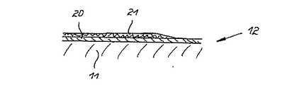
図3は、板形モールド1またはチューブ形モールド6のような鋳型12あるいは鋳造ロールまたは鋳造ローラのような一緒に動く図示していないモールドの銅製基材銅11の縦断面を示している。この基材11には、例えば酸化アルミニウム(Al2 O3 )からなる単層の拡散バリヤ層13が被覆されている。
【0030】
図4において、鋳型12の銅製基材が11で示してある。基材11には多層の層14が被覆されている。この多層の層は本実施の形態では、基材11に接触する窒化クロム(CrN)製の層15と、酸化アルミニウム(Al2 O3 )製の層16と、窒化チタン(TiN)製の被覆層としての層17とからなっている。
【0031】
図5において同様に、鋳型12の銅製基材が11で示してある。基材11には例えば窒化アルミニウム(AlN)製の単層の拡散バリヤ層18が被覆されている。更に、例えばクロムおよび/またはニッケル製の単層の摩耗層19が、銅製の基材11から拡散バリヤ層18への移行範囲に設けられている。
【0032】
図6は鋳型12の銅製基材11を示している。この基材にはクロム製の保護層20が被覆されている。この保護層は更に、厚さが保護層の表面で終わっている、例えば酸化アルミニウム(Al2 O3 )製の拡散バリヤ層21を備えている。
【図面の簡単な説明】
【図1】モールド板の鋳造板の概略的な正面図である。
【図2】モールド管の概略的な斜視図である。
【図3】鋳型の基材に被覆された拡散バリヤ層の縦断面図である。
【図4】鋳型の基材に被覆された多層の縦断面図である。
【図5】中間層を有する、鋳型の基材に被覆された単層の拡散バリヤ層の縦断面図である。
【図6】鋳型の基材の保護層に被覆されたバリヤ層の縦断面図である。
【符号の説明】
1 モールド板
2 モールド板1の範囲
3 拡散バリヤ層
4 湯面
5 モールド板の上側エッジ
6 チューブ形モールド
7 拡散バリヤ層
8 チューブ形モールド6の範囲
9 チューブ形モールド6の上側
10 湯面
11 鋳型12の基材
12 鋳型
13 拡散バリヤ層
14 多層
15 多層14の層
16 多層14の層
17 多層14の層
18 拡散バリヤ層
19 摩耗層
20 保護層
21 拡散バリヤ層[0001]
TECHNICAL FIELD OF THE INVENTION
The present invention relates to a copper mold for continuously casting molten steel in the presence of zinc and / or sulfur.
[0002]
[Prior art]
When a copper mold is used to continuously cast molten steel, the area of contact with the molten steel, which undergoes maximum thermal stress in the presence of zinc and / or sulfur, is quickly damaged.
[0003]
In doing so, zinc, for example, as a component of molten automotive scrap iron (zinc as a corrosion inhibitor), reacts with the hot copper surface to form a brittle α / β / γ brass phase in a diffusion process. This brass phase will flake off, resulting in the formation of cracks.
[0004]
For example, the sulfur present by casting aids reacts with copper to form large volumes of brittle copper sulfide. This copper sulfide also falls off. Therefore, the notch effect caused by localized corrosion is a typical starting point for crack formation.
[0005]
[Problems to be solved by the invention]
Starting from the state of the art, the problem underlying the present invention is that in the presence of zinc and / or sulfur, the life of the copper mold is significantly increased without significantly affecting the heat flow and thus the cooling power. An object of the present invention is to provide a copper mold for continuously casting molten steel.
[0006]
[Means for Solving the Problems]
This object is achieved according to the invention by the features of claim 1.
[0007]
According to this feature, the copper mold is provided with a diffusion barrier layer in the area of contact with the molten steel where it is subjected to maximum thermal stress.
[0008]
At least a single such diffusion barrier layer consists, for example, of a metallic material / metalloid material according to claim 2. The solubility of this material with zinc and / or sulfur is negligible in the range of operating temperatures. This material particularly includes ruthenium (Ru), rhenium (Re), tantalum (Ta), silicon (Si), boron (B), tungsten (W), chromium (Cr), and niobium (Nb). If only zinc is present, then molybdenum (Mo), titanium (Ti), rhodium (Rh) and tellurium (Te) can be used.
[0009]
The diffusion barrier layer can be coated directly on the copper surface of the copper mold by a CVD (chemical vapor deposition) or PVD (physical vapor deposition) process.
[0010]
Further, the diffusion barrier layer may be coated with a chrome or other electroplated layer.
[0011]
Furthermore, the diffusion barrier layer can be formed as an intermediate layer before coating with a wear layer, for example of chromium and / or nickel.
[0012]
The choice of layer type is determined by two factors. On the one hand, the priority purpose of the diffusion barrier must be fulfilled. On the other hand, the unavoidable premise of good adhesion as an intermediate or cover layer must be fulfilled.
[0013]
Another method of forming the diffusion barrier layer is chromium oxide as a cover layer. The solubility of this chromium oxide with zinc and / or sulfur is negligible in the range of operating temperatures of the copper mold. The chromium oxide can be produced, for example, by thermally / chemically treating the chromium coating in an oxidizing atmosphere. Along with this, not only the surface itself prevents the diffusion of zinc and / or sulfur into the chromium by the oxide, but also the micro-cracks and macro-cracks of the chromium coating, which are typically always present, are closed by the oxide. .
[0014]
Furthermore, within the scope of the invention, a layer of at least one type of chromium can be deposited as a diffusion barrier layer. For this purpose, a so-called crack-free hard chromium layer, a micro-cracked hard chromium layer and a standardized hard chromium layer can be combined. The combination is made such that cracks do not penetrate from the surface of the layer to the substrate or during use. For example, a layer structure comprising a crack-free chromium or microcracked chromium intermediate layer on which a cover layer made of standard hard chromium is applied is particularly suitable.
[0015]
According to the invention, furthermore, a layer consisting of carbide, nitride, boride or oxide and mixtures thereof, for example based on titanium / aluminum (Ti / Al) and chromium (Cr), is formed as a diffusion barrier layer. In this composition, carbides, nitrides and borides are preferably suitable as intermediate layers. Oxide can be used as a cover layer. In the present invention, in particular, aluminum nitride (AlN), aluminum oxide (Al 2 O 3 ), chromium carbide (CrC), chromium nitride (CrN), titanium carbide (TiC), titanium nitride (TiN), and titanium nitride carbon (TiCN) It is preferable to use titanium aluminum nitride (TiAlN) and titanium boride (TiB 2 ).
[0016]
The diffusion barrier layer can also be formed by coating an aluminum compound, for example, aluminum nitrate, on the surface of a copper mold, for example, a chromium-plated surface. The coating completely wets and infiltrates the surface layer of the mold with the saline solution. By annealing at an appropriate temperature, decomposition into γ-aluminum oxide (Al 2 O 3 ) occurs over the entire surface and in microcracks and open pores. Again, diffusion of zinc and sulfur, and thus brass formation or sulfur corrosion, is prevented. The coating of the aluminum nitrate solution can be carried out by dipping or spraying or by applying with a brush or a roller. Infiltration protection can be enhanced by multiple dippings or applications.
[0017]
Nickel as a wear protective agent and copper as a mold material can be combined, including the diffusion barrier described above.
[0018]
According to the features of
[0019]
According to
[0020]
If the copper mold consists of a tube-shaped or plate-shaped mold, the diffusion barrier layer is preferably coated according to
[0021]
According to
[0022]
The moving mold (casting roll, casting roller) is provided with a diffusion barrier layer according to
[0023]
Internal tests have shown that, according to claim 8, the diffusion barrier layer should be 0.002 to 0.3 mm thick.
[0024]
The preferred thickness of the diffusion barrier layer is from 0.005 to 0.1 mm according to claim 9.
[0025]
According to the features of
[0026]
BEST MODE FOR CARRYING OUT THE INVENTION
Next, the present invention will be described in detail based on the embodiment shown in the drawings.
[0027]
In FIG. 1, reference numeral 1 denotes a copper mold plate. A range 2 indicated by hatching indicates a contact region of molten steel subjected to the maximum thermal stress. This area includes a diffusion barrier layer (diffusion barrier layer, diffusion blocking layer) 3. The bath surface (bath level) 4 is indicated by a dashed line. The
[0028]
FIG. 2 schematically shows a tube-shaped
[0029]
FIG. 3 shows a longitudinal section of a
[0030]
In FIG. 4, the copper base material of the
[0031]
Similarly, in FIG. 5, the copper base material of the
[0032]
FIG. 6 shows the
[Brief description of the drawings]
FIG. 1 is a schematic front view of a cast plate of a mold plate.
FIG. 2 is a schematic perspective view of a mold tube.
FIG. 3 is a longitudinal sectional view of a diffusion barrier layer coated on a base material of a mold.
FIG. 4 is a longitudinal sectional view of a multilayer coated on a base material of a mold.
FIG. 5 is a longitudinal sectional view of a single-layer diffusion barrier layer coated on a mold substrate, having an intermediate layer.
FIG. 6 is a longitudinal sectional view of a barrier layer covered with a protective layer of a mold base material.
[Explanation of symbols]
DESCRIPTION OF SYMBOLS 1 Mold plate 2 Range of mold plate 1
Claims (10)
Applications Claiming Priority (1)
| Application Number | Priority Date | Filing Date | Title |
|---|---|---|---|
| DE10227034A DE10227034A1 (en) | 2002-06-17 | 2002-06-17 | Copper casting mold |
Publications (2)
| Publication Number | Publication Date |
|---|---|
| JP2004017162A true JP2004017162A (en) | 2004-01-22 |
| JP2004017162A5 JP2004017162A5 (en) | 2006-04-06 |
Family
ID=29594593
Family Applications (1)
| Application Number | Title | Priority Date | Filing Date |
|---|---|---|---|
| JP2003171960A Pending JP2004017162A (en) | 2002-06-17 | 2003-06-17 | Cooper mold |
Country Status (11)
| Country | Link |
|---|---|
| US (1) | US7096922B2 (en) |
| EP (1) | EP1375032A1 (en) |
| JP (1) | JP2004017162A (en) |
| KR (1) | KR20040002598A (en) |
| CN (1) | CN1493415A (en) |
| AU (1) | AU2003204752A1 (en) |
| BR (1) | BR0302145A (en) |
| DE (1) | DE10227034A1 (en) |
| MX (1) | MXPA03005439A (en) |
| RU (1) | RU2003117753A (en) |
| TW (1) | TWI270422B (en) |
Cited By (1)
| Publication number | Priority date | Publication date | Assignee | Title |
|---|---|---|---|---|
| JP2007101519A (en) * | 2005-09-07 | 2007-04-19 | Nippon Steel Corp | Device for observing particle shape of magnetic material |
Families Citing this family (9)
| Publication number | Priority date | Publication date | Assignee | Title |
|---|---|---|---|---|
| DE19802809A1 (en) | 1998-01-27 | 1999-07-29 | Km Europa Metal Ag | Liquid-cooled mold |
| WO2008049081A1 (en) * | 2006-10-18 | 2008-04-24 | Inframat Corporation | Casting molds coated for surface enhancement and methods of making them |
| DE102008015096A1 (en) * | 2008-03-19 | 2009-09-24 | Kme Germany Ag & Co. Kg | Process for producing molded parts and molded parts produced by the process |
| US8887532B2 (en) | 2010-08-24 | 2014-11-18 | Corning Incorporated | Glass-forming tools and methods |
| NO338410B1 (en) * | 2013-01-22 | 2016-08-15 | Norsk Hydro As | An electrode for making aluminum and a method for forming the same |
| KR101469173B1 (en) * | 2013-02-26 | 2014-12-04 | 조선대학교산학협력단 | Technology for the Manufacture of hot forming dies with high wear resistance using selective deposition of the superalloy |
| DE102013114326A1 (en) * | 2013-12-18 | 2015-06-18 | Thyssenkrupp Steel Europe Ag | Casting mold for casting molten steel |
| CN110125350A (en) * | 2019-06-04 | 2019-08-16 | 中国重型机械研究院股份公司 | MULTILAYER COMPOSITE copper sheet and preparation method thereof for the wide face of slab caster mould |
| CN114799063B (en) * | 2022-04-28 | 2024-03-22 | 河北科技大学 | Preparation method of titanium carbonitride and chromium carbide synergistically reinforced iron-based composite impeller |
Family Cites Families (20)
| Publication number | Priority date | Publication date | Assignee | Title |
|---|---|---|---|---|
| US4037646A (en) * | 1975-06-13 | 1977-07-26 | Sumitomo Metal Industries, Ltd. | Molds for continuously casting steel |
| DE2634633C2 (en) * | 1976-07-31 | 1984-07-05 | Kabel- und Metallwerke Gutehoffnungshütte AG, 3000 Hannover | Continuous casting mold made of a copper material, especially for continuous casting of steel |
| JPS5841933B2 (en) * | 1977-06-08 | 1983-09-16 | 住友金属工業株式会社 | Continuous casting mold for steel |
| JPS5825534B2 (en) * | 1977-06-10 | 1983-05-27 | 住友金属工業株式会社 | Steel continuous casting mold |
| JPS5823822B2 (en) * | 1977-06-10 | 1983-05-17 | 住友金属工業株式会社 | Continuous casting mold for steel |
| JPS5545514A (en) * | 1978-09-22 | 1980-03-31 | Nippon Steel Corp | Mold for continuous casting of iron and steel |
| DE3038289A1 (en) * | 1980-10-10 | 1982-05-27 | Egon 5650 Solingen Evertz | METHOD FOR DEPOSITING METAL LAYERS ON THE WALLS OF CHILLERS |
| DE3218100A1 (en) * | 1982-05-13 | 1983-11-17 | Kabel- und Metallwerke Gutehoffnungshütte AG, 3000 Hannover | METHOD FOR PRODUCING A TUBE CHOCOLATE WITH A RECTANGULAR OR SQUARE CROSS SECTION |
| JPS5973153A (en) * | 1982-10-21 | 1984-04-25 | Mishima Kosan Co Ltd | Mold for continuous casting and its production |
| JPS59189037A (en) * | 1983-04-08 | 1984-10-26 | Nippon Kokan Kk <Nkk> | Mold for continuous casting |
| US5230380A (en) * | 1988-07-22 | 1993-07-27 | Satosen Co., Ltd. | Molds for continuous casting of steel |
| US5014768A (en) * | 1989-06-30 | 1991-05-14 | Waters & Associates | Chill plate having high heat conductivity and wear resistance |
| DE4041830A1 (en) * | 1990-12-24 | 1992-06-25 | Schloemann Siemag Ag | STEEL MOLDING CHOCOLATE |
| US5499672A (en) * | 1994-06-01 | 1996-03-19 | Chuetsu Metal Works Co., Ltd. | Mold for continuous casting which comprises a flame sprayed coating layer of a tungsten carbide-based wear-resistant material |
| DE19756164A1 (en) * | 1997-12-17 | 1999-06-24 | Km Europa Metal Ag | Process for producing a mold body and mold body |
| JP3853085B2 (en) * | 1998-09-10 | 2006-12-06 | トーカロ株式会社 | Molten metal container and surface treatment method thereof |
| JP2000218346A (en) * | 1999-02-01 | 2000-08-08 | Satosen Co Ltd | Continuous casting mold for steel and its manufacturing method |
| JP3061186B1 (en) * | 1999-11-26 | 2000-07-10 | 株式会社野村鍍金 | Continuous casting mold and method of manufacturing the same |
| US7125612B2 (en) * | 2001-02-20 | 2006-10-24 | Alcoa Inc. | Casting of non-ferrous metals |
| US6672368B2 (en) * | 2001-02-20 | 2004-01-06 | Alcoa Inc. | Continuous casting of aluminum |
-
2002
- 2002-06-17 DE DE10227034A patent/DE10227034A1/en not_active Withdrawn
-
2003
- 2003-06-16 TW TW092116246A patent/TWI270422B/en not_active IP Right Cessation
- 2003-06-16 RU RU2003117753/02A patent/RU2003117753A/en not_active Application Discontinuation
- 2003-06-16 EP EP03013616A patent/EP1375032A1/en not_active Withdrawn
- 2003-06-17 CN CNA031588956A patent/CN1493415A/en active Pending
- 2003-06-17 BR BR0302145-9A patent/BR0302145A/en not_active Application Discontinuation
- 2003-06-17 MX MXPA03005439A patent/MXPA03005439A/en active IP Right Grant
- 2003-06-17 US US10/463,097 patent/US7096922B2/en not_active Expired - Fee Related
- 2003-06-17 KR KR1020030039051A patent/KR20040002598A/en not_active Application Discontinuation
- 2003-06-17 JP JP2003171960A patent/JP2004017162A/en active Pending
- 2003-06-17 AU AU2003204752A patent/AU2003204752A1/en not_active Abandoned
Cited By (2)
| Publication number | Priority date | Publication date | Assignee | Title |
|---|---|---|---|---|
| JP2007101519A (en) * | 2005-09-07 | 2007-04-19 | Nippon Steel Corp | Device for observing particle shape of magnetic material |
| JP4764199B2 (en) * | 2005-09-07 | 2011-08-31 | 新日本製鐵株式会社 | Magnetic particle shape observation device |
Also Published As
| Publication number | Publication date |
|---|---|
| TW200400092A (en) | 2004-01-01 |
| AU2003204752A1 (en) | 2004-01-15 |
| CN1493415A (en) | 2004-05-05 |
| MXPA03005439A (en) | 2005-02-14 |
| BR0302145A (en) | 2004-09-08 |
| RU2003117753A (en) | 2005-01-10 |
| EP1375032A1 (en) | 2004-01-02 |
| TWI270422B (en) | 2007-01-11 |
| US7096922B2 (en) | 2006-08-29 |
| US20030230394A1 (en) | 2003-12-18 |
| KR20040002598A (en) | 2004-01-07 |
| DE10227034A1 (en) | 2003-12-24 |
Similar Documents
| Publication | Publication Date | Title |
|---|---|---|
| US7195817B2 (en) | Diamond coated article and method of its production | |
| US20090023567A1 (en) | Coated Member, Especially Roller, Made of Carbon Fiber-Reinforced Plastic (CFK) for Paper Machines and Printing Presses, and Method for the Production of such a Member | |
| JP2004017162A (en) | Cooper mold | |
| RU98113926A (en) | METHOD FOR APPLYING A MULTI-LAYER COATING ON A SURFACE OF A PRODUCT | |
| US20100243192A1 (en) | Molten metal casting die | |
| JP2005089806A (en) | Layered film having superior abrasion resistance, heat resistance and adhesiveness to substrate, and manufacturing method therefor | |
| JP2008126334A (en) | Wear resistant film and tool having the same | |
| US7096921B2 (en) | Functionally graded alumina-based thin film systems | |
| JP2010534801A (en) | piston ring | |
| JP6429326B2 (en) | Molten metal processing equipment and manufacturing method thereof, protective film and manufacturing method thereof | |
| CN107385374A (en) | Inserted double coatings of intermetallic compound ceramics in a kind of original position and preparation method thereof | |
| JP2004314170A (en) | Casting roll for casting strip composed of aluminum or aluminum alloy | |
| JPH10306362A (en) | Member for hot dip metal bath in which composite sprayed coating excellent in corrosion resistance to hot dip metal and peeling resistance is formed | |
| WO2003064077A1 (en) | Mold copper sheet for continuous casting manufacturing same | |
| JP2006255733A (en) | Mold copper plate for continuous casting | |
| CA2432558A1 (en) | Copper casting mold | |
| JPH0570915A (en) | Roll device for hot-dip plating bath | |
| JP2739409B2 (en) | Manufacturing method of corrosion and wear resistant multilayer metal coating | |
| TWI490344B (en) | Method for manufacturing roll member for molten metal bath | |
| JPH0776763A (en) | Member for galvanization bath excellent in resistance to blocking to alloy layer, its preparation and hot dip galvanization therewith | |
| JP4392888B2 (en) | Manufacturing method of hard coating with excellent corrosion resistance | |
| JP2018004105A (en) | Molten metal treatment device and manufacturing method of the same | |
| TWI426138B (en) | Roller body parts for molten metal baths | |
| EP3918104B1 (en) | Use of a dlc coated part in a galvanizing bath | |
| JPS5925966A (en) | Material for equipment in galvanizing bath |
Legal Events
| Date | Code | Title | Description |
|---|---|---|---|
| A521 | Written amendment |
Free format text: JAPANESE INTERMEDIATE CODE: A523 Effective date: 20060222 |
|
| A621 | Written request for application examination |
Free format text: JAPANESE INTERMEDIATE CODE: A621 Effective date: 20060222 |
|
| A977 | Report on retrieval |
Free format text: JAPANESE INTERMEDIATE CODE: A971007 Effective date: 20080917 |
|
| A131 | Notification of reasons for refusal |
Free format text: JAPANESE INTERMEDIATE CODE: A131 Effective date: 20081014 |
|
| A711 | Notification of change in applicant |
Free format text: JAPANESE INTERMEDIATE CODE: A711 Effective date: 20081219 |
|
| A521 | Written amendment |
Free format text: JAPANESE INTERMEDIATE CODE: A523 Effective date: 20090113 |
|
| A02 | Decision of refusal |
Free format text: JAPANESE INTERMEDIATE CODE: A02 Effective date: 20090303 |