JP2004016845A - Construction method for lining inside of pipe - Google Patents
Construction method for lining inside of pipe Download PDFInfo
- Publication number
- JP2004016845A JP2004016845A JP2002171722A JP2002171722A JP2004016845A JP 2004016845 A JP2004016845 A JP 2004016845A JP 2002171722 A JP2002171722 A JP 2002171722A JP 2002171722 A JP2002171722 A JP 2002171722A JP 2004016845 A JP2004016845 A JP 2004016845A
- Authority
- JP
- Japan
- Prior art keywords
- diameter
- pipe
- small
- diameter pipe
- pig
- Prior art date
- Legal status (The legal status is an assumption and is not a legal conclusion. Google has not performed a legal analysis and makes no representation as to the accuracy of the status listed.)
- Pending
Links
Images

Abstract
Description
【0001】
【発明の属する技術分野】
本発明は、管内ライニング工法に関し、さらに詳しくは、大径管と小径管とを接続してある配管内に、ライニング用のピグを移動させて、前記大径管及び前記小径管の管内にライニング用の未硬化樹脂を塗布する管内ライニング工法に関する。
【0002】
【従来の技術】
この種のライニング工法では、配管内に、ライニング用の未硬化樹脂を充填した後、ライニング用のピグを挿入し、前記ピグを配管内にて移動させることにより、配管内面に所定厚みにて前記未硬化樹脂を塗布するのであるが、大径管と小径管とを接続してある配管では、次のような不具合が生じる。
【0003】
例えば、小径管のうち、大径管との非接続側の端部より、その小径管内に未硬化樹脂を充填した後、小径管の径に適合する小径ピグを挿入し、小径ピグを大径管側へ移動させながら、小径管内に未硬化樹脂を塗布すると、小径管と大径管との接続部にて、配管の内径が小径ピグに対し大きすぎることから、未硬化樹脂の吹き抜けなどが生じ、小径ピグを移動させることができなくなり、大径管内に未硬化樹脂を塗布できないという不具合が生じる。
また、例えば、大径管のうち、小径管との非接続側の端部より、その大径管内に未硬化樹脂を充填した後、大径管の径に適合する大径ピグを挿入し、大径ピグを小径管側へ移動させながら、大径管内に未硬化樹脂を塗布すると、小径管と大径管との接続部にて、配管の内径が大径ピグよりも小さくなることから、大径ピグを移動させることができなくなり、小径管内に未硬化樹脂を塗布できないという不具合が生じる。
【0004】
そこで、従来、この種の大径管と小径管とを接続してある配管の管内ライニング工法では、大径管と小径管とをそれらの接続部にて切断するなどし分割して、小径管の管内に小径ピグを移動させることにより未硬化樹脂を塗布し、大径管の管内に大径ピグを移動させることにより未硬化樹脂を塗布し、そして、その後、大径管と小径管とを再接続することを行っている。
【0005】
【発明が解決しようとする課題】
このため、従来は、大径管と小径管とを切断する作業や、また、大径管と小径管とを再接続する作業などを行う必要があり、施工性があまりよくないという問題があり、改善の余地が残されている。
【0006】
本発明は、上記実情に鑑みてなされたものであって、その目的は、大径管と小径管とを接続してある配管内に未硬化樹脂を塗布する際の施工性を向上させることができる管内ライニング工法を提供するところにある。
【0007】
【課題を解決するための手段】
請求項1記載の発明の特徴手段は、大径管と小径管とを接続してある配管内に、ライニング用のピグを移動させて、前記大径管及び前記小径管の管内にライニング用の未硬化樹脂を塗布する管内ライニング工法であって、
前記小径管内に前記未硬化樹脂を塗布可能な小径ピグを挿入するにあたり、前記小径ピグの前記大径管側への転出を防止するストッパー部材を、前記小径管と前記大径管との接続部に配置しておき、前記小径ピグを、前記小径管の前記接続部側の一端部まで挿入すると共に、前記小径管における前記小径ピグより他端部側に前記未硬化樹脂を充填して、前記小径ピグを前記小径管の前記他端部側に移動させることにより前記小径管の管内に前記未硬化樹脂を塗布する小径管塗布工程と、
前記大径管内で前記未硬化樹脂を塗布可能な大径ピグを、前記大径管の前記接続部側の一端部まで挿入すると共に、前記大径管における前記大径ピグより他端部側に前記未硬化樹脂を充填して、前記大径ピグを前記大径管の前記他端部側に移動させることにより前記大径管の管内に前記未硬化樹脂を塗布する大径管塗布工程とを備えるところにある。
【0008】
〔作用効果〕
本手段によれば、配管をわざわざ小径管と大径管とに切断するなどして分割することなく、小径管及び大径管各々の管内に未硬化樹脂を塗布でき、結果、その施工性を向上させることが可能となる。
【0009】
つまり、小径管塗布工程では、予め、前記ストッパー部材を小径管と大径管との接続部に配置しておいて、前記小径管の前記接続部側ではない方の他端部から前記接続部側の一端部に向けて、小径管用の小径ピグを挿入するので、前記ストッパー部材により、小径ピグが大径管側に転出するのを確実に防止しながら、小径ピグを移動させ、前記接続部側の一端部まで挿入させることができる。そして、このようにして小径管の一端部まで小径ピグを挿入すると共に、その小径ピグより前記接続部側ではない方の他端部側に未硬化樹脂を充填して、その小径ピグを前記接続部側ではない方の他端部側に移動させることで、小径管の管内に未硬化樹脂を塗布することができる。
【0010】
一方、大径管塗布工程では、大径管用の大径ピグを、前記大径管の前記接続部側ではない方の他端部から前記接続部側の一端部に向けて挿入し移動させれば、、前記接続部では管の内径が大径ピグの外径よりも小さくなるので、大径ピグを前記大径管の前記接続部側の一端部まで挿入させることができる。そして、このようにして大径管の一端部まで大径ピグを挿入すると共に、その大径ピグより前記接続部側ではない方の他端部側に未硬化樹脂を充填して、その大径ピグを前記接続部側ではない方の他端部側に移動させることで、大径管の管内に未硬化樹脂を塗布することができる。
【0011】
本手段では、このような小径管塗布工程と大径管塗布工程とを備えるので、配管をわざわざ小径管と大径管とに切断するなどして分割することなく、小径管及び大径管各々の管内に未硬化樹脂を塗布でき、結果、その施工性を向上させることができる。因みに、このような大径管と小径管とが接続される施工対象の配管が、殊に、地中に配設される既設管である場合には、大径管と小径管との接続部付近を掘削する必要がなくなり、有利である。
【0012】
請求項2記載の発明の特徴手段は、上記請求項1の特徴手段に加えて、前記小径管塗布工程にて、前記小径管の前記接続部側の一端部まで前記小径ピグを挿入させるのに、前記小径管の他端部に挿入した前記小径ピグを、前記小径管の他端部から注入する前記未硬化樹脂によって押し込み移動させ、
前記大径管塗布工程にて、前記大径ピグを、前記大径管の前記接続部側の一端部まで挿入させるのに、前記大径管の他端部に挿入した前記大径ピグを、前記大径管の他端部から注入する前記未硬化樹脂によって押し込み移動させるところにある。
【0013】
〔作用効果〕
本手段によれば、小径管塗布工程及び大径管塗布工程において、小径ピグと大径ピグ各々を所定位置まで挿入するにあたり、それぞれ小径管又は大径管の他端部から注入する未硬化樹脂によって小径ピグや大径ピグを押し込み移動させるので、小径ピグや大径ピグ各々の挿入作業を行いながら未硬化樹脂の充填作業も行い、作業工程の簡略化を図ることができ、好適である。
【0014】
請求項3記載の発明の特徴手段は、上記請求項1又は2の特徴手段に加えて、前記ストッパー部材として、可撓性の線状本体の先端部に前記大径ピグを設けてあるものを用いるところにある。
【0015】
〔作用効果〕
可撓性の線状本体の先端部に大径ピグを設けてあるストッパー部材を用いることで、ストッパー部材を、前記小径管と前記大径管との接続部に配置する作業と、大径ピグを、前記大径管の前記接続部側の一端部まで挿入する作業とを同時に行い、作業工程の簡略化を図ることができ、好適である。
【0016】
【発明の実施の形態】
以下に本発明の実施の形態を図面に基づいて説明する。図1,2に、本発明に係る管内ライニング工法の一実施形態の一部断面図を示す。
【0017】
図1,2に示すように、本発明に係る管内ライニング工法の対象となる配管1は、内径の異なる管どうしを接続してなり、内径の大きい直管状の大径管11と内径の小さい直管状の小径管12とを直線状に接続して形成される。尚、本実施形態では、前記大径管11と前記小径管12とは、その長手方向に沿って次第に径が小さくなる縮拡径材13により接続してあるが、このような構成に限定されるものではなく、大径管11と小径管12とはその他各種方法により接続してあってもよい。また、本実施形態では、縮拡径材13の箇所が、大径管11と小径管12との接続部Cに相当する。
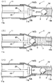
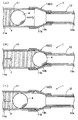
そして、図1(イ)〜(ハ)に例示するようにして、小径管12内に未硬化のエポキシ樹脂等の未硬化樹脂7を塗布可能な小径管12の内径に適合する小径管用の小径ピグ3により小径管塗布工程を行い、図2(ニ)〜(ヘ)に例示するようにして、大径管11内に未硬化樹脂7を塗布可能な大径管11の内径に適合する大径管用の大径ピグ4により大径管塗布工程を行うことで、大径管11及び小径管12の管内面に未硬化樹脂7を塗布する。
【0018】
図1(イ)に示すように、まず、ストッパー部材20を大径管11の接続部C側ではない方の他端部11a側より接続部C内に配置しておき、球形又はほぼ球形の小径ピグ3を小径管12の接続部C側ではない方の他端部12a側より挿入する。
前記ストッパー部材20は、一例として、小径ピグ3を受け止める拡径頭部21と、その拡径頭部21の後方に接続される操作本体22とから構成してあり、操作本体22を操作して、拡径頭部21が接続部Cの所望の位置に配置され、後述するように拡径頭部21にて小径ピグ3の移動を停止し、小径ピグ3が小径管12より脱出するのを防止できるようにしてある。尚、前記ストッパー部材20(拡径頭部21や前記操作本体22)は、小径ピグ3を受け止めその移動を停止させることができる程度の強度を備えていればよく、合成樹脂材料や金属材料など任意の材料から形成すればよい。また、操作本体22は、棒状のものから形成してあってもよいし、または、鋼線やスプリングワイヤ等の線状のものから形成してあってもよい。
【0019】
そして、本実施形態では、図1(イ)に示すように、小径ピグ3の他端部12a側に未硬化樹脂7を注入することで、小径ピグ3を未硬化樹脂7の押し込み圧により接続部C側へと移動させ、図1(ロ)に示すように、小径ピグ3を小径管12の接続部C側の一端部12bまで挿入するのと同時に、未硬化樹脂7を充填する。この際、小径ピグ3は、接続部Cに配置されるストッパー部材20の拡径頭部21に接当することで、移動しすぎることなく停止され、小径管12より脱出することなく、確実に、小径管12の接続部C側の一端部12bまで挿入される。
【0020】
次に、図1(ハ)に示すように、小径管12の接続部C側の一端部12bまで挿入された小径ピグ3を他端部12a側へ移動させることで、小径管12の管内面に未硬化樹脂7が塗布される。
この際、小径ピグ3を他端部12a側へ移動させるにあたっては、任意の方法を用いればよく、例えば、小径管12の他端部12a側より管内を吸引して移動させたり、また、一端部12b側から他端部12a側に向かう加圧流体(空気、スチーム、水等)を供給することにより小径ピグ3を加圧して移動させたり、また、小径ピグ3に索条体等を連結し牽引して移動させるようにすればよい。
【0021】
一方、図2(ニ),(ホ)に示すように、大径管11の接続部C側ではない方の他端部11a側より、ストッパー部材20が取り外され、球形又はほぼ球形の大径ピグ4が前記大径管11の他端部11a側より挿入され、本実施形態では、図に示すように、大径ピグ4の前記大径管11の他端部11a側に未硬化樹脂7を注入することで、大径ピグ4が未硬化樹脂7の押し込み圧により接続部C側へと移動させ挿入されると同時に、未硬化樹脂7が充填される。この際、図2(ホ)に示すように、大径ピグ4の外径が小径管12の内径よりも大きいことから、接続部Cにて大径ピグ4の移動が停止され、大径ピグ4が前記大径管11の接続部C側の一端部11bまで挿入される。
【0022】
次に、図2(ヘ)に示すように、前記大径管11の接続部C側の一端部11bまで挿入された大径ピグ4を他端部11a側へ移動させることで、大径管11の管内面に未硬化樹脂7が塗布される。
この際、大径ピグ4を他端部11a側へ移動させるにあたっては、小径ピグ3の場合と同様に任意の方法を用いればよく、例えば、大径管11の他端部11a側より管内を吸引して移動させたり、また、大径管11の一端部11b側から他端部11a側に向かう加圧流体(空気、スチーム、水等)を供給することにより大径ピグ4を加圧して移動させたり、また、大径ピグ4に索条体等を連結し牽引して移動させるようにすればよい。
【0023】
以上のように、配管1をわざわざ大径管11と小径管12とに切断するなどして分割することなく、大径管11及び小径管12の管内面に未硬化樹脂7を塗布することができ、その施工性を向上させることができる。殊に、このような大径管11と小径管12とが接続される施工対象の配管1が、地中に配設される既設管である場合には、大径管11と小径管12との接続部C付近を掘削する必要がなくなり、有利である。
【0024】
〔別実施形態〕
以下に他の実施形態を説明する。
〈1〉 先の実施形態では、ストッパー部材20の一例として拡径頭部21と操作本体22とからなるものを説明したが、図3に例示するように、スプリングワイヤ等からなる可撓性の線状本体26の先端部に、大径ピグ4を設けてあるものを用いれば、ストッパー部材20を接続部Cに配置する作業と、大径ピグ4を、大径管11の接続部C側の一端部11bまで挿入する作業とを同時に行い、作業工程の簡略化を図ることができ、好適である。
また、ストッパー部材20を接続部Cに配置するにあたっては、線状本体26を軸方向周りに回転させながら押し込むことにより、円滑に大径ピグ4が所定位置に配置されるまで、挿入させることができる。尚、図示しないが、大径ピグ4よりも他端部11a側に未硬化樹脂7を充填し、線状本体26により大径ピグ4を牽引し他端部11a側へ移動させることにより、大径管11に未硬化樹脂7を塗布することができる。
その他は、先の実施形態と同様である。
【0025】
〈2〉 また、先の実施形態では、小径管塗布工程及び大径管塗布工程において、小径ピグと大径ピグ各々を所定位置まで挿入するにあたり、それぞれ小径管又は大径管の他端部から注入する未硬化樹脂によって小径ピグや大径ピグを押し込み移動させる例を示したが、そのような構成に限定されるものではなく、小径ピグや大径ピグを、例えば、吸引して移動させたり、また、加圧して移動させたり、また、牽引して移動させるなどの方法により所定位置まで挿入すると共に、未硬化樹脂を充填するようにしてもよい。
【0026】
〈3〉 先の実施形態では、小径管塗布工程を行った後に、大径管塗布工程を行う例を示したが、そのような順序に限定されるものではなく、小径管塗布工程を行いながら大径管塗布工程を行ってもよいし、また、大径管塗布工程を行った後に、小径管塗布工程を行うようにしてもよい。
【0027】
〈4〉 先の実施形態では、配管1の一例として、直管状の大径管11と直管状の小径管12とを直線状に接続してあるものを示したが、例えば、大径管11や小径管12は各々屈曲部を有しているものでもよいし、また、大径管11と小径管12とを屈曲させて接続してあってもよい。
【0028】
〈5〉 尚、本発明は、任意の用途の配管に適用することができ、配管として、例えば、排水用の配管や、上水道用の配管や、下水道の配管や、ガス供給用の配管に適用することができる。
【図面の簡単な説明】
【図1】本発明に係る管内ライニング工法の小径管塗布工程の一実施形態を示す一部断面図
【図2】本発明に係る管内ライニング工法の大径管塗布工程の一実施形態を示す一部断面図
【図3】本発明に係る管内ライニング工法の別実施形態を示す一部断面図
【符号の説明】
1 配管
3 小径ピグ
4 大径ピグ
7 未硬化樹脂
11 大径管
12 小径管
20 ストッパー部材
26 線状本体
C 接続部[0001]
TECHNICAL FIELD OF THE INVENTION
The present invention relates to an in-pipe lining method, and more specifically, a lining pig is moved in a pipe connecting a large-diameter pipe and a small-diameter pipe, and the lining is moved into the large-diameter pipe and the small-diameter pipe. The present invention relates to a pipe lining method for applying an uncured resin for use in a pipe.
[0002]
[Prior art]
In this type of lining method, after filling the uncured resin for lining in the pipe, inserting a lining pig and moving the pig in the pipe, the pipe has a predetermined thickness on the inner surface of the pipe. Although the uncured resin is applied, the following problem occurs in the pipe connecting the large-diameter pipe and the small-diameter pipe.
[0003]
For example, after filling the uncured resin into the small-diameter pipe from the end of the small-diameter pipe that is not connected to the large-diameter pipe, insert a small-diameter pig that fits the diameter of the small-diameter pipe, and replace the small-diameter pig with the large-diameter pipe. If the uncured resin is applied inside the small-diameter pipe while moving to the pipe side, the blow-through of the uncured resin may occur at the connection between the small-diameter pipe and the large-diameter pipe because the inner diameter of the pipe is too large for the small-diameter pig. As a result, it becomes impossible to move the small-diameter pig, which causes a problem that the uncured resin cannot be applied in the large-diameter pipe.
Also, for example, from the large-diameter pipe, from the end on the non-connection side with the small-diameter pipe, after filling the large-diameter pipe with uncured resin, insert a large-diameter pig that fits the diameter of the large-diameter pipe, If uncured resin is applied inside the large-diameter pipe while moving the large-diameter pig to the small-diameter pipe, the inner diameter of the pipe will be smaller than the large-diameter pig at the connection between the small-diameter pipe and the large-diameter pipe. A problem arises in that the large diameter pig cannot be moved, and the uncured resin cannot be applied in the small diameter pipe.
[0004]
Therefore, in the conventional pipe lining method for connecting a large-diameter pipe and a small-diameter pipe to each other, the large-diameter pipe and the small-diameter pipe are divided by cutting them at a connection portion thereof. The uncured resin is applied by moving the small-diameter pig into the pipe of the large-diameter pipe, and the uncured resin is applied by moving the large-diameter pig into the large-diameter pipe. Going to reconnect.
[0005]
[Problems to be solved by the invention]
For this reason, conventionally, it is necessary to perform operations such as cutting the large-diameter pipe and the small-diameter pipe and re-connecting the large-diameter pipe and the small-diameter pipe, and there is a problem that the workability is not very good. There is room for improvement.
[0006]
The present invention has been made in view of the above circumstances, and an object of the present invention is to improve workability in applying uncured resin to a pipe connecting a large-diameter pipe and a small-diameter pipe. It is to provide an in-pipe lining method.
[0007]
[Means for Solving the Problems]
The characteristic feature of the invention according to
Upon inserting the small diameter pig capable of applying the uncured resin into the small diameter pipe, a stopper member for preventing the small diameter pig from moving out to the large diameter pipe side, a connecting portion between the small diameter pipe and the large diameter pipe The small-diameter pig is inserted up to one end of the small-diameter pipe on the connection portion side, and the other end side of the small-diameter pipe is filled with the uncured resin from the small-diameter pig, A small-diameter pipe applying step of applying the uncured resin to the inside of the small-diameter pipe by moving a small-diameter pig to the other end side of the small-diameter pipe;
A large-diameter pig capable of applying the uncured resin in the large-diameter pipe is inserted up to one end of the large-diameter pipe on the connection portion side, and the other end of the large-diameter pipe is closer to the other end than the large-diameter pig. Filling the uncured resin and moving the large-diameter pig to the other end side of the large-diameter pipe to apply the uncured resin to the inside of the large-diameter pipe. There is to prepare.
[0008]
(Function and effect)
According to this means, the uncured resin can be applied to the inside of each of the small-diameter pipe and the large-diameter pipe without dividing the pipe into a small-diameter pipe and a large-diameter pipe, for example, without dividing the pipe. It can be improved.
[0009]
That is, in the small-diameter pipe coating step, the stopper member is previously arranged at the connection between the small-diameter pipe and the large-diameter pipe, and the other end of the small-diameter pipe that is not on the connection side is connected to the connection section. The small-diameter pig for the small-diameter pipe is inserted toward one end of the small-diameter pipe, so that the stopper is used to move the small-diameter pig while reliably preventing the small-diameter pig from moving out to the large-diameter pipe side. Up to one end on the side. Then, while inserting the small-diameter pig to one end of the small-diameter pipe in this manner, filling the other end side of the small-diameter pig that is not the connection portion side with the uncured resin, and connecting the small-diameter pig to the connection. The uncured resin can be applied to the inside of the small-diameter pipe by moving it to the other end side that is not the section side.
[0010]
On the other hand, in the large-diameter pipe application step, the large-diameter pig for the large-diameter pipe is inserted and moved from the other end of the large-diameter pipe that is not the connection part side to the one end part on the connection part side. For example, since the inside diameter of the pipe is smaller than the outside diameter of the large-diameter pig at the connection portion, the large-diameter pig can be inserted to one end of the large-diameter pipe on the connection portion side. Then, while inserting the large-diameter pig to one end of the large-diameter pipe in this way, filling the other end side of the large-diameter pig that is not the connection portion side with the uncured resin, and The uncured resin can be applied to the inside of the large-diameter pipe by moving the pig to the other end side other than the connection section side.
[0011]
In the present means, since such a small-diameter pipe coating step and a large-diameter pipe coating step are provided, each of the small-diameter pipe and the large-diameter pipe does not need to be divided by cutting the pipe into a small-diameter pipe and a large-diameter pipe. The uncured resin can be applied to the inside of the tube, and as a result, its workability can be improved. Incidentally, in the case where the pipe to be connected to connect such a large-diameter pipe and a small-diameter pipe is an existing pipe installed underground, a connection portion between the large-diameter pipe and the small-diameter pipe is provided. This eliminates the need for excavation in the vicinity, which is advantageous.
[0012]
According to a second aspect of the present invention, in addition to the first aspect, the small-diameter pipe is inserted into the small-diameter pipe up to one end of the small-diameter pipe on the connecting portion side in the small-diameter pipe applying step. The small diameter pig inserted into the other end of the small diameter pipe is pushed and moved by the uncured resin injected from the other end of the small diameter pipe,
In the large-diameter pipe coating step, to insert the large-diameter pig up to one end of the large-diameter pipe on the connection portion side, the large-diameter pig inserted into the other end of the large-diameter pipe, The large-diameter tube is to be pushed and moved by the uncured resin injected from the other end.
[0013]
(Function and effect)
According to this means, in the small-diameter pipe application step and the large-diameter pipe application step, when inserting each of the small-diameter pig and the large-diameter pig to a predetermined position, the uncured resin injected from the other end of the small-diameter pipe or the large-diameter pipe, respectively Since the small-diameter pig and the large-diameter pig are pushed and moved by this, the filling operation of the uncured resin is performed while the small-diameter pig and the large-diameter pig are inserted, which is preferable because the operation process can be simplified.
[0014]
According to a third aspect of the present invention, in addition to the first or second aspect, the stopper is provided with the large-diameter pig at a distal end of a flexible linear body. It is used.
[0015]
(Function and effect)
By using a stopper member provided with a large-diameter pig at a distal end portion of a flexible linear main body, an operation of disposing a stopper member at a connection portion between the small-diameter pipe and the large-diameter pipe; Is preferably performed simultaneously with the operation of inserting up to one end of the large-diameter pipe on the side of the connection portion, thereby simplifying the operation process.
[0016]
BEST MODE FOR CARRYING OUT THE INVENTION
Embodiments of the present invention will be described below with reference to the drawings. 1 and 2 show a partial sectional view of an embodiment of the in-pipe lining method according to the present invention.
[0017]
As shown in FIGS. 1 and 2, a
Then, as illustrated in FIGS. 1A to 1C, a small diameter for a small diameter pipe that fits the inner diameter of the
[0018]
As shown in FIG. 1A, first, the
The
[0019]
In the present embodiment, as shown in FIG. 1A, the
[0020]
Next, as shown in FIG. 1C, the small-
At this time, any method may be used to move the
[0021]
On the other hand, as shown in FIGS. 2 (D) and 2 (E), the
[0022]
Next, as shown in FIG. 2F, the large-
At this time, in order to move the
[0023]
As described above, it is possible to apply the
[0024]
[Another embodiment]
Hereinafter, other embodiments will be described.
<1> In the above embodiment, the
In arranging the
Others are the same as the previous embodiment.
[0025]
<2> Further, in the above embodiment, in the small-diameter pipe application step and the large-diameter pipe application step, when each of the small-diameter pig and the large-diameter pig is inserted to a predetermined position, the other end of the small-diameter pipe or the large-diameter pipe respectively Although the example in which the small-diameter pig or the large-diameter pig is pushed and moved by the uncured resin to be injected is shown, the invention is not limited to such a configuration, and the small-diameter pig or the large-diameter pig is moved, for example, by suction. Alternatively, it may be inserted to a predetermined position by a method of moving by pressurizing or moving by pulling, and may be filled with an uncured resin.
[0026]
<3> In the above embodiment, the example in which the large-diameter tube coating process is performed after the small-diameter tube coating process is performed is described. However, the order is not limited to such an order. The large-diameter tube coating process may be performed, or the small-diameter tube coating process may be performed after the large-diameter tube coating process.
[0027]
<4> In the above embodiment, as an example of the
[0028]
<5> Note that the present invention can be applied to piping for any use. For example, the present invention is applied to piping for drainage, piping for water supply, piping for sewerage, and piping for gas supply. can do.
[Brief description of the drawings]
FIG. 1 is a partial cross-sectional view showing one embodiment of a small-diameter pipe applying step of the in-pipe lining method according to the present invention. FIG. 2 is an embodiment showing one embodiment of a large-diameter pipe applying step of the in-pipe lining method according to the present invention. FIG. 3 is a partial sectional view showing another embodiment of the in-pipe lining method according to the present invention.
DESCRIPTION OF
Claims (3)
前記小径管内に前記未硬化樹脂を塗布可能な小径ピグを挿入するにあたり、前記小径ピグの前記大径管側への転出を防止するストッパー部材を、前記小径管と前記大径管との接続部に配置しておき、前記小径ピグを、前記小径管の前記接続部側の一端部まで挿入すると共に、前記小径管における前記小径ピグより他端部側に前記未硬化樹脂を充填して、前記小径ピグを前記小径管の前記他端部側に移動させることにより前記小径管の管内に前記未硬化樹脂を塗布する小径管塗布工程と、
前記大径管内で前記未硬化樹脂を塗布可能な大径ピグを、前記大径管の前記接続部側の一端部まで挿入すると共に、前記大径管における前記大径ピグより他端部側に前記未硬化樹脂を充填して、前記大径ピグを前記大径管の前記他端部側に移動させることにより前記大径管の管内に前記未硬化樹脂を塗布する大径管塗布工程とを備える管内ライニング工法。An in-pipe lining method in which a lining pig is moved into a pipe connecting the large-diameter pipe and the small-diameter pipe, and an uncured resin for lining is applied to the large-diameter pipe and the small-diameter pipe. hand,
Upon inserting the small diameter pig capable of applying the uncured resin into the small diameter pipe, a stopper member for preventing the small diameter pig from moving out to the large diameter pipe side, a connecting portion between the small diameter pipe and the large diameter pipe The small-diameter pig is inserted up to one end of the small-diameter pipe on the connection portion side, and the other end side of the small-diameter pipe is filled with the uncured resin from the small-diameter pig, A small-diameter pipe applying step of applying the uncured resin to the inside of the small-diameter pipe by moving a small-diameter pig to the other end side of the small-diameter pipe;
A large-diameter pig capable of applying the uncured resin in the large-diameter pipe is inserted up to one end of the large-diameter pipe on the connection portion side, and the other end of the large-diameter pipe is closer to the other end than the large-diameter pig. Filling the uncured resin and moving the large-diameter pig to the other end side of the large-diameter pipe to apply the uncured resin to the inside of the large-diameter pipe. In-pipe lining method.
前記大径管塗布工程にて、前記大径ピグを、前記大径管の前記接続部側の一端部まで挿入させるのに、前記大径管の他端部に挿入した前記大径ピグを、前記大径管の他端部から注入する前記未硬化樹脂によって押し込み移動させる請求項1記載の管内ライニング工法。In the small-diameter pipe coating step, the small-diameter pig inserted into the other end of the small-diameter pipe is inserted into the other end of the small-diameter pipe to insert the small-diameter pig to one end of the small-diameter pipe on the connection portion side. Press and move by the uncured resin injected from the part,
In the large-diameter pipe coating step, to insert the large-diameter pig up to one end of the large-diameter pipe on the connection portion side, the large-diameter pig inserted into the other end of the large-diameter pipe, The in-pipe lining method according to claim 1, wherein the large-diameter pipe is pushed and moved by the uncured resin injected from the other end of the large-diameter pipe.
Priority Applications (1)
| Application Number | Priority Date | Filing Date | Title |
|---|---|---|---|
| JP2002171722A JP2004016845A (en) | 2002-06-12 | 2002-06-12 | Construction method for lining inside of pipe |
Applications Claiming Priority (1)
| Application Number | Priority Date | Filing Date | Title |
|---|---|---|---|
| JP2002171722A JP2004016845A (en) | 2002-06-12 | 2002-06-12 | Construction method for lining inside of pipe |
Publications (1)
| Publication Number | Publication Date |
|---|---|
| JP2004016845A true JP2004016845A (en) | 2004-01-22 |
Family
ID=31171500
Family Applications (1)
| Application Number | Title | Priority Date | Filing Date |
|---|---|---|---|
| JP2002171722A Pending JP2004016845A (en) | 2002-06-12 | 2002-06-12 | Construction method for lining inside of pipe |
Country Status (1)
| Country | Link |
|---|---|
| JP (1) | JP2004016845A (en) |
-
2002
- 2002-06-12 JP JP2002171722A patent/JP2004016845A/en active Pending
Similar Documents
| Publication | Publication Date | Title |
|---|---|---|
| US5738146A (en) | Method for rehabilitation of underground piping | |
| JP2004016845A (en) | Construction method for lining inside of pipe | |
| JPH04163025A (en) | Eversion lining method of tube | |
| JP2004041972A (en) | Pig for lining pipe inside and method for lining pipe inside | |
| JP2000161585A (en) | Pipe lining method | |
| JP2730828B2 (en) | Pipe inner surface repair method and apparatus | |
| JP2963375B2 (en) | Repair method for existing pipeline | |
| US5855712A (en) | Method of repairing an existing pipe | |
| JP2000094522A (en) | Method for lining inside of pipe | |
| JP2002213648A (en) | Technique for renewing existing old pipe | |
| JP2003300012A (en) | Method of lining inside of pipe | |
| JP3410354B2 (en) | Repair method for existing pipeline | |
| JP2000274588A (en) | Pipe lining method | |
| JPH11156941A (en) | Flexible tube traction tool | |
| JP2001032991A (en) | Pipe inside lining technique | |
| JPH11170367A (en) | Method for lining inside of pipe | |
| JP3300308B2 (en) | Rehabilitation repair method for existing pipeline | |
| JP2004290806A (en) | Pipe interior lining pig | |
| JPH01171926A (en) | Hard tube lining method of inside of branch pipe part of underground pipe | |
| JPH07122473B2 (en) | Connection method for mounting pipe in old pipe rehabilitation method | |
| JPH0764028B2 (en) | Expansion device for lining tube and inner lining method of pipe using the same | |
| JP2004308898A (en) | Pipe inside lining pig | |
| JP2001108145A (en) | In-pipe lining method | |
| JP2008284735A (en) | Method of installing regeneration pipe and sealing implement used for the method | |
| JPH058296A (en) | Method for lining and reconditioning pipe |