JP2004016566A - Cuff for hemodynamometer - Google Patents
Cuff for hemodynamometer Download PDFInfo
- Publication number
- JP2004016566A JP2004016566A JP2002177273A JP2002177273A JP2004016566A JP 2004016566 A JP2004016566 A JP 2004016566A JP 2002177273 A JP2002177273 A JP 2002177273A JP 2002177273 A JP2002177273 A JP 2002177273A JP 2004016566 A JP2004016566 A JP 2004016566A
- Authority
- JP
- Japan
- Prior art keywords
- side wall
- fluid bag
- cuff
- compression fluid
- wall portion
- Prior art date
- Legal status (The legal status is an assumption and is not a legal conclusion. Google has not performed a legal analysis and makes no representation as to the accuracy of the status listed.)
- Granted
Links
Images


Classifications
-
- A—HUMAN NECESSITIES
- A61—MEDICAL OR VETERINARY SCIENCE; HYGIENE
- A61B—DIAGNOSIS; SURGERY; IDENTIFICATION
- A61B5/00—Measuring for diagnostic purposes; Identification of persons
- A61B5/02—Detecting, measuring or recording pulse, heart rate, blood pressure or blood flow; Combined pulse/heart-rate/blood pressure determination; Evaluating a cardiovascular condition not otherwise provided for, e.g. using combinations of techniques provided for in this group with electrocardiography or electroauscultation; Heart catheters for measuring blood pressure
- A61B5/021—Measuring pressure in heart or blood vessels
- A61B5/022—Measuring pressure in heart or blood vessels by applying pressure to close blood vessels, e.g. against the skin; Ophthalmodynamometers
- A61B5/02233—Occluders specially adapted therefor
Abstract
Description
【0001】
【発明の属する技術分野】
この発明は、生体に装着して血圧を測定する血圧計に関し、より特定的には、上腕や手首に巻回し、その測定部位を圧迫して血圧を測定するのに用いる血圧計用カフの構造に関する。
【0002】
【従来の技術】
生体に装着して血圧を測定する血圧計に用いる血圧計用カフの構造として、たとえば、特開2001−224558に開示されるものが挙げられる。以下、この血圧計用カフの構造、特に血圧計用カフに装着される圧迫用流体袋の構造について、図11および図12を参照して説明する。
【0003】
まず、図11を参照して、従来の圧迫用流体袋200は、生体側に位置する内壁部201と、この内壁部201に対して対向する位置に設けられる外壁部202と、上腕、手首、その他の生体への巻付方向(図11中A方向)に対する両側壁部において、内壁部201と外壁部202とを連結するように設けられ、圧迫用流体袋200の収縮時には、図11に示すように、内側に折畳まれる第1側壁部203および第2側壁部204とを備えている。
【0004】
第1側壁部203は、一端側が内壁部201に連結される内壁側側壁部203aと、一端側が外壁部202に連結される外壁側側壁部203bとを有し、内壁側側壁部203aと外壁側側壁部203bとのそれぞれの他端側同士が連結されて、略Σ状の形態を構成している。第2側壁部204も第1側壁部203と同様に、内壁側側壁部204aと外壁側側壁部204bとを有している。
【0005】
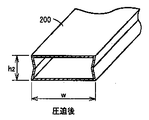
内壁部201および外壁部202の幅は、所定の寸法Wに設けられ、図12に示すように、圧迫用流体袋200が膨張した後も、幅寸法Wは略維持される。収縮時における第1側壁部203および第2側壁部204の折畳み長さd1も、両者同一寸法に設けられ、圧迫用流体袋200が膨張した後は、第1側壁部203および第2側壁部204のいずれも同一長さ伸張して(図11のh1→図12のh2)、圧迫用流体袋200の膨張を可能としている。
【0006】
【発明が解決しようとする課題】
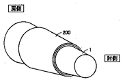
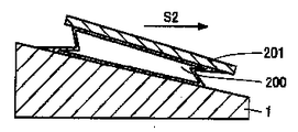
しかしながら、上記構造からなる従来の圧迫用流体袋200においては、以下に示す問題が挙げられる。図13および図14に示すように、カフ固定具201により圧迫用流体袋200を、たとえば上腕1に巻回した場合、上腕1の肘側と肩側とでは腕の太さが異なる。つまり、上腕1はいわゆるテーパ状の表面形状を有していることに起因して、圧迫用流体袋200に流体を送り込み圧迫用流体袋200を膨張させた場合、図15に示すように、カフ固定具201および圧迫用流体袋200が肘側にずれる(図15中S2方向)現象が生じる。この現象について、図16から図19を参照して詳細に説明する。
【0007】
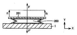
まず、図16を参照して、圧迫用流体袋200をカフ固定具201を用いて、水平な状態の生体1に巻回した場合、圧迫用流体袋200を膨張させるとカフ固定具201は圧迫用流体袋200から押されてFの力を受ける。また、その反作用としてカフ固定具201は圧迫用流体袋200を同量の力F’で押し返す。力Fは、カフ固定具201の各部分で受ける力の合計であり、各部分の力をカフ固定具201の両端部に作用する力f1、f2に代表させると、カフ固定具201および圧迫用流体袋200の対称性を考えれば、f1=f2となる。Fの向きは生体軸方向(図16中X軸方向)に対して垂直であり、生体1から離れる方向(図16中Y軸方向)になると考えられる。
【0008】
そのため、カフ固定具201は、圧迫用流体袋200を生体1の軸(X軸方向)に対して垂直に押すことになり、圧迫用流体袋200およびカフ固定具201のバランスが崩れず、圧迫用流体袋200により生体1が適正に圧迫される。
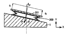
【0009】
次に、図17から図19を参照して、圧迫用流体袋200を、カフ固定具201を用いて、テーパ状の表面を有する生体1に巻回した場合について説明する。まず、図17を参照して、圧迫用流体袋200を膨張させると、上記の場合と同様に、カフ固定具201は圧迫用流体袋200から押されてFの力を受ける。また、その反作用としてカフ固定具201は圧迫用流体袋200を同量の力F’で押し返す。
【0010】
しかし、生体1の表面がテーパ状の場合、生体1に対して垂直な力FはY軸方向に対してα傾くことになる。このとき、カフ固定具201に働く力の釣合において、図18に示すように、X軸方向へずれる力FXが発生する。この力FXが生じることにより、図19に示すように、カフ固定具201をずらす(図中S2方向:上腕の場合には肘側)こととなる。
【0011】
このように、カフ固定具201および圧迫用流体袋200にずれが生じると、圧迫用流体袋200による圧迫中心がずれるため、効果的に動脈に正しい圧力を加えることができない。その結果、圧迫力不足を補うために圧迫用流体袋200は余計に膨らむ必要が生じ、圧迫用流体袋200に余計な張力が発生する。そのため、血圧測定に支障が生じると共に、流体ポンプの小型化が図れないため、血圧計自体の小型化を図れない問題が生じる。
【0012】
したがって、この発明は、上記課題を解決するためになされたものであり、生体(動脈)に圧力を効率良く加えることが可能な、血圧計用カフを提供することを目的とする。
【0013】
【課題を解決するための手段】
この発明に基いた血圧計用カフにおいては、流体の出入により膨張・収縮する圧迫用流体袋を備える血圧計用カフであって、圧迫用流体袋は生体側に位置する内壁部と、内壁部に対して対向する位置に設けられる外壁部と、生体への巻付方向に対する両側壁部において、内壁部と外壁部とを連結するように設けられ、圧迫用流体袋の収縮時には内側に折畳まれる、第1側壁部および第2側壁部とを備え、第1側壁部の伸縮性と第2側壁部の伸縮性とを異ならせたことを特徴とする。
【0014】
この構成により、たとえば、第2側壁部を第1側壁部よりも伸縮性を大きくし、この血圧計用カフを上腕に巻回す場合に、第1側壁部を肩側、第2側壁部を肘側に配置して、圧迫用流体袋に流体を送り込み圧迫用流体袋を膨張させることにより、第2側壁部の方が第1側壁部よりも大きく伸長する。そのため、圧迫用流体袋に押されてカフ固定具に生じる力の傾きが補正され、カフ固定具および圧迫用流体袋を肘側へずらす力が相殺され生じなくなる。その結果、カフ固定具および圧迫用流体袋が肘側へずれなくなり、圧迫用流体袋による圧力を生体に効率良く伝達することが可能になる。また、圧迫用流体袋に余計な張力が発生することもなくなり、流体ポンプの小型化を図ることも可能になる。
【0015】
また、上記血圧計用カフにおいて、第1側壁部の伸縮性と第2側壁部の伸縮性とを異ならせる好ましい形態として、第1側壁部の折畳み長さと第2側壁部の折畳み長さとを異ならせることが挙げられる。また、他の形態として、第1側壁部の伸縮性と第2側壁部の伸縮性とを異ならせるため、第1側壁部の伸縮率と第2側壁部の伸縮率とを異ならせることが挙げられる。
【0016】
【発明の実施の形態】
以下、この発明に基づいた血圧計用カフの実施の形態について、図を参照しながら説明する。なお、本発明の特徴は、血圧計に用いる血圧計用カフにおいて、カフ固定具によって生体に固定される圧迫用流体袋の構造にあるため、ここでは、この圧迫用流体袋の構造について、詳細に説明する。なお、カフ固定具および血圧計の構造については、たとえば、特開2001−224558に開示されるものと同様のものが適用可能である。
【0017】
(圧迫用流体袋100の構造)
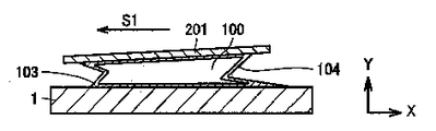
まず、図1および図2を参照して、圧迫用流体袋100の構造について説明する。なお、図1は圧迫用流体袋100の構造を示す横断面図であり、図2は圧迫用流体袋100の全体構造を示す斜視図である。
【0018】
両図を参照して、この発明に基づいた本実施の形態における圧迫用流体袋100は、生体側に位置する内壁部101と、この内壁部101に対して対向する位置に設けられる外壁部102と、上腕、手首、その他の生体への巻付方向(図2中A方向)に対する両側壁部において、内壁部101と外壁部102とを連結するように設けられ、圧迫用流体袋100の収縮時には、図1に示すように、内側に折畳まれる第1側壁部103および第2側壁部104とを備えている。
【0019】
第1側壁部103は、一端側が内壁部101に連結される内壁側側壁部103aと、一端側が外壁部102に連結される外壁側側壁部103bとを有し、内壁側側壁部103aと外壁側側壁部103bとのそれぞれの他端側同士が連結されて、略Σ状の形態を構成している。第2側壁部104も第1側壁部103と同様に、内壁側側壁部104aと外壁側側壁部104bとを有している。
【0020】
本実施の形態においては、内壁部101、外壁部102、第1側壁部103、および第2側壁部104は、すべて同一材料から形成され、たとえば、厚さ約0.3mm程度の塩化ビニル、ウレタン等が用いられる。
【0021】
また、内壁部101および外壁部102の幅は、所定の寸法W(たとえば、約130mm程度に設けられ、圧迫用流体袋100が膨張した後も、幅寸法Wは略維持される。
【0022】
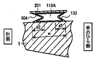
本実施の形態の特徴的構造として、収縮時における第1側壁部103の折畳み長さd1と第2側壁部104の折畳み長さd2とが異なるように設けられている。具体的には、第1側壁部103の折畳み長さd1よりも第2側壁部104の折畳み長さd2の方が長くなるように設けている。たとえば、d1=約25mm、d2=約30mm程度である。
【0023】
ここで、図3はこの圧迫用流体袋100をカフ固定具201により上腕1に巻回し、圧迫用流体袋100が膨張していない状態を示し、図4はこの圧迫用流体袋100をカフ固定具201により上腕1に巻回し、圧迫用流体袋100が膨張している状態を示している。
【0024】
図3および図4を比較して分かるように、圧迫用流体袋100が膨張した後は、第1側壁部103よりも第2側壁部104の方が長く伸張するように(図4のh1<h2)、圧迫用流体袋100の膨張を可能としている。これにより、カフ固定具201がほぼ、生体軸方向(図4中X軸方向)と平行になっているこが確認できる。
【0025】
ここで、図5から図8を参照して、圧迫用流体袋100の膨張における作用について詳細に説明する。なお、図5から図8は、圧迫用流体袋100の膨張における作用を説明するための第1から4模式図である。
【0026】
まず、図5を参照して、圧迫用流体袋100を水平状態にある生体1に巻回した場合を考える。圧迫用流体袋100内に流体を送り込み、圧迫用流体袋100を膨張させた場合、各部分の力をカフ固定具201の両端部に作用する力f1、f2に代表させると、第2側壁部104の方が長く伸張するため、f1<f2となる。そのため、圧迫用流体袋100に押されてカフ固定具201に生じる力Fは、生体軸方向(図5中X軸方向)に対してα傾いた方向に向いて生じる。この状態で、力の釣合を考えると、図6に示すように、−X軸方向へずれる力F−Xが発生する。したがって、この力F−Xが生じることにより、カフ固定具201は、図7に示すように、−X方向(図7中S1方向)にずれることになる。
【0027】
次に、圧迫用流体袋100をテーパ状態にある生体1に巻回した場合を考える。この場合には、図18で説明しように、カフ固定具201にはX軸方向へずれる力FXが発生する。しかし、本実施の形態における圧迫用流体袋100においては、上述したように、−X軸方向へずれる力F−Xが発生することから、FXとF−Xとが相反する方向に働く結果、カフ固定具201にはX軸方向へず力が見かけ上働かないことになる。その結果、図8に示すように、圧迫用流体袋100に押されてカフ固定具201に生じる力Fは、生体軸方向(図8中X軸方向)に対して垂直方向に働くことになる(図8中Y軸方向)。
【0028】
その結果、カフ固定具201および圧迫用流体袋100が肘側へずれなくなり、圧迫用流体袋100による圧力を生体1に効率良く伝達することが可能になる。また、圧迫用流体袋100に余計な張力が発生することもなくなり、流体ポンプの小型化、さらには圧力計の小型化を図ることが可能になる。
【0029】
なお、上記実施の形態においては、上腕部に巻回される血圧計用カフの場合について述べたが、たとえば、図9に示すように、手首部において、橈骨動脈のみを局所的に圧迫する圧迫用流体袋100Aへの適用も可能である。
【0030】
手首部の局所圧迫に適用する圧迫用流体袋100Aの場合には、図10に示すように、手のひら側よりも肘側の方が細くなるため、手のひら側に第1側壁部103を配置し、肘側に第2側壁部104を配置することにより、上記と同様の作用効果を得ることが可能となる。
【0031】
また、上記実施の形態においては、第1側壁部103と第2側壁部104とは同一部材とし、第1側壁部103の折畳み長さと第2側壁部104の折畳み長さとを異ならせることにより、第1側壁部103の伸縮性と第2側壁部104の伸縮性とを異ならせるようにしたが、他の手段として、第1側壁部103の折畳み長さと第2側壁部104の折畳み長さとが同じであっても、第1側壁部103の伸縮率と第2側壁部104の伸縮率とを異ならせることにより、第1側壁部103の伸縮性と第2側壁部104の伸縮性とを異ならせることも可能である。たとえば、同一部材であっても、両者の厚さを異ならせることや、異なる材料を用いることが考えられる。
【0032】
したがって、今回開示した上記実施の形態はすべての点で例示であって、限定的な解釈の根拠となるものではない。したがって、本発明の技術的範囲は、上記した各実施の形態のみによって解釈されるのではなく、特許請求の範囲の記載に基づいて画定される。また、特許請求の範囲と均等の意味および範囲内でのすべての変更が含まれる。
【0033】
【発明の効果】
この発明に基いた血圧計用カフによれば、カフ固定具および圧迫用流体袋のずれが防止され、圧迫用流体袋による圧力を生体(動脈)に効率良く伝達することが可能になる。また、圧迫用流体袋に余計な張力が発生することがないため、流体ポンプの小型化、さらには圧力計の小型化を図ることが可能になる。
【図面の簡単な説明】
【図1】本実施の形態における圧迫用流体袋100の構造を示す横断面図である。
【図2】本実施の形態における圧迫用流体袋100の全体構造を示す斜視図である。
【図3】本実施の形態における圧迫用流体袋100をカフ固定具201により上腕1に巻回し、圧迫用流体袋100が膨張していない状態を示す模式図である。
【図4】本実施の形態における圧迫用流体袋100をカフ固定具201により上腕1に巻回し、圧迫用流体袋100が膨張した状態を示す模式図である。
【図5】本実施の形態における圧迫用流体袋100の膨張における作用を説明するための第1模式図である。
【図6】本実施の形態における圧迫用流体袋100の膨張における作用を説明するための第2模式図である。
【図7】本実施の形態における圧迫用流体袋100の膨張における作用を説明するための第3模式図である。
【図8】本実施の形態における圧迫用流体袋100の膨張における作用を説明するための第4模式図である。
【図9】他実施の形態における、手首部に圧迫用流体袋100Aを装着する状態を示す図である。
【図10】他実施の形態における、手首部において橈骨動脈のみを局所的に圧迫する圧迫用流体袋100Aを示す図である。
【図11】従来の技術における圧迫用流体袋200の全体構造を示す第1斜視図である。
【図12】従来の技術における圧迫用流体袋200の全体構造を示す第2斜視図である。
【図13】従来の技術における圧迫用流体袋200をカフ固定具201により上腕1に巻回した状態を示す斜視図である。
【図14】従来の技術における圧迫用流体袋200をカフ固定具201により上腕1に巻回し、圧迫用流体袋200が膨張していない状態を示す模式図である。
【図15】従来の技術における圧迫用流体袋200をカフ固定具201により上腕1に巻回し、圧迫用流体袋100が膨張した状態を示す模式図である。
【図16】従来の技術における圧迫用流体袋200の膨張における作用を説明するための第1模式図である。
【図17】従来の技術における圧迫用流体袋200の膨張における作用を説明するための第2模式図である。
【図18】従来の技術における圧迫用流体袋200の膨張における作用を説明するための第3模式図である。
【図19】従来の技術における圧迫用流体袋200の膨張における作用を説明するための第4模式図である。
【符号の説明】
1 上腕(生体)、100,100A 圧迫用流体袋、101 内壁部、102 外壁部、103 第1側壁部、104 第2側壁部、103a,104a 内壁側側壁部、103b,104b 外壁側側壁部、201 カフ固定具。[0001]
TECHNICAL FIELD OF THE INVENTION
BACKGROUND OF THE
[0002]
[Prior art]
As a structure of a cuff for a sphygmomanometer used in a sphygmomanometer that measures blood pressure by being attached to a living body, a structure disclosed in Japanese Patent Application Laid-Open No. 2001-224558 is exemplified. Hereinafter, the structure of the sphygmomanometer cuff, particularly the structure of the compression fluid bag attached to the sphygmomanometer cuff, will be described with reference to FIGS. 11 and 12.
[0003]
First, referring to FIG. 11, a conventional
[0004]
The
[0005]
The widths of the
[0006]
[Problems to be solved by the invention]
However, in the conventional
[0007]
First, referring to FIG. 16, when the
[0008]
Therefore, the
[0009]
Next, a case where the
[0010]
However, when the surface of the
[0011]
When the
[0012]
Therefore, the present invention has been made to solve the above-described problem, and has as its object to provide a cuff for a sphygmomanometer capable of efficiently applying pressure to a living body (artery).
[0013]
[Means for Solving the Problems]
In a cuff for a sphygmomanometer according to the present invention, the cuff for a sphygmomanometer includes a compression fluid bag that expands and contracts due to the inflow and outflow of a fluid, wherein the compression fluid bag includes an inner wall portion located on a living body side, and an inner wall portion. The outer wall provided at a position facing the inner wall and the side walls in the winding direction around the living body are provided so as to connect the inner wall and the outer wall, and are folded inward when the compression fluid bag is contracted. The first side wall and the second side wall are provided, and the elasticity of the first side wall is different from the elasticity of the second side wall.
[0014]
With this configuration, for example, when the second side wall is made to have greater elasticity than the first side wall and the cuff for a sphygmomanometer is wound around the upper arm, the first side wall is shoulder-side and the second side wall is elbow. The second side wall portion is extended more than the first side wall portion by distributing the fluid to the compression fluid bag and inflating the compression fluid bag. Therefore, the inclination of the force applied to the cuff fixing device by being pushed by the compression fluid bag is corrected, and the force of shifting the cuff fixing device and the compression fluid bag to the elbow side is not cancelled. As a result, the cuff fixing device and the compression fluid bag do not shift to the elbow side, and the pressure by the compression fluid bag can be efficiently transmitted to the living body. In addition, unnecessary tension is not generated in the compression fluid bag, and the size of the fluid pump can be reduced.
[0015]
Further, in the blood pressure monitor cuff, as a preferred mode for making the elasticity of the first side wall and the elasticity of the second side wall different, the folded length of the first side wall and the folded length of the second side wall are different. It is mentioned. Further, as another embodiment, in order to make the elasticity of the first side wall different from the elasticity of the second side wall, the elasticity of the first side wall and the elasticity of the second side wall are made different. Can be
[0016]
BEST MODE FOR CARRYING OUT THE INVENTION
Hereinafter, an embodiment of a cuff for a blood pressure monitor based on the present invention will be described with reference to the drawings. The feature of the present invention resides in the structure of the compression fluid bag fixed to the living body by the cuff fixing device in the blood pressure monitor cuff used for the blood pressure monitor. Will be described. In addition, about the structure of a cuff fixing device and a sphygmomanometer, the thing similar to what is disclosed by Unexamined-Japanese-Patent No. 2001-224558 is applicable, for example.
[0017]
(Structure of the compression fluid bag 100)
First, the structure of the
[0018]
Referring to both drawings, a
[0019]
The first
[0020]
In the present embodiment,
[0021]
The width of the
[0022]
As a characteristic structure of the present embodiment, the fold length d1 of the first
[0023]
Here, FIG. 3 shows a state in which the
[0024]
As can be seen by comparing FIGS. 3 and 4, after the
[0025]
Here, with reference to FIG. 5 to FIG. 8, an operation in inflation of the
[0026]
First, referring to FIG. 5, a case where the
[0027]
Next, the case where the
[0028]
As a result, the
[0029]
In the above embodiment, the description has been given of the case of the blood pressure cuff wound around the upper arm. For example, as shown in FIG. 9, the compression for locally compressing only the radial artery at the wrist as shown in FIG. 9. Application to the fluid bag 100A is also possible.
[0030]
In the case of the compression fluid bag 100A applied to local compression of the wrist, as shown in FIG. 10, the elbow side is thinner than the palm side, so the
[0031]
Further, in the above-described embodiment, the
[0032]
Therefore, the above-described embodiment disclosed this time is an example in all respects, and is not a basis for restrictive interpretation. Therefore, the technical scope of the present invention is not defined only by the above embodiments, but is defined based on the description of the claims. In addition, all changes within the meaning and scope equivalent to the claims are included.
[0033]
【The invention's effect】
ADVANTAGE OF THE INVENTION According to the cuff for a sphygmomanometer based on this invention, the displacement of a cuff fixture and a compression fluid bag is prevented, and it becomes possible to transmit the pressure by a compression fluid bag to a living body (artery) efficiently. In addition, since unnecessary tension is not generated in the fluid bag for compression, the size of the fluid pump and the size of the pressure gauge can be reduced.
[Brief description of the drawings]
FIG. 1 is a cross-sectional view showing a structure of a
FIG. 2 is a perspective view showing the overall structure of the
FIG. 3 is a schematic view showing a state in which the
FIG. 4 is a schematic diagram showing a state in which the
FIG. 5 is a first schematic diagram for explaining an operation of the
FIG. 6 is a second schematic diagram for explaining the operation of the
FIG. 7 is a third schematic diagram for explaining an operation of the
FIG. 8 is a fourth schematic diagram for explaining an operation of the
FIG. 9 is a view showing a state in which a compression fluid bag 100A is attached to a wrist in another embodiment.
FIG. 10 is a diagram showing a compression fluid bladder 100A that locally compresses only the radial artery at the wrist according to another embodiment.
FIG. 11 is a first perspective view showing the overall structure of a
FIG. 12 is a second perspective view showing the overall structure of a
FIG. 13 is a perspective view showing a state in which a
FIG. 14 is a schematic view showing a state in which a
FIG. 15 is a schematic diagram showing a state in which a
FIG. 16 is a first schematic diagram for explaining an effect of the conventional technique in inflation of a
FIG. 17 is a second schematic diagram for explaining an effect of the conventional technique in inflation of the
FIG. 18 is a third schematic diagram for explaining an effect of the conventional technique in inflation of the
FIG. 19 is a fourth schematic view for explaining an effect of the conventional technique in inflation of the
[Explanation of symbols]
1 upper arm (living body), 100, 100A compression fluid bag, 101 inner wall, 102 outer wall, 103 first side wall, 104 second side wall, 103a, 104a inner wall side, 103b, 104b outer wall side, 201 Cuff fixture.
Claims (3)
前記圧迫用流体袋は生体側に位置する内壁部と、
前記内壁部に対して対向する位置に設けられる外壁部と、
生体への巻付方向に対する両側壁部において、前記内壁部と前記外壁部とを連結するように設けられ、前記圧迫用流体袋の収縮時には内側に折畳まれる、第1側壁部および第2側壁部とを備え、
前記第1側壁部の伸縮性と前記第2側壁部の伸縮性とを異ならせたことを特徴とする、
血圧計用カフ。A cuff for a sphygmomanometer including a compression fluid bag that expands and contracts due to the inflow and outflow of fluid,
The fluid bag for compression is an inner wall portion located on the living body side,
An outer wall portion provided at a position facing the inner wall portion,
A first side wall portion and a second side wall portion which are provided to connect the inner wall portion and the outer wall portion on both side walls in the winding direction around the living body, and which are folded inward when the compression fluid bag is contracted; With a side wall,
The elasticity of the first side wall is different from the elasticity of the second side wall,
Cuff for sphygmomanometer.
Priority Applications (6)
| Application Number | Priority Date | Filing Date | Title |
|---|---|---|---|
| JP2002177273A JP3815385B2 (en) | 2002-06-18 | 2002-06-18 | Sphygmomanometer cuff |
| ES03012905T ES2237726T3 (en) | 2002-06-18 | 2003-06-06 | BRACELET FOR SPHIGMOMANOMETER. |
| DE60300560T DE60300560T2 (en) | 2002-06-18 | 2003-06-06 | Cuff of a sphygmomanometer |
| EP03012905A EP1374762B1 (en) | 2002-06-18 | 2003-06-06 | Cuff of blood pressure monitor |
| US10/461,868 US6866636B2 (en) | 2002-06-18 | 2003-06-16 | Cuff for blood pressure monitor |
| CNB031491421A CN1206960C (en) | 2002-06-18 | 2003-06-18 | Griding band for hemadynomemeter |
Applications Claiming Priority (1)
| Application Number | Priority Date | Filing Date | Title |
|---|---|---|---|
| JP2002177273A JP3815385B2 (en) | 2002-06-18 | 2002-06-18 | Sphygmomanometer cuff |
Publications (3)
| Publication Number | Publication Date |
|---|---|
| JP2004016566A true JP2004016566A (en) | 2004-01-22 |
| JP2004016566A5 JP2004016566A5 (en) | 2005-09-22 |
| JP3815385B2 JP3815385B2 (en) | 2006-08-30 |
Family
ID=29717468
Family Applications (1)
| Application Number | Title | Priority Date | Filing Date |
|---|---|---|---|
| JP2002177273A Expired - Fee Related JP3815385B2 (en) | 2002-06-18 | 2002-06-18 | Sphygmomanometer cuff |
Country Status (6)
| Country | Link |
|---|---|
| US (1) | US6866636B2 (en) |
| EP (1) | EP1374762B1 (en) |
| JP (1) | JP3815385B2 (en) |
| CN (1) | CN1206960C (en) |
| DE (1) | DE60300560T2 (en) |
| ES (1) | ES2237726T3 (en) |
Cited By (4)
| Publication number | Priority date | Publication date | Assignee | Title |
|---|---|---|---|---|
| JP2009112428A (en) * | 2007-11-02 | 2009-05-28 | A & D Co Ltd | Cuff for pulse wave detection, automatic blood pressure measuring apparatus equipped with it, vascular compliance measuring apparatus, pulse wave velocity measuring apparatus |
| JP2018102743A (en) * | 2016-12-27 | 2018-07-05 | オムロン株式会社 | Pouch-shaped structure and method of manufacturing pouch-shaped structure |
| WO2018146968A1 (en) * | 2017-02-13 | 2018-08-16 | オムロン株式会社 | Bag-shaped structure |
| US11389073B2 (en) | 2017-02-07 | 2022-07-19 | Omron Corporation | Bag-shaped structure, cuff for blood pressure monitor, and blood pressure monitor |
Families Citing this family (30)
| Publication number | Priority date | Publication date | Assignee | Title |
|---|---|---|---|---|
| US7429245B2 (en) * | 2003-07-14 | 2008-09-30 | Welch Allyn, Inc. | Motion management in a fast blood pressure measurement device |
| US7871387B2 (en) | 2004-02-23 | 2011-01-18 | Tyco Healthcare Group Lp | Compression sleeve convertible in length |
| US20060111637A1 (en) * | 2004-11-23 | 2006-05-25 | Jacober Jeffrey M | Wrist-mount blood pressure monitor with auditory feature |
| JP4595526B2 (en) * | 2004-12-20 | 2010-12-08 | オムロンヘルスケア株式会社 | Sphygmomanometer cuff and sphygmomanometer |
| JP4595525B2 (en) | 2004-12-20 | 2010-12-08 | オムロンヘルスケア株式会社 | Sphygmomanometer cuff and sphygmomanometer equipped with the same |
| JP2006218178A (en) * | 2005-02-14 | 2006-08-24 | Omron Healthcare Co Ltd | Cuff for hemadynamometer and hemadynamometer |
| GB0515294D0 (en) | 2005-07-26 | 2005-08-31 | Novamedix Distrib Ltd | Limited durability closure means for an inflatable medical garment |
| US8029451B2 (en) | 2005-12-12 | 2011-10-04 | Tyco Healthcare Group Lp | Compression sleeve having air conduits |
| US7442175B2 (en) * | 2005-12-12 | 2008-10-28 | Tyco Healthcare Group Lp | Compression sleeve having air conduit |
| SE0600202L (en) * | 2006-02-01 | 2007-04-17 | Per Danielsson | Blood Pressure Monitor |
| US20100106029A1 (en) * | 2007-03-28 | 2010-04-29 | Kaz, Incorporated | Arterial blood pressure monitor with a liquid filled cuff |
| US8029450B2 (en) * | 2007-04-09 | 2011-10-04 | Tyco Healthcare Group Lp | Breathable compression device |
| US8016779B2 (en) | 2007-04-09 | 2011-09-13 | Tyco Healthcare Group Lp | Compression device having cooling capability |
| US8162861B2 (en) | 2007-04-09 | 2012-04-24 | Tyco Healthcare Group Lp | Compression device with strategic weld construction |
| USD608006S1 (en) | 2007-04-09 | 2010-01-12 | Tyco Healthcare Group Lp | Compression device |
| US8109892B2 (en) * | 2007-04-09 | 2012-02-07 | Tyco Healthcare Group Lp | Methods of making compression device with improved evaporation |
| US8034007B2 (en) | 2007-04-09 | 2011-10-11 | Tyco Healthcare Group Lp | Compression device with structural support features |
| US8506508B2 (en) | 2007-04-09 | 2013-08-13 | Covidien Lp | Compression device having weld seam moisture transfer |
| US8016778B2 (en) | 2007-04-09 | 2011-09-13 | Tyco Healthcare Group Lp | Compression device with improved moisture evaporation |
| US8070699B2 (en) | 2007-04-09 | 2011-12-06 | Tyco Healthcare Group Lp | Method of making compression sleeve with structural support features |
| US8021388B2 (en) * | 2007-04-09 | 2011-09-20 | Tyco Healthcare Group Lp | Compression device with improved moisture evaporation |
| US8128584B2 (en) | 2007-04-09 | 2012-03-06 | Tyco Healthcare Group Lp | Compression device with S-shaped bladder |
| US8114117B2 (en) | 2008-09-30 | 2012-02-14 | Tyco Healthcare Group Lp | Compression device with wear area |
| US8235923B2 (en) | 2008-09-30 | 2012-08-07 | Tyco Healthcare Group Lp | Compression device with removable portion |
| US8652079B2 (en) | 2010-04-02 | 2014-02-18 | Covidien Lp | Compression garment having an extension |
| US10751221B2 (en) | 2010-09-14 | 2020-08-25 | Kpr U.S., Llc | Compression sleeve with improved position retention |
| US9205021B2 (en) | 2012-06-18 | 2015-12-08 | Covidien Lp | Compression system with vent cooling feature |
| JP6051964B2 (en) * | 2013-03-07 | 2016-12-27 | オムロンヘルスケア株式会社 | Blood pressure measurement cuff and method for manufacturing blood pressure measurement cuff |
| US9743847B2 (en) | 2013-03-15 | 2017-08-29 | St. Luke Medical, Inc. | Blood pressure cuff with tapered bladder |
| JP6172218B2 (en) * | 2015-06-24 | 2017-08-02 | オムロンヘルスケア株式会社 | Fluid bag, blood pressure measurement cuff, blood pressure monitor, and blood pressure measurement method |
Family Cites Families (9)
| Publication number | Priority date | Publication date | Assignee | Title |
|---|---|---|---|---|
| JPS6472726A (en) * | 1987-09-14 | 1989-03-17 | Matsushita Electric Works Ltd | Ischemia cuff of hemomanometer |
| JP2840075B2 (en) * | 1988-10-15 | 1998-12-24 | 松下電工株式会社 | Wrist sphygmomanometer cuff |
| JPH0549529A (en) * | 1991-08-27 | 1993-03-02 | Matsushita Electric Works Ltd | Air mat |
| JP3491412B2 (en) * | 1995-10-26 | 2004-01-26 | 松下電工株式会社 | Cuff band for blood pressure monitor and method for manufacturing the same |
| JPH11342118A (en) * | 1998-06-04 | 1999-12-14 | Citizen Watch Co Ltd | Cuff structure for prohibiting blood |
| US6477651B1 (en) * | 1999-01-08 | 2002-11-05 | Cisco Technology, Inc. | Intrusion detection system and method having dynamically loaded signatures |
| US6245023B1 (en) * | 1999-08-19 | 2001-06-12 | Critikon Company, Llc | Conical blood pressure cuff with rectangular bladder |
| JP3363847B2 (en) * | 1999-09-06 | 2003-01-08 | 日本コーリン株式会社 | Blood pressure measurement device |
| JP3452016B2 (en) * | 2000-02-17 | 2003-09-29 | オムロン株式会社 | Blood pressure cuff |
-
2002
- 2002-06-18 JP JP2002177273A patent/JP3815385B2/en not_active Expired - Fee Related
-
2003
- 2003-06-06 EP EP03012905A patent/EP1374762B1/en not_active Expired - Lifetime
- 2003-06-06 ES ES03012905T patent/ES2237726T3/en not_active Expired - Lifetime
- 2003-06-06 DE DE60300560T patent/DE60300560T2/en not_active Expired - Lifetime
- 2003-06-16 US US10/461,868 patent/US6866636B2/en not_active Expired - Lifetime
- 2003-06-18 CN CNB031491421A patent/CN1206960C/en not_active Expired - Lifetime
Cited By (7)
| Publication number | Priority date | Publication date | Assignee | Title |
|---|---|---|---|---|
| JP2009112428A (en) * | 2007-11-02 | 2009-05-28 | A & D Co Ltd | Cuff for pulse wave detection, automatic blood pressure measuring apparatus equipped with it, vascular compliance measuring apparatus, pulse wave velocity measuring apparatus |
| JP2018102743A (en) * | 2016-12-27 | 2018-07-05 | オムロン株式会社 | Pouch-shaped structure and method of manufacturing pouch-shaped structure |
| WO2018124073A1 (en) * | 2016-12-27 | 2018-07-05 | オムロン株式会社 | Pouch-shaped structure and method of manufacturing pouch-shaped structure |
| US11389073B2 (en) | 2017-02-07 | 2022-07-19 | Omron Corporation | Bag-shaped structure, cuff for blood pressure monitor, and blood pressure monitor |
| WO2018146968A1 (en) * | 2017-02-13 | 2018-08-16 | オムロン株式会社 | Bag-shaped structure |
| JP2018130161A (en) * | 2017-02-13 | 2018-08-23 | オムロン株式会社 | Bag-shaped structure |
| US11272853B2 (en) | 2017-02-13 | 2022-03-15 | Omron Corporation | Bag-shaped structure used in a cuff for blood pressure measurement |
Also Published As
| Publication number | Publication date |
|---|---|
| DE60300560D1 (en) | 2005-06-02 |
| US20040034308A1 (en) | 2004-02-19 |
| DE60300560T2 (en) | 2006-01-19 |
| US6866636B2 (en) | 2005-03-15 |
| ES2237726T3 (en) | 2005-08-01 |
| JP3815385B2 (en) | 2006-08-30 |
| EP1374762A1 (en) | 2004-01-02 |
| CN1470217A (en) | 2004-01-28 |
| EP1374762B1 (en) | 2005-04-27 |
| CN1206960C (en) | 2005-06-22 |
Similar Documents
| Publication | Publication Date | Title |
|---|---|---|
| JP2004016566A (en) | Cuff for hemodynamometer | |
| JP3952957B2 (en) | Cuff for wrist blood pressure monitor | |
| JP3452016B2 (en) | Blood pressure cuff | |
| CN108289622B (en) | Fluid bag, cuff for blood pressure measurement, sphygmomanometer, and blood pressure measurement method | |
| JP4742576B2 (en) | Sphygmomanometer cuff and sphygmomanometer equipped with the same | |
| RU2314746C2 (en) | Cuff for measuring arterial pressure and arterial pressure meter containing cuff | |
| TWI376218B (en) | ||
| JP5145930B2 (en) | Sphygmomanometer cuff and sphygmomanometer | |
| JP3159862U (en) | Sphygmomanometer cuff | |
| JP2006218178A (en) | Cuff for hemadynamometer and hemadynamometer | |
| JP4654641B2 (en) | Sphygmomanometer cuff | |
| JP3922087B2 (en) | Cuff for wrist blood pressure monitor | |
| JP2007307219A (en) | Blood pressure measuring instrument | |
| JPH09117419A (en) | Cuff band for memodynamometer and its manufacture | |
| JP2004065984A (en) | Internal telescopic guide for inflatable air cushion | |
| EP2258259A1 (en) | Blood pressure cuff | |
| JP2006081668A (en) | Cuff for sphygmomanometer | |
| JP2010233655A (en) | Sphygmomanometer | |
| CN108601538B (en) | Soft clamp and cuff for blood pressure measurement provided with same | |
| JP4259182B2 (en) | Biological information measuring device | |
| JP5208655B2 (en) | Biological compression device, manufacturing method thereof, and blood pressure measurement device | |
| US20080119744A1 (en) | Cuff structure for sphygmomanometers | |
| TW201116268A (en) | Fixing element and use of such a fixing element for fixing an object, particularly appendages | |
| JP2009077824A (en) | Compression member | |
| JP2000229070A (en) | Cuff for hemodynamometer |
Legal Events
| Date | Code | Title | Description |
|---|---|---|---|
| A521 | Request for written amendment filed |
Free format text: JAPANESE INTERMEDIATE CODE: A523 Effective date: 20050408 |
|
| A621 | Written request for application examination |
Free format text: JAPANESE INTERMEDIATE CODE: A621 Effective date: 20050408 |
|
| A977 | Report on retrieval |
Free format text: JAPANESE INTERMEDIATE CODE: A971007 Effective date: 20051220 |
|
| A131 | Notification of reasons for refusal |
Free format text: JAPANESE INTERMEDIATE CODE: A131 Effective date: 20051227 |
|
| A521 | Request for written amendment filed |
Free format text: JAPANESE INTERMEDIATE CODE: A523 Effective date: 20060222 |
|
| TRDD | Decision of grant or rejection written | ||
| A01 | Written decision to grant a patent or to grant a registration (utility model) |
Free format text: JAPANESE INTERMEDIATE CODE: A01 Effective date: 20060516 |
|
| A61 | First payment of annual fees (during grant procedure) |
Free format text: JAPANESE INTERMEDIATE CODE: A61 Effective date: 20060529 |
|
| R150 | Certificate of patent or registration of utility model |
Free format text: JAPANESE INTERMEDIATE CODE: R150 Ref document number: 3815385 Country of ref document: JP Free format text: JAPANESE INTERMEDIATE CODE: R150 |
|
| FPAY | Renewal fee payment (event date is renewal date of database) |
Free format text: PAYMENT UNTIL: 20090616 Year of fee payment: 3 |
|
| FPAY | Renewal fee payment (event date is renewal date of database) |
Free format text: PAYMENT UNTIL: 20100616 Year of fee payment: 4 |
|
| FPAY | Renewal fee payment (event date is renewal date of database) |
Free format text: PAYMENT UNTIL: 20100616 Year of fee payment: 4 |
|
| FPAY | Renewal fee payment (event date is renewal date of database) |
Free format text: PAYMENT UNTIL: 20110616 Year of fee payment: 5 |
|
| FPAY | Renewal fee payment (event date is renewal date of database) |
Free format text: PAYMENT UNTIL: 20110616 Year of fee payment: 5 |
|
| FPAY | Renewal fee payment (event date is renewal date of database) |
Free format text: PAYMENT UNTIL: 20120616 Year of fee payment: 6 |
|
| FPAY | Renewal fee payment (event date is renewal date of database) |
Free format text: PAYMENT UNTIL: 20130616 Year of fee payment: 7 |
|
| LAPS | Cancellation because of no payment of annual fees |