JP6051964B2 - Blood pressure measurement cuff and method for manufacturing blood pressure measurement cuff - Google Patents
Blood pressure measurement cuff and method for manufacturing blood pressure measurement cuff Download PDFInfo
- Publication number
- JP6051964B2 JP6051964B2 JP2013045788A JP2013045788A JP6051964B2 JP 6051964 B2 JP6051964 B2 JP 6051964B2 JP 2013045788 A JP2013045788 A JP 2013045788A JP 2013045788 A JP2013045788 A JP 2013045788A JP 6051964 B2 JP6051964 B2 JP 6051964B2
- Authority
- JP
- Japan
- Prior art keywords
- curler
- blood pressure
- air bag
- cuff
- pressure measurement
- Prior art date
- Legal status (The legal status is an assumption and is not a legal conclusion. Google has not performed a legal analysis and makes no representation as to the accuracy of the status listed.)
- Active
Links
Images


Classifications
-
- A—HUMAN NECESSITIES
- A61—MEDICAL OR VETERINARY SCIENCE; HYGIENE
- A61B—DIAGNOSIS; SURGERY; IDENTIFICATION
- A61B5/00—Measuring for diagnostic purposes; Identification of persons
- A61B5/02—Detecting, measuring or recording pulse, heart rate, blood pressure or blood flow; Combined pulse/heart-rate/blood pressure determination; Evaluating a cardiovascular condition not otherwise provided for, e.g. using combinations of techniques provided for in this group with electrocardiography or electroauscultation; Heart catheters for measuring blood pressure
- A61B5/021—Measuring pressure in heart or blood vessels
- A61B5/022—Measuring pressure in heart or blood vessels by applying pressure to close blood vessels, e.g. against the skin; Ophthalmodynamometers
- A61B5/02233—Occluders specially adapted therefor
-
- A—HUMAN NECESSITIES
- A61—MEDICAL OR VETERINARY SCIENCE; HYGIENE
- A61B—DIAGNOSIS; SURGERY; IDENTIFICATION
- A61B5/00—Measuring for diagnostic purposes; Identification of persons
- A61B5/68—Arrangements of detecting, measuring or recording means, e.g. sensors, in relation to patient
- A61B5/6801—Arrangements of detecting, measuring or recording means, e.g. sensors, in relation to patient specially adapted to be attached to or worn on the body surface
- A61B5/683—Means for maintaining contact with the body
-
- A—HUMAN NECESSITIES
- A61—MEDICAL OR VETERINARY SCIENCE; HYGIENE
- A61B—DIAGNOSIS; SURGERY; IDENTIFICATION
- A61B2562/00—Details of sensors; Constructional details of sensor housings or probes; Accessories for sensors
- A61B2562/12—Manufacturing methods specially adapted for producing sensors for in-vivo measurements
Landscapes
- Health & Medical Sciences (AREA)
- Life Sciences & Earth Sciences (AREA)
- Cardiology (AREA)
- Vascular Medicine (AREA)
- Surgery (AREA)
- Medical Informatics (AREA)
- Physics & Mathematics (AREA)
- Veterinary Medicine (AREA)
- Biophysics (AREA)
- Pathology (AREA)
- Engineering & Computer Science (AREA)
- Biomedical Technology (AREA)
- Heart & Thoracic Surgery (AREA)
- Public Health (AREA)
- Molecular Biology (AREA)
- General Health & Medical Sciences (AREA)
- Animal Behavior & Ethology (AREA)
- Physiology (AREA)
- Ophthalmology & Optometry (AREA)
- Dentistry (AREA)
- Measuring Pulse, Heart Rate, Blood Pressure Or Blood Flow (AREA)
Description
この発明は、血圧測定用カフに関し、より詳しくは、被測定部位に沿う形状を有するカーラを備えた血圧測定用カフに関する。 The present invention relates to a blood pressure measurement cuff, and more particularly to a blood pressure measurement cuff provided with a curler having a shape along a measurement site.
また、この発明は、血圧測定用カフの製造方法に関し、より詳しくは、被測定部位に沿う形状を有するカーラを備えた血圧測定用カフの製造方法に関する。 The present invention also relates to a method for manufacturing a blood pressure measurement cuff, and more particularly to a method for manufacturing a blood pressure measurement cuff provided with a curler having a shape along a region to be measured.
従来、この種の装置としては、例えば特許文献1(国際公開第2011/081029号パンフレット)に示されるように、外布(外装カバー)と空気袋との間にカーラを備えた血圧測定用カフがある。このカーラは、自然状態で腕などの被測定部位に沿う形状を有する。これにより、カフの被測定部位への装着が容易になっている。 Conventionally, as this type of device, as shown in, for example, Patent Document 1 (International Publication No. 2011/081029 pamphlet), a blood pressure measurement cuff provided with a curler between an outer cloth (exterior cover) and an air bag. There is. This curler has a shape along a measurement site such as an arm in a natural state. Thereby, the cuff can be easily attached to the measurement site.
図29は、特許文献1に示されるカフの展開状態の平面図であり、図30は、図29の線A−A’に沿った断面図である。 29 is a plan view of the unfolded state of the cuff shown in Patent Document 1, and FIG. 30 is a cross-sectional view taken along line A-A ′ in FIG. 29.
図29および図30を参照すれば、カフ900は、流体袋(空気袋)が形成される領域R1においては、空気袋903およびカーラ904が、第1外布901aおよび第1内布901bが形成する袋状外装カバーに内包されている。
29 and 30, in the region R1 where the fluid bag (air bag) is formed, the
カフ900においては、第1外布901aとカーラ904との間、および、カーラ904と空気袋903との間に、それぞれすべりのよい内部シート905aおよび905bが追加されている。
In the
カフ900において、2枚の内部シート905a,905bが追加されるのは、以下の理由による。空気袋903への空気の供給または排出に伴い、空気袋903は変形しようとする。だが、しばしば、空気袋903は、他の部材との接点において生じる摩擦力によってその変形が阻まれる。
In the
そして、当該摩擦力が該接点における最大静止摩擦力に等しくなるまで、つまり、ずれ応力の大きさが最大静止摩擦力の大きさに等しくなるまで、その変形は阻止される。そして、接点に作用するずれ応力の大きさが最大静止摩擦力の大きさを超えた途端、空気袋903に急激な変形が生じ、これに起因して、比較的大きな雑音が発生する。この比較的大きな雑音は、しばしば、血圧測定に悪影響を及ぼす。
The deformation is prevented until the frictional force becomes equal to the maximum static frictional force at the contact, that is, until the magnitude of the deviation stress becomes equal to the maximum static frictional force. Then, as soon as the magnitude of the shear stress acting on the contact exceeds the magnitude of the maximum static frictional force, abrupt deformation occurs in the
そのため、カフ900においては、血圧測定に悪影響を及ぼす雑音が発生することを防止するため、雑音の発生が懸念される部材間に2枚の内部シート905a,905bが追加されている。
Therefore, in the
しかしながら、従来技術においては、雑音の発生を抑制するために、内部シート905a,905b(図30)といった追加的な部材を必要としている。そのため、従来技術では、製造工程の複雑化および費用増、ならびに、材料コストの増大、といった事態を招いていた。
However, in the prior art, additional members such as the
そこで、この発明の課題は、より簡単な構成で、膨縮時の雑音の発生を抑制できる血圧測定用カフを提供することにある。 Accordingly, an object of the present invention is to provide a blood pressure measurement cuff that can suppress the generation of noise during expansion and contraction with a simpler configuration.
また、この発明の課題は、より簡単な構成で膨縮時の雑音の発生を抑制できる血圧測定用カフの製造方法を提供することにある。 Another object of the present invention is to provide a method for manufacturing a blood pressure measurement cuff that can suppress the generation of noise during expansion and contraction with a simpler configuration.
上記課題を解決するため、この発明の一態様である血圧測定用カフは、
被測定部位を取り巻くように装着される血圧測定用カフであって、
自然状態において被測定部位に沿うように湾曲し可撓性をもつカーラと、
カーラの内側と外側を取り巻いてカーラを内包する空気袋と、
空気袋の被測定部位側の外面に付けられた内布と、
空気袋の被測定部位と反対側の外面に付けられた外布と、
を有することを特徴とする。
In order to solve the above problems, a blood pressure measurement cuff according to one aspect of the present invention is provided.
A blood pressure measurement cuff attached to surround the measurement site,
A curler that is curved and flexible along the measurement site in the natural state;
An air bag surrounding the inside and outside of the curler and enclosing the curler;
An inner cloth attached to the outer surface of the measurement site side of the air bag;
An outer cloth affixed to the outer surface of the air bag opposite to the measurement site;
It is characterized by having.
この発明の一態様である血圧測定用カフでは、カーラは、自然状態で腕などの被測定部位に沿う形状を有する。これにより、カフの被測定部位への装着が容易になっている。また、このカフでは、空気袋は内布および外布に付けられ、カーラは空気袋に内包されている。よって、空気袋内に周囲環境の気圧よりも高い空気(被圧空気)が含まれる限りにおいて、空気袋には、カーラから遠ざかるように変形および変位させようとする力が作用する。したがって、血圧測定におけるカフの膨縮に際しては、カーラが空気袋によって強く押さえつけられて圧迫されることがない。よって、カーラと空気袋との接点において、大きなずれ応力に拮抗しうるような大きな静止摩擦力が生じることはない。それ故、同接点において、急激なずれ変形が生じて血圧測定を妨害する程度に大きな雑音が発生することがない。また、空気袋と内布および外布とは付けられているため、膨縮時には、三者は一体的に変形する。よって、カフの膨縮に際して空気袋と内布および外布との相対的位置関係がずれることもない。よって、本血圧測定用カフでは、血圧測定の妨げとなるような膨縮時の雑音の発生が抑制される。 In the blood pressure measurement cuff according to one aspect of the present invention, the curler has a shape along a measurement site such as an arm in a natural state. Thereby, the cuff can be easily attached to the measurement site. In this cuff, the air bag is attached to the inner cloth and the outer cloth, and the curler is included in the air bag. Therefore, as long as the air bag contains air (pressure air) that is higher than the atmospheric pressure of the surrounding environment, a force to deform and displace the air bag so as to move away from the curler acts. Therefore, when the cuff is inflated or contracted in blood pressure measurement, the curler is not strongly compressed by the air bag. Therefore, at the contact point between the curler and the air bag, a large static friction force that can antagonize a large shear stress does not occur. Therefore, at the same point of contact, a large amount of noise is not generated to the extent that sudden displacement deformation occurs and disturbs blood pressure measurement. Moreover, since the air bag, the inner cloth, and the outer cloth are attached, at the time of expansion and contraction, the three are integrally deformed. Therefore, the relative positional relationship between the air bag and the inner and outer cloths does not shift when the cuff is inflated and contracted. Therefore, in this blood pressure measurement cuff, the occurrence of noise during expansion and contraction that hinders blood pressure measurement is suppressed.
一実施形態の血圧測定用カフでは、カーラの被測定部位を取り巻く周方向に関する少なくとも1つの周端において、周方向に対して略垂直な幅方向の中央部がその幅方向両側に存するコーナ部よりも周方向に関して後退していることを特徴とする。 In the blood pressure measurement cuff according to the embodiment, at least one circumferential end in the circumferential direction surrounding the measurement target portion of the curler is more than a corner portion in which the central portion in the width direction substantially perpendicular to the circumferential direction exists on both sides in the width direction. Is also retracted in the circumferential direction.
この一実施形態の血圧測定用カフでは、カーラの周端において、幅方向中央部がコーナ部よりも後退している。これにより、当該中央部近傍に位置する空気袋の周縁部では、空気袋がカーラ中央部に入り込むように変位および変形することが可能となっている。そのため、空気袋の膨張時には、上記した空気袋の周縁部が中央部に近づくように、そして、周縁部近傍の空気袋は被測定部位に向かって大きく変形することができ、もって、当該空気袋周縁部近傍においてもカフが被測定部位をよく圧迫することが可能となる。 In the blood pressure measurement cuff according to this embodiment, the central portion in the width direction recedes from the corner portion at the peripheral end of the curler. Thereby, in the peripheral part of the air bag located in the vicinity of the central part, the air bag can be displaced and deformed so as to enter the central part of the curler. Therefore, when the air bag is inflated, the air bag in the vicinity of the peripheral part can be greatly deformed toward the measurement site so that the peripheral part of the air bag approaches the central part. Even in the vicinity of the peripheral edge, the cuff can press the measurement site well.
一実施形態の血圧測定用カフでは、空気袋は、2枚の気密性シート部材の周縁部が溶着されることにより形成されていることを特徴とする。 In the blood pressure measurement cuff of one embodiment, the air bag is formed by welding the peripheral portions of two airtight sheet members.
この一実施形態の血圧測定用カフでは、溶着工程により空気袋が形成され、もとより内布および外布は、空気袋に付けられている。そのため、溶着工程のみで血圧測定用カフを製造することが可能となり、例えば、内布と外布とを縫製する工程をなくすことができ、製造にかかるコストを低減することができる。 In the blood pressure measurement cuff of this embodiment, an air bag is formed by the welding process, and the inner cloth and the outer cloth are attached to the air bag. Therefore, the blood pressure measurement cuff can be manufactured only by the welding process, and for example, the process of sewing the inner cloth and the outer cloth can be eliminated, and the manufacturing cost can be reduced.
一実施形態の血圧測定用カフでは、さらに、カーラと空気袋との相対的位置関係を固定する位置決め部を有することを特徴とする。 The blood pressure measurement cuff according to an embodiment further includes a positioning portion that fixes a relative positional relationship between the curler and the air bag.
この一実施形態の血圧測定用カフでは、カーラが空気袋内で移動することを防止することができる。 In the blood pressure measurement cuff of this embodiment, the curler can be prevented from moving in the air bag.
一実施形態の血圧測定用カフでは、さらに、空気を給排気するためのニップルを有し、位置決め部は、カーラの外面に形成され、ニップルの内部にはまり込む突起部であることを特徴とする。 The blood pressure measurement cuff according to one embodiment further includes a nipple for supplying and exhausting air, and the positioning portion is a protrusion formed on the outer surface of the curler and fitted inside the nipple. .
この一実施形態の血圧測定用カフでは、極めて簡便な構成で、カーラが空気袋内で移動することを防止することができる。 In the blood pressure measurement cuff according to this embodiment, the curler can be prevented from moving in the air bag with a very simple configuration.
一実施形態の血圧測定用カフでは、位置決め部は、空気袋の内面に取り付けられたシート部材であり、カーラは該シート部材に取り付けられて、空気袋との相対的位置関係が固定されることを特徴とする。 In the blood pressure measurement cuff of one embodiment, the positioning portion is a seat member attached to the inner surface of the air bag, and the curler is attached to the seat member so that the relative positional relationship with the air bag is fixed. It is characterized by.
この一実施形態の血圧測定用カフでは、極めて簡便な構成で、カーラが空気袋内で移動することを防止することができる。 In the blood pressure measurement cuff according to this embodiment, the curler can be prevented from moving in the air bag with a very simple configuration.
一実施形態の血圧測定用カフでは、位置決め部は、空気袋を形成する2枚の気密性シート部材に挟まれて空気袋に溶着固定されているシート部材であり、カーラは該シート部材に取り付けられて、空気袋との相対的位置関係が固定されることを特徴とする。 In the blood pressure measurement cuff of one embodiment, the positioning portion is a sheet member sandwiched between two airtight sheet members forming an air bag and welded and fixed to the air bag, and the curler is attached to the sheet member. And the relative positional relationship with the air bag is fixed.
この一実施形態の血圧測定用カフでは、極めて簡便な構成で、カーラが空気袋内で移動することを防止することができる。 In the blood pressure measurement cuff according to this embodiment, the curler can be prevented from moving in the air bag with a very simple configuration.
一実施形態の血圧測定用カフでは、シート部材は、空気袋の被測定部位を取り巻く周方向と平行な長手方向の周縁部の一部において、空気袋に溶着固定されていることを特徴とする。 In the blood pressure measurement cuff according to one embodiment, the sheet member is welded and fixed to the air bag at a part of the peripheral edge in the longitudinal direction parallel to the circumferential direction surrounding the measurement site of the air bag. .
この一実施形態の血圧測定用カフでは、極めて簡便な構成で、カーラが空気袋内で移動することを防止することができる。 In the blood pressure measurement cuff according to this embodiment, the curler can be prevented from moving in the air bag with a very simple configuration.
一実施形態の血圧測定用カフでは、シート部材は、空気袋の被測定部位を取り巻く周方向に対して略垂直な幅方向の周縁部の一部において、空気袋に溶着固定されていることを特徴とする。 In the blood pressure measurement cuff of one embodiment, the sheet member is welded and fixed to the air bag at a part of the peripheral edge in the width direction substantially perpendicular to the circumferential direction surrounding the measurement site of the air bag. Features.
この一実施形態の血圧測定用カフでは、極めて簡便な構成で、カーラが空気袋内で移動することを防止することができる。 In the blood pressure measurement cuff according to this embodiment, the curler can be prevented from moving in the air bag with a very simple configuration.
上記課題を解決するため、この発明の別の一態様である血圧測定用カフの製造方法は、
被測定部位を取り巻くように装着される血圧測定用カフの製造方法であって、
空気袋形成用の第1気密性シート部材が付けられた外布と、空気袋形成用の第2気密性シート部材が付けられた内布と、を用意するステップと、
第1気密性シート部材と第2気密性シート部材とを溶着して袋形状部を形成するステップを有し、袋形状部は、少なくとも周縁部の一部が開口部として開いており、
さらに、開口部を通してカーラを袋形状部に挿入するステップと、
袋形状部の開口部を溶着し、空気袋を形成するステップと、
を有することを特徴とする。
In order to solve the above-described problem, a method for producing a blood pressure measurement cuff according to another aspect of the present invention includes:
A method for manufacturing a blood pressure measurement cuff to be worn so as to surround a measurement site,
Providing an outer cloth provided with a first airtight sheet member for forming an air bag and an inner cloth provided with a second airtight sheet member for forming an air bag;
A step of welding the first airtight sheet member and the second airtight sheet member to form a bag-shaped portion, and the bag-shaped portion has at least a part of the peripheral edge portion opened as an opening;
A step of inserting the curler into the bag-shaped portion through the opening;
Welding the opening of the bag-shaped part to form an air bag;
It is characterized by having.
この発明の別の一態様である血圧測定用カフの製造方法では、簡単かつ低廉に血圧測定カフを製造することができる。 In the method for producing a blood pressure measurement cuff according to another aspect of the present invention, the blood pressure measurement cuff can be produced easily and inexpensively.
一実施形態の血圧測定用カフの製造方法では、カーラを袋形状部に挿入するステップが、
先ず、平板形状のカーラ挿入用補助プレートを開口部を通して袋形状部に挿入するサブステップと、
次に、カーラを、カーラ挿入用補助プレートに押しつけて略平板状に弾性変形させながら該プレート上を滑らせて開口部を通して袋形状部に挿入するサブステップと、
袋形状部内から開口部を通してカーラ挿入用補助プレートを取り出すサブステップと、を含んでいることを特徴とする。
In the method for manufacturing a blood pressure measurement cuff according to one embodiment, the step of inserting the curler into the bag-shaped portion includes:
First, a sub-step of inserting a flat plate-shaped curler insertion auxiliary plate into the bag-shaped portion through the opening,
Next, the curler is pressed against the curler insertion auxiliary plate and elastically deformed into a substantially flat plate shape, and is slid on the plate and inserted into the bag-shaped portion through the opening, and
And a sub-step for taking out the curler insertion auxiliary plate from the bag-shaped portion through the opening.
この一実施形態の血圧測定用カフの製造方法では、極めて容易にカーラを空気袋に挿入することができる。 In the method for manufacturing a blood pressure measurement cuff according to this embodiment, the curler can be inserted into the air bag very easily.
一実施形態の血圧測定用カフの製造方法では、カーラを袋形状部に挿入するステップが、
先ず、2枚の平板形状のカーラ挿入用補助プレートの間にカーラを略平板状に弾性変形させて挟みながら、2枚のカーラ挿入用補助プレートとカーラを開口部を通して袋形状部に挿入するサブステップと、
2枚のカーラ挿入用補助プレートを開口部を通して袋形状部内から取り出すサブステップと、を含んでいることを特徴とする。
In the method for manufacturing a blood pressure measurement cuff according to one embodiment, the step of inserting the curler into the bag-shaped portion includes:
First, the curler is elastically deformed and sandwiched between two flat plate-shaped curler insertion auxiliary plates, and the two curler-insertion auxiliary plates and the curler are inserted into the bag-shaped portion through the opening. Steps,
A sub-step of taking out two curler insertion auxiliary plates from the bag-shaped portion through the opening.
この一実施形態の血圧測定用カフの製造方法では、極めて容易にカーラを空気袋に挿入することができる。 In the method for manufacturing a blood pressure measurement cuff according to this embodiment, the curler can be inserted into the air bag very easily.
一実施形態の血圧測定用カフの製造方法では、
さらに、カーラを袋形状部に挿入するステップの後で、かつ空気袋を形成するステップの前に、カーラの外面に形成されている突起部を、外布に配されたニップルの内部にはめ込むステップ、を有することを特徴とする。
In the method of manufacturing a blood pressure measurement cuff according to one embodiment,
Further, after the step of inserting the curler into the bag-shaped portion and before the step of forming the air bag, the step of fitting the protrusion formed on the outer surface of the curler into the inside of the nipple disposed on the outer cloth It is characterized by having.
この一実施形態の血圧測定用カフの製造方法では、簡単な工程によりカーラが空気袋内で移動することが防止された血圧測定用カフを製造することができる。 In the method for manufacturing a blood pressure measurement cuff according to this embodiment, a blood pressure measurement cuff in which the curler is prevented from moving in the air bag can be manufactured by a simple process.
一実施形態の血圧測定用カフの製造方法では、
袋形状部を形成するステップは、袋形状部の被測定部位を取り巻く周方向と平行な長手方向の周縁部の一部において、第1気密性シート部材と第2気密性シート部材との間に第3シート部材を挟んで溶着し、
さらに、カーラを袋形状部に挿入するステップの後で、かつ空気袋を形成するステップの前に、カーラを第3シート部材に取り付けるステップを有することを特徴とする。
In the method of manufacturing a blood pressure measurement cuff according to one embodiment,
The step of forming the bag-shaped portion includes a step between the first air-tight sheet member and the second air-tight sheet member in a part of the peripheral edge portion in the longitudinal direction parallel to the circumferential direction surrounding the measurement site of the bag-shaped portion. Welding with the third sheet member sandwiched,
Furthermore, the method includes the step of attaching the curler to the third sheet member after the step of inserting the curler into the bag-shaped portion and before the step of forming the air bag.
この一実施形態の血圧測定用カフの製造方法では、簡単な工程によりカーラが空気袋内で移動することが防止された血圧測定用カフを製造することができる。 In the method for manufacturing a blood pressure measurement cuff according to this embodiment, a blood pressure measurement cuff in which the curler is prevented from moving in the air bag can be manufactured by a simple process.
一実施形態の血圧測定用カフの製造方法では、
さらに、カーラを袋形状部に挿入するステップよりも前に、カーラに第3シート部材を取り付けるステップと、
カーラを袋形状部に挿入するステップの後で、かつ空気袋を形成するステップの前に、第3シート部材を、袋形状部の内面に取り付けるステップを有することを特徴とする。
In the method of manufacturing a blood pressure measurement cuff according to one embodiment,
Furthermore, before the step of inserting the curler into the bag-shaped portion, attaching the third sheet member to the curler;
A step of attaching the third sheet member to the inner surface of the bag-shaped portion is provided after the step of inserting the curler into the bag-shaped portion and before the step of forming the air bag.
この一実施形態の血圧測定用カフの製造方法では、簡単な工程によりカーラが空気袋内で移動することが防止された血圧測定用カフを製造することができる。 In the method for manufacturing a blood pressure measurement cuff according to this embodiment, a blood pressure measurement cuff in which the curler is prevented from moving in the air bag can be manufactured by a simple process.
一実施形態の血圧測定用カフの製造方法では、
さらに、カーラを袋形状部に挿入するステップよりも前に、カーラに第3シート部材を取り付けるステップを有し、
空気袋を形成するステップは、袋形状部の被測定部位を取り巻く周方向に対して略垂直な幅方向の一部において、第1気密性シート部材と第2気密性シート部材との間に第3シート部材を挟んで溶着することを特徴とする。
In the method of manufacturing a blood pressure measurement cuff according to one embodiment,
Furthermore, before the step of inserting the curler into the bag-shaped portion, the step of attaching the third sheet member to the curler,
The step of forming the air bag includes a step between the first airtight sheet member and the second airtight sheet member in a part of the width direction substantially perpendicular to the circumferential direction surrounding the portion to be measured of the bag-shaped portion. It is characterized by welding with three sheet members interposed therebetween.
この一実施形態の血圧測定用カフの製造方法では、簡単な工程によりカーラが空気袋内で移動することが防止された血圧測定用カフを製造することができる。 In the method for manufacturing a blood pressure measurement cuff according to this embodiment, a blood pressure measurement cuff in which the curler is prevented from moving in the air bag can be manufactured by a simple process.
この発明の血圧測定用カフによれば、血圧測定の妨げとなるような膨縮時の雑音の発生を抑制することができる。 According to the blood pressure measurement cuff of the present invention, it is possible to suppress the occurrence of noise during expansion and contraction that hinders blood pressure measurement.
この発明の血圧測定用カフの製造方法によれば、簡単かつ低廉に血圧測定の妨げとなるような膨縮時の雑音の発生を抑制することができる血圧測定カフを製造することができる。 According to the method for manufacturing a blood pressure measurement cuff of the present invention, it is possible to manufacture a blood pressure measurement cuff that can suppress the occurrence of noise during expansion and contraction that hinders blood pressure measurement easily and inexpensively.
以下、この発明の実施形態を、図面を参照しながら詳細に説明する。 Hereinafter, embodiments of the present invention will be described in detail with reference to the drawings.
本発明の実施の形態による血圧測定用カフでは、カーラは、自然状態で腕などの被測定部位に沿う形状を有する。これにより、カフの被測定部位への装着が容易になっている。また、このカフでは、外装部材である外布および内布と、空気袋とを一体の構成とし、かつ空気袋にカーラを内包させている。そうすることで、カフの膨縮に際し、外布および内布と空気袋は一体となって変形・変位する。よって、外布および内布と空気袋との相対的位置関係がずれることはない。そのため、外布および内布と空気袋との間で、膨縮時に血圧測定を阻害するような雑音が発生することがない。また、カーラが空気袋に内包された構成のため、空気袋内に被圧空気が存在する限りにおいて、空気袋には、カーラから遠ざかる方向に変形・変位する力が作用する。特に、血圧測定のためのカフ膨縮時には、カーラが空気袋によって強く押さえつけられて圧迫されることがない。よって、カーラと空気袋との接点において、大きなずれ応力に拮抗しうるような大きな静止摩擦力が生じることはない。それ故、同接点において、急激なずれ変形が生じて血圧測定を妨害する程度に大きな雑音が発生することがない。 In the cuff for measuring blood pressure according to the embodiment of the present invention, the curler has a shape along a measurement site such as an arm in a natural state. Thereby, the cuff can be easily attached to the measurement site. Further, in this cuff, the outer cloth and the inner cloth, which are exterior members, and the air bag are integrated, and the curler is included in the air bag. By doing so, when the cuff is inflated and contracted, the outer cloth, the inner cloth and the air bag are integrally deformed and displaced. Therefore, the relative positional relationship between the outer cloth and the inner cloth and the air bag does not shift. Therefore, noise that inhibits blood pressure measurement during expansion / contraction does not occur between the outer cloth and the inner cloth and the air bag. In addition, since the curler is included in the air bag, as long as the pressurized air exists in the air bag, a force that deforms and displaces in the direction away from the curler acts on the air bag. In particular, when the cuff is inflated or contracted for blood pressure measurement, the curler is not strongly compressed by the air bag. Therefore, at the contact point between the curler and the air bag, a large static friction force that can antagonize a large shear stress does not occur. Therefore, at the same point of contact, a large amount of noise is not generated to the extent that sudden displacement deformation occurs and disturbs blood pressure measurement.
また、本発明の実施の形態による血圧測定用カフは、従来必要であった、外装部材である外布と内布との縫製工程(2枚のシート状外装部材から袋状の外装カバーを成形する工程)を省略することが可能である。したがって、血圧測定用カフは、製造コストの面でも有利である。 Further, the blood pressure measurement cuff according to the embodiment of the present invention has been conventionally required to sew an outer cloth and an inner cloth, which are exterior members (molding a bag-shaped exterior cover from two sheet-shaped exterior members). Step) can be omitted. Therefore, the blood pressure measurement cuff is advantageous in terms of manufacturing cost.
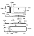
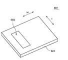
図1は、本発明の第1の実施形態による血圧測定用カフ(以下、「カフ」と略称する。)の展開状態の平面図(a)と、図1(a)の線A−A’に沿った断面図(b)である。 FIG. 1 is a plan view (a) of a developed state of a blood pressure measurement cuff (hereinafter abbreviated as “cuff”) according to a first embodiment of the present invention, and a line AA ′ in FIG. It is sectional drawing along (b).
カフ100は、細長く扁平な帯形状を有する。カフ100は、その長手方向にそって被測定部位を取り巻いて面ファスナ107と外布101Bとの係合により被測定部位に装着される。ここで、被測定部位は、例えば、ヒトの上腕部であるが、被測定部位はこれに限定されない。
The
外布101A,101Bは、カフ100が被測定部位を取り巻いたときに外側になる外装部材である。外側になる外装部材は、外布101Aおよび外布101Bの2つの部材からなり、縫合100sにより1つになっている。ただし、本発明において、上記の外側になる外装部材は、もとより外布101Aと外布101Bとを縫製したときに形作られる形状を有する単一の部材であってもよい。その場合、縫合100sを省略することができる。また、外布101Bには、空気を給排気する手段としてニップル110が配置されている。
The
断面図(b)を参照すれば、外布101A,101Bの片面には、それぞれ、気密性シート部材102が取り付けられ、一体化されている。ここでは、外布101A,101Bそれぞれに気密性シート102が取り付けられたものを、外側部材103A,103Bと称する。
Referring to the cross-sectional view (b), an
内布105は、被測定部位を取り巻いたときに内側(被測定部位側)になる外装部材である。内布105には、外布101A,101Bと係合する面ファスナ107が取り付けられている。内布105の面ファスナ107と反対側の面には、気密性シート部材104が取り付けられ、一体化されている。ここでは、内布105に気密性シート104が取り付けられたものを、内側部材106と称する。
The
外側部材103Bの気密性シート102および内側部材106の気密性シート104は、周縁溶着部100wおよび中間溶着部100waにおいて溶着されることで接合されており、空気袋111を形成している。
The
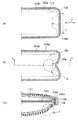
空気袋111内には、自然状態において被測定部位に沿うように湾曲しかつ可撓性を有するカーラ109が内包される。本実施形態によるカフ100においては、カーラ109の周方向H(被測定部位を取り巻く方向)の長さは、空気袋111の周方向Hに関する長さとほぼ一致する程度の寸法である。これは、たとえば、ユーザがカフ100を取り回す際に空気袋111内においてカーラ109が動き回ることを防止する点で好都合である。また、カーラ109は、その周方向Hの端部(周端(図1(a)におけるカーラ109の右端))において、周方向Hに対して略垂直な幅方向Iの中央部がその幅方向両側に存するコーナ部よりも前記周方向に関して後退した凹部109hを有する。凹部109hの効果については、後で詳述する。
The
図2は、カフ100を被測定部位Bに巻き回して固定し、空気袋111に空気を注入した状態での、カフ100の断面図である。このように、カフ100においては、空気袋111に空気を供給すると、空気袋111がカーラ109から遠ざかる方向に変形・変位する。そのため、矢印Pが指すように、カフ100の膨縮時に、カーラ109が空気袋111によって強く押さえつけられることがない。したがって、空気袋111の膨縮に伴い両者が接するようになろうとも、接点において作用する力は極めて小さく維持される。よって、カーラ109と空気袋111との間に大きなずれ応力が生じて、該応力が両者間の最大静止摩擦力を上回るまでの相当な期間、両者間の相対的位置関係の変化および両者の変形が阻害され、その後に大きなずれ運動が生じるような事態が発生することがない。また、空気袋111を構成する気密性シート102,104はそれぞれ、外布101A,101Bおよび内布105と一体的に変形・変位するため、膨縮時に、三者間の位置関係がずれることがない。よって、本血圧測定用カフでは、血圧測定の妨げとなるような膨縮時の雑音の発生は抑制される。
FIG. 2 is a cross-sectional view of the
図3は、外側部材103A,103Bの平面図((a))および立面図((b))である。外側部材103A,103Bは、外布101A,101Bに、気密性シート102を取り付けることにより形成されている。外布101A,101Bは、ポリエステルまたはナイロン製の起毛生地である。また、その他の素材を用いても外布101A,101Bを形成することは可能である。
FIG. 3 is a plan view ((a)) and an elevation view ((b)) of the
気密性シート102は、ポリ塩化ビニル(PVC)製のシート部材である。また、その他の素材を用いても気密性シート102を形成することは可能である。外布101A,101Bに気密性シート102を取り付けるには、外布101A,101BにPVCをラミネート加工するか、溶融状態のPVCを外布101A,101Bに適切に塗布すればよい。あるいは、シート状のPVC、すなわち気密性シート102そのものを、接着剤を用いて外布101A,101Bに貼り付けてもよい。本発明において、気密性シート102を外布101A,101Bに取り付ける方法に一切の限定はない。
The
図4は、内側部材106の平面図((a))および立面図((b))である。内側部材106は、内布105に、気密性シート104を取り付けることにより形成されている。内布105は、外布101A,101Bと同様、ポリエステルまたはナイロン製の生地である。また、その他の素材を用いても内布105を形成することは可能である。内布105は、外布101A,101Bよりも、伸縮性に富むことが望まれる。外布101A,101Bおよび内布105の伸縮性は、素材の選択によらずとも、織り方の選択により調整することができる。
FIG. 4 is a plan view ((a)) and an elevation view ((b)) of the
内側部材106においても、外側部材103A,103Bと同様、気密性シート104は、ポリ塩化ビニル(PVC)製のシート部材である。また、その他の素材を用いても気密性シート104を形成することは可能である。内布105に気密性シート104を取り付けるには、内布105にPVCをラミネート加工するか、溶融状態のPVCを内布105に塗布すればよい。あるいは、シート状のPVC、すなわち気密性シート104そのものを、接着剤を用いて内布105に貼り付けてもよい。本発明において、気密性シート104を内布105に取り付ける方法に一切の限定はない。
Also in the
図5Aは、カーラ109の斜視図である。カーラ109は、自然状態において、被測定部位を取り巻く方向に沿って(周方向Hに沿って)湾曲した形状を有する、可撓性の部材である。また、カーラ109は、周方向Hに関する端部(周端)において、中央部に、コーナ部よりも周方向Hに後退した凹部109hを有する。
FIG. 5A is a perspective view of the
図5Bおよび図5Cは、カーラ109の周方向Hの長さと、想定される被測定部位Bとの関係を示す図である。カーラ109は、図5Bに示されるように、被測定部位Bの周長よりも短くてよい。ただし、カーラ109は、被測定部位Bの周長の半分よりも長い周方向Hに関する長さを有することが望まれる。また、カーラ109は、図5Cに示されるように、想定される被測定部位Bの周長よりも長くともよい。
5B and 5C are diagrams illustrating the relationship between the length in the circumferential direction H of the
図6は、カーラ109の凹部109hの作用を説明する図である。図6(a)は、空気袋111に空気が存在しないときの、周端部近傍平面図である。図6(b)は、空気袋111に空気が供給されたときの、周端部近傍平面図であり、図6(c)は、図6(b)の線A−A'に沿った断面図である。
FIG. 6 is a diagram for explaining the operation of the
空気袋111に空気が供給されると、空気袋111は膨張を始める。そのとき、空気袋111は、凹部109hの近傍においては凹部109hに向かって自由に変形することができる。そのため、領域Rにおいて、空気袋111は、被測定部位に向かって大きく膨張することができる。
When air is supplied to the
このように、カーラ109の少なくとも1つの周端において、凹部109hを設けることにより、空気袋111の周端近傍においても、被測定部位を圧迫する力を十分に確保することができる。
As described above, by providing the
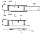
次に、図7、ならびに、図8Aないし図8Hを参照し、カフ100を製造する方法について説明する。図7は、カフ100の製造工程のフローチャートであり、図8Aないし図8Hは、製造工程の各段階における各部材の状態を示す模式図である。
Next, a method for manufacturing the
先ず、ステップS101において、気密性シート部材102が取り付けられた外布101Aすなわち外側部材103A、気密性シート部材102およびニップル110が取り付けられた外側部材103B、気密性シート部材104が取り付けられた内布105すなわち内側部材106を用意する(図8A)。
First, in step S101, the
次に、ステップS102において、外側部材103A,103Bの気密性シート部材102と、内側部材106の気密性シート部材104とを溶着し(周縁溶着部100w(図8B))、開口部を有する袋形状部(空気袋)を形成する(図8B)。
Next, in step S102, the
次に、ステップS103において、抜き型で余分な部材をカットし、カフを整形する(図8C)。 Next, in step S103, excess members are cut with a punching die, and the cuff is shaped (FIG. 8C).
次に、ステップS104において、溶着されなかった部分(開口部100x(図8D))を通して、平板形状のカーラ挿入用補助プレート5を空気袋111に挿入する(図8D)。
Next, in step S104, the flat plate-shaped curler insertion
次に、ステップS105において、カーラ109をカーラ挿入用補助プレート5に押しつけて略平板状に弾性変形させながらプレート5上を滑らせて開口部100xから空気袋111に挿入する(図8E)。
Next, in step S105, the
次に、ステップS106において、カーラ挿入用補助プレート5を空気袋111から取り出す(図8F)。
Next, in step S106, the curler insertion
なお、ステップS104、ステップS105、ステップS106に代えて、2枚のカーラ挿入用補助プレートを用意し、カーラ109を略平板状に弾性変形させて2枚のプレートに挟んだ状態で、それらを開口部100xから空気袋111に挿入し、そのあとで、2枚のプレートのみを空気袋111から抜き取ってもよい。
In place of step S104, step S105, and step S106, two curler insertion auxiliary plates are prepared, and the
次に、ステップS107において、ステップS102において溶着されなかった部分(開口部100x)において、外側部材103A,103Bの気密性シート部材102と、内側部材106の気密性シート部材104とを溶着し(中間溶着部100wa(図8G))、開口部100xを閉じて完全な空気袋111を形成する(図8G)。
Next, in step S107, the
最後に、ステップS108において、面ファスナ107の取り付け等の縫製加工を行う(図8H)。
Finally, in step S108, a sewing process such as attaching the
以上のように、本製造方法によれば、極めて容易に、カフ100を製造することが可能である。本方法では、カフ100の外周部分において外布101A,101Bと内布105とを縫製して袋状の外装カバーを形成する必要がないため、製造コストを低減することが可能となる。
As described above, according to this manufacturing method, the
次に、本発明の第2の実施形態によるカフ200について説明する。図9は、本発明の第2の実施形態によるカフ200の展開状態の平面図(a)と、図9(a)の線A−A’に沿った断面図(b)である。以下の説明では、先の実施形態と同様の構成については、適宜説明を省略する。
Next, a
本実施形態によるカフ200においては、気密性シート部材102と気密性シート部材104とは、中間溶着部200waおよび周縁溶着部100wにおいて溶着されて空気袋111を形成している。カフ200では、空気袋111の周方向Hに関する長さ(中間溶着部200waから図中右端の周縁溶着部100wまでの周方向Hに沿った長さ)が、カーラ109の周方向Hの長さよりも長くなっている。これはすなわち、空気袋111の周方向Hの長さを、カーラ209の周方向Hの長さと無関係に設計することができることを意味する。これに伴い、本実施形態によるカフ200においては、たとえば、ユーザがカフ200を取り回す際に空気袋111内においてカーラ209が動き回ることを防止するために、カーラ209と空気袋111との相対的位置関係を固定する位置決め部を備えている。
In the
カフ200は、カーラ209と空気袋111との相対的位置関係を固定する位置決め部として、カーラ209の外面に形成され、ニップル110の内部にはまり込む突起部209pを備えている。
The
図10は、カーラ209の斜視図である。カーラ209は、その外面の、空気袋111内に配置されたときにニップル110に対応する位置に、ニップル110の内部にはまり込む突起部209pを備える。突起部209pの作用により、カーラ209は空気袋111内で位置が固定される。
FIG. 10 is a perspective view of the
図11は、突起部209pの断面形状を示す図である。図11(a)に示される例では、突起部209pの断面形状は、O字型をしており、O字の内部は、空気の流通が可能な空洞である。図11(b)に示される例では、突起部209p1の断面形状は、U字型をしている。突起部209pの断面形状は、これらに限定されず、その他の形状であってもよい。
FIG. 11 is a diagram showing a cross-sectional shape of the
このように、第2の実施形態によるカフ200においては、カーラ209を空気袋111内にて位置決めする手段が配されている。これにより、空気袋111の周方向Hの長さを、カーラ209の周方向Hの長さによらずに自由に設計することができ、かつカーラ209が空気袋111内で不要に動き回ることが防止される。
As described above, in the
次に、図12、ならびに、図13Aないし図13Hを参照し、カフ200を製造する方法について説明する。図12は、カフ200の製造工程のフローチャートであり、図13Aないし図13Hは、製造工程の各段階における各部材の状態を示す模式図である。
Next, a method for manufacturing the
先ず、ステップS201において、気密性シート部材102が取り付けられた外布101Aすなわち外側部材103A、気密性シート部材102およびニップル110が取り付けられた外側部材103B、気密性シート部材104が取り付けられた内布105すなわち内側部材106を用意する(図13A)。
First, in step S201, the
次に、ステップS202において、外側部材103A,103Bの気密性シート部材102と、内側部材106の気密性シート部材104とを溶着し(周縁溶着部100w(図13B))、開口部を有する袋形状部(空気袋)を形成する(図13B)。
Next, in step S202, the
次に、ステップS203において、抜き型で余分な部材をカットし、カフを整形する(図13C)。 Next, in step S203, excess members are cut with a punching die, and the cuff is shaped (FIG. 13C).
次に、ステップS204において、溶着されなかった部分(開口部200x(図13D))を通して、平板形状のカーラ挿入用補助プレート5を空気袋111に挿入する(図13D)。
Next, in step S204, the flat plate-shaped curler insertion
次に、ステップS205において、その外面に突起部209pを備えたカーラ209をカーラ挿入用補助プレート5に押しつけて略平板状に弾性変形させながらプレート5上を滑らせて開口部200xから空気袋111に挿入する(図13E)。
Next, in step S205, the
次に、ステップS206において、カーラ挿入用補助プレート5を空気袋111から取り出す(図13F)。
Next, in step S206, the curler insertion
なお、ステップS204、ステップS205、ステップS206に代えて、2枚のカーラ挿入用補助プレートを用意し、カーラ209を略平板状に弾性変形させて2枚のプレートに挟んだ状態で、それらを開口部200xから空気袋111に挿入し、そのあとで、2枚のプレートのみを空気袋111から抜き取ってもよい。
In place of step S204, step S205, and step S206, two curler insertion auxiliary plates are prepared, and the
次に、ステップS207において、カーラ209の突起部209pを、ニップル110の内部にはめ込む(図13F)。
Next, in step S207, the
次に、ステップS208において、ステップS202において溶着されなかった部分(開口部200x)において、外側部材103A,103Bの気密性シート部材102と、内側部材106の気密性シート部材104とを溶着し(中間溶着部200wa(図13G))、開口部200xを閉じて完全な空気袋111を形成する(図13G)。
Next, in step S208, the
最後に、ステップS209において、面ファスナ107の取り付け等の縫製加工を行う(図13H)。
Finally, in step S209, a sewing process such as attaching the
以上のように、本製造方法によれば、極めて容易に、カフ200を製造することが可能である。本方法では、カフ200の外周部分において外布101A,101Bと内布105とを縫製して袋状の外装カバーを形成する必要がないため、製造コストを低減することが可能となる。
As described above, according to this manufacturing method, the
次に、本発明の第3の実施形態によるカフ300について説明する。図14は、本発明の第3の実施形態によるカフ300の展開状態の平面図(a)と、図14(a)の線A−A’に沿った断面図(b)である。以下の説明では、先の実施形態と同様の構成については、適宜説明を省略する。
Next, a
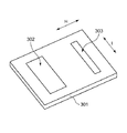
本実施形態によるカフ300は、先の実施形態によるカフと同様、気密性シート部材102と気密性シート部材104とは、中間溶着部200waおよび周縁溶着部100wにおいて溶着され空気袋111を形成している。カフ300では、カフ200と同様、空気袋111の周方向Hの長さを、カーラ109の周方向Hの長さと無関係に設計することができる。これに伴い、本実施形態によるカフ300においては、位置決め部として、カーラ固定用シート部材301を有している。カーラ固定用シート部材301は、空気袋111の内面とカーラ109とに取り付けられ、カーラ109を空気袋111に対し位置決めする。カーラ固定用シート部材301と空気袋111の内面との固定は、両面粘着性テープ302によりなされている。カーラ固定用シート部材301とカーラ109との固定もまた、両面粘着性テープ303によりなされている。なお、カフ300においては、第2の実施形態におけるカーラ209のように、カーラ109の外面に突起部を備える必要はない。
In the
図15は、カーラ固定用シート部材301の斜視図である。カーラ固定用シート部材301は、たとえば、PVCシートである。カーラ固定用シート部材301には、その上面に、両面粘着性テープ302,303が貼り付けられている。
FIG. 15 is a perspective view of the curler fixing
このように、第3の実施形態によるカフ300においては、カーラ109を空気袋111内にて位置決めする手段が配されている。これにより、空気袋111の周方向Hの長さを、カーラ109の周方向Hの長さによらずに自由に設計することができ、かつカーラ109が空気袋111内で不要に動き回ることが防止される。
As described above, in the
次に、図16、ならびに、図17Aないし図17Iを参照し、カフ300を製造する方法について説明する。図16は、カフ300の製造工程のフローチャートであり、図17Aないし図17Iは、製造工程の各段階における各部材の状態を示す模式図である。
Next, a method for manufacturing the
先ず、ステップS301において、気密性シート部材102が取り付けられた外布101Aすなわち外側部材103A、気密性シート部材102およびニップル110が取り付けられた外側部材103B、気密性シート部材104が取り付けられた内布105すなわち内側部材106を用意する(図17A)。
First, in step S301, the
次に、ステップS302において、外側部材103A,103Bの気密性シート部材102と、内側部材106の気密性シート部材104とを溶着し(周縁溶着部100w(図17B))、開口部を有する袋形状部(空気袋)を形成する(図17B)。
Next, in step S302, the
次に、ステップS303において、抜き型で余分な部材をカットし、カフを整形する(図17C)。 Next, in step S303, excess members are cut with a punching die, and the cuff is shaped (FIG. 17C).
次に、ステップS304において、溶着されなかった部分(開口部300x(図17F))を通して、平板形状のカーラ挿入用補助プレート5を空気袋111に挿入する(図17D)。
Next, in step S304, the flat plate-shaped curler insertion
次に、ステップS305において、両面粘着性テープ303を用いてカーラ109にカーラ固定用シート部材301を取り付ける(図17E)。
Next, in step S305, the curler fixing
次に、ステップS306において、カーラ固定用シート部材301が取り付けられたカーラ109をカーラ挿入用補助プレート5に押しつけて略平板状に弾性変形させながらプレート5上を滑らせて開口部300xから空気袋111に挿入する(図17F)。
Next, in step S306, the
次に、ステップS307において、カーラ挿入用補助プレート5を空気袋111から取り出す(図17G)。
Next, in step S307, the curler insertion
なお、ステップS304、ステップS306、ステップS307に代えて、2枚のカーラ挿入用補助プレートを用意し、カーラ109を略平板状に弾性変形させて2枚のプレートに挟んだ状態で、それらを開口部300xから空気袋111に挿入し、そのあとで、2枚のプレートのみを空気袋111から抜き取ってもよい。
Instead of Step S304, Step S306, and Step S307, two curler insertion auxiliary plates are prepared, and the
次に、ステップS308において、両面粘着性テープ302を用いて空気袋111の内面にカーラ固定用シート部材301を取り付ける(図17G)。
Next, in step S308, the curler fixing
次に、ステップS309において、ステップS302において溶着されなかった部分(開口部300x)において、外側部材103A,103Bの気密性シート部材102と、内側部材106の気密性シート部材104とを溶着し(中間溶着部200wa(図17H))、開口部300xを閉じて完全な空気袋111を形成する(図17H)。
Next, in step S309, the
最後に、ステップS310において、面ファスナ107の取り付け等の縫製加工を行う(図17I)。
Finally, in step S310, a sewing process such as attaching the
以上のように、本製造方法によれば、極めて容易に、カフ300を製造することが可能である。本方法では、カフ300の外周部分において外布101A,101Bと内布105とを縫製して袋状の外装カバーを形成する必要がないため、製造コストを低減することが可能となる。
As described above, according to the present manufacturing method, the
次に、本発明の第4の実施形態によるカフ400について説明する。図18は、本発明の第4の実施形態によるカフ400の展開状態の平面図(a)と、図18(a)の線A−A’に沿った断面図(b)である。以下の説明では、先の実施形態と同様の構成については、適宜説明を省略する。
Next, a
本実施形態によるカフ400においては、先の実施形態によるカフと同様、気密性シート部材102と気密性シート部材104とは、中間溶着部200waおよび周縁溶着部100wにおいて溶着され空気袋111を形成している。カフ400では、カフ200,300と同様、空気袋111の周方向Hの長さを、カーラ109の周方向Hの長さと無関係に設計することができる。それに伴い、本実施形態によるカフ400においては、位置決め部として、カーラ固定用シート部材401を有している。カーラ固定用シート部材401は、空気袋111の周方向Hの周縁部(周縁溶着部100wb)において、気密性シート部材102と気密性シート部材104に挟まれて溶着されることにより空気袋111に取り付けられ、両面粘着性テープ402によってカーラ109に取り付けられることにより、カーラ109を空気袋111に対し位置決めする。なお、カフ400においては、カフ300と同様、第2の実施形態におけるカーラ209のように、カーラ109の外面に突起部を備える必要はない。
In the
図19は、カーラ固定用シート部材401の斜視図である。カーラ固定用シート部材401は、たとえば、PVCシートである。カーラ固定用シート部材401には、その上面に、両面粘着性テープ402が貼り付けられている。
FIG. 19 is a perspective view of the curler fixing
このように、第4の実施形態によるカフ400においては、カーラ109を空気袋111内にて位置決めする手段が配されている。これにより、空気袋111の周方向Hの長さを、カーラ109の周方向Hの長さによらずに自由に設計することができ、かつカーラ109が空気袋111内で不要に動き回ることが防止される。
Thus, in the
次に、図20、ならびに、図21Aないし図21Gを参照し、カフ400を製造する方法について説明する。図20は、カフ400の製造工程のフローチャートであり、図21Aないし図21Gは、製造工程の各段階における各部材の状態を示す模式図である。
Next, a method for manufacturing the
先ず、ステップS401において、気密性シート部材102が取り付けられた外布101Aすなわち外側部材103A、気密性シート部材102およびニップル110が取り付けられた外側部材103B、気密性シート部材104が取り付けられた内布105すなわち内側部材106、両面粘着性テープ402が取り付けられたカーラ固定用シート部材401を用意する(図21A)。
First, in step S401, the
次に、ステップS402において、外側部材103A,103Bの気密性シート部材102と、内側部材106の気密性シート部材104とを、カフ(空気袋111)の周方向縁部においてカーラ固定用シート部材401を挟んで溶着し(周縁溶着部100w、中間溶着部200wa、周縁溶着部100wb(図21B))、開口部を有する袋形状部(空気袋)を形成する(図21B)。本工程においては、開口部(400x(図21D))は、カフ400の周端部(図21Bのカフにおける右側の端部)に設けられる。
Next, in step S402, the
次に、ステップS403において、抜き型で余分な部材をカットし、カフを整形する(図21C)。 Next, in step S403, excess members are cut with a punching die, and the cuff is shaped (FIG. 21C).
次に、ステップS404において、溶着されなかった部分(開口部400x(図21D))を通して、平板形状のカーラ挿入用補助プレート5を空気袋111に挿入する(図21D)。
Next, in step S404, the flat plate-shaped curler insertion
次に、ステップS405において、カーラ109をカーラ挿入用補助プレート5に押しつけて略平板状に弾性変形させながらプレート5上を滑らせて開口部400xから空気袋111に挿入する(図21D)。
Next, in step S405, the
次に、ステップS406において、カーラ挿入用補助プレート5を空気袋111から取り出す(図21E)。
Next, in step S406, the curler insertion
なお、ステップS404、ステップS405、ステップS406に代えて、2枚のカーラ挿入用補助プレートを用意し、カーラ109を略平板状に弾性変形させて2枚のプレートに挟んだ状態で、それらを開口部400xから空気袋111に挿入し、そのあとで、2枚のプレートのみを空気袋111から抜き取ってもよい。
Instead of Step S404, Step S405, and Step S406, two curler insertion auxiliary plates are prepared, and the
次に、ステップS407において、両面粘着性テープ402を用いてカーラ固定用シート部材401にカーラ109を取り付ける(図21E)。
Next, in step S407, the
次に、ステップS408において、ステップS402において溶着されなかった部分(開口部400x(図21D))において、外側部材103Bの気密性シート部材102と、内側部材106の気密性シート部材104とを溶着し、開口部400xを閉じて完全な空気袋111を形成する(図21F)。
Next, in step S408, in the portion which has not been welded in the step S402 (
最後に、ステップS409において、面ファスナ107の取り付け等の縫製加工を行う(図21G)。
Finally, in step S409, a sewing process such as attaching the
以上のように、本製造方法によれば、極めて容易に、カフ400を製造することが可能である。本方法では、カフ400の外周部分において外布101A,101Bと内布105とを縫製して袋状の外装カバーを形成する必要がないため、製造コストを低減することが可能となる。
As described above, according to the present manufacturing method, the
次に、本発明の第5の実施形態によるカフ500について説明する。図22は、本発明の第5の実施形態によるカフ500の展開状態の平面図(a)と、図22(a)の線A−A’に沿った断面図(b)である。以下の説明では、先の実施形態と同様の構成については、適宜説明を省略する。
Next, a
本実施形態によるカフ500においては、先の実施形態によるカフと同様、気密性シート部材102と気密性シート部材104とは、中間溶着部200waおよび周縁溶着部100wにおいて溶着され空気袋111を形成している。カフ500では、カフ400等と同様、空気袋111の周方向Hの長さを、カーラ109の周方向Hの長さと無関係に設計することができる。そのために、本実施形態によるカフ500においては、位置決め部として、カーラ固定用シート部材401を有している。カーラ固定用シート部材401は、第4の実施形態によるカフ400とは異なり、中央溶着部200waの近傍の空気袋111の周方向Hの周縁部において、気密性シート部材102と気密性シート部材104に挟まれて溶着される(周縁溶着部100wb)ことにより空気袋111に取り付けられ、両面粘着性テープ402によってカーラ109に取り付けられることにより、カーラ109を空気袋111に対し位置決めする。なお、カフ500においては、カフ400と同様、第2の実施形態におけるカーラ209のように、カーラ109の外面に突起部を備える必要はない。
In the
このように、第5の実施形態によるカフ500においては、カーラ109を空気袋111内にて位置決めする手段が配されている。これにより、空気袋111の周方向Hの長さを、カーラ109の周方向Hの長さによらずに自由に設計することができ、かつカーラ109が空気袋111内で不要に動き回ることが防止される。
Thus, in the
次に、図23、ならびに、図24Aないし図24Hを参照し、カフ500を製造する方法について説明する。図23は、カフ500の製造工程のフローチャートであり、図24Aないし図24Hは、製造工程の各段階における各部材の状態を示す模式図である。
Next, a method for manufacturing the
先ず、ステップS501において、気密性シート部材102が取り付けられた外布101Aすなわち外側部材103A、気密性シート部材102およびニップル110が取り付けられた外側部材103B、気密性シート部材104が取り付けられた内布105すなわち内側部材106、両面粘着性テープ402が取り付けられたカーラ固定用シート部材401を用意する(図24A)。
First, in step S501, the
次に、ステップS502において、外側部材103A,103Bの気密性シート部材102と、内側部材106の気密性シート部材104とを、カフ(空気袋111)の周縁部の周方向中央部分でカーラ固定用シート部材401を挟んで溶着し(周縁溶着部100wb(図24B))、開口部を有する袋形状部(空気袋)を形成する(図24B)。本工程においては、開口部(500x(図24D))は、カフ500の中央部(外側部材103Aと外側部材103Bの接続部分)に設けられる。
Next, in step S502, the
次に、ステップS503において、抜き型で余分な部材をカットし、カフを整形する(図24C)。 Next, in step S503, excess members are cut with a punching die, and the cuff is shaped (FIG. 24C).
次に、ステップS504において、溶着されなかった部分(開口部500x)を通して、平板形状のカーラ挿入用補助プレート5を空気袋111に挿入する(図24D)。
Next, in step S504, the flat plate-shaped curler insertion
次に、ステップS505において、カーラ109をカーラ挿入用補助プレート5に押しつけて略平板状に弾性変形させながらプレート5上を滑らせて開口部500xから空気袋111に挿入する(図24E)。
Next, in step S505, the
次に、ステップS506において、カーラ挿入用補助プレート5を空気袋111から取り出す(図24F)。
Next, in step S506, the curler insertion
なお、ステップS504、ステップS505、ステップS506に代えて、2枚のカーラ挿入用補助プレートを用意し、カーラ109を略平板状に弾性変形させて2枚のプレートに挟んだ状態で、それらを開口部500xから空気袋111に挿入し、そのあとで、2枚のプレートのみを空気袋111から抜き取ってもよい。
Instead of Step S504, Step S505, and Step S506, two curler insertion auxiliary plates are prepared, and the
次に、ステップS507において、両面粘着性テープ402を用いてカーラ固定用シート部材401にカーラ109を取り付ける(図24F)。
Next, in step S507, the
次に、ステップS508において、ステップS402において溶着されなかった部分(開口部500x)において、外側部材103A,103Bの気密性シート部材102と、内側部材106の気密性シート部材104とを溶着し、開口部500xを閉じて完全な空気袋111を形成する(図24G)。
Next, in step S508, the
最後に、ステップS509において、面ファスナ107の取り付け等の縫製加工を行う(図24H)。
Finally, in step S509 , a sewing process such as attaching the
以上のように、本製造方法によれば、極めて容易に、カフ500を製造することが可能である。本方法では、カフ500の外周部分において外布101A,101Bと内布105とを縫製して袋状の外装カバーを形成する必要がないため、製造コストを低減することが可能となる。
As described above, according to the present manufacturing method, the
次に、本発明の第6の実施形態によるカフ600について説明する。図25は、本発明の第6の実施形態によるカフ600の展開状態の平面図(a)と、図25(a)の線A−A’に沿った断面図(b)である。以下の説明では、先の実施形態と同様の構成については、適宜説明を省略する。
Next, a
本実施形態によるカフ600においては、先の実施形態によるカフと同様、気密性シート部材102と気密性シート部材104とは、中間溶着部200waおよび周縁溶着部100wにおいて溶着され空気袋111を形成している。カフ600では、カフ500等と同様、空気袋111の周方向Hの長さを、カーラ109の周方向Hの長さと無関係に設計することができる。これに伴い、本実施形態によるカフ600においては、位置決め部として、カーラ固定用シート部材601を有している。カーラ固定用シート部材601は、空気袋111の周方向Hに略垂直な幅方向Iの周縁部において、気密性シート部材102と気密性シート部材104に挟まれて溶着される(周縁溶着部100wc)ことにより空気袋111に取り付けられ、両面粘着性テープ602によってカーラ109に取り付けられることにより、カーラ109を空気袋111に対し位置決めする。なお、カフ600においては、カフ500等と同様、第2の実施形態におけるカーラ209のように、カーラ109の外面に突起部を備える必要はない。
In the
図26は、カーラ固定用シート部材601の斜視図である。カーラ固定用シート部材601は、たとえば、PVCシートである。カーラ固定用シート部材601には、その上面に、両面粘着性テープ602が貼り付けられている。
FIG. 26 is a perspective view of the curler fixing
このように、第6の実施形態によるカフ600においては、カーラ109を空気袋111内にて位置決めする手段が配されている。これにより、空気袋111の周方向Hの長さを、カーラ109の周方向Hの長さによらずに自由に設計することができ、かつカーラ109が空気袋111内で不要に動き回ることが防止される。
Thus, in the
次に、図27、ならびに、図28Aないし図28Jを参照し、カフ600を製造する方法について説明する。図27は、カフ600の製造工程のフローチャートであり、図28Aないし図28Jは、製造工程の各段階における各部材の状態を示す模式図である。
Next, a method for manufacturing the
先ず、ステップS601において、気密性シート部材102が取り付けられた外布101Aすなわち外側部材103A、気密性シート部材102およびニップル110が取り付けられた外側部材103B、気密性シート部材104が取り付けられた内布105すなわち内側部材106を用意する(図28A)。
First, in step S601, the
次に、ステップS602において、外側部材103A,103Bの気密性シート部材102と、内側部材106の気密性シート部材104とを溶着し(周縁溶着部100w)、開口部を有する袋形状部(空気袋)を形成する(図28B)。本工程においては、開口部(600x(図28F))は、カフ600の周端部(図28Bのカフにおける右側の端部)に設けられる。
Next, in step S602, the
次に、ステップS603において、抜き型で余分な部材をカットし、カフを整形する(図28C)。 Next, in step S603, excess members are cut with a punching die, and the cuff is shaped (FIG. 28C).
次に、ステップS604において、溶着されなかった部分(開口部600x)を通して、平板形状のカーラ挿入用補助プレート5を空気袋111に挿入する(図28D)。
Next, in step S604, the flat plate-shaped curler insertion
次に、ステップS605において、両面粘着性テープ602を用いてカーラ109にカーラ固定用シート部材601を取り付ける(図28E)。
Next, in step S605, the curler fixing
次に、ステップS606において、カーラ固定用シート部材601が取り付けられたカーラ109をカーラ挿入用補助プレート5に押しつけて略平板状に弾性変形させながらプレート5上を滑らせて開口部600x(図28F)から空気袋111に挿入する(図28F)。
Next, in step S606, the
次に、ステップS607において、カーラ挿入用補助プレート5を空気袋111から取り出す(図28G)。
Next, in step S607, the curler insertion
なお、ステップS604、ステップS606、ステップS607に代えて、2枚のカーラ挿入用補助プレートを用意し、カーラ109を略平板状に弾性変形させて2枚のプレートに挟んだ状態で、それらを開口部600xから空気袋111に挿入し、そのあとで、2枚のプレートのみを空気袋111から抜き取ってもよい。
Instead of Step S604, Step S606, and Step S607, two curler insertion auxiliary plates are prepared, and the
次に、ステップS608において、ステップS602において溶着されなかった部分(開口部600x)において、外側部材103Bの気密性シート部材102と、内側部材106の気密性シート部材104とをカーラ固定用シート部材601を挟んで溶着し(周縁溶着部100wc(図25))、開口部600xを閉じて完全な空気袋111を形成する(図28H)。次に、余分な部材(カーラ固定用シート部材601のうち周縁溶着部100wcを超えて空気袋111の外側に出ている部分)をカットし、カフを整形する(図28I)。
Next, in step S608, the in part has not been welded in the step S602 (
最後に、ステップS609において、面ファスナ107の取り付け等の縫製加工を行う(図28J)。
Finally, in step S609, a sewing process such as attaching the
以上のように、本製造方法によれば、極めて容易に、カフ600を製造することが可能である。本方法では、カフ600の外周部分において外布101A,101Bと内布105とを縫製して袋状の外装カバーを形成する必要がないため、製造コストを低減することが可能となる。
As described above, according to this manufacturing method, the
5: カーラ挿入用補助プレート
100: 血圧測定用カフ
100s: 縫合部
100w: 周縁溶着部
100wa: 中間溶着部
100wb: 周縁溶着部
100wc: 周縁溶着部
100x: 開口部
101A,101B: 外布
102: 気密性シート
103A,103B: 外側部材
104: 気密性シート
105: 内布
106: 内側部材
107: 面ファスナ
109: カーラ
109h: 凹部
110: ニップル
111: 空気袋
200: 血圧測定用カフ
200wa: 中間溶着部
200x: 開口部
209: カーラ
209p: 突起部
300: 血圧測定用カフ
301: カーラ固定溶シート部材
302,303: 両面粘着性テープ
300x: 開口部
400: 血圧測定用カフ
401: カーラ固定溶シート部材
402: 両面粘着性テープ
400x: 開口部
500: 血圧測定用カフ
500x: 開口部
600: 血圧測定用カフ
601: カーラ固定溶シート部材
602: 両面粘着性テープ
600x: 開口部
5: Curler insertion auxiliary plate 100: Blood
Claims (16)
自然状態において前記被測定部位に沿うように湾曲し可撓性をもつカーラと、
前記カーラの内側と外側を取り巻いて前記カーラを内包する空気袋と、
前記空気袋の前記被測定部位側の外面に付けられた内布と、
前記空気袋の前記被測定部位と反対側の外面に付けられた外布と、
を有する血圧測定用カフ。 A blood pressure measurement cuff attached to surround the measurement site,
A curler that is curved and flexible so as to follow the measurement site in a natural state;
An air bag surrounding the inside and outside of the curler and enclosing the curler;
An inner cloth attached to an outer surface of the air bag on the measurement site side;
An outer cloth attached to the outer surface of the air bag opposite to the measurement site;
A blood pressure measurement cuff.
前記位置決め部は、前記カーラの外面に形成され、前記ニップルの内部にはまり込む突起部である、請求項4に記載の血圧測定用カフ。 Furthermore, it has a nipple for supplying and exhausting air,
The blood pressure measurement cuff according to claim 4, wherein the positioning portion is a protrusion formed on an outer surface of the curler and fitted into the nipple.
空気袋形成用の第1気密性シート部材が付けられた外布と、空気袋形成用の第2気密性シート部材が付けられた内布と、を用意するステップと、
前記第1気密性シート部材と前記第2気密性シート部材とを溶着して袋形状部を形成するステップを有し、前記袋形状部は、少なくとも周縁部の一部が開口部として開いており、
さらに、前記開口部を通して前記カーラを前記袋形状部に挿入するステップと、
前記袋形状部の前記開口部を溶着し、空気袋を形成するステップと、
を有する血圧測定用カフの製造方法。 A method for producing a blood pressure measurement cuff according to claim 1,
Providing an outer cloth provided with a first airtight sheet member for forming an air bag and an inner cloth provided with a second airtight sheet member for forming an air bag;
The first airtight sheet member and the second airtight sheet member are welded to form a bag-shaped portion, and at least a part of the peripheral edge portion of the bag-shaped portion is opened as an opening. ,
And inserting the curler into the bag-shaped portion through the opening;
Welding the opening of the bag-shaped portion to form an air bag;
A method for manufacturing a cuff for measuring blood pressure, comprising:
次に、前記カーラを、前記カーラ挿入用補助プレートに押しつけて略平板状に弾性変形させながら該プレート上を滑らせて前記開口部を通して前記袋形状部に挿入するサブステップと、
前記袋形状部内から前記開口部を通して前記カーラ挿入用補助プレートを取り出すサブステップと、を含んでいる、
請求項10に記載の血圧測定用カフの製造方法。 The step of inserting, first, a sub-step of inserting a flat plate-shaped curler insertion auxiliary plate into the bag-shaped portion through the opening,
Next, the curler is pressed against the curler insertion auxiliary plate and elastically deformed into a substantially flat plate shape, and is slid on the plate and inserted into the bag-shaped portion through the opening, and
A sub-step of taking out the curler insertion auxiliary plate from the bag-shaped portion through the opening,
The method for producing a blood pressure measurement cuff according to claim 10.
2枚の前記カーラ挿入用補助プレートを前記開口部を通して前記袋形状部内から取り出すサブステップと、を含んでいる、
請求項10に記載の血圧測定用カフの製造方法。 In the inserting step, first, the two curler insertion auxiliary plates and the curler are placed between the two flat curler insertion auxiliary plates while elastically deforming and sandwiching the curler into a substantially flat plate shape. A sub-step of inserting into the bag-shaped part through the opening;
Taking out the two curler insertion auxiliary plates from the bag-shaped portion through the opening, and
The method for producing a blood pressure measurement cuff according to claim 10.
請求項10から12までのいずれか1つに記載の血圧測定用カフの製造方法。 Furthermore, after the step of inserting the curler into the bag-shaped portion and before the step of forming the air bag, a nipple disposed on the outer cloth is provided with a protrusion formed on the outer surface of the curler. A step of fitting into the interior of the
The method for producing a blood pressure measurement cuff according to any one of claims 10 to 12.
さらに、カーラを前記袋形状部に挿入するステップの後で、かつ前記空気袋を形成するステップの前に、前記カーラを前記第3シート部材に取り付けるステップ、を有する、
請求項10から12までのいずれか1つに記載の血圧測定用カフの製造方法。 The step of forming the bag-shaped portion includes the first air-tight sheet member and the second air-tight sheet at a part of a peripheral edge portion in a longitudinal direction parallel to a circumferential direction surrounding the measurement site of the bag-shaped portion. The third sheet member is sandwiched between the members and welded,
A step of attaching the curler to the third sheet member after the step of inserting the curler into the bag-shaped portion and before the step of forming the air bag;
The method for producing a blood pressure measurement cuff according to any one of claims 10 to 12.
前記カーラを前記袋形状部に挿入するステップの後で、かつ前記空気袋を形成するステップの前に、前記第3シート部材を、前記袋形状部の内面に取り付けるステップと、を有する、
請求項10から12までにいずれか1つに記載の血圧測定用カフの製造方法。 A step of attaching a third sheet member to the curler before the step of inserting the curler into the bag-shaped portion;
Attaching the third sheet member to the inner surface of the bag-shaped portion after the step of inserting the curler into the bag-shaped portion and before the step of forming the air bag,
The method for producing a blood pressure measurement cuff according to any one of claims 10 to 12.
前記空気袋を形成するステップは、前記袋形状部の前記被測定部位を取り巻く周方向に対して略垂直な幅方向の一部において、前記第1気密性シート部材と前記第2気密性シート部材との間に前記第3シート部材を挟んで溶着する、
請求項10から12までのいずれか1つに記載の血圧測定用カフの製造方法。 Furthermore, before the step of inserting the curler into the bag-shaped portion, the step of attaching a third sheet member to the curler,
The step of forming the air bag includes the first airtight sheet member and the second airtight sheet member in a part of a width direction substantially perpendicular to a circumferential direction surrounding the measurement site of the bag-shaped portion. The third sheet member is sandwiched between and welded,
The method for producing a blood pressure measurement cuff according to any one of claims 10 to 12.
Priority Applications (7)
| Application Number | Priority Date | Filing Date | Title |
|---|---|---|---|
| JP2013045788A JP6051964B2 (en) | 2013-03-07 | 2013-03-07 | Blood pressure measurement cuff and method for manufacturing blood pressure measurement cuff |
| CN201480010800.XA CN105142507B (en) | 2013-03-07 | 2014-03-05 | Cuff for measuring blood pressure and the manufacture method of cuff for measuring blood pressure |
| PCT/JP2014/055567 WO2014136818A1 (en) | 2013-03-07 | 2014-03-05 | Blood pressure measurement cuff and production method for blood pressure measurement cuff |
| BR112015021361-8A BR112015021361B1 (en) | 2013-03-07 | 2014-03-05 | BLOOD PRESSURE MEASUREMENT CANDLE, AND, METHOD TO MANUFACTURE THE BLOOD PRESSURE MEASUREMENT CANDLE |
| DE112014001127.4T DE112014001127T5 (en) | 2013-03-07 | 2014-03-05 | Blood pressure cuff and method for establishing the blood pressure cuff |
| US14/818,961 US11478161B2 (en) | 2013-03-07 | 2015-08-05 | Blood pressure measurement cuff and method for manufacturing blood pressure measurement cuff |
| US15/930,763 US11596318B2 (en) | 2013-03-07 | 2020-05-13 | Blood pressure measurement cuff and method for manufacturing blood pressure measurement cuff |
Applications Claiming Priority (1)
| Application Number | Priority Date | Filing Date | Title |
|---|---|---|---|
| JP2013045788A JP6051964B2 (en) | 2013-03-07 | 2013-03-07 | Blood pressure measurement cuff and method for manufacturing blood pressure measurement cuff |
Publications (3)
| Publication Number | Publication Date |
|---|---|
| JP2014171606A JP2014171606A (en) | 2014-09-22 |
| JP2014171606A5 JP2014171606A5 (en) | 2016-04-14 |
| JP6051964B2 true JP6051964B2 (en) | 2016-12-27 |
Family
ID=51491330
Family Applications (1)
| Application Number | Title | Priority Date | Filing Date |
|---|---|---|---|
| JP2013045788A Active JP6051964B2 (en) | 2013-03-07 | 2013-03-07 | Blood pressure measurement cuff and method for manufacturing blood pressure measurement cuff |
Country Status (6)
| Country | Link |
|---|---|
| US (2) | US11478161B2 (en) |
| JP (1) | JP6051964B2 (en) |
| CN (1) | CN105142507B (en) |
| BR (1) | BR112015021361B1 (en) |
| DE (1) | DE112014001127T5 (en) |
| WO (1) | WO2014136818A1 (en) |
Families Citing this family (9)
| Publication number | Priority date | Publication date | Assignee | Title |
|---|---|---|---|---|
| JP6051964B2 (en) * | 2013-03-07 | 2016-12-27 | オムロンヘルスケア株式会社 | Blood pressure measurement cuff and method for manufacturing blood pressure measurement cuff |
| CN104434075B (en) * | 2014-12-24 | 2017-08-04 | 深圳瑞光康泰科技有限公司 | Air bag cuff and automated blood pressure device |
| CN105935292B (en) * | 2016-06-08 | 2018-12-28 | 东莞市鸿德医用塑料制品有限公司 | A kind of blood-pressure sleeve and its manufacturing method |
| CN106108873A (en) * | 2016-06-12 | 2016-11-16 | 江苏鱼跃医疗设备股份有限公司 | A kind of measurement blood pressure cuff |
| CN106441552B (en) * | 2016-09-21 | 2019-12-17 | 广州视源电子科技股份有限公司 | method and system for detecting noise of blood pressure cuff |
| JP7118852B2 (en) * | 2018-10-15 | 2022-08-16 | オムロン株式会社 | Blood pressure measuring device |
| JP7175738B2 (en) * | 2018-12-13 | 2022-11-21 | オムロン株式会社 | Blood pressure measuring device |
| JP7150595B2 (en) * | 2018-12-27 | 2022-10-11 | オムロンヘルスケア株式会社 | Cuff cover for blood pressure measuring device |
| JP6751462B1 (en) * | 2019-07-24 | 2020-09-02 | シチズン時計株式会社 | Blood pressure cuff |
Family Cites Families (21)
| Publication number | Priority date | Publication date | Assignee | Title |
|---|---|---|---|---|
| US3670735A (en) * | 1970-02-09 | 1972-06-20 | Walter & Kidde Co Inc | Disposable inflatable tourniquet |
| JPS59232531A (en) * | 1983-06-15 | 1984-12-27 | 松下電工株式会社 | Hemomanometer |
| US5411518A (en) * | 1994-05-24 | 1995-05-02 | Design +3, Incorporated | Medical tourniquet apparatus |
| JP3740985B2 (en) * | 2001-01-23 | 2006-02-01 | オムロンヘルスケア株式会社 | Sphygmomanometer cuff |
| JP3815385B2 (en) * | 2002-06-18 | 2006-08-30 | オムロンヘルスケア株式会社 | Sphygmomanometer cuff |
| JP3667326B2 (en) * | 2003-04-21 | 2005-07-06 | コーリンメディカルテクノロジー株式会社 | Double cuff for blood pressure measurement |
| JP4166665B2 (en) * | 2003-10-24 | 2008-10-15 | 日本精密測器株式会社 | Wrist blood pressure monitor and cuff spring |
| US7166077B2 (en) | 2004-02-03 | 2007-01-23 | Pharma-Smart, Llc | Cuff for measurement of blood pressure |
| US20060012491A1 (en) | 2004-07-14 | 2006-01-19 | Mahowald Peter H | Utility meter reading system |
| JP2006081668A (en) * | 2004-09-15 | 2006-03-30 | Omron Healthcare Co Ltd | Cuff for sphygmomanometer |
| JP4654641B2 (en) * | 2004-09-15 | 2011-03-23 | オムロンヘルスケア株式会社 | Sphygmomanometer cuff |
| JP4595526B2 (en) * | 2004-12-20 | 2010-12-08 | オムロンヘルスケア株式会社 | Sphygmomanometer cuff and sphygmomanometer |
| JP4240034B2 (en) * | 2005-11-30 | 2009-03-18 | オムロンヘルスケア株式会社 | Blood pressure measurement device |
| US20070135836A1 (en) * | 2005-12-14 | 2007-06-14 | Mcewen James A | Low-cost disposable tourniquet cuff |
| JP2007275227A (en) * | 2006-04-05 | 2007-10-25 | Omron Healthcare Co Ltd | Blood pressure measuring apparatus |
| JP5141679B2 (en) * | 2009-12-29 | 2013-02-13 | オムロンヘルスケア株式会社 | Cuff for blood pressure information measuring device and blood pressure information measuring device provided with the same |
| JP5418302B2 (en) | 2010-02-26 | 2014-02-19 | オムロンヘルスケア株式会社 | Blood pressure information measuring device |
| JP5494008B2 (en) * | 2010-02-26 | 2014-05-14 | オムロンヘルスケア株式会社 | Cuff for blood pressure information measuring device and blood pressure information measuring device provided with the same |
| US20110282222A1 (en) * | 2010-05-12 | 2011-11-17 | K-Jump Health Co., Ltd. | Coiling blood pressure cuff |
| CN102683986B (en) | 2011-03-11 | 2015-04-01 | 中山市云创知识产权服务有限公司 | Connector assembly |
| JP6051964B2 (en) * | 2013-03-07 | 2016-12-27 | オムロンヘルスケア株式会社 | Blood pressure measurement cuff and method for manufacturing blood pressure measurement cuff |
-
2013
- 2013-03-07 JP JP2013045788A patent/JP6051964B2/en active Active
-
2014
- 2014-03-05 DE DE112014001127.4T patent/DE112014001127T5/en active Pending
- 2014-03-05 BR BR112015021361-8A patent/BR112015021361B1/en active IP Right Grant
- 2014-03-05 CN CN201480010800.XA patent/CN105142507B/en active Active
- 2014-03-05 WO PCT/JP2014/055567 patent/WO2014136818A1/en active Application Filing
-
2015
- 2015-08-05 US US14/818,961 patent/US11478161B2/en active Active
-
2020
- 2020-05-13 US US15/930,763 patent/US11596318B2/en active Active
Also Published As
| Publication number | Publication date |
|---|---|
| BR112015021361A2 (en) | 2017-07-18 |
| US20160029910A1 (en) | 2016-02-04 |
| CN105142507B (en) | 2017-03-15 |
| BR112015021361B1 (en) | 2022-08-16 |
| US11478161B2 (en) | 2022-10-25 |
| US11596318B2 (en) | 2023-03-07 |
| WO2014136818A1 (en) | 2014-09-12 |
| JP2014171606A (en) | 2014-09-22 |
| CN105142507A (en) | 2015-12-09 |
| DE112014001127T5 (en) | 2015-11-19 |
| US20200268264A1 (en) | 2020-08-27 |
Similar Documents
| Publication | Publication Date | Title |
|---|---|---|
| JP6051964B2 (en) | Blood pressure measurement cuff and method for manufacturing blood pressure measurement cuff | |
| JP2014171606A5 (en) | ||
| EP1688089B1 (en) | Cuff for blood pressure monitor, manufacturing method thereof and blood pressure monitor | |
| TWI286069B (en) | Cuff for blood pressure monitor and blood pressure monitor having the same | |
| JP5996104B2 (en) | Bag holder structure and attachment method | |
| US8777864B2 (en) | Cuff for blood pressure monitor and blood pressure monitor having the same | |
| KR20060091235A (en) | Sphygmomanometer cuff and sphygmomanometer | |
| JP3491412B2 (en) | Cuff band for blood pressure monitor and method for manufacturing the same | |
| US20100307673A1 (en) | Method of manufacturing blood-pressure cuff | |
| JPH1199216A (en) | Mask | |
| JP5749600B2 (en) | Sphygmomanometer cuff | |
| JP2007054341A (en) | Cuff for hemadynamometer, and manufacturing method of air bag for the cuff | |
| WO2022024701A1 (en) | Blood pressure measurement cuff | |
| WO2022024700A1 (en) | Cuff for measuring blood pressure | |
| WO2022024699A1 (en) | Blood pressure cuff | |
| WO2023189372A1 (en) | Blood pressure measurement device | |
| CN211796440U (en) | Cuff for sphygmomanometer | |
| CN111938617B (en) | Sphygmomanometer cuff | |
| JP6904607B2 (en) | Connecting structure of woven and knitted fabric with rubber and bag body using this connecting structure | |
| WO2021010266A1 (en) | Blood pressure measurement cuff and method for manufacturing same | |
| JP6031859B2 (en) | Pressure band for blood pressure measuring device | |
| JP2021016476A5 (en) | ||
| JP5181333B2 (en) | Manufacturing method of bag gripping part | |
| JP2018062349A (en) | Bag and manufacturing method of the same | |
| JP2017127366A (en) | Arm band wearing aid and arm band with wearing aid |
Legal Events
| Date | Code | Title | Description |
|---|---|---|---|
| A621 | Written request for application examination |
Free format text: JAPANESE INTERMEDIATE CODE: A621 Effective date: 20160210 |
|
| A521 | Request for written amendment filed |
Free format text: JAPANESE INTERMEDIATE CODE: A523 Effective date: 20160219 |
|
| TRDD | Decision of grant or rejection written | ||
| A01 | Written decision to grant a patent or to grant a registration (utility model) |
Free format text: JAPANESE INTERMEDIATE CODE: A01 Effective date: 20161101 |
|
| A61 | First payment of annual fees (during grant procedure) |
Free format text: JAPANESE INTERMEDIATE CODE: A61 Effective date: 20161114 |
|
| R150 | Certificate of patent or registration of utility model |
Ref document number: 6051964 Country of ref document: JP Free format text: JAPANESE INTERMEDIATE CODE: R150 |