【0001】
【発明の属する技術分野】
本発明は、弁の開閉操作キャップに係り、たとえば、バタフライ弁の操作軸の先端部に取付けられる開閉操作キャップに関する。
【0002】
【従来の技術】
従来より知られている弁の開閉操作キャップは、たとえば、図12および図13に示すように、バタフライ弁B・Vにおける弁の操作軸1の先端部に開閉操作キャップ2がはめ合いによって着脱可能に被冠され、この開閉操作キャップ2に設けたトルク伝達ピン取付孔3を貫通して螺合したトルク伝達ピン4が操作軸1の先端部に設けたトルク伝達ピン挿入孔5に挿入されて、操作軸1と開閉操作キャップ2とを相対回転不能に結合した構造になっている。
【0003】
この種の弁の開閉操作キャップでは、開閉操作キャップ2を図示されていない開閉手段に結合して、該開閉手段の手動または自動操作により開閉操作キャップ2を正逆方向に回転させることによって、弁の操作軸1を同時に正逆方向に回転させて、バタフライ弁B・Vを開閉することができる。
【0004】
また、この種の弁の開閉操作キャップでは、バタフライ弁B・Vの開閉操作時に設定値を超える過剰なトルク(以下は、過トルクという)がバタフライ弁B・Vの操作軸1に負荷された場合に、バタフライ弁B・Vが損傷するのを防止するため、前記の過トルクによってトルク伝達ピン4が剪断されるように該トルク伝達ピン4の断面積を設定している。
【0005】
【発明が解決しようとする課題】
ところが、弁の操作軸1と開閉操作キャップ2のはめ合いに厳しい公差が要求されるので、操作軸1先端部の外面(はめ合い面)1Aと開閉操作キャップ2の内面(はめ合い面)2Aとの隙間6がきわめて小さい値に設定されている。このため、トルク伝達ピン4の剪断時に発生する剪断ばりが前記隙間6に噛み込んで焼き付けをおこすことになる。したがって、トルク伝達ピン4の剪断によってバタフライ弁B・Vの損傷を防止することはできるものの、トルク伝達ピン4の交換のために開閉操作キャップ2を弁の操作軸1から分解する作業がきわめて困難になる。
【0006】
本発明は、このような事情に鑑みてなされたもので、過トルク発生時においてもトルク伝達部材の剪断が回避されることにより、開閉操作キャップと弁の操作軸との分解が容易にできる弁の開閉操作キャップを提供することを目的としている。
【0007】
【課題を解決するための手段】
前記目的を達成するために、本発明に係る弁の開閉操作キャップは、弁の操作軸と、この操作軸にはめ合いによって着脱可能に被冠される開閉操作キャップと、開閉操作キャップと弁の操作軸の両者がトルク伝達部材を介して設定トルク内での軸線まわりの相対回転を不能に結合されている弁の開閉操作キャップにおいて、開閉操作キャップに弁の操作軸をはめ合いによって嵌合した嵌合孔と、この嵌合孔よりも内径の大きい大径孔が設けられ、この大径孔の内面と弁の操作軸の外面との間にトルク伝達部材の折曲を許容できる折曲許容隙間が形成されており、高抗張力高弾性材料によってなるトルク伝達部材が前記折曲許容隙間を介して開閉操作キャップと操作軸の両者に設けた保持孔に保持されていることを特徴としている。
【0008】
本発明によれば、高抗張力高弾性材料によってなるトルク伝達部材の弾性によって弁の操作軸に負荷されるトルクを設定し、設定されたトルク内では、開閉操作キャップと弁の操作軸の両者を軸線まわりに相対回転させることなく同時に回転させることができる。つまり、前記トルク伝達部材板に軸線まわりの曲げ荷重が負荷されても軸線まわりに折曲しない。
【0009】
一方、前記操作軸に設定値を超える過トルクが負荷されると、高抗張力高弾性材料によってなるトルク伝達部材板に負荷される軸線まわりの曲げ荷重が過剰になって、該トルク伝達部材を折曲許容隙間内で折曲させ、開閉操作キャップと弁の操作軸の両者の軸線まわりの相対回転を許容して弁が損傷するのを防止するように働く。このトルク伝達部材は弾性限度が大きいので、操作軸への過トルクの負荷を解除すると弾性復帰して前記折曲が消失するとともに、開閉操作キャップと弁の操作軸の相対位置をもとの位置に復帰させる。
【0010】
【発明の実施の形態】
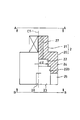
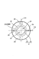
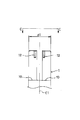
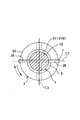
以下、本発明の一実施の形態を図面に基づいて説明する。なお、前記従来例と同一部分には同一符号を付して説明する。図1は本発明に係る開閉操作キャップの一実施の形態を示す半截正面図、図2は図1のA−A矢視図、図3は図1のB−B矢視図、図4は操作軸先端部の一実施の形態を示す正面図、図5は図4のC−C矢視図、図6は弁の開閉操作キャップの組立状態を示す半截正面図、図7は図6のD−D矢視図、図8は図6のE−E矢線断面図である。
【0011】
図1〜図3において、開閉操作キャップ2は、本体部20と角形頭部21とを有し、本体部20には、軸線C1方向の上側(奥側)から順に嵌合孔22と該嵌合孔22よりも径大の大径孔23が隣接して同心に設けられ、大径孔23は本体部20の下端に開口している。また、大径孔23の周壁部24には、その下端側から上に向かって凹入する第1の保持溝25,25と第2の保持溝26,26が軸線C1を通って直交する二直線C2,C3上に設けられており、第1の保持溝25,25の溝幅W1よりも第2の保持溝26,26の溝幅W2を僅かに大きく設定してある。さらに、角形頭部21には、その上端面から嵌合孔22まで貫通する一対のビス挿通孔27,27が軸線C1に平行して設けられている。
【0012】
図4および図5において、弁の操作軸1は中実の丸棒によってなり、少なくとも上端部(先端部)の外径d1は、開閉操作キャップ2に設けた嵌合孔22の内径d2よりも僅かに小さく、はめ合いによって嵌合孔22に着脱可能に嵌合できる値に設定されている。また、上端側から下に向かって凹入する第1の保持溝10,10と第2の保持溝11,11が軸線C1を通って直交する二直線C2,C3上に設けられており、第1の保持溝10,10の溝幅W1は、開閉操作キャップ2に設けた第1の保持溝25,25の溝幅W1と同じ値に設定され、第2の保持溝11,11の溝幅W2は、開閉操作キャップ2に設けた第2の保持溝26,26の溝幅W2と同じ値に設定されている。さらに、上端面から下向きに一対のビス用ねじ孔12,12が軸線C1に平行して設けられている。なお、これら一対のビス用ねじ孔12,12は、開閉操作キャップ2に設けた一対のビス挿通孔27,27に対応している。
【0013】
図1〜図3の開閉操作キャップ2と図4および図5の弁の操作軸1は、以下の手順によって図6〜図8のように一体に結合される。すなわち、開閉操作キャップ2の嵌合孔22に弁の操作軸1の上端部をはめ合いによって着脱可能に嵌合する。つまり、操作軸1に対して開閉操作キャップ2をはめ合いによって着脱可能に被冠する。この時、軸線C1を通って直交する直線C2上に弁の操作軸1に設けた第1の保持溝10,10と開閉操作キャップ2に設けた第1の保持溝25,25とを位置決めする。これにより、弁の操作軸1に設けた第2の保持溝11,11と開閉操作キャップ2に設けた第2の保持溝26,26は自動的に軸線C1を通って直交する直線C3上に位置決めされる。また、開閉操作キャップ2に設けた大径孔23の内面23Bと弁の操作軸1の外面1Aとの間に、後述するトルク伝達部材の折曲を許容できる折曲許容隙間8が形成される。さらに、開閉操作キャップ2に設けた一対のビス挿通孔27,27が弁の操作軸1に設けた一対のビス用ねじ孔12,12に同心に対応する。したがって、開閉操作キャップ2の上側からビス挿通孔27,27を通してビス用ねじ孔12,12にビス9,9の先端部をねじ締めることで、開閉操作キャップ2と弁の操作軸1とを一体に結合することができる。
【0014】
前記トルク伝達部材7は、板ばねのような高抗張力高弾性材料によってなり、その板厚t(図7参照)が第1の保持溝10,10と25,25に着脱可能に嵌合できる値に設定され、幅寸法(高さ)W3(図6参照)は開閉操作キャップ2に設けた第1の保持溝25,25の深さ(高さ)Hと同じ程度の寸法に設定されているとともに、長さLは開閉操作キャップ2における本体部20の外径D1よりも僅かに大きい値に設定されている。この板ばね製のトルク伝達部材7の先端を第1の保持溝25,25におけるたとえば右側の第1の保持溝25の外側にあてがった状態で左側の第1の保持溝25に向かって打ち込み、その先端部を左側の第1の保持溝25から少し突出させる。これにより、板ばね製のトルク伝達部材7は、折曲許容隙間8を介して開閉操作キャップ2に設けた第1の保持溝25,25と操作軸1に設けた第1の保持溝10,10に保持される。
【0015】
前記の手順に代えて、予め、板ばね製のトルク伝達部材7を操作軸1に設けた第1の保持溝10,10に上から落とし込んで保持させる。この時、操作軸1の径外方向両側ににはみ出す突出長さを均等に調整する。つぎに、開閉操作キャップ2を操作軸1の上側に対応させて押し下げることで、開閉操作キャップ2の嵌合孔22に弁の操作軸1の上端部をはめ合いによって着脱可能に嵌合しながら、第1の保持溝25,25に板ばね製のトルク伝達部材7を嵌合して保持させる手順によっても、板ばね製のトルク伝達部材7を、折曲許容隙間8を介して開閉操作キャップ2に設けた第1の保持溝25,25と操作軸1に設けた第1の保持溝10,10に保持することができる。その後で、開閉操作キャップ2の上側からビス挿通孔27,27を通してビス用ねじ孔12,12にビス9,9の先端部をねじ締めることで、開閉操作キャップ2と弁の操作軸1とを一体に結合することができる。
【0016】
前記構成によれば、板ばね製のトルク伝達部材7のばね力(ばね定数)によって弁の操作軸1に負荷されるトルクを設定し、設定されたトルク内では、開閉操作キャップ2と弁の操作軸1の両者を軸線C1まわりに相対回転させることなく同時に回転させることができる。つまり、板ばね製のトルク伝達部材7に軸線C1まわりの曲げ荷重が負荷されても板ばね製のトルク伝達部材7は軸線C1まわりに折曲しない。したがって、開閉操作キャップ2を図示されていない開閉手段に結合して、該開閉手段の手動または自動により開閉操作キャップ2を図8の実線矢印で示す方向に回転させると、弁の操作軸1も同じ方向に回転して、バタフライ弁B・Vをたとえば弁開操作することができる。また、開閉操作キャップ2を図8の破線矢印で示す方向に回転させると、弁の操作軸1も同じ方向に回転して、バタフライ弁B・Vをたとえば弁閉操作することができる。
【0017】
一方、何等かの原因で弁の操作軸1に設定値を超える過トルクが負荷されると、板ばね製のトルク伝達部材7に負荷される軸線C1まわりの曲げ荷重が過剰になって、板ばね製のトルク伝達部材7を折曲許容隙間8内で折曲させる。たとえば、開閉操作キャップ2を図8の実線矢印で示す方向に回転させる場合に、弁の操作軸1が軸線C1まわりに回転せず、したがって、操作軸1に設定値を超える過トルクが負荷され、板ばね製のトルク伝達部材7に負荷される実線矢印方向の曲げ荷重が過剰になって、板ばね製のトルク伝達部材7を図9に示すように折曲許容隙間8内で折曲させ、開閉操作キャップ2と弁の操作軸1の両者の軸線C1まわりの僅かな相対回転を許容する。
【0018】
この状態は、開閉操作キャップ2に結合される開閉手段が手動式であれば、弁開操作反力の急激な変動として作業者に伝わるので、その時点で開閉操作キャップ2への弁開操作力を解除することで弁が損傷するのを防止できる。また、開閉手段が自動式であれば、弁開反力の急激な変動を検知して、開閉操作キャップ2への弁開動力を解除するように構成しておくことで弁が損傷するのを防止できる。なお、開閉操作キャップ2を図8の破線矢印で示す弁閉方向に回転させる場合に、弁の操作軸1が軸線C1まわりに逆回転せず、したがって、操作軸1に設定値を超える過トルクが負荷されても、前記弁開時と同様の動作によって弁が損傷するのを防止できる。ただし、板ばね製のトルク伝達部材7は、折曲許容隙間8内で図9の逆方向に折曲することになる。
【0019】
板ばね製のトルク伝達部材7は弾性限度が大きいので、弁の操作軸1への過トルクの負荷を解除すると弾性復帰して前記折曲が消失するとともに、開閉操作キャップ2と弁の操作軸1の相対位置をもとの位置に復帰させる。すなわち、弁の操作軸1に設定値を超える過トルクが負荷された場合には、開閉操作キャップ2への弁開操作力または弁開動力を解除することで、板ばね製のトルク伝達部材7は弾性復帰して前記折曲が消失するとともに、開閉操作キャップ2と弁の操作軸1の相対位置をもとの位置に復帰させる。このように、過トルク発生時においても板ばね製のトルク伝達部材7は剪断されないので、従来のように、剪断ばりが操作軸1と開閉操作キャップ2のはめ合い面1A,2Aの隙間6に噛み込んで焼き付けをおこす不都合は発生しない。このため、板ばね製のトルク伝達部材7の交換時などにおいて、開閉操作キャップと弁の操作軸の分解を容易に行なうことができる。
【0020】
前記実施の形態では、弁の操作軸1に第1の保持溝10,10と第2の保持溝11,11を設け、開閉操作キャップ2に第1の保持溝25,25と第2の保持溝26,26を設けた構成で説明しているが、第1の保持溝10,10と第1の保持溝25,25のみを設けた構成または第2の保持溝11,11と第2の保持溝26,26のみを設けた構成であってもよい。ただし、前記実施の形態のように構成しておけば、第1の保持溝10,10、25,25に保持されている板ばね製のトルク伝達部材7に代えて、板厚とばね力(ばね定数)の大きい第2の板ばね製のトルク伝達部材7(図示省略)を第2の保持溝11,11、26,26に嵌合して保持することで、弁の操作軸1に負荷される過トルクを調整して大きくすることができる。
【0021】
また、第1の保持溝10,10と第2の保持溝11,11以外に溝幅の異なる第3〜第4の保持溝を弁の操作軸1に設け、これら第3〜第4の保持溝に対応して該第3〜第4の保持溝と同じ溝幅の第3〜第4の保持溝を開閉操作キャップ2に設けるとともに、板厚とばね力が互いに異なり第3〜第4の保持溝に嵌合して保持される第3〜第4の板ばね製のトルク伝達部材7を別途用意し、これらを選択して使用することで、弁の操作軸1に負荷される過トルクの調整幅を拡大することができる。
【0022】
さらに、図10および図11に示すように、第1の角形保持孔溝10A,10Aと第1の角形保持孔25A,25Aを設けるとともに、第2の角形保持孔11A,11Aと第2の角形保持孔26A,26Aを設けて、板ばね製のトルク伝達部材7を、折曲許容隙間8を介して、たとえば開閉操作キャップ2に設けた第1の角形保持孔25A,25Aと操作軸1に設けた第1の角形保持孔10A,10Aに嵌合して保持するように構成してもよい。このような構成であれば、前述のビス9,9を不要にして開閉操作キャップ2と弁の操作軸1とを一体に結合することができる。
【0023】
なお、前記実施の形態では、弁の開閉操作キャップ2をバタフライ弁B・Vの操作軸1に取付けて説明しているが、本発明は、ボール弁やゲート弁のような回転弁の操作軸にも取付けることができる。
【0024】
【発明の効果】
以上説明したように、本発明の弁の開閉操作キャップは構成されているので、以下のような格別な効果を奏する。
【0025】
すなわち、過トルク発生時においても板ばね製のトルク伝達部材は剪断されないので、従来のように、剪断ばりが操作軸と開閉操作キャップのはめ合い面の隙間に噛み込んで焼き付けをおこす不都合は発生しない。このため、板ばね製のトルク伝達部材の交換時などにおいて、開閉操作キャップと弁の操作軸の分解を容易に行なうことができる。
【図面の簡単な説明】
【図1】本発明に係る開閉操作キャップの一実施の形態を示す半截正面図である。
【図2】図1のA−A矢視図である。
【図3】図1のB−B矢視図である。
【図4】操作軸先端部の一実施の形態を示す正面図である。
【図5】図4のC−C矢視図である。
【図6】開閉操作キャップの組立状態の一例を示す半截正面図である。
【図7】図6のD−D矢視図である。
【図8】図6のE−E線断面図である。
【図9】板ばね製のトルク伝達部材の折曲状態を拡大して示す説明平面図である。
【図10】本発明に係る開閉操作キャップの他の実施の形態を示す半截正面図である。
【図11】図10のF−F線断面である。
【図12】従来例を一部断面にして示す正面図である。
【図13】弁の開閉操作キャップをバタフライ弁に取付けた使用例を示す正面図である。
【符号の説明】
1 弁の操作軸
1A 弁の操作軸の外面
2 開閉操作キャップ
7 板ばね製のトルク伝達部材(高抗張力高弾性材料によってなるトルク伝達部材)
8 折曲許容隙間
10 第1の保持溝(弁の操作軸に設けた保持孔)
10A 第1の角形保持孔(弁の操作軸に設けた保持孔)
11 第2の保持溝(弁の操作軸に設けた保持孔)
11A 第2の角形保持孔(弁の操作軸に設けた保持孔)
22 嵌合孔
23 大径孔
23B 大径孔の内面
25 第1の保持溝(開閉操作キャップに設けた保持孔)
25A 第1の角形保持孔(開閉操作キャップに設けた保持孔)
26 第2の保持溝(開閉操作キャップに設けた保持孔)
26A 第2の角形保持孔(開閉操作キャップ弁に設けた保持孔)
22 嵌合孔[0001]
TECHNICAL FIELD OF THE INVENTION
The present invention relates to an opening / closing operation cap for a valve, for example, to an opening / closing operation cap attached to a distal end portion of an operation shaft of a butterfly valve.
[0002]
[Prior art]
A conventionally known valve opening / closing operation cap is, for example, as shown in FIG. 12 and FIG. 13, an opening / closing operation cap 2 is fitted to and detached from a distal end portion of a valve operation shaft 1 in a butterfly valve B / V. A torque transmission pin 4 is screwed through the torque transmission pin mounting hole 3 provided in the opening / closing operation cap 2 and screwed into the torque transmission pin insertion hole 5 provided in the distal end portion of the operation shaft 1. The operation shaft 1 and the opening / closing operation cap 2 are connected to each other so that they cannot rotate relative to each other.
[0003]
In this type of opening / closing operation cap for a valve, the opening / closing operation cap 2 is coupled to opening / closing means (not shown), and the opening / closing operation cap 2 is rotated in the forward / reverse direction by manual or automatic operation of the opening / closing means. Can be simultaneously rotated in the forward and reverse directions to open and close the butterfly valves B and V.
[0004]
In addition, in this type of valve opening / closing operation cap, an excessive torque (hereinafter, referred to as overtorque) exceeding a set value is applied to the operation shaft 1 of the butterfly valve B / V at the time of opening / closing the butterfly valve B / V. In this case, in order to prevent the butterfly valves B and V from being damaged, the cross-sectional area of the torque transmission pin 4 is set so that the torque transmission pin 4 is sheared by the excessive torque.
[0005]
[Problems to be solved by the invention]
However, a tight tolerance is required for the fitting between the operation shaft 1 of the valve and the opening / closing operation cap 2. Therefore, the outer surface (fitting surface) 1 </ b> A of the tip of the operating shaft 1 and the inner surface (fitting surface) 2 </ b> A of the opening / closing operation cap 2. Is set to an extremely small value. For this reason, the shearing burrs generated when the torque transmitting pin 4 is sheared bite into the gap 6 and cause burning. Therefore, although the butterfly valves B and V can be prevented from being damaged by the shearing of the torque transmission pin 4, it is extremely difficult to disassemble the opening / closing operation cap 2 from the valve operation shaft 1 to replace the torque transmission pin 4. become.
[0006]
The present invention has been made in view of such circumstances, and a valve that can easily disassemble an opening / closing operation cap and an operation shaft of a valve by avoiding shearing of a torque transmission member even when overtorque occurs. The purpose of the present invention is to provide an opening / closing operation cap.
[0007]
[Means for Solving the Problems]
In order to achieve the above object, a valve opening / closing operation cap according to the present invention includes a valve operation shaft, an opening / closing operation cap that is detachably covered by being fitted to the operation shaft, an opening / closing operation cap, and a valve. In an opening / closing operation cap of a valve in which both of the operation shafts are connected via a torque transmitting member so that relative rotation around an axis within a set torque is impossible, the operation shaft of the valve is fitted to the opening / closing operation cap by fitting. A fitting hole and a large-diameter hole having an inner diameter larger than the fitting hole are provided, and a bending allowance capable of allowing the torque transmission member to bend between the inner surface of the large-diameter hole and the outer surface of the operation shaft of the valve. A gap is formed, and a torque transmission member made of a high tensile strength and high elastic material is held in holding holes provided in both the opening / closing operation cap and the operation shaft through the bending allowable gap.
[0008]
According to the present invention, the torque applied to the operating shaft of the valve is set by the elasticity of the torque transmitting member made of a high tensile strength and high elastic material, and both the opening / closing operation cap and the operating shaft of the valve are set within the set torque. They can be rotated simultaneously without relative rotation about the axis. That is, even if a bending load around the axis is applied to the torque transmitting member plate, the plate does not bend around the axis.
[0009]
On the other hand, when an over-torque exceeding a set value is applied to the operation shaft, a bending load around the axis applied to the torque transmitting member plate made of a high tensile strength and high elasticity material becomes excessive, and the torque transmitting member is bent. The valve is bent within the allowable bending gap, and functions to prevent the valve from being damaged by permitting relative rotation of both the opening / closing operation cap and the operation shaft of the valve around the axis. Since the torque transmission member has a large elastic limit, when the over-torque load on the operation shaft is released, the operation returns to elastic and the bending disappears. To return to.
[0010]
BEST MODE FOR CARRYING OUT THE INVENTION
An embodiment of the present invention will be described below with reference to the drawings. The same parts as those in the conventional example are denoted by the same reference numerals and described. FIG. 1 is a partially cutaway front view showing an embodiment of the opening / closing operation cap according to the present invention, FIG. 2 is a view along arrow AA in FIG. 1, FIG. 3 is a view along arrow BB in FIG. FIG. 5 is a front view showing an embodiment of a tip portion of an operation shaft, FIG. 5 is a view taken along the line CC of FIG. 4, FIG. 6 is a half-cut front view showing an assembled state of a valve opening / closing operation cap, and FIG. FIG. 8 is a sectional view taken along the line EE of FIG.
[0011]
1 to 3, the opening / closing operation cap 2 has a main body 20 and a square head 21. The main body 20 has a fitting hole 22 and a fitting hole 22 in order from the upper side (back side) in the direction of the axis C1. A large-diameter hole 23 having a diameter larger than the joint hole 22 is provided adjacently and concentrically, and the large-diameter hole 23 is opened at the lower end of the main body 20. In the peripheral wall portion 24 of the large-diameter hole 23, first holding grooves 25, 25 and second holding grooves 26, 26, which are recessed upward from the lower end thereof, are orthogonal to each other through the axis C1. The groove widths W2 of the second holding grooves 26, 26 are provided on the straight lines C2, C3, and are slightly larger than the groove width W1 of the first holding grooves 25, 25. Further, a pair of screw insertion holes 27, 27 penetrating from the upper end surface to the fitting hole 22 are provided in the rectangular head 21 in parallel with the axis C1.
[0012]
4 and 5, the operation shaft 1 of the valve is made of a solid round bar, and the outer diameter d1 of at least the upper end (tip) is larger than the inner diameter d2 of the fitting hole 22 provided in the opening / closing operation cap 2. It is slightly smaller and is set to a value that allows it to be removably fitted into the fitting hole 22 by fitting. Further, the first holding grooves 10, 10 and the second holding grooves 11, 11, which are recessed downward from the upper end side, are provided on two straight lines C2, C3 orthogonal to each other through the axis C1. The groove width W1 of the first holding grooves 10, 10 is set to the same value as the groove width W1 of the first holding grooves 25, 25 provided in the opening / closing operation cap 2, and the groove width of the second holding grooves 11, 11 is set. W2 is set to the same value as the groove width W2 of the second holding grooves 26 provided in the opening / closing operation cap 2. Further, a pair of screw screw holes 12, 12 are provided downward from the upper end surface in parallel with the axis C1. The pair of screw screw holes 12 correspond to a pair of screw insertion holes 27 provided in the opening / closing operation cap 2.
[0013]
The opening / closing operation cap 2 in FIGS. 1 to 3 and the operation shaft 1 of the valve in FIGS. 4 and 5 are integrally connected as shown in FIGS. That is, the upper end of the operation shaft 1 of the valve is removably fitted into the fitting hole 22 of the opening / closing operation cap 2 by fitting. That is, the opening / closing operation cap 2 is removably covered with the operation shaft 1 by fitting. At this time, the first holding grooves 10, 10 provided in the valve operating shaft 1 and the first holding grooves 25, 25 provided in the opening / closing operation cap 2 are positioned on a straight line C2 orthogonal to the axis C1. . As a result, the second holding grooves 11 and 11 provided in the valve operating shaft 1 and the second holding grooves 26 and 26 provided in the opening / closing operation cap 2 automatically move on the straight line C3 orthogonal to the axis C1. Positioned. Further, between the inner surface 23B of the large-diameter hole 23 provided in the opening / closing operation cap 2 and the outer surface 1A of the operation shaft 1 of the valve, there is formed a bendable gap 8 that can allow the torque transmission member to be described later. . Further, a pair of screw insertion holes 27 provided in the opening / closing operation cap 2 correspond to a pair of screw screw holes 12 provided in the operation shaft 1 of the valve. Therefore, by opening and closing the opening and closing operation cap 2 and the operation shaft 1 of the valve by screwing the tips of the screws 9 and 9 into the screw screw holes 12 and 12 through the screw insertion holes 27 and 27 from the upper side of the opening and closing operation cap 2. Can be combined.
[0014]
The torque transmitting member 7 is made of a high tensile strength and high elastic material such as a leaf spring, and has a plate thickness t (see FIG. 7) that can be detachably fitted to the first holding grooves 10, 10, 25, 25. , And the width dimension (height) W3 (see FIG. 6) is set to be substantially the same as the depth (height) H of the first holding grooves 25 provided in the opening / closing operation cap 2. At the same time, the length L is set to a value slightly larger than the outer diameter D1 of the main body 20 in the opening / closing operation cap 2. The leaf spring torque transmitting member 7 is driven toward the left first holding groove 25 in a state where the tip of the torque transmitting member 7 is applied to the first holding grooves 25, 25, for example, outside the right first holding groove 25. The tip is slightly projected from the left first holding groove 25. Thus, the torque transmitting member 7 made of a leaf spring is provided with the first holding grooves 25 provided on the opening / closing operation cap 2 and the first holding grooves 10 provided on the operation shaft 1 via the bending allowance 8. It is held at 10.
[0015]
Instead of the above-described procedure, the torque transmitting member 7 made of a leaf spring is dropped and held in the first holding grooves 10 provided on the operation shaft 1 in advance. At this time, the protruding lengths of the operation shaft 1 protruding outward on both sides in the radial direction are uniformly adjusted. Next, by pushing down the opening / closing operation cap 2 corresponding to the upper side of the operation shaft 1, the upper end of the operation shaft 1 of the valve is removably fitted to the fitting hole 22 of the opening / closing operation cap 2 by fitting. The torque transmitting member 7 made of a leaf spring is also fitted and held in the first holding grooves 25, 25, and the opening / closing operation cap is 2 and the first holding grooves 10, 10 provided in the operation shaft 1. After that, the tip of the screw 9, 9 is screwed into the screw screw hole 12, 12 through the screw insertion hole 27, 27 from above the opening / closing operation cap 2, and the opening / closing operation cap 2 and the operating shaft 1 of the valve are connected. They can be joined together.
[0016]
According to the configuration, the torque applied to the operation shaft 1 of the valve is set by the spring force (spring constant) of the torque transmission member 7 made of a leaf spring, and the opening / closing operation cap 2 and the valve are set within the set torque. Both of the operation shafts 1 can be rotated simultaneously without relative rotation about the axis C1. That is, even when a bending load around the axis C1 is applied to the leaf spring torque transmitting member 7, the leaf spring torque transmitting member 7 does not bend around the axis C1. Therefore, when the opening / closing operation cap 2 is connected to opening / closing means (not shown) and the opening / closing operation cap 2 is manually or automatically rotated in the direction indicated by the solid arrow in FIG. By rotating in the same direction, the butterfly valves BV can be operated, for example, to open the valves. When the opening / closing operation cap 2 is rotated in the direction indicated by the dashed arrow in FIG. 8, the operation shaft 1 of the valve also rotates in the same direction, and the butterfly valves B and V can be closed, for example.
[0017]
On the other hand, if an excessive torque exceeding the set value is applied to the operation shaft 1 of the valve for some reason, the bending load around the axis C1 applied to the torque transmission member 7 made of a leaf spring becomes excessive, The torque transmitting member 7 made of a spring is bent in the bending allowable gap 8. For example, when the opening / closing operation cap 2 is rotated in the direction indicated by the solid line arrow in FIG. 8, the operation shaft 1 of the valve does not rotate around the axis C1, and therefore, an excessive torque exceeding the set value is applied to the operation shaft 1. When the bending load in the direction of the solid line arrow applied to the leaf spring torque transmitting member 7 becomes excessive, the leaf spring torque transmitting member 7 is bent in the bending allowable gap 8 as shown in FIG. A slight relative rotation of the opening / closing operation cap 2 and the valve operation shaft 1 around the axis C1 is allowed.
[0018]
In this state, if the opening / closing means coupled to the opening / closing operation cap 2 is of a manual type, it is transmitted to the operator as a sudden change in the valve opening operation reaction force. By canceling, the valve can be prevented from being damaged. If the opening / closing means is of an automatic type, the valve may be damaged by detecting a sudden change in the valve opening reaction force and releasing the valve opening power to the opening / closing operation cap 2. Can be prevented. When the opening / closing operation cap 2 is rotated in the valve closing direction indicated by the dashed arrow in FIG. 8, the operation shaft 1 of the valve does not reversely rotate around the axis C <b> 1. Can be prevented from being damaged by the same operation as when the valve is opened. However, the torque transmission member 7 made of a leaf spring is bent in the direction opposite to the direction shown in FIG.
[0019]
Since the torque transmission member 7 made of a leaf spring has a large elastic limit, when the over-torque load on the valve operating shaft 1 is released, the valve returns elastically and the bending disappears. The relative position of 1 is returned to the original position. That is, when an over-torque exceeding the set value is applied to the operation shaft 1 of the valve, the valve opening operation force or the valve opening power to the opening / closing operation cap 2 is released to release the torque transmission member 7 made of a leaf spring. Resiliently restores the bend and the relative position between the opening / closing operation cap 2 and the operation shaft 1 of the valve returns to the original position. As described above, even when excessive torque is generated, the torque transmitting member 7 made of a leaf spring is not sheared, so that the shearing burrs are formed in the gap 6 between the fitting surfaces 1A and 2A of the operating shaft 1 and the opening / closing operating cap 2 as in the related art. The inconvenience of biting and burning does not occur. For this reason, the disassembly of the opening / closing operation cap and the operation shaft of the valve can be easily performed, for example, when replacing the torque transmission member 7 made of a leaf spring.
[0020]
In the above embodiment, the first holding grooves 10 and 10 and the second holding grooves 11 and 11 are provided on the operation shaft 1 of the valve, and the first holding grooves 25 and 25 and the second holding groove are provided on the opening / closing operation cap 2. Although the description has been given of the configuration in which the grooves 26, 26 are provided, the configuration in which only the first holding grooves 10, 10 and the first holding grooves 25, 25 are provided, or the second holding grooves 11, 11, and the second A configuration in which only the holding grooves 26, 26 are provided may be employed. However, if configured as in the above embodiment, the plate thickness and spring force (instead of the plate spring torque transmitting member 7 held in the first holding grooves 10, 10, 25, 25) are used. A torque transmission member 7 (not shown) made of a second leaf spring having a large spring constant) is fitted and held in the second holding grooves 11, 11, 26, 26, so that a load is applied to the operation shaft 1 of the valve. It can be increased by adjusting the overtorque to be performed.
[0021]
Further, in addition to the first holding grooves 10 and 10 and the second holding grooves 11 and 11, third and fourth holding grooves having different groove widths are provided on the operation shaft 1 of the valve, and these third and fourth holding grooves are provided. Third and fourth holding grooves having the same groove width as the third and fourth holding grooves are provided in the opening / closing operation cap 2 corresponding to the grooves, and the third and fourth holding grooves have different plate thicknesses and spring forces. The third and fourth leaf spring-made torque transmitting members 7 fitted and held in the holding grooves are separately prepared, and selected and used, whereby an excessive torque applied to the valve operating shaft 1 is obtained. Can be widened.
[0022]
Further, as shown in FIGS. 10 and 11, first rectangular holding hole grooves 10A, 10A and first rectangular holding holes 25A, 25A are provided, and second rectangular holding holes 11A, 11A and the second rectangular holding holes are provided. The holding holes 26A, 26A are provided, and the torque transmission member 7 made of a leaf spring is connected to the first square holding holes 25A, 25A provided in the opening / closing operation cap 2 and the operation shaft 1 through the bending allowable gap 8, for example. You may comprise so that it may fit and hold in the provided 1st square holding hole 10A, 10A. With such a configuration, the opening and closing operation cap 2 and the operation shaft 1 of the valve can be integrally connected without the need for the screws 9 and 9 described above.
[0023]
In the above embodiment, the valve opening / closing operation cap 2 is attached to the operation shaft 1 of the butterfly valve B / V. However, the present invention is not limited to the operation shaft of a rotary valve such as a ball valve or a gate valve. Can also be mounted.
[0024]
【The invention's effect】
As described above, since the valve opening / closing operation cap of the present invention is configured, the following special effects can be obtained.
[0025]
That is, even when over-torque occurs, the torque transmitting member made of a leaf spring is not sheared. do not do. For this reason, the disassembly of the opening / closing operation cap and the operation shaft of the valve can be easily performed, for example, when replacing the torque transmission member made of a leaf spring.
[Brief description of the drawings]
FIG. 1 is a half sectional front view showing an embodiment of an opening / closing operation cap according to the present invention.
FIG. 2 is a view as viewed in the direction of arrows AA in FIG. 1;
FIG. 3 is a view taken in the direction of arrows BB in FIG. 1;
FIG. 4 is a front view showing an embodiment of a tip portion of an operation shaft.
FIG. 5 is a view taken in the direction of the arrows CC in FIG. 4;
FIG. 6 is a half-cut front view showing an example of an assembled state of the opening / closing operation cap.
FIG. 7 is a view as viewed in the direction of the arrow DD in FIG. 6;
FIG. 8 is a sectional view taken along line EE of FIG. 6;
FIG. 9 is an enlarged plan view showing a bent state of a leaf spring torque transmitting member.
FIG. 10 is a half sectional front view showing another embodiment of the opening / closing operation cap according to the present invention.
11 is a sectional view taken along line FF of FIG. 10;
FIG. 12 is a front view showing a conventional example with a partial cross section.
FIG. 13 is a front view showing a usage example in which a valve opening / closing operation cap is attached to a butterfly valve.
[Explanation of symbols]
DESCRIPTION OF SYMBOLS 1 Operating shaft of valve 1A Outer surface of operating shaft of valve 2 Opening / closing operation cap 7 Torque transmitting member made of leaf spring (torque transmitting member made of high tensile strength and high elasticity material)
8 Allowable bending gap 10 First holding groove (holding hole provided in valve operation shaft)
10A 1st square holding hole (holding hole provided in the operation shaft of valve)
11 Second holding groove (holding hole provided in valve operation shaft)
11A 2nd square holding hole (holding hole provided in valve operation shaft)
22 fitting hole 23 large-diameter hole 23B inner surface 25 of large-diameter hole First holding groove (holding hole provided in opening / closing operation cap)
25A First rectangular holding hole (holding hole provided in opening / closing operation cap)
26 Second holding groove (holding hole provided in opening / closing operation cap)
26A 2nd square holding hole (holding hole provided in opening / closing operation cap valve)
22 Mating hole