JP2004006255A - Marker lamp - Google Patents
Marker lamp Download PDFInfo
- Publication number
- JP2004006255A JP2004006255A JP2003042056A JP2003042056A JP2004006255A JP 2004006255 A JP2004006255 A JP 2004006255A JP 2003042056 A JP2003042056 A JP 2003042056A JP 2003042056 A JP2003042056 A JP 2003042056A JP 2004006255 A JP2004006255 A JP 2004006255A
- Authority
- JP
- Japan
- Prior art keywords
- light
- lamp
- xenon lamp
- light source
- phosphorescent material
- Prior art date
- Legal status (The legal status is an assumption and is not a legal conclusion. Google has not performed a legal analysis and makes no representation as to the accuracy of the status listed.)
- Pending
Links
Images


Abstract
Description
【0001】
【発明の属する技術分野】
本発明は、主に標示ランプに関しキセノンランプからなる光源と、蓄光材の両方の特性を利用し発光させて、被視認性を向上させたものである。
【0002】
【従来の技術】
従来、この種の標示ランプとしては、LEDや白熱電球からなる光源とアルミなどの反射材を併用使用して装着し、被視認性を確保しているのが一般的であるが、更には自発光で視覚に強く訴えるものが要求されている。現状では消費電力、コストの面での制約があり、唯一自発光で電力の追加なしでできるのが蓄光材である。蓄光材については光源との組み合わせによる照明技術が、多く紹介されている。内容としては、以下に集約される。
(1)蓄光材シートに、別に設けられた外部光源から光を照射し、蓄光材シートを励起発光させ、蓄光材シートそのものを標識灯として利用する。
(特開平8−137419参照)
(2)内部に、光源を備えるランプケースに蓄光材シートを貼付し、蓄光の励起光を標識として利用する。
(特願平9−183029参照)
(3)蛍光ランプの外側に蓄光材を塗布し、蛍光ランプを消灯した後、蓄光材からの励起残光を照明として利用する。
(特開平9−55189参照)
これ等の技術は、(1)(2)については、光源と蓄光材が一体でなく独立して設けられており、蓄光効率が悪く、又レンズ、反射鏡を使って標示ランプとして自在に光学設計ができない。(3)については、標示ランプでなく照明ランプして使用するものであるが、これも(1)(2)の理由と同様、光源として蓄光材を使用したものでないため、レンズや反射鏡等の光源系を使った標示ランプとは基本的に異なるものである。
【0003】
【発明が解決しようとする課題】
しかしながら、LEDや白熱電球からなる光源の標示ランプは、自転車等軽車両の走行などに使用するには明るさが不足したり、又逆に消費電力が大きすぎるという問題点があり、現在は光源を使わない反射器のみの装着で普及している。消費電力を増やさず自発光できるものとして蓄光材が考えられるが、標示ランとして蓄光材を使用するには、励起光の明るさを増大するための飛躍的な解決策が必要であり、これを解決することができれば標示ランプとしての用途は大きく拡大される。
【0004】
このようなことから本発明は自発光で明るく、且つ消費電力が少なく、更に新規性のある励起発光を導入し、十分な明るさが得られる標示装置の開発により被視認機能を向上させる。
【0005】
【課題を解決するための手段】
本発明は、上述した点に鑑みたもので、ケース状をなす標示ランプの、標示部分を構成する透明な外郭部材の内側に、キセノンランプからなる光源と、キセノンランプの間欠点灯を補完する目的で、キセノンランプ間欠消灯時に光エネルギーを放出させるための蓄光材を設け、更にその蓄光材をより効果的に利用するためキセノンランプに近づけ、これを一体化し一個の光源とし、キセノンランプと蓄光励起光との2機能ランプを実現させ、又この光源を光学系の焦点近傍に位置させ光学設計によって、自由度を広げ用途に応じた配光設計が得られる明るい標示ランプの実現化を目指し、又間欠点灯するキセノンランプの光と蓄光材からの励起光を合体させたキセノンランプの強い閃光の特長を生かし、且つ各閃光間を蓄光材の励起光で補完し連続した光を出す標示ランプを開発することにある。
【0006】
【発明の実施の形態】
以下、本発明の標示ランプにおける一実施例について、図を参照しながら説明する。
【0007】
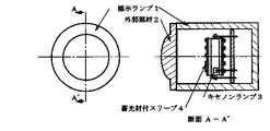
図1は、標示ランプの外形を示した図で、標示ランプ1,の透明な外郭部材2,の内側に、キセノンランプ3,と蓄光材付スリーブ4,の装着状態を示したものである。ここでは透明な外郭部材2,は光学系の一つの例を図で凸レンズを示したものであり、この凸レンズを通過したキセノンランプの光束と、同時に発光する蓄光材の励起光が制御されることになる。
【0008】
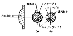
図2(a)(b)は、キセノンランプ3,の周りにスリーブ5,を設け、そのスリーブに蓄光材6,を被覆又は煉り込ませたものである。
【0009】
図3(a)は、キセノンランプ3,に直接蓄光材6,を被覆したものである。
【0010】
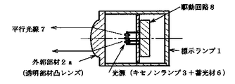
図4は、本発明の使用例を示すもので外郭部材2a,を凸レンズとし、光学系の焦点近傍に置かれた光源(キセノンランプ3+蓄光材6)からの光を、凸レンズにより制御し平行光線7,にまとめ標示ランプとしたものである。
【0011】
図5は、本発明の使用例を示すもので外郭部材2a,を平レンズ又は平板とし、その代替えとして光源の後部に回転放物面反射鏡9,又は類似反射鏡を設け、光源からの光を反射させ制御し平行光線7,にまとめ標示ランプとしたものである。
【0012】
図6は、キセノンランプの閃光の裸光度を示すものでキセノンランプ駆動回路を含めたキセノンランプの閃光の特性は次の通りである。
閃光数180回/分、消費電力10W、裸光度15万cd。
キセノンランプの閃光は、エネルギーが瞬間的に発光されるため測定値としては15万cd以上として記載した。
【0013】
図7(a)は、図6で示したキセノンランプの閃光を蓄光材に照射してその残光輝度を測定したものである。蓄光材の試料は厚さ200mg/cm2、組成ZnS:Cuを使用した。又縦軸は輝度(cd/m2)、横軸は時間(分)で示した。
図7(b)は、図7(a)の横軸と時間(秒)で示したものである。蓄光材の励起光は,被照射時間を秒単位で繰り返すことによって高輝度が得られる。
【0014】
図8は、図6で示した測定値と図7(b)で示した測定値を合成したもので、キセノンランプの間欠点灯を蓄光材の励起光で補完した状態図を示すもので全体としては連続的な配光パターンを形成している、又蓄光材の励起光の明るさはピーク時で約10(cd/m2)の値が得られており,この値は標識灯に関するJIS Z5100で示されている5分後の蓄光材の残光値20(mcd/m2)以上に比べると問題ない値である。
【0015】
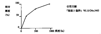
図9は、励起光を得るために蓄光材に与えるエネルギー(照度で評価)と蓄光材からの励起光の輝度を示すもので、蓄光材には大きなエネルギーを与えればそのぶん励起光の輝度も大きくなることは当然であるが、限られた光源を使用する場合には、光源を蓄光材にできる限り近づける方が有利となる(距離の二乗で光度を除いた値が照度となる)。従って、本発明ではキセノンランプと蓄光材を一体化して使用するものである。
【0016】
図10は、蓄光材の厚みと励起光の輝度との関係を示すもので、800〜1000μm程度までは厚みを増した方がよい。したがって蓄光材の使い方としては、蓄光材の厚みを最大まで利用する方が有利であるが一方では標示面が大きい場合蓄光材の使用量も大きくなる。本発明では、キセノンランプと一体化して使用するものであり蓄光材は少量でよい。従って、全体としては図9、図10の効果を合わせ、本発明のキセノンランプと蓄光材を一体化して使用することに優位性を見出した。
【0017】
【発明の効果】
本発明は、以上説明したように、標示ランプ1,の、キセノンランプ3,及び蓄光材6,を一体化し且つ標示ランプ1,の光学系の焦点位置近傍に配置することにより、キセノンランプ3,の閃光と同時に励起される蓄光材6,の励起光が標示ランプ1,より同時に放射され標示ランプ1,としての設計の自由度を増大させる。蓄光材6,の励起光の増大、キセノンランプの閃光と励起光を同時に一つの標示ランプ1,に利用できる。キセノンランプ3,の閃光が間欠であっても励起光によりその間を補完し連続光となる。更に光源が焦点位置にあるため光学設計により集光拡散が自由となり状況に応じた標示ランプ1,の設計ができる。
【図面の簡単な説明】
【図1】本発明の標示ランプ1,の概略図で、キセノンランプ3,蓄光材付スリーブ4,の使用例を示す。
【図2】本発明の詳細、スリーブ5,への蓄光材6,の被覆例を示す。
【図3】本発明の詳細、キセノンランプ3,への蓄光材6,の被覆例を示す。
【図4】本発明の実施例を示したもので、キセノンランプ3,は、充電抵抗、トリガーコンデンサー、主コンデンサー等から構成されている駆動回路8,により点灯されるキセノンランプ3,が、閃光点灯されると同時に蓄光材6,が励起され発光する。この2種類の光が外郭部材2a,(凸レンズ)により制御され平行光線7,となり、光源からの光が集光された状態を示す。
【図5】本発明の他の実施例を示したもので図3の外郭部材2a,(凸レンズ)の代わりに外郭部材2b,(平面レンズ)とし、光の制御については光源(キセノンランプ3+蓄光材6)の後部に回転放物面反射鏡9,を設け、光を反射制御し光源からの平行光線7,とし光源からの光が集光された状態を示す。
【図6】キセノンランプから放射されるエネルギーを裸光度で測定したグラフを示す。
【図7】(a),(b)図6で測定したキセノンランプを蓄光材に照射して、蓄光材の残光輝度性を示したもので、蓄光材は時間の経過と共に輝度低下は著しいが秒単位では高い輝度が得られる。図7(a)は、横軸を時間(分)、図7(b)は、横軸を時間(秒)で示したものである。
【図8】キセノンランプの光度測定した図6と、蓄光材からの励起光の輝度を図7(b)で示した秒単位のもののみのデータを使って合成した状態図を示す。
【図9】蓄光材を励起するための照度と、その明るさによって励起された輝度との関係を示す。
【図10】蓄光材の厚みと、残光輝度の関係につき示す。蓄光材は基本的に厚くする方が励起光は明るくなる。輝度の増加率は小さくなる。
【符号の説明】
1 標示ランプ
2 外郭部材
2a 外郭部材(透明部材凸レンズ)
2b 外郭部材(透明部材平レンズ)
3 キセノンランプ
4 蓄光材付スリーブ
5 スリーブ
6 蓄光材
7 平行光線
8 駆動回路
9 回転放物面反射鏡[0001]
TECHNICAL FIELD OF THE INVENTION
The present invention mainly relates to a sign lamp, in which light is emitted by utilizing characteristics of both a light source composed of a xenon lamp and a light storage material to improve visibility.
[0002]
[Prior art]
Conventionally, this type of indicator lamp is generally mounted using a light source such as an LED or an incandescent light bulb and a reflective material such as aluminum to ensure visibility, but furthermore, it is more self-contained. There is a demand for something that appeals to the eyes with luminescence. At present, there are restrictions in terms of power consumption and cost, and the only thing that can be done with self-luminous light without adding power is a luminous material. As for the phosphorescent material, many lighting techniques using a combination with a light source are introduced. The contents are summarized below.
(1) The phosphorescent sheet is irradiated with light from an external light source provided separately to excite the phosphorescent sheet to emit light, and the phosphorescent sheet itself is used as a marker lamp.
(See Japanese Patent Application Laid-Open No. 8-137419)
(2) Inside, a phosphorescent material sheet is attached to a lamp case having a light source, and the phosphorescent excitation light is used as a marker.
(See Japanese Patent Application No. 9-183029)
(3) A phosphorescent material is applied to the outside of the fluorescent lamp, and after the fluorescent lamp is turned off, the afterglow of excitation from the phosphorescent material is used as illumination.
(See JP-A-9-55189)
In these technologies, regarding (1) and (2), the light source and the luminous material are provided independently of each other instead of being integrated, and the luminous efficiency is poor. Can't design. As for (3), it is used as an illumination lamp instead of a sign lamp. However, since the light source is not a light storage material as in (1) and (2), the lens and the reflecting mirror are used. The lamp is basically different from the sign lamp using the light source system.
[0003]
[Problems to be solved by the invention]
However, the indicator lamp of a light source including an LED or an incandescent light bulb has a problem that the brightness is insufficient for use in running a light vehicle such as a bicycle or the power consumption is too large. Widely used with only reflectors that don't use Luminescent materials can be considered to be capable of self-emission without increasing power consumption.However, the use of a luminous material as a labeling run requires a dramatic solution to increase the brightness of the excitation light. If it can be solved, the application as a sign lamp will be greatly expanded.
[0004]
In view of the above, the present invention improves self-luminous function by introducing a novel self-luminous, low power consumption, and novel excitation light emission, and developing a sign device capable of obtaining sufficient brightness.
[0005]
[Means for Solving the Problems]
The present invention has been made in view of the above points, and has an object of complementing intermittent lighting of a xenon lamp light source and a xenon lamp light source inside a transparent outer member constituting a marking portion of a case-shaped marking lamp. Therefore, a phosphorescent material for emitting light energy when the xenon lamp is intermittently turned off is provided, and the phosphorescent material is brought closer to the xenon lamp in order to use it more effectively. With the aim of realizing a bright indicator lamp that realizes a two-function lamp with light, locates this light source near the focal point of the optical system, and expands the degree of freedom by means of optical design and obtains a light distribution design according to the application. Take advantage of the strong flash characteristics of the xenon lamp, which combines the light of the xenon lamp that is intermittently lit and the excitation light from the phosphorescent material, and complement each flash with the excitation light of the phosphorescent material. It is to develop an indication lamp to emit a series of light.
[0006]
BEST MODE FOR CARRYING OUT THE INVENTION
Hereinafter, an embodiment of the sign lamp of the present invention will be described with reference to the drawings.
[0007]
FIG. 1 is a view showing the outer shape of the sign lamp, and shows a mounted state of a xenon lamp 3 and a sleeve 4 with a luminous material inside a transparent outer member 2 of the sign lamp 1. Here, the transparent outer member 2 is a diagram showing an example of an optical system as a convex lens, and the luminous flux of the xenon lamp passing through the convex lens and the excitation light of the light storage material that emits light at the same time are controlled. become.
[0008]
2 (a) and 2 (b), a
[0009]
FIG. 3A shows a xenon lamp 3 in which a phosphorescent material 6 is directly coated.
[0010]
FIG. 4 shows an example of use of the present invention, in which the outer member 2a is a convex lens, and the light from the light source (xenon lamp 3 + light storage material 6) placed near the focal point of the optical system is controlled by the convex lens to form a parallel light beam. This is a sign lamp summarized in Fig. 7.
[0011]
FIG. 5 shows an example of the use of the present invention. The outer member 2a is a flat lens or a flat plate. As an alternative, a rotating parabolic reflector 9 or a similar reflector is provided at the rear of the light source, and the light from the light source is provided. Are reflected and controlled to be combined into parallel rays 7 to form a sign lamp.
[0012]
FIG. 6 shows the luminous intensity of the flash light of the xenon lamp. The flash characteristics of the xenon lamp including the xenon lamp driving circuit are as follows.
180 flashes / minute, power consumption 10 W, bare light intensity 150,000 cd.
The flash of a xenon lamp is described as a measured value of 150,000 cd or more because energy is emitted instantaneously.
[0013]
FIG. 7A shows the result of measuring the afterglow luminance of a phosphorescent material irradiated with the flash of the xenon lamp shown in FIG. A sample of the phosphorescent material used was ZnS: Cu with a thickness of 200 mg / cm 2 and a composition of ZnS: Cu. The vertical axis represents luminance (cd / m 2 ), and the horizontal axis represents time (minute).
FIG. 7B shows the horizontal axis of FIG. 7A and time (seconds). High luminance can be obtained by repeating the irradiation time of the excitation light of the phosphorescent material in units of seconds.
[0014]
FIG. 8 shows a state diagram in which the measurement values shown in FIG. 6 and the measurement values shown in FIG. 7B are combined, and shows a state diagram in which the intermittent lighting of the xenon lamp is complemented by the excitation light of the phosphorescent material. Has formed a continuous light distribution pattern, and the brightness of the excitation light of the phosphorescent material has a peak value of about 10 (cd / m 2 ), which is based on JIS Z5100 for marker lights. This is a value that is not a problem compared to the afterglow value of the light storage material after 5 minutes indicated by, which is 20 (mcd / m 2 ) or more.
[0015]
FIG. 9 shows the energy (evaluated by the illuminance) given to the phosphorescent material to obtain the excitation light and the luminance of the excitation light from the phosphorescent material. Of course, when a limited light source is used, it is advantageous to bring the light source as close as possible to the phosphorescent material (the illuminance is the value obtained by removing the luminous intensity by the square of the distance). Therefore, in the present invention, the xenon lamp and the luminous material are used integrally.
[0016]
FIG. 10 shows the relationship between the thickness of the phosphorescent material and the luminance of the excitation light, and it is better to increase the thickness up to about 800 to 1000 μm. Therefore, as for the usage of the light storage material, it is more advantageous to use the thickness of the light storage material to the maximum, but on the other hand, when the sign surface is large, the usage amount of the light storage material becomes large. In the present invention, the phosphorescent material is used integrally with the xenon lamp, and the amount of the phosphorescent material may be small. Therefore, as a whole, by combining the effects of FIGS. 9 and 10, it has been found that the use of the xenon lamp of the present invention and the luminous material is integrated.
[0017]
【The invention's effect】
As described above, the present invention integrates the xenon lamp 3 and the phosphorescent material 6 of the sign lamp 1 and arranges them near the focal position of the optical system of the sign lamp 1 so that the xenon lamp 3 The excitation light of the phosphorescent material 6, which is excited at the same time as the flash light, is simultaneously emitted from the indicator lamps 1 to increase the degree of freedom in designing the indicator lamps 1. The increase in the excitation light of the phosphorescent material 6, the flash light of the xenon lamp and the excitation light can be simultaneously used for one indication lamp 1. Even if the flash light of the xenon lamp 3 is intermittent, the space between them is complemented by the excitation light and becomes continuous light. Further, since the light source is located at the focal position, the light condensing and diffusion can be freely performed by the optical design, and the sign lamp 1 can be designed according to the situation.
[Brief description of the drawings]
FIG. 1 is a schematic view of a sign lamp 1 of the present invention, showing an example of use of a xenon lamp 3, a sleeve 4 with a phosphorescent material.
FIG. 2 shows details of the present invention, an example of coating a phosphorescent material 6 on a
FIG. 3 shows details of the present invention, an example of coating a phosphorescent material 6 on a xenon lamp 3;
FIG. 4 shows an embodiment of the present invention, in which a xenon lamp 3, which is turned on by a drive circuit 8 comprising a charging resistor, a trigger capacitor, a main capacitor, and the like, emits a flash light. Simultaneously with the lighting, the phosphorescent material 6 is excited to emit light. The two types of light are controlled by the outer shell member 2a and (convex lens) to become parallel light rays 7, and show a state where light from the light source is collected.
5 shows another embodiment of the present invention, in which an outer member 2b (a flat lens) is used instead of the outer member 2a (a convex lens) shown in FIG. 3, and a light source (xenon lamp 3 + light storage) is used for light control. A rotating parabolic reflecting mirror 9 is provided at the rear of the material 6) to control the reflection of light to form a parallel light beam 7 from a light source, and shows a state in which light from the light source is collected.
FIG. 6 is a graph showing the energy radiated from a xenon lamp measured in bare luminosity.
7 (a) and 7 (b) show the afterglow luminance of the phosphorescent material by irradiating the phosphorescent material with the xenon lamp measured in FIG. 6, and the phosphorescent material shows a significant decrease in luminance over time. However, high brightness can be obtained in seconds. FIG. 7A shows the horizontal axis in time (minutes), and FIG. 7B shows the horizontal axis in time (seconds).
FIG. 8 shows FIG. 6 in which the luminous intensity of a xenon lamp is measured, and a state diagram in which the luminance of the excitation light from the phosphorescent material is synthesized using only data in units of seconds shown in FIG. 7 (b).
FIG. 9 shows a relationship between illuminance for exciting a light storage material and luminance excited by the brightness.
FIG. 10 shows the relationship between the thickness of the phosphorescent material and the afterglow luminance. Basically, the thicker the phosphorescent material, the brighter the excitation light. The rate of increase in luminance is small.
[Explanation of symbols]
1 Indicator lamp 2 Outer member 2a Outer member (transparent member convex lens)
2b Outer shell member (transparent member flat lens)
3 Xenon Lamp 4 Sleeve with
Claims (2)
Priority Applications (1)
| Application Number | Priority Date | Filing Date | Title |
|---|---|---|---|
| JP2003042056A JP2004006255A (en) | 2002-04-25 | 2003-02-20 | Marker lamp |
Applications Claiming Priority (2)
| Application Number | Priority Date | Filing Date | Title |
|---|---|---|---|
| JP2002162185 | 2002-04-25 | ||
| JP2003042056A JP2004006255A (en) | 2002-04-25 | 2003-02-20 | Marker lamp |
Publications (2)
| Publication Number | Publication Date |
|---|---|
| JP2004006255A true JP2004006255A (en) | 2004-01-08 |
| JP2004006255A5 JP2004006255A5 (en) | 2005-10-27 |
Family
ID=30447610
Family Applications (1)
| Application Number | Title | Priority Date | Filing Date |
|---|---|---|---|
| JP2003042056A Pending JP2004006255A (en) | 2002-04-25 | 2003-02-20 | Marker lamp |
Country Status (1)
| Country | Link |
|---|---|
| JP (1) | JP2004006255A (en) |
Cited By (5)
| Publication number | Priority date | Publication date | Assignee | Title |
|---|---|---|---|---|
| JP2005329737A (en) * | 2004-05-18 | 2005-12-02 | Ichinomiya Denki:Kk | Lamp for bicycle, and illumination system for bicycle |
| CN101706052A (en) * | 2004-03-30 | 2010-05-12 | 艾文·库克斯凯 | Method and device for lighting involving reflectors |
| JP2011501351A (en) * | 2007-10-09 | 2011-01-06 | フィリップス ソリッド−ステート ライティング ソリューションズ インコーポレイテッド | Integrated LED lighting fixture for general lighting |
| CN109595526A (en) * | 2017-10-03 | 2019-04-09 | 株式会社小糸制作所 | Lamps apparatus for vehicle |
| US11312091B2 (en) | 2015-06-16 | 2022-04-26 | Gh Craft Ltd. | Molding apparatus and manufacturing method |
-
2003
- 2003-02-20 JP JP2003042056A patent/JP2004006255A/en active Pending
Cited By (6)
| Publication number | Priority date | Publication date | Assignee | Title |
|---|---|---|---|---|
| CN101706052A (en) * | 2004-03-30 | 2010-05-12 | 艾文·库克斯凯 | Method and device for lighting involving reflectors |
| JP2005329737A (en) * | 2004-05-18 | 2005-12-02 | Ichinomiya Denki:Kk | Lamp for bicycle, and illumination system for bicycle |
| JP2011501351A (en) * | 2007-10-09 | 2011-01-06 | フィリップス ソリッド−ステート ライティング ソリューションズ インコーポレイテッド | Integrated LED lighting fixture for general lighting |
| US11312091B2 (en) | 2015-06-16 | 2022-04-26 | Gh Craft Ltd. | Molding apparatus and manufacturing method |
| CN109595526A (en) * | 2017-10-03 | 2019-04-09 | 株式会社小糸制作所 | Lamps apparatus for vehicle |
| CN109595526B (en) * | 2017-10-03 | 2021-12-07 | 株式会社小糸制作所 | Vehicle lamp |
Similar Documents
| Publication | Publication Date | Title |
|---|---|---|
| ES2377514T3 (en) | Lighting system | |
| JP5260687B2 (en) | Lighting fixture with reflector | |
| US7261451B2 (en) | Colored headlamp | |
| EP1526581A2 (en) | Light source and vehicle lamp | |
| JP5550796B2 (en) | Headlight light source and headlight | |
| JP5285038B2 (en) | Light projecting structure and lighting device | |
| JPH1139917A (en) | High color rendering property light source | |
| TWI611135B (en) | Laser car lamp | |
| TW201006717A (en) | Lighting assembly | |
| JP2004006255A (en) | Marker lamp | |
| JP6545445B2 (en) | Laser optics for headlamps | |
| JP2006190651A (en) | Lamp structure of light emitting diode | |
| JP2000173556A (en) | Electric light bulb and mobile lamp | |
| US8487524B2 (en) | UV generated visible light source | |
| JP2006328927A (en) | Delineator light | |
| JP4474649B2 (en) | Vehicle lighting | |
| JP2008047376A (en) | Portable lighting system | |
| US20090059558A1 (en) | Flame-type illumination device having phosphor-impregnated light transmitting element for transmission of non-flickering light | |
| JP2006302726A (en) | Overlapping emission type light emitting diode lamp having a plurality of light emitting diode as light source | |
| JP2011243428A (en) | Portable lighting device | |
| JP2006005264A (en) | Solid-state light emitting element bulb | |
| JP2018116780A (en) | Light fixture light source and vehicle head lamp | |
| JP3019768U (en) | Light emitting structure of small lamp | |
| JP2004319237A (en) | Marking lamp | |
| JP2010225397A (en) | Reflector for led lamp, and led lamp using it |
Legal Events
| Date | Code | Title | Description |
|---|---|---|---|
| A521 | Written amendment |
Free format text: JAPANESE INTERMEDIATE CODE: A523 Effective date: 20050714 Free format text: JAPANESE INTERMEDIATE CODE: A821 Effective date: 20050714 |
|
| A621 | Written request for application examination |
Free format text: JAPANESE INTERMEDIATE CODE: A621 Effective date: 20050714 |
|
| A871 | Explanation of circumstances concerning accelerated examination |
Free format text: JAPANESE INTERMEDIATE CODE: A871 Effective date: 20050714 |
|
| A131 | Notification of reasons for refusal |
Free format text: JAPANESE INTERMEDIATE CODE: A131 Effective date: 20051101 |
|
| A975 | Report on accelerated examination |
Free format text: JAPANESE INTERMEDIATE CODE: A971005 Effective date: 20051020 |
|
| A521 | Written amendment |
Free format text: JAPANESE INTERMEDIATE CODE: A821 Effective date: 20051227 Free format text: JAPANESE INTERMEDIATE CODE: A523 Effective date: 20051227 |
|
| A02 | Decision of refusal |
Free format text: JAPANESE INTERMEDIATE CODE: A02 Effective date: 20060328 |