JP2004001726A - Front wheel carrier assembly for tandem axle - Google Patents
Front wheel carrier assembly for tandem axle Download PDFInfo
- Publication number
- JP2004001726A JP2004001726A JP2003112318A JP2003112318A JP2004001726A JP 2004001726 A JP2004001726 A JP 2004001726A JP 2003112318 A JP2003112318 A JP 2003112318A JP 2003112318 A JP2003112318 A JP 2003112318A JP 2004001726 A JP2004001726 A JP 2004001726A
- Authority
- JP
- Japan
- Prior art keywords
- assembly
- gear
- differential
- axle
- pinion
- Prior art date
- Legal status (The legal status is an assumption and is not a legal conclusion. Google has not performed a legal analysis and makes no representation as to the accuracy of the status listed.)
- Pending
Links
Images


Classifications
-
- B—PERFORMING OPERATIONS; TRANSPORTING
- B60—VEHICLES IN GENERAL
- B60K—ARRANGEMENT OR MOUNTING OF PROPULSION UNITS OR OF TRANSMISSIONS IN VEHICLES; ARRANGEMENT OR MOUNTING OF PLURAL DIVERSE PRIME-MOVERS IN VEHICLES; AUXILIARY DRIVES FOR VEHICLES; INSTRUMENTATION OR DASHBOARDS FOR VEHICLES; ARRANGEMENTS IN CONNECTION WITH COOLING, AIR INTAKE, GAS EXHAUST OR FUEL SUPPLY OF PROPULSION UNITS IN VEHICLES
- B60K17/00—Arrangement or mounting of transmissions in vehicles
- B60K17/04—Arrangement or mounting of transmissions in vehicles characterised by arrangement, location, or kind of gearing
- B60K17/16—Arrangement or mounting of transmissions in vehicles characterised by arrangement, location, or kind of gearing of differential gearing
-
- B—PERFORMING OPERATIONS; TRANSPORTING
- B60—VEHICLES IN GENERAL
- B60K—ARRANGEMENT OR MOUNTING OF PROPULSION UNITS OR OF TRANSMISSIONS IN VEHICLES; ARRANGEMENT OR MOUNTING OF PLURAL DIVERSE PRIME-MOVERS IN VEHICLES; AUXILIARY DRIVES FOR VEHICLES; INSTRUMENTATION OR DASHBOARDS FOR VEHICLES; ARRANGEMENTS IN CONNECTION WITH COOLING, AIR INTAKE, GAS EXHAUST OR FUEL SUPPLY OF PROPULSION UNITS IN VEHICLES
- B60K17/00—Arrangement or mounting of transmissions in vehicles
- B60K17/36—Arrangement or mounting of transmissions in vehicles for driving tandem wheels
-
- F—MECHANICAL ENGINEERING; LIGHTING; HEATING; WEAPONS; BLASTING
- F16—ENGINEERING ELEMENTS AND UNITS; GENERAL MEASURES FOR PRODUCING AND MAINTAINING EFFECTIVE FUNCTIONING OF MACHINES OR INSTALLATIONS; THERMAL INSULATION IN GENERAL
- F16C—SHAFTS; FLEXIBLE SHAFTS; ELEMENTS OR CRANKSHAFT MECHANISMS; ROTARY BODIES OTHER THAN GEARING ELEMENTS; BEARINGS
- F16C19/00—Bearings with rolling contact, for exclusively rotary movement
- F16C19/54—Systems consisting of a plurality of bearings with rolling friction
-
- F—MECHANICAL ENGINEERING; LIGHTING; HEATING; WEAPONS; BLASTING
- F16—ENGINEERING ELEMENTS AND UNITS; GENERAL MEASURES FOR PRODUCING AND MAINTAINING EFFECTIVE FUNCTIONING OF MACHINES OR INSTALLATIONS; THERMAL INSULATION IN GENERAL
- F16C—SHAFTS; FLEXIBLE SHAFTS; ELEMENTS OR CRANKSHAFT MECHANISMS; ROTARY BODIES OTHER THAN GEARING ELEMENTS; BEARINGS
- F16C19/00—Bearings with rolling contact, for exclusively rotary movement
- F16C19/22—Bearings with rolling contact, for exclusively rotary movement with bearing rollers essentially of the same size in one or more circular rows, e.g. needle bearings
- F16C19/34—Bearings with rolling contact, for exclusively rotary movement with bearing rollers essentially of the same size in one or more circular rows, e.g. needle bearings for both radial and axial load
- F16C19/36—Bearings with rolling contact, for exclusively rotary movement with bearing rollers essentially of the same size in one or more circular rows, e.g. needle bearings for both radial and axial load with a single row of rollers
- F16C19/364—Bearings with rolling contact, for exclusively rotary movement with bearing rollers essentially of the same size in one or more circular rows, e.g. needle bearings for both radial and axial load with a single row of rollers with tapered rollers, i.e. rollers having essentially the shape of a truncated cone
-
- F—MECHANICAL ENGINEERING; LIGHTING; HEATING; WEAPONS; BLASTING
- F16—ENGINEERING ELEMENTS AND UNITS; GENERAL MEASURES FOR PRODUCING AND MAINTAINING EFFECTIVE FUNCTIONING OF MACHINES OR INSTALLATIONS; THERMAL INSULATION IN GENERAL
- F16C—SHAFTS; FLEXIBLE SHAFTS; ELEMENTS OR CRANKSHAFT MECHANISMS; ROTARY BODIES OTHER THAN GEARING ELEMENTS; BEARINGS
- F16C2361/00—Apparatus or articles in engineering in general
- F16C2361/61—Toothed gear systems, e.g. support of pinion shafts
Abstract
Description
【0001】
【発明の属する技術分野】
(発明の背景)
本発明は、タンデム駆動車軸用の独自のキャリヤ、車軸差動装置、及び車軸間差動装置組立物構造に関する。
【0002】
【従来の技術】
タンデム駆動車軸組立物は、駆動軸で相互に接続された前輪駆動車軸と後部駆動車軸を備えている。単一駆動入力部は、車軸間差動装置(IAD)を含む前輪駆動車軸に作動可能状態で連結される。IADは、入力部からの駆動力を前輪及び後輪駆動車軸間に分配する。通し軸は、入力を後輪駆動車軸に供給する駆動軸とIADとを相互に接続する。
【0003】
前輪及び後輪駆動車軸は、それぞれ方向転換操作時の車輪の横滑りを防ぐために、差動歯車組立物を有するキャリヤを備えている。車が直線道路に沿って走行する時は、駆動車軸上のどちらの車輪も基本的に同じ速度で回転することになろう。しかし方向転換操作時には、回転の外側の車輪は回転の内側の車輪より長い距離を走行しなければならず、このことは回転の外側の車輪が回転の内側の車輪より速い速度で回転せねばならぬことを意味する。差動歯車組立物は、この車輪速度の差を可能とするために必要とされる。
【0004】
従来、前輪駆動車軸キャリヤは、IADにおける入力部から差動装置組立物に作動可能状態で連結された環状及びピニオン歯車装置へ駆動力を伝達する、はす歯歯車装置を備えている。差動装置組立物は、第一半割デフケース、第二半割デフケース、及び差動歯車装置を備えている。環状歯車は、半割ケースの一つにボルト締めされ、第一ボルト継手を規定し、第一及び第二半割ケースは一緒にボルト締めされて第二ボルト継手を規定する。
【0005】
はす歯歯車構造は、通し軸をデフケース組立物に通すためにも必要とされる。この構造は、通し軸を作動させるために十分な隙間が必要なので、差動装置全体の寸法を著しく制限する。通し軸は、収納箱にボルト締めされた別個の保持具部材によって支持される一対の軸受により、前輪車軸外管内に搭載される。
【0006】
従来のデフケース及び通し軸の構造は、製造するのに費用がかかり、且つ組み立てるのが困難である。更に、同じ収納空間内により強靭な諸設計物を供給せよという使用者からの要求の増大に対して、これら従来構造は、現状の収納容器内において危機的状態にある部品をより強靭なものにするだけの余地を与えない。更に、IAD及びはす歯歯車から成る構造は、組立物に供給油を強制貫流するのにしばしば別個のポンプ機構を必要とする。この追加するポンプ機構は、原価を高くし且つ組立物に重量を加えるので望ましくない。
【0007】
従って、同じ収納容器内により強靭な部品を収納する、差動装置組立物を有する改善された前輪駆動キャリャを提供することが望まれている。更に、上で概説したこの技術分野の諸欠陥を克服すると同時に、必要部品の全数を減らし且つ製造するのに費用がより少なくてすむような、簡略化されたキャリヤ及び通し軸構造を提供することが望まれている。
【0008】
【課題を解決するための手段】
(発明の要約)
タンデム車軸装置は、連結駆動軸で一緒に連結された、前輪駆動車軸及び後輪駆動車軸を備えている。前輪駆動車軸は、車の入力部に連結され車軸の前の一対を駆動する前輪キャリヤ組立物をそなえている。前輪キャリヤ組立物内の車軸間差動装置(IAD)は、駆動力を前輪及び後輪駆動車軸間に分配する。通し軸は、一方の端部でIADに、対向する端部の連結駆動軸で出力部に連結されている。連結駆動軸は、車軸の後の一対を駆動する後輪キャリヤ組立物を駆動するよう連結されている。
【0009】
前輪キャリヤ組立物は、車軸の前の一対に作動可能状態で連結された前輪駆動歯車組立物を備えている。前輪駆動歯車組立物は、ピニオン歯車、環状歯車、及び前輪差動装置組立物を備えている。差動装置組立物は、ケース分割線を規定するケース界面で取付けができる第一及び第二半割デフケースを備えている。差動装置組立物は、亦、歯車組立物が車軸の前の一対を駆動するよう作動可能状態で連結されている状況で、第一及び第二半割デフケースにより支持された差動歯車組立物を備えている。環状歯車は、半割デフケースに搭載されている。IADは、環状歯車と噛み合って差動歯車組立物を介して車軸を駆動する、ピニオン歯車に駆動力を供給する。
【0010】
IADは、差動台、差動台に支持された複数のスパイダー歯車、スパイダー歯車と噛み合っている内側側面歯車、及びスパイダー歯車と噛み合っている外側側面歯車を備えている。差動台、スパイダー歯車、及び内側と外側側面歯車は、実質的にIAD収納箱内に内包されている。収納箱は、IAD歯車組立物上に回転可能状態で支持されている。ピニオン歯車は、内側側面歯車と一緒に回転するよう搭載され、駆動入力を前輪駆動車軸へ供給する。通し軸は、外側側面歯車と一緒に回転するようキーで固定され、駆動入力を後輪駆動車軸へ供給する。
【0011】
好ましい実施態様において、ピニオン歯車は、ピニオン歯車頭部を規定する第一部品と、IAD内部へ延伸している中空ピニオン支持軸を規定する第二部品とを備えている。通し軸は、ピニオン歯車と通し軸が共通の軸の周りを回転するように、中空ピニオン支持軸を貫通して延伸している。ピニオン支持軸は、第一部品を支持する内端部と、逆荷重分担をさせるよう車軸間差動装置用軸受組立物にスラスト荷重を負荷するため、軸間差動装置組立物内へ延伸している外端部とを具備している。
【0012】
開示した一実施態様において、ピニオン歯車は、ピニオン歯車頭部の対向する両側に配置された内側軸受と外側軸受とを備えている、一対の軸受により支持されている。外側軸受は第一部品上に支持され、内側軸受は第二部品上に支持されている。好ましくは、内側及び外側軸受は円錐ころ軸受である。
【0013】
ピニオン歯車の第一部品は、ピニオン歯車頭部からIADへ向かう方向に、外へ向かって延伸する中空軸鞘部を備えている。ピニオン支持軸を規定している第二部品は、中空軸鞘部を貫通して延伸している。ピニオン支持軸の内端部は、内側軸受を支持するようピニオン歯車頭部を越えて延伸している。ピニオン支持軸は、中空軸鞘部の末端に突き当てられる中央鍔部を備えている。好ましくは、ピニオン支持軸は、内端部と外端部の間で且つ中央鍔部に近接した中央部で、内側側面歯車と一緒に回転するよう固定される。
【0014】
好ましくは、ピニオン支持軸の外端部は、外側側面歯車に突き当たるようIADの中に延伸している。従って、スラスト荷重は外側側面歯車を介してIAD軸受組立物に負荷される。更に、通し軸は、ピニオン支持軸を越えて延伸し、外側側面歯車と一緒に回転するように固定される。
【0015】
本発明は、従来寸法の収納包絡面内に更に強靭な設計物を提供すると共に、必要な部品数を著しく減少させ、組立物を改善し且つ簡略化したりするような、タンデム車軸装置における前輪駆動車軸用の、改善されたキャリヤ及び車軸間差動装置構造を提供する。本発明のこれら並びにその他の特徴は、以下の明細書及び図面から最もよく理解できるであろうが、以下はその(図面の)簡単な説明である。
【0016】
【発明の実施の形態】
(好ましい実施態様の詳細な説明)
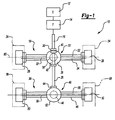
動力伝達系組立物が、総括的に図1の10に示されている。動力伝達系組立物10は、この技術分野で周知のように駆動軸16を駆動するエンジン12と変速機14を備えている。駆動軸16は、タンデム車軸装置の前輪駆動車軸18と入力部20において連結されている。前輪駆動車軸18は、キャリヤ22、車軸外管24、及び車軸外管24の対向する両端に位置し左右に間隔を空けて置かれた一対の車輪端部26を備えている。キャリヤ22は、キャリヤ収納箱28、及び一対の車軸32を駆動するよう作動可能状態で連結された差動装置組立物30を備えている。車軸32は、この技術分野で周知のように、タイヤ34を支持する車輪端部26を駆動する。
【0017】
タンデム車軸装置は、同じく前輪駆動車軸18に連結駆動軸38で連結された後輪駆動車軸36を備えている。前輪キャリヤ22内に置かれた車軸間差動装置(IAD)40は、入力部20において供給された駆動エネルギーを前輪18及び後輪36駆動車軸間に分配する。IAD40は、前輪駆動車軸18内で差動装置組立物30を駆動し、且つ駆動エネルギーを、後輪駆動車軸26に向かって、通し軸42経由で連結駆動軸28へ伝達する。連結駆動軸38は入力部44において後輪駆動車軸26に連結されている。
【0018】
後輪駆動車軸36は、キャリヤ46、車軸外管48、及び車軸外管48の対向する両端に位置しており左右に間隔を空けて置かれた一対の車輪端部50を備えている。キャリヤ46は、キャリヤ収納箱52、及び一対の車軸56を駆動するよう作動可能状態で連結された差動装置組立物54を備えている。車軸56は、上で吟味したように、タイヤ58を支持する車輪端部50を駆動する。
【0019】
タンデム装置における前輪駆動車軸用の従来のキャリヤ組立物60が、図2に示されている。キャリヤ組立物60は、前輪駆動車軸18内の歯車装置66と後輪駆動車軸36へ駆動エネルギーを伝達する通し軸68との間で駆動入力を分配する車軸間差動装置組立物(IAD)64への、入力部62を備えている。歯車装置66は、はす歯歯車装置であり、入力部62からの駆動エネルギーをピニオン歯車70と環状歯車72から成る歯車組立物まで伝達する。ピニオン70及び環状歯車72は、差動装置組立物74(図3に示す)を駆動し、それは次に車軸32を駆動する。はす歯歯車装置の環状72及びピニオン70歯車と組合された動作は、周知なので詳細は吟味しない。
【0020】
通し軸68は、ピニオン歯車回転軸78よりも垂直方向に高いところにある通し軸回転軸76を規定する。車軸32は、通し軸76及びピニオン歯車78回転軸に垂直な車軸回転軸80を規定する。図2に示した構造において、ピニオン歯車回転軸78は車軸回転軸80よりも垂直方向に低く、通し軸回転軸76は車軸回転軸80よりも垂直方向に高いところにある。はす歯歯車構造は、通し軸68に差動装置組立物74を通させるために必要である。この構造は、通し軸68を作動させるために十分な隙間が必要なので、差動装置全体の寸法を著しく制限する。
【0021】
図3に更に詳細に示すように、ピニオン歯車70は環状歯車72に形成された複数の環状歯車の歯84と噛み合っている複数のピニオン歯82を備えている。環状歯車72は、環状歯車の歯84が形成されている前面86と背面88とを備えている。ピニオン歯車70は、差動装置組立物74に作動可能状態で連結された環状歯車72を駆動する。
【0022】
差動装置組立物74は、第一半割デフケース90、第二半割デフケース92、及び差動歯車組立物94を備えている。第一90及び第二92半割デフケース歯差動歯車組立物94を支持する。差動歯車組立物94は、この技術分野で周知のように、四脚差動台98上に支持された四つ(4)の差動ピニオン歯車96(二つだけが示されている)を備えている。差動ピニオン歯車96は、車軸32にキーで固定された一対の側面歯車100と噛み合っている。差動装置組立物74の動作は周知なので詳細に吟味しない。
【0023】
環状歯車72は、複数の締め具104を用いて第一ボルト継手102において第二半割デフケース92に取り付けられる。第一90及び第二92半割デフケースは、複数の締め具110で第二ボルト継手108においてお互いに取り付けられ、デフケース分割線106を規定する。デフケース分割線106は、環状歯車72の表側部86に位置付けられている。半割デフケース90、92は、歯車頂点が互いの方向に向かって延伸するような従来の搭載構造を有する、一対の軸受112により支持されている。
【0024】
ピニオン歯車70は、はす歯歯車66aの一つの中心を貫通して延伸する軸部116に支えられた、ピニオン歯車頭部114を備えている。一対のピニオン軸受118が、キャリヤ収納箱120に対して相対的な回転をするよう、ピニオン歯車70を支持している。ピニオン軸受118は、ピニオン歯車頭部114より外側に搭載されており、はす歯歯車66aの対向する両側に置かれている。
【0025】
前輪駆動車軸18用の従来のキャリヤ組立物構造は、製造するのに費用がかかり且つ組み立てるのが困難である。更に、同じ収納空間内により強靭な諸部品設計物をという要求の増大に対して、これら従来構造は、現状の収納容器内において危機的状態にある部品をより強靭なものにするだけの余地を与えない。
【0026】
図4に示されている本発明は、部品数を著しく減らし、組立が容易で、従来構造より強靭な部品を提供するような、前輪駆動車軸18用の改善されたキャリヤ構造を提供する。縦連装置における前輪駆動車軸18用の改善されたキャリヤ組立物は、総括的に図4の130に示されている。キャリヤ組立物130は、駆動入力を前輪駆動車軸18と後輪駆動車軸36とに分配する車軸間差動装置組立物(IAD)134に連結された入力部132を備えている。IAD134は、通し軸138を介して前輪駆動車軸用の出力部136へ駆動入力を伝達する。
【0027】
IAD134は、差動台140、差動台140上に支持された複数のスパイダ歯車142、スパイダ歯車142に噛み合い嵌合している内側側面歯車144、及びスパイダ(spider)歯車142に噛み合い嵌合している外側側面歯車146を備えている。差動台140、スパイダ歯車142、及び内側144と外側146の側面歯車は、実質的にIAD収納箱148内に収納されている。収納箱148は、IAD用軸受組立物150に回転可能状態で支持されている。好ましくは、IAD用軸受組立物は単一円錐ころ軸受である。
【0028】
IAD134は、前輪駆動車軸18用の差動装置156に作動可能状態で連結している環状歯車154に噛み合い嵌合している、ピニオン歯車152を駆動する。ピニオン歯車152は、複数のピニオン歯車の歯162を持ったピニオン歯車頭部160を規定するような第一部品158を備えた二分割設計である。第一部品158は、ピニオン歯車頭部160からIAD134に向かって外向きに延伸する中空鞘部164を備えている。ピニオン歯車152は、内端部170、外端部172、および中央鍔部174を有する中空ピニオン支持軸168を規定する第二部品166を備えている。二つの部品158、166は、少なくとも一つの締め付け部品176で締め付けられるのが好ましいが、その他の接続部品も使用できよう。好ましくは、締め付け部品176は第二部品166に螺子切りされたナットである。
【0029】
第二部品168は、ピニオン歯車頭部160を越えて内側へ延伸している内端部170を持つ、中空鞘部164を貫通して延伸している。外端部172は、IAD134内に延伸し、逆荷重分担をさせるようにIAD軸受組立物150にスラスト荷重を負荷する。通し軸138は、通し軸138とピニオン歯車152が共通の軸178の周りを回転するように、中空ピニオン支持軸168を貫通して延伸している。この構造の一利点は、組立物に供給油を強制貫流するための別個のポンプ機構に対する必要性が排除されることである。
【0030】
中空鞘部164の末端部180は、中央鍔部174に突き当てられ、第一158及び第二部品を互いに相対的に適切な位置に配置させる。好ましい実施態様において、通し軸138の外端部182は、IAD134の外側側面歯車146と一緒に回転するよう固定され、ピニオン歯車152の第二部品166は、内側側面歯車144と一緒に回転するよう固定される。好ましくは、内側側面歯車144は、中央鍔部174に近接した中央部において、第二部品166の外面にキーで固定される。通し軸138は、通し軸138と第二部品166との間で独立した回転が許されるように、第二部品166を貫通して延伸している。キャリヤ組立物130は、内側側面歯車144、ピニオン歯車152、及び通し軸138を同じ速度で回転させるよう一緒に選択的に固定するための、184で一般的に示した差動装置固定用組立物を時に応じて備えることがある。
【0031】
ピニオン歯車152は、内側軸受186と外側軸受188により回転可能状態で支持されている。内側186及び外側188軸受は、ビニオン歯車頭部160の対向する両側に配置されている。内側軸受186は、第二部品166とキャリヤ収納箱部材190との間に支持されており、外側軸受188は、第一部品158とキャリヤ収納箱部材190との間に支持されている。外側軸受188は、第二部品166の中央鍔部174に突き当てられている。好ましくは、内側及び外側軸受186、188は、単一円錐ころ軸受である。下に詳しく吟味されているが、車軸中心線に関してピニオンの位置を上げたので、外側軸受188は寸法が内側軸受186より大きくなっている。
【0032】
軸受予荷重スペーサ192がピニオン歯車頭部160と内側軸受186の間に配置される。締め付け部品176は、内側軸受186に突き当てられ、望みの予荷重軸受力を負荷するように調節することが可能である。
【0033】
好ましい実施態様において、ピニオン歯車152の第二部品166の外端部は、外側側面歯車146に突き当てられスラスト荷重をIAD軸受組立物150に負荷する。このことは、IAD軸受組立物150に逆荷重を分担させ、翻って、内側軸受186を環状歯車154が避けて通れるよう十分小さなものにさせる。
【0034】
差動装置組立物156は、第一半割デフケース194、第二半割デフケース196、及び差動歯車組立物を備えている。第一194及び第二196半割デフケースは、差動歯車組立物を支持している。この技術分野で周知のように、差動歯車組立物は、四脚差動台200上に支持された、四つ(4)の差動ピニオン歯車198(二つだけ示されている)を備えている。差動ピニオン歯車198は、車軸32にキーで固定された一対の側面歯車202と噛み合っている。
【0035】
環状歯車154は、背面204及び、複数の環状歯車の歯208が形成された前面206を備えている。ピニオン歯車の歯162は、環状歯車の歯208と噛み合い差動装置組立物156を駆動する。第一194及び第二196半割デフケースは、互いに取り付けられ、環状歯車154の背面204に配置されたデフケース分割線210を規定する。環状歯車154、第一半割デフケース194、及び第二半割デフケース196は、複数の締め具214によって、単一ボルト継手212において全て一緒に接続されている。
【0036】
環状歯車154の背後におけるデフケース分割線210の移動が、半割ケース194、196に対する環状歯車154同様、両半割ケース194、196を同じ締め具で一緒に保持できるようにしている。これはボルト継手の数を二つから一つに減らす。
【0037】
この差動装置組立物構造の一つの利点は、従来構造によって規定される収納空間内に、より大きな差動装置部品を用いることが出来ることである。本発明の構造においては、従来構造におけるように、デフケースの直径がピニオン歯車の近接によって制限されることはない。従って、デフケース部品及び伝導装置の寸法は大きくすることができ、強靭性を増加させる。
【0038】
差動装置組立物156は、少なくとも一つの円錐ころ軸受216によってキャリヤ組立物130内において回転可能状態で支持されている。改善されたデフケース構造は、軸受216が逆構造において搭載されることを可能にする。軸受216は、環状歯車154の背面204から外側に延伸する方向において互いに発散するような軸受頂点を規定する、複数のローラー218を備えている。この逆軸受構造は、安定性を増し、スラスト螺子の必要性を低減する。
【0039】
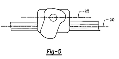
上で吟味したように、通し軸138は、IAD134の外側側面歯車146に固定された第一端部182と、出力部136に連結された第二端部220とを具備している。通し軸138の第二端部220は、単一円錐ころ軸受222で支持されることが好ましい。円錐ころ軸受222は、通し軸138とキャリヤ収納箱部材190との間に配置されている。キャリヤ収納箱部材190は、この技術分野で周知のように、車軸収納箱部材224に締め付けられている。キャリヤ搭載鋳物は、キャリヤ組立物130の鉢状物側まで延伸しており、収納箱224内に位置する突起部226を備えている。突起部226は、軸受222を支持し且つ収納箱224内における別個の軸受保持具部材の必要性を排除する。この構造は亦、キャリヤ組立物130内において、通し軸138の改善された芯合わせを提供する。
【0040】
ピニオン歯車152の入力部は、図5に示されたピニオン中心線228を規定し、それは車軸32により規定される車軸中心線230より垂直方向に高いところにある。この構造において、駆動荷重は、従来構造で為されたようにピニオン歯車152を押す、というよりはむしろピニオン歯車152を引っ張る。IAD134の外側側面歯車146に突き当てられている二部品ピニオン歯車152の使用は、IAD軸受組立物150との逆荷重分担を可能にする。更にこの構造は、内側ピニオン軸受組立物寸法を減少させる。
【0041】
本発明は、従来収納容器内に更に強靭な部品構造を備えるような、タンデム装置における前輪駆動車軸用の、改善されたキャリヤ組立物を提供する。更にこのキャリヤ構造は、必要な部品の全数を減少させ、製造するのにより少ない費用しか掛からない。本発明の好ましい実施態様が開示されたが、本発明の範囲内においてある種の諸修正がなされるであろうことを、当業者は認識するであろう。この理由において、以下の特許請求の範囲は、本発明の真の範囲と内容とを決定するように吟味されるべきである。
【図面の簡単な説明】
【図1】タンデム駆動車軸装置用の動力伝達系組立物の概略平面図である。
【図2】先行技術によるタンデム車軸装置における前輪駆動車軸用キャリヤ組立物の断面側面図である。
【図3】図2のキャリヤ組立物の断面上面図である。
【図4】本発明を取り入れたタンデム車軸装置における前輪駆動車軸用キャリヤ組立物の断面上面図である。
【図5】前輪駆動車軸に取り入れられた図4のキャリヤ組立物の概略正面図である。[0001]
TECHNICAL FIELD OF THE INVENTION
(Background of the Invention)
The present invention relates to a unique carrier, axle differential, and inter-axle differential assembly structure for a tandem drive axle.
[0002]
[Prior art]
The tandem drive axle assembly includes a front wheel drive axle and a rear drive axle interconnected by a drive shaft. The single drive input is operatively connected to a front wheel drive axle including an inter-axle differential (IAD). The IAD distributes a driving force from an input unit between a front wheel and a rear wheel drive axle. The through shaft interconnects the drive shaft and the IAD that provide input to the rear wheel drive axle.
[0003]
The front and rear wheel drive axles are each provided with a carrier having a differential gear assembly to prevent the wheels from skidding during a turning operation. When a car travels along a straight road, both wheels on the drive axle will rotate at essentially the same speed. However, during a turning operation, the outer wheel of rotation must travel a longer distance than the inner wheel of rotation, which means that the outer wheel of rotation must rotate at a faster speed than the inner wheel of rotation. Means not A differential gear assembly is needed to allow for this wheel speed difference.
[0004]
Conventionally, a front wheel drive axle carrier includes a helical gearing that transmits driving force from an input in an IAD to an annular and pinion gearing operatively connected to a differential assembly. The differential assembly includes a first half differential case, a second half differential case, and a differential gear unit. The ring gear is bolted to one of the half cases to define a first bolted joint, and the first and second half cases are bolted together to define a second bolted joint.
[0005]
The helical gear structure is also required to pass the through shaft through the differential case assembly. This structure significantly limits the overall size of the differential as there is sufficient clearance to operate the through shaft. The through shaft is mounted within the front axle outer tube by a pair of bearings supported by separate retainer members bolted to the storage box.
[0006]
Conventional differential case and through shaft configurations are expensive to manufacture and difficult to assemble. In addition, in response to the increasing demands of users to supply more robust designs in the same storage space, these conventional structures make parts in crisis in the current storage container stronger. Don't give room for it. In addition, structures consisting of IADs and helical gears often require a separate pump mechanism to force the feed through the assembly. This additional pumping mechanism is undesirable because it adds cost and adds weight to the assembly.
[0007]
Accordingly, it is desirable to provide an improved front wheel drive carrier having a differential assembly that accommodates more robust components within the same storage container. Further, to provide a simplified carrier and through-shaft structure that overcomes the deficiencies of the art outlined above, while reducing the total number of required parts and requiring less cost to manufacture. Is desired.
[0008]
[Means for Solving the Problems]
(Summary of the Invention)
The tandem axle device comprises a front wheel drive axle and a rear wheel drive axle connected together by a connecting drive shaft. The front wheel drive axle includes a front wheel carrier assembly coupled to the input of the vehicle for driving a pair of front axles. An inter-axle differential (IAD) in the front wheel carrier assembly distributes driving force between the front and rear wheel drive axles. The through-shaft is connected at one end to the IAD and at an opposing end to a connection drive shaft to the output. The coupling drive shaft is coupled to drive a rear wheel carrier assembly that drives the rear pair of axles.
[0009]
The front wheel carrier assembly includes a front wheel drive gear assembly operably connected to a pair of front axles. The front wheel drive gear assembly includes a pinion gear, an annular gear, and a front wheel differential assembly. The differential assembly includes first and second half differential cases that can be mounted at a case interface defining a case parting line. The differential assembly also includes a differential gear assembly supported by the first and second half differential cases, with the gear assembly operatively connected to drive the front pair of axles. It has. The ring gear is mounted on a half differential case. The IAD provides drive to a pinion gear that meshes with the ring gear and drives the axle through a differential gear assembly.
[0010]
The IAD includes a differential table, a plurality of spider gears supported by the differential table, an inner side gear meshing with the spider gear, and an outer side gear meshing with the spider gear. The differential stand, spider gear, and inner and outer side gears are substantially contained within the IAD storage box. The storage box is rotatably supported on the IAD gear assembly. The pinion gear is mounted for rotation with the inner side gear and provides drive input to the front wheel drive axle. The through shaft is keyed to rotate with the outer side gear and provides drive input to the rear wheel drive axle.
[0011]
In a preferred embodiment, the pinion gear comprises a first part defining a pinion gear head and a second part defining a hollow pinion support shaft extending into the IAD. The through shaft extends through the hollow pinion support shaft such that the pinion gear and the through shaft rotate about a common axis. The pinion support shaft extends into the inter-axle differential assembly to apply a thrust load to the inner end supporting the first component and to the axle differential bearing assembly to provide reverse load sharing. Outer end portion.
[0012]
In one disclosed embodiment, the pinion gear is supported by a pair of bearings comprising an inner bearing and an outer bearing located on opposite sides of the pinion gear head. The outer bearing is supported on the first part and the inner bearing is supported on the second part. Preferably, the inner and outer bearings are tapered roller bearings.
[0013]
The first part of the pinion gear has a hollow shaft sheath extending outward in a direction from the pinion gear head toward the IAD. A second part defining a pinion support shaft extends through the hollow shaft sheath. The inner end of the pinion support shaft extends beyond the pinion gear head to support the inner bearing. The pinion support shaft has a central flange that abuts against the end of the hollow shaft sheath. Preferably, the pinion support shaft is fixed for rotation with the inner side gear at a central portion between the inner and outer ends and near the central collar.
[0014]
Preferably, the outer end of the pinion support shaft extends into the IAD to abut the outer side gear. Therefore, the thrust load is applied to the IAD bearing assembly via the outer side gear. Further, the through shaft extends beyond the pinion support shaft and is fixed for rotation with the outer side gear.
[0015]
The present invention provides a front wheel drive in a tandem axle system that provides a more robust design within a conventional size storage envelope, significantly reduces the number of parts required, and improves and simplifies assembly. Provide an improved carrier and inter-axle differential structure for axles. These and other features of the present invention will be best understood from the following specification and drawings, which are a brief description thereof.
[0016]
BEST MODE FOR CARRYING OUT THE INVENTION
(Detailed description of preferred embodiments)
The powertrain assembly is shown generally at 10 in FIG. The
[0017]
The tandem axle device also includes a rear wheel drive axle 36 connected to the front wheel drive axle 18 by a
[0018]
The rear wheel drive axle 36 includes a
[0019]
A
[0020]
The through shaft 68 defines a through shaft rotation shaft 76 that is vertically higher than the pinion
[0021]
As shown in more detail in FIG. 3, the
[0022]
The
[0023]
The
[0024]
The
[0025]
Conventional carrier assembly structures for front wheel drive axles 18 are expensive to manufacture and difficult to assemble. Furthermore, in response to the increasing demand for more robust component designs in the same storage space, these conventional structures have room for more robust components in crisis in the current storage container. Do not give.
[0026]
The present invention shown in FIG. 4 provides an improved carrier structure for a front wheel drive axle 18 that significantly reduces the number of parts, is easier to assemble, and provides more robust parts than conventional structures. The improved carrier assembly for the front wheel drive axle 18 in a tandem arrangement is shown generally at 130 in FIG. The
[0027]
The
[0028]
The
[0029]
The
[0030]
The
[0031]
The
[0032]
A bearing
[0033]
In a preferred embodiment, the outer end of the
[0034]
The
[0035]
The
[0036]
The movement of the differential
[0037]
One advantage of this differential assembly structure is that larger differential components can be used within the storage space defined by the conventional structure. In the structure of the present invention, the diameter of the differential case is not limited by the proximity of the pinion gear as in the conventional structure. Thus, the dimensions of the differential case components and the transmission can be increased, increasing the toughness.
[0038]
The
[0039]
As discussed above, the through
[0040]
The input of
[0041]
The present invention provides an improved carrier assembly for a front-wheel drive axle in a tandem device, which conventionally provides a more robust component structure within the storage bin. Furthermore, this carrier structure reduces the total number of parts required and costs less to manufacture. While a preferred embodiment of the invention has been disclosed, those skilled in the art will recognize that certain modifications will occur within the scope of the invention. For this reason, the following claims should be studied to determine the true scope and content of this invention.
[Brief description of the drawings]
FIG. 1 is a schematic plan view of a power transmission system assembly for a tandem drive axle device.
FIG. 2 is a cross-sectional side view of a carrier assembly for a front wheel drive axle in a tandem axle device according to the prior art.
3 is a cross-sectional top view of the carrier assembly of FIG.
FIG. 4 is a cross-sectional top view of a front wheel drive axle carrier assembly in a tandem axle apparatus incorporating the present invention.
5 is a schematic front view of the carrier assembly of FIG. 4 incorporated into a front wheel drive axle.
Claims (25)
入力部;
前記入力部に作動可能状態で連結され、且つ車軸間差動装置用軸受組立物上に回転可能状態で支持された車軸間差動装置;
ピニオン歯車回転軸の周りを回転するよう前記車軸間差動装置に作動可能状態で連結されたピニオン歯車、前記ピニオン歯車はピニオン歯車頭部を規定する第一部品と中空中央部を有するピニオン軸を規定する第二部品とを具備し、前記ピニオン軸は前記第一部品を支持するための内端部とスラスト荷重を前記車軸間差動装置用軸受組立物に負荷するための前記車軸間差動装置組立物内に延伸した外端部とを具備している;
通し軸回転軸の周りを回転するよう前記第二部品の前記中空中央部を貫通して延伸している通し軸;及び
後輪駆動車軸へ駆動力を伝達するよう前記通し軸に作動可能状態で連結された出力部;
から構成される組立物。A carrier assembly for a front wheel drive axle of a tandem axle device, comprising:
Input section;
An inter-axle differential operatively connected to the input and rotatably supported on the inter-axle differential bearing assembly;
A pinion gear operably connected to the inter-axle differential to rotate about a pinion gear rotation axis, the pinion gear comprising a pinion shaft having a first part defining a pinion gear head and a hollow central portion; A second component defining the first component, wherein the pinion shaft has an inner end for supporting the first component and the inter-axle differential for applying a thrust load to the bearing assembly for an inter-axle differential. An outer end extending into the device assembly;
A through shaft extending through the hollow center portion of the second part to rotate about a through shaft rotation axis; and operable to the through shaft to transmit driving force to a rear wheel drive axle. Connected output;
An assembly consisting of:
入力部;
前記入力部に作動可能状態で連結され、且つ車軸間差動装置用軸受組立物上に回転可能状態で支持された車軸間差動装置、前記車軸間差動装置は差動台、前記差動台に支持された複数のスパイダー歯車、前記スパイダー歯車と噛み合い嵌合している内側側面歯車、及び前記スパイダー歯車と噛み合い嵌合している外側側面歯車を備えている;
ピニオン歯車回転軸の周りを回転するよう前記車軸間差動装置に作動可能状態で連結されたピニオン歯車、前記ピニオン歯車はピニオン歯車頭部を規定する第一部品と中空中央部を有するピニオン軸を規定する第二部品とを具備し、前記ピニオン軸は、前記内側側面歯車と一緒に回転するよう固定されており、且つ前記第一部品を支持するための内端部とスラスト荷重を前記車軸間差動装置用軸受組立物に負荷するよう前記外側側面歯車と突き当て嵌合している外端部とを具備している;
前記第二部品の前記中空中央部を貫通して延伸しており、且つ前記外側側面歯車と一緒に回転するよう固定された一端部を具備する通し軸;及び
後輪駆動車軸へ駆動力を伝達するよう前記通し軸に作動可能状態で連結された出力部;
から構成される組立物。A carrier assembly for a front wheel drive axle of a tandem axle device, comprising:
Input section;
An axle differential that is operatively connected to the input and rotatably supported on a bearing assembly for an axle differential, the axle differential is a differential table, the differential A plurality of spider gears supported on the platform, an inner side gear meshingly engaged with the spider gear, and an outer side gear meshingly engaged with the spider gear;
A pinion gear operably connected to the inter-axle differential to rotate about a pinion gear rotation axis, the pinion gear comprising a pinion shaft having a first part defining a pinion gear head and a hollow central portion; A second part defining the first part, wherein the pinion shaft is fixed to rotate together with the inside side gear, and an inner end for supporting the first part and a thrust load between the axle. An outer end in abutting engagement with said outer side gear to load a differential bearing assembly;
A through shaft extending through the hollow central portion of the second part and having one end fixed to rotate with the outer side gear; and transmitting a driving force to a rear wheel drive axle. An output operably connected to the through shaft to:
An assembly consisting of:
Applications Claiming Priority (1)
| Application Number | Priority Date | Filing Date | Title |
|---|---|---|---|
| US10/127,584 US6648788B1 (en) | 2002-04-26 | 2002-04-26 | Forward carrier assembly for tandem axle |
Publications (2)
| Publication Number | Publication Date |
|---|---|
| JP2004001726A true JP2004001726A (en) | 2004-01-08 |
| JP2004001726A5 JP2004001726A5 (en) | 2005-09-08 |
Family
ID=29248434
Family Applications (1)
| Application Number | Title | Priority Date | Filing Date |
|---|---|---|---|
| JP2003112318A Pending JP2004001726A (en) | 2002-04-26 | 2003-04-17 | Front wheel carrier assembly for tandem axle |
Country Status (2)
| Country | Link |
|---|---|
| US (1) | US6648788B1 (en) |
| JP (1) | JP2004001726A (en) |
Families Citing this family (23)
| Publication number | Priority date | Publication date | Assignee | Title |
|---|---|---|---|---|
| US6764676B1 (en) * | 1998-08-24 | 2004-07-20 | Pfizer Inc. | Compositions and methods for protecting animals from lentivirus-associated disease such as feline immunodeficiency virus |
| US6840882B2 (en) * | 2002-10-23 | 2005-01-11 | Arvinmeritor Technology, Llc | Inter-axle differential assembly for a tandem drive axle set |
| US7211017B2 (en) * | 2002-11-06 | 2007-05-01 | Dana Corporation | Inter-axle differential lock shift mechanism |
| US6918851B2 (en) * | 2002-11-06 | 2005-07-19 | Dana Corporation | Concentric shift system for engaging an interaxle differential lock |
| US7500934B2 (en) * | 2003-11-06 | 2009-03-10 | Dana Heavy Vehicle Systems Group, Llc | Drive system and method of assembly thereof |
| FR2866684B1 (en) * | 2004-02-24 | 2007-05-11 | Renault Vehicules Ind | MECHANICAL ASSEMBLY ADAPTATION |
| US7690449B2 (en) * | 2004-05-10 | 2010-04-06 | Dana Heavy Vehicle Systems Group, Llc | Output yoke shaft and assembly |
| US20070117672A1 (en) * | 2005-11-18 | 2007-05-24 | Elvins Francis J | Tandem axle system |
| GB0601716D0 (en) * | 2006-01-27 | 2006-03-08 | Meritor Heavy Vehicle Sys Ltd | Differential gear casing and method |
| DE102008015227A1 (en) | 2008-03-20 | 2009-03-19 | Daimler Ag | Drive train for motor vehicle i.e. commercial motor vehicle, has clutch mechanism aiding half shafts, where clutch mechanism is coupleable and decoupleable from drive shaft and formed as differential gear with unequal torque distribution |
| CN101905651A (en) * | 2009-06-07 | 2010-12-08 | 周殿玺 | Differential-twist driving device |
| US9453570B2 (en) * | 2009-12-07 | 2016-09-27 | Arvinmeritor Technology, Llc | Differential lock with assisted return |
| US20120021863A1 (en) | 2010-07-22 | 2012-01-26 | Wagner Yukio Hirao | Hypoid gear set for drive axle |
| WO2013032477A1 (en) * | 2011-08-31 | 2013-03-07 | Mack Trucks, Inc. | A forward carrier assembly with a reversible inter-axle differential for a tadem axle vehicle, a powertrain for a tandem axle vehicle, and a tandem axle vehicle |
| CN104175892A (en) * | 2013-05-23 | 2014-12-03 | 陕西汉德车桥有限公司 | Commercial vehicle main speed reducer assembly and single-stage speed-reducing driving axle |
| US9457654B2 (en) | 2015-01-20 | 2016-10-04 | Arvinmeritor Technology, Llc | Drive axle system |
| CN104626978B (en) * | 2015-03-12 | 2017-03-01 | 济南大学 | Vehicle active-type differential gearing vehicle bridge |
| US10315515B2 (en) * | 2016-08-05 | 2019-06-11 | Honda Motor Co., Ltd. | Power transfer unit pinion shaft and propeller shaft coupling member for a vehicle, and methods of use and manufacture thereof |
| US10011174B2 (en) | 2016-11-04 | 2018-07-03 | Dana Heavy Vehicle Systems Group, Llc | Tandem axle gearing arrangement |
| US10208846B2 (en) | 2017-03-10 | 2019-02-19 | Arvinmeritor Technology, Llc | Axle assembly having a drive pinion support bearing and a method of assembly |
| US10539218B2 (en) * | 2017-08-23 | 2020-01-21 | Arvinmeritor Technology, Llc | Axle assembly having a drive pinion assembly |
| US10703202B2 (en) * | 2018-02-12 | 2020-07-07 | Arvinmeritor Technology, Llc | Drive axle assembly with clutch collar |
| US11808342B2 (en) | 2022-02-08 | 2023-11-07 | Dana Automotive Systems Group, Llc | Differential carrier |
Family Cites Families (8)
| Publication number | Priority date | Publication date | Assignee | Title |
|---|---|---|---|---|
| USRE25269E (en) | 1962-10-23 | Axle mechanism | ||
| US2693244A (en) * | 1950-06-15 | 1954-11-02 | Rockwell Spring & Axle Co | Multiwheeler with angle drive |
| US2699075A (en) * | 1951-08-16 | 1955-01-11 | Rockwell Spring & Axle Co | Vehicle drive mechanism |
| US3532183A (en) * | 1968-02-26 | 1970-10-06 | Clark Equipment Co | Lubrication system for a differential |
| US3887037A (en) * | 1974-03-20 | 1975-06-03 | Clark Equipment Co | Lubrication system for differentials |
| US4050534A (en) | 1975-02-13 | 1977-09-27 | Eaton Corporation | Drive axle system useable in 6 × 6 vehicle |
| US5860889A (en) | 1995-12-01 | 1999-01-19 | Dana Corporation | Tandem forward rear axle lockout |
| US6200240B1 (en) * | 1999-02-11 | 2001-03-13 | Meritor Heavy Vehicle Systems, Llc | Inter-axle differential assembly for a tandem drive axle set |
-
2002
- 2002-04-26 US US10/127,584 patent/US6648788B1/en not_active Expired - Lifetime
-
2003
- 2003-04-17 JP JP2003112318A patent/JP2004001726A/en active Pending
Also Published As
| Publication number | Publication date |
|---|---|
| US6648788B1 (en) | 2003-11-18 |
| US20030203783A1 (en) | 2003-10-30 |
Similar Documents
| Publication | Publication Date | Title |
|---|---|---|
| JP2004001726A (en) | Front wheel carrier assembly for tandem axle | |
| US6991571B2 (en) | Variable ratio drive system | |
| US7311631B2 (en) | Differential device and drive power transmission unit using the same | |
| US7350606B2 (en) | Double reduction electric drive wheel assembly | |
| US6886655B2 (en) | Vehicle wheel end assembly with double reduction gear set | |
| US20070251739A1 (en) | Electronic all-wheel drive module with overrunning clutch differential | |
| JPH01269745A (en) | Power transmission | |
| US9353847B2 (en) | Torque vectoring device | |
| JP6380444B2 (en) | Hybrid vehicles and vehicles | |
| JPWO2004092617A1 (en) | Support structure and gear mechanism provided with support structure | |
| WO2017050101A1 (en) | Power driving system and vehicle having same | |
| JP2626167B2 (en) | Transfer device for four-wheel drive vehicles | |
| US6689009B1 (en) | Compact differential assembly | |
| JP2626168B2 (en) | Transfer device for four-wheel drive vehicles | |
| JP2004155414A (en) | Inter-axle differential assembly for tandem driving axle set | |
| JP2004503435A (en) | Power distribution system for vehicles with uneven terrain | |
| WO2018034099A1 (en) | Vehicle driving device | |
| CN108071768A (en) | It is integrated with the differential carrier and its manufacturing method of transmission gear | |
| EP1481835A1 (en) | Forward carrier assembly for tandem axle | |
| CN106080039B (en) | Double drive rear axles of loading motorcycle | |
| JPH07156678A (en) | Power transmitting device | |
| JPS63251648A (en) | Differential device | |
| JPH0349766B2 (en) | ||
| JP2520584Y2 (en) | Through shaft for power transmission final reducer | |
| US7318785B2 (en) | Worm gear differential |
Legal Events
| Date | Code | Title | Description |
|---|---|---|---|
| A521 | Written amendment |
Free format text: JAPANESE INTERMEDIATE CODE: A523 Effective date: 20050322 |
|
| A621 | Written request for application examination |
Free format text: JAPANESE INTERMEDIATE CODE: A621 Effective date: 20050823 |
|
| A131 | Notification of reasons for refusal |
Free format text: JAPANESE INTERMEDIATE CODE: A131 Effective date: 20080304 |
|
| A02 | Decision of refusal |
Free format text: JAPANESE INTERMEDIATE CODE: A02 Effective date: 20080805 |