FR2708321A1 - Power unit - Google Patents
Power unit Download PDFInfo
- Publication number
- FR2708321A1 FR2708321A1 FR9309463A FR9309463A FR2708321A1 FR 2708321 A1 FR2708321 A1 FR 2708321A1 FR 9309463 A FR9309463 A FR 9309463A FR 9309463 A FR9309463 A FR 9309463A FR 2708321 A1 FR2708321 A1 FR 2708321A1
- Authority
- FR
- France
- Prior art keywords
- lever
- rod
- arm
- force
- axes
- Prior art date
- Legal status (The legal status is an assumption and is not a legal conclusion. Google has not performed a legal analysis and makes no representation as to the accuracy of the status listed.)
- Granted
Links
- 230000007246 mechanism Effects 0.000 claims abstract description 23
- 230000005540 biological transmission Effects 0.000 claims description 24
- 230000002787 reinforcement Effects 0.000 claims description 3
- 210000003205 muscle Anatomy 0.000 claims 1
- 230000033001 locomotion Effects 0.000 abstract description 9
- 238000004519 manufacturing process Methods 0.000 abstract description 3
- 230000005611 electricity Effects 0.000 abstract description 2
- 238000005461 lubrication Methods 0.000 description 17
- 230000003387 muscular Effects 0.000 description 3
- 230000000694 effects Effects 0.000 description 2
- 230000001360 synchronised effect Effects 0.000 description 2
- 238000002485 combustion reaction Methods 0.000 description 1
- 238000010276 construction Methods 0.000 description 1
- 230000008878 coupling Effects 0.000 description 1
- 238000010168 coupling process Methods 0.000 description 1
- 238000005859 coupling reaction Methods 0.000 description 1
- 230000001681 protective effect Effects 0.000 description 1
- 230000000630 rising effect Effects 0.000 description 1
Classifications
-
- F—MECHANICAL ENGINEERING; LIGHTING; HEATING; WEAPONS; BLASTING
- F16—ENGINEERING ELEMENTS AND UNITS; GENERAL MEASURES FOR PRODUCING AND MAINTAINING EFFECTIVE FUNCTIONING OF MACHINES OR INSTALLATIONS; THERMAL INSULATION IN GENERAL
- F16H—GEARING
- F16H21/00—Gearings comprising primarily only links or levers, with or without slides
- F16H21/10—Gearings comprising primarily only links or levers, with or without slides all movement being in, or parallel to, a single plane
- F16H21/16—Gearings comprising primarily only links or levers, with or without slides all movement being in, or parallel to, a single plane for interconverting rotary motion and reciprocating motion
- F16H21/18—Crank gearings; Eccentric gearings
Landscapes
- Engineering & Computer Science (AREA)
- General Engineering & Computer Science (AREA)
- Mechanical Engineering (AREA)
- Transmission Devices (AREA)
Abstract
Description
DESCRIPTION
La présente invention conceme un système mécanique à levier(s) permettant, à partir d'une force motrice ou de la force musculaire, d'en obtenir la multiplication par synchronisme des distances, des vitesses, des temps des deux moments d'un et plusieurs leviers.DESCRIPTION
The present invention relates to a mechanical system with lever (s) making it possible, starting from a motive force or from muscular force, to obtain the multiplication thereof by synchronism of the distances, speeds, times of the two moments of one and several levers.
Avec un levier sur un point d'appui fixe, on peut développer de la force, mais on ne peut en obtenir la multiplication parce que les distances, les vitesses, les temps des deux moments du levier (moment direct et moment inverse) sont inégaux.With a lever on a fixed fulcrum, one can develop force, but one cannot obtain its multiplication because the distances, the speeds, the times of the two moments of the lever (direct moment and opposite moment) are unequal .
Le système mécanique à leviers(s) logé dans un cadre permet de remédier à cet inconvénient en fixant le levier à un point d'appui mobile qui est un balancier suspendu au cadre par des suspentes. Le levier actionne un vilebrequin fixé sur deux paliers par l'intermédiaire de la bielle motrice. Le balancier est actionné par l'intermédiaire de la bielle du point d'appui actionnée par le vilebrequin. Le levier est actionné par l'intermédiaire de la bielle d'effort elle-même actionnée par une force motrice qui entraîne une roue dentée à laquelle elle est couplée par un axe. La roue dentée est fixée avec son arbre (arbre primaire) sur deux paliers. La force motrice et la roue dentée sont fixés à un cadre lui-même fixé au cadre du système mécanique à levier par des écrous. Le système mécanique à levier(s) entraîne, par la force motrice,
L'arbre secondaire par l'intermédiaire de la bielle de force actionnée par le vilebrequin.The mechanical system with levers (s) housed in a frame overcomes this drawback by fixing the lever to a mobile support point which is a pendulum suspended from the frame by lines. The lever actuates a crankshaft fixed on two bearings by means of the driving rod. The balance is actuated via the connecting rod of the fulcrum actuated by the crankshaft. The lever is actuated by means of the force rod itself actuated by a driving force which drives a toothed wheel to which it is coupled by an axis. The toothed wheel is fixed with its shaft (primary shaft) on two bearings. The driving force and the toothed wheel are fixed to a frame itself fixed to the frame of the mechanical lever system by nuts. The mechanical lever system (s) drives, by motive force,
The secondary shaft via the force rod actuated by the crankshaft.
L'arbre secondaire est entraîné par une roue à laquelle il est fixé qui est couplée à la bielle de force par un axe. L'arbre secondaire est fixé sur deux paliers à un cadre luimême fixé au cadre du système mécanique à levier par des écrous. L'ensemble constitue un groupe. Le groupe est fermé aux deux extrémités par deux plaques de protection fixées par des écrous. La force développée est exploitable par les cannelures de l'arbre secondaire.The secondary shaft is driven by a wheel to which it is attached which is coupled to the force rod by an axle. The secondary shaft is fixed on two bearings to a frame itself fixed to the frame of the mechanical lever system by nuts. The whole constitutes a group. The group is closed at both ends by two protective plates fixed by nuts. The force developed can be exploited by the splines of the secondary shaft.
Pour obtenir le synchronisme des distances, des vitesses, des temps, il faut que le levier en position haute soit à 45" de la perpendiculaire ; en position basse à 73" par rapport à la ligne des axes balancier-levier. Les distances, les vitesses, les temps des deux moments du levier (moment direct, moment inverse) sont en synchronisme donc égaux. To obtain the synchronism of the distances, speeds, times, the lever in the high position must be 45 "from the perpendicular; in the low position at 73" from the line of the balance-lever axes. The distances, the speeds, the times of the two moments of the lever (direct moment, opposite moment) are in synchronism therefore equal.
En actionnant le levier, on obtient quatre mouvements : un mouvement oscillatoire du balancier, deux mouvements alternatifs du levier (un mouvement alternatif du point d'effort, un mouvement alternatif du point de force), un mouvement de rotation du vilebrequin. Ces quatre mouvements constituent un cycle.By actuating the lever, four movements are obtained: an oscillating movement of the balance, two alternative movements of the lever (an alternative movement of the force point, an alternative movement of the force point), a rotation movement of the crankshaft. These four movements constitute a cycle.
L'équilibrage du système mécanique à levier(s) est un facteur important; I'équilibrage s'obtient à l'aide d'une masse d'équilibrage placée au point d'effort. II faut que l'ensemble du système mécanique puisse être mis en mouvement presque sans effort. Pour cela, on adapte en poids la masse en fonction de l'effort qu'il faut faire pour équilibrer l'ensemble du mécanisme. On obtient la multiplication de la force en couplant d'autres systèmes mécaniques à levier(s) au premier par l'intermédiaire de la bielle de transmission. On peut coupler autant de "systèmes mécanique à levier(s)" qu'il est nécessaire. Les "systèmes mécaniques à levier(s)" sont assemblés cadre contre cadre et fixés par des écrous. Le "groupe" ainsi formé est fixé au sol sur un socle ou sur un châssis par l'intermédiaire de pattes de fixation à l'aide d'écrous.Balancing the mechanical system with lever (s) is an important factor; Balancing is obtained using a balancing mass placed at the point of effort. It is necessary that the whole mechanical system can be set in motion almost effortlessly. For this, we adapt the weight by weight depending on the effort that must be made to balance the entire mechanism. The multiplication of the force is obtained by coupling other mechanical systems with lever (s) to the first by means of the transmission rod. As many "mechanical lever systems" can be coupled as necessary. The "mechanical lever systems" are assembled frame against frame and fixed by nuts. The "group" thus formed is fixed to the ground on a base or on a chassis by means of fixing lugs using nuts.
On peut augmenter la force développée par chaque système mécanique à levier(s) en leur adaptant un "volant-masse" d'entraînement actionné par l'intermédiaire de la bielle du "volant-masse" elle-même actionnée par le vilebrequin.We can increase the force developed by each mechanical system with lever (s) by adapting a "flywheel-mass" drive actuated by means of the connecting rod of the "flywheel-mass" itself actuated by the crankshaft.
Le "volant-masse" d'entraînement est constitué d'un volant plus d'une masse incorporée au volant. La masse dans la phase descendante, par l'action de l'apesanteur, applique une force supplémentaire à la force développée par le levier.The drive "mass flywheel" consists of a flywheel plus a mass incorporated into the flywheel. The mass in the descending phase, by the action of weightlessness, applies an additional force to the force developed by the lever.
Dans la phase montante, la masse est entraînée par le volant ; on obtient un avantage mécanique. L'avantage mécanique, levier plus "volant-masse", est fonction de la dimension, du poids, de la vitesse de rotation du "volant-masse". Pour que la masse donne un avantage mécanique, il ne faut pas que sa vitesse de rotation circonférentielle dépasse 9,81 mètres seconde au carré.In the rising phase, the mass is driven by the flywheel; a mechanical advantage is obtained. The mechanical advantage, lever plus "flywheel-mass", is a function of the size, weight and speed of rotation of the "flywheel-mass". For the mass to give a mechanical advantage, its circumferential speed of rotation must not exceed 9.81 square meters per second.
La force développée par un ou plusieurs "systèmes mécaniques à levier(s)", avec ou sans "volant-masse" d'entraînement, est exploitable mécaniquement par l'intermédiaire de l'arbre secondaire.The force developed by one or more "mechanical lever systems", with or without a drive-mass flywheel, can be exploited mechanically via the secondary shaft.
Les leviers peuvent être de plusieurs forces : force deux F2, force trois F3, force quatre F4. Pour obtenir un levier de F2, il faut diviser en trois la distance entre le point d'effort et le point de force. Le point d'appui doit être à l'intersection du premier et du deuxième tiers en partant du point de force. The levers can be of several forces: force two F2, force three F3, force four F4. To obtain a lever of F2, it is necessary to divide in three the distance between the point of effort and the point of force. The fulcrum must be at the intersection of the first and second thirds starting from the point of force.
Pour obtenir un levier F3, il faut diviser en quatre la distance entre le point d'effort et le point de force. Le point d'appui doit être à l'intersection du premier et du deuxième quart en partant du point de force.To obtain a lever F3, it is necessary to divide by four the distance between the point of effort and the point of force. The fulcrum must be at the intersection of the first and the second quarter starting from the point of force.
Pour obtenir un levier F4, il faut diviser en cinq la distance entre le point d'effort et le point de force. Le point d'appui doit être à l'intersection du premier et du deuxième cinquième en partant du point de force.To obtain an F4 lever, divide the distance between the point of effort and the point of force by five. The fulcrum must be at the intersection of the first and second fifth starting from the point of force.
La valeur de la force initiale : F2 = 1 x 2 = valeur initiale
La valeur de la force initiale . F3 = 1 x 3 = valeur initiale
La valeur de la force initiale .' F4 = 1 x 4 = valeur initiale
Du fait que le levier est sur un point d'appui mobile, la résistance crée un effet de recul qui vient en butée au vilebrequin par l'intermédiaire de la bielle du point d'appui, et par effet d'opposition des forces on n'obtient qu'une valeur approchée.The value of the initial force: F2 = 1 x 2 = initial value
The value of the initial force. F3 = 1 x 3 = initial value
The value of the initial force. ' F4 = 1 x 4 = initial value
Because the lever is on a movable fulcrum, the resistance creates a recoil effect which comes into abutment at the crankshaft via the connecting rod of the fulcrum, and by force opposition effect on n 'obtains only an approximate value.
Avec un levier F2, en appliquant un effort de 1 au point d'effort, on développe une force de 1,5 au point de force : F2 = 1 x 1,5= valeur approchée.With a lever F2, by applying an effort of 1 at the point of effort, we develop a force of 1.5 at the point of force: F2 = 1 x 1.5 = approximate value.
Avec un levier F3, en appliquant un effort de 1 au point d'effort, on développe une force de 2 au point de force : F3 = 1 x 2 = valeur approchée.With a lever F3, by applying an effort of 1 at the point of effort, we develop a force of 2 at the point of force: F3 = 1 x 2 = approximate value.
Avec un levier F4, en appliquant un effort de 1 au point de force, on développe une force de 2,5 au point de force : F4 = 1 x 2,5 = valeur approchée.With a lever F4, by applying a force of 1 to the point of force, we develop a force of 2.5 at the point of force: F4 = 1 x 2.5 = approximate value.
Si on couple dix systèmes mécaniques à levier(s) synchronisés, on obtient avec une force motrice = 1 CH
Pour F2 (1,52)10=57,69 CH
Pour F3 (22)10 = 1.024 CH Pour F4 (2,52)10=9.535,92 CH
En poids 1 CH = 75 kg m/s F2. 57,69 x 75 = 4.326,75 kg m/s F3. 1.024 x 75 = 76.800 kg m/s F4. 9.535,92 x 75 = 715.194 kg m/s
Avec la force musculaire, en admettant qu'une personne développe une force de 10 kilos, on obtient:
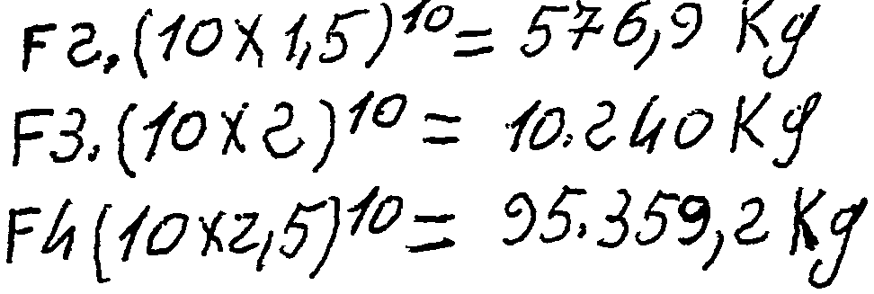
For F2 (1.52) 10 = 57.69 CH
For F3 (22) 10 = 1.024 CH For F4 (2.52) 10 = 9.535.92 CH
By weight 1 CH = 75 kg m / s F2. 57.69 x 75 = 4.326.75 kg m / s F3. 1.024 x 75 = 76.800 kg m / s F4. 9.535.92 x 75 = 715.194 kg m / s
With muscular strength, assuming that a person develops a force of 10 kilos, we obtain:
Les systèmes mécaniques à levier(s) peuvent être actionnés par une force motrice, moteurs à explosion, moteurs ou turbines à vapeur, par l'énergie hydraulique, éolienne, solaire, ou par la force musculaire.Mechanical lever systems can be actuated by motive power, internal combustion engines, steam engines or turbines, hydraulic, wind, solar, or muscular power.
On peut actionner les systèmes mécaniques à levier(s) à partir de différentes forces motrices 1 CH ou 10 CH, 50 CH, 100 CH etc. Les systèmes mécaniques à levier(s) peuvent être fabriqués du plus petit au plus grand qui soit fabriquable.Mechanical lever systems can be operated from different driving forces 1 CH or 10 CH, 50 CH, 100 CH etc. Mechanical lever systems can be manufactured from the smallest to the largest that can be manufactured.
Les dessins se trouvant en annexe illustrent l'invention.The drawings in the appendix illustrate the invention.
Ils se composent,'
FIGURE 1: bras de levier (1); fourches (2) (3); moyeux (4) (5); canaux de graissage (6) (7) (9) (11); moyeu du point d'appui (8); moyeu du point d'effort (10); axe (12); coussinets (13) (16); canaux de graissage (14) (15); axe du point d'appui (17); coussinet (18); canal de graissage (19); axe du point d'effort (20); coussinet (21); canal de graissage (22).They consist, '
FIGURE 1: lever arm (1); forks (2) (3); hubs (4) (5); lubrication channels (6) (7) (9) (11); hub of the fulcrum (8); point of effort hub (10); axis (12); pads (13) (16); lubrication channels (14) (15); axis of the fulcrum (17); bearing (18); lubrication channel (19); axis of the stress point (20); bearing (21); lubrication channel (22).
FIGURE 2 vue en coupe du levier:
Bras de levier (1): fourches (2) (3); moyeux (4) (5); moyeu du point d'appui (8); moyeu du point d'effort (10).FIGURE 2 sectional view of the lever:
Lever arm (1): forks (2) (3); hubs (4) (5); hub of the fulcrum (8); point of effort hub (10).
FIGURE 3 : bras du balancier (23); moyeux (24) (26); canaux de graissage (25) (27) (29); coussinet (28).FIGURE 3: pendulum arm (23); hubs (24) (26); lubrication channels (25) (27) (29); bearing (28).
FIGURE 4 vue en coupe du balancier:
Bras de balancier (23); moyeux (24) (26).FIGURE 4 sectional view of the pendulum:
Balance arm (23); hubs (24) (26).
FIGURE 5 : bras de la bielle du point d'appui (30); moyeux (31) (33); coussinets (35) (37); canaux de graissage (32) (34) (36) (38).FIGURE 5: arm of the connecting rod of the fulcrum (30); hubs (31) (33); pads (35) (37); lubrication channels (32) (34) (36) (38).
FIGURE 6 vue en coupe de la bielle du point d'appui:
Bras de la bielle du point d'appui (30) moyeux (31) (32).FIGURE 6 sectional view of the connecting rod of the fulcrum:
Arm of the connecting rod of the fulcrum (30) hubs (31) (32).
FIGURE 7 : bras de la bielle motrice (39); moyeu (40); pied de la bielle (44); chapeau du pied de la bielle (45); logements d'écrous filetés (46) (48); écrous (49) (50); demicoussinets (51) (52); canaux de graissage (41) (46) (43) (53). FIGURE 7: arm of the driving rod (39); hub (40); foot of the connecting rod (44); connecting rod cap (45); threaded nut housings (46) (48); nuts (49) (50); half-pads (51) (52); lubrication channels (41) (46) (43) (53).
FIGURE 8 vue en coupe de la bielle motrice:
Bras de la bielle motrice (39); moyeu (40); pied de la bielle (44); chapeau du pied de la bielle (45); logements d'écrous filetage (47) (48).FIGURE 8 sectional view of the driving rod:
Arm of the connecting rod (39); hub (40); foot of the connecting rod (44); connecting rod cap (45); thread nut housings (47) (48).
FIGURE 9 vue de côté de l'assemblage pied de la bielle, chapeau du pied de la bielle:
Bras de la bielle motrice (39); pied de la bielle (44); chapeau du pied de la bielle (45); canaux de graissage (46) (53); logements filetés d'écrous (47) (48) (54) (55); écrous (49) (50); demi-coussinets (51) (52); maneton (84).FIGURE 9 side view of the connecting rod foot assembly, connecting rod foot cap:
Arm of the connecting rod (39); foot of the connecting rod (44); connecting rod cap (45); lubrication channels (46) (53); nut threaded housings (47) (48) (54) (55); nuts (49) (50); half-bearings (51) (52); crankpin (84).
FIGURE 10 vue en coupe de côté : pied de la bielle (44); chapeau du pied de la bielle (45); canaux de graissage (46) (53); logements filetés d'écrous (47) (48); demicoussinets (51) (52); logement du maneton (84).FIGURE 10 side section view: foot of the connecting rod (44); connecting rod cap (45); lubrication channels (46) (53); nut threaded housings (47) (48); half-pads (51) (52); crankpin housing (84).
FIGURE 11: bras de la bielle d'effort (56); moyeux (57) (59); coussinets (61) (63); canaux de graissage (58) (60) (62) (64).FIGURE 11: arm of the force rod (56); hubs (57) (59); pads (61) (63); lubrication channels (58) (60) (62) (64).
FIGURE 12 vue en coupe de la bielle d'effort:
Bras de la bielle d'effort (56); moyeux (57) (59).FIGURE 12 sectional view of the force rod:
Force rod arm (56); hubs (57) (59).
FIGURE 13 : bras de la bielle du "volant-masse" (61); moyeux (62) (64); coussinets (66) (68); canaux de graissage (63) (65) (67) (69).FIGURE 13: arm of the connecting rod of the "mass flywheel" (61); hubs (62) (64); pads (66) (68); lubrication channels (63) (65) (67) (69).
FIGURE 14 : bras de la bielle du "volant-masse" (61); moyeux (62) (64).FIGURE 14: arm of the connecting rod of the "mass flywheel" (61); hubs (62) (64).
FIGURE 15 : bras de la bielle de force (70); moyeux (71) (73); coussinets (75) (77); canaux de graissage (72) (74) (76) (78).FIGURE 15: arm of the force rod (70); hubs (71) (73); pads (75) (77); lubrication channels (72) (74) (76) (78).
FIGURE 16 vue en coupe de la bielle de force: bras de la bielle de force (70); moyeux (71) (73).FIGURE 16 sectional view of the force rod: arm of the force rod (70); hubs (71) (73).
FIGURE 17 détails du système de graissage:
Axe (79); coussinet (80); moyeu (81); canal de graissage (82).FIGURE 17 details of the lubrication system:
Axis (79); bearing (80); hub (81); lubrication channel (82).
FIGURE 18 : vilebrequin bras primaire du vilebrequin (83); maneton de la bielle motrice (84); bras secondaire du vilebrequin (87); maneton des bielles, du point d'appui et du "volant-masse" (89); manetons de palier (85) (86); bras de force (88); axe de la bielle transmission (91); masse d'équilibrage (90).FIGURE 18: crankshaft primary crankshaft arm (83); crankpin of the driving rod (84); secondary arm of the crankshaft (87); crankpin connecting rods, fulcrum and "flywheel-mass" (89); bearing pins (85) (86); power arm (88); axis of the transmission rod (91); balancing weight (90).
FIGURE 19 : vue de dessus du vilebrequin.FIGURE 19: top view of the crankshaft.
FIGURE 20 : vue de face du vilebrequin. Les deux paliers du vilebrequin sont identiques.FIGURE 20: front view of the crankshaft. The two bearings of the crankshaft are identical.
FIGURE 21 détails d'un palier du vilebrequin et de son chapeau:
Palier (95); logement des demi-coussinets (96); logements des écrous de serrage du palier (97) (98); chapeau de palier (99); logements des écrous de serrage du chapeau (100) (101); écrous de serrage (103) (104); demi-coussinets (105) (107); canaux de graissage (102) (106).FIGURE 21 details of a bearing of the crankshaft and its cap:
Bearing (95); housing of the half-bearings (96); housing for bearing clamp nuts (97) (98); bearing cap (99); housing of the cap tightening nuts (100) (101); clamping nuts (103) (104); half-bearings (105) (107); lubrication channels (102) (106).
FIGURE 22 : détails du serrage du palier, chapeau du palier.FIGURE 22: details of the bearing tightening, bearing cap.
FIGURE 23 : vue en coupe du serrage du palier, chapeau du palier. Les deux paliers du vilebrequin et leur chapeau sont identiques.FIGURE 23: sectional view of the bearing tightening, bearing cap. The two bearings of the crankshaft and their caps are identical.
FIGURE 24 : suspentes du balancier (108) (108); logements des coussinets (110) (111); coussinets (112) (113).FIGURE 24: pendulum lines (108) (108); bearing housings (110) (111); pads (112) (113).
FIGURE 25 : vue en coupe de la fixation des suspentes du balancier à la poutre du cadre
FIGURE 26 vue de côté de la roue dentée d'entraînement du "volant-masse"
Roue dentée (11 4); axe de la bielle du "volant-masse" (115); arbre de la roue dentée (116); filetage pour l'écrou (117); écrou de sûreté (119); filetage de l'écrou (118).FIGURE 25: sectional view of the attachment of the pendulum lines to the frame beam
FIGURE 26 side view of the gear wheel for driving the "mass flywheel"
Gear wheel (11 4); axis of the connecting rod of the "mass flywheel"(115); gear wheel shaft (116); thread for the nut (117); safety nut (119); nut thread (118).
FIGURE 27 : vue de face de la roue dentée et du pignon du "volant-masse".FIGURE 27: front view of the toothed wheel and the pinion of the "flywheel-mass".
FIGURE 28 vue de côté du pignon et de l'arbre du "volant-masse"
Pignon denté (120); arbre (121); filetage de fixation du "volant-masse" (122); filetage de l'écrou (123); écrou de serrage du "volant-masse" (124).FIGURE 28 side view of the pinion and the flywheel shaft
Toothed pinion (120); tree (121); fixing thread of the "mass flywheel"(122); nut thread (123); "flywheel-mass" tightening nut (124).
FIGURE 29 : guides du bras de levier (125) (128); coussinets de l'arbre de la roue dentée d'entraînement du "volant-masse" (126) (129) ; coussinets de l'arbre du "volant-masse" (127) (130). FIGURE 29: lever arm guides (125) (128); bearings of the "flywheel-mass" drive gear shaft (126) (129); "flywheel-mass" shaft bearings (127) (130).
FIGURE 30 vue de côté du mécanisme du "volant-masse
Roue dentée d'entraînement (114); axe de la bielle du "volant-masse" (115); arbre de la roue dentée d'entraînement (11 6); filetages (117) (11 8); écrou de sûreté (11 9); roue dentée du "volant-masse" (120); arbre du "volant-masse" (121); filetages (122) (123); écrou de serrage (124); guides du levier (125) (128); coussinets (126) (127) (129) (130); "volant-masse".FIGURE 30 side view of the mass flywheel mechanism
Drive gear (114); axis of the connecting rod of the "mass flywheel"(115); drive gear shaft (11 6); threads (117) (11 8); safety nut (11 9); gear wheel of the "mass flywheel"(120);"flywheel-mass" shaft (121); threads (122) (123); tightening nut (124); lever guides (125) (128); pads (126) (127) (129) (130); "mass flywheel".
FIGURE 31 : paliers de l'arbre primaire (132) (137); logements des coussinets (134) (139); coussinets (136) (141); canaux de graissage (133) (138).FIGURE 31: bearings of the primary shaft (132) (137); bearing housings (134) (139); pads (136) (141); lubrication channels (133) (138).
FIGURE 32 vue de face du mécanisme de la force motrice:
Paliers (132) (137); logements des coussinets (134) (139); coussinets (136) (141); roue dentée (142); axe de la bielle d'effort (143); arbre primaire (145); roue dentée de la force motrice avec l'axe moteur (144); moteur (146); support du moteur (147); socle (148); écrous (149) (150) (151) (152).FIGURE 32 front view of the driving force mechanism:
Bearings (132) (137); bearing housings (134) (139); pads (136) (141); toothed wheel (142); axis of the force rod (143); primary tree (145); gear wheel of the driving force with the motor axis (144); motor (146); engine support (147); base (148); nuts (149) (150) (151) (152).
FIGURE 33 vue de côté du mécanisme de la force motrice:
Ecrou de sûreté (153).FIGURE 33 side view of the driving force mechanism:
Safety nut (153).
FIGURE 34 : paliers de l'arbre secondaire (154) (159); coussinets (158) (163); canaux de graissage (155) (160); logement des coussinets (156) (161).FIGURE 34: bearings of the secondary shaft (154) (159); pads (158) (163); lubrication channels (155) (160); bearing housing (156) (161).
FIGURE 35 vue de face du mécanisme de force:
Paliers de l'arbre secondaire (154) (159); coussinets (158) (163); logement des coussinets (156) (161); roue de l'arbre secondaire (164); axe de la bielle de force (165); arbre secondaire (166); cannelures (167).FIGURE 35 front view of the force mechanism:
Secondary shaft bearings (154) (159); pads (158) (163); bearing housing (156) (161); secondary shaft wheel (164); axis of the force rod (165); secondary tree (166); splines (167).
FIGURE 36 : vue de côté du mécanisme de force.FIGURE 36: side view of the force mechanism.
FIGURE 37 : vue de face de l'arbre secondaire.FIGURE 37: front view of the secondary shaft.
FIGURE 38 détails de l'assemblage du balancier aux suspentes:
Bras du balancier (23); moyeu (24); suspentes (108) (109); coussinet du balancier (168); coussinets des suspentes (112) (113); logements des coussinets (110) (111). FIGURE 38 details of the assembly of the pendulum to the lines:
Balance arm (23); hub (24); lines (108) (109); pendulum bearing (168); hanger pads (112) (113); bearing housings (110) (111).
FIGURE 39 détails de l'assemblage de la bielle motrice et de la fourche du levier:
Bras du levier (1); fourches (2) (3); logements des coussinets (4) (5); axe (12); coussinets de la fourche (13) (16); bras de la bielle motrice (39); moyeu (40) coussinet (42).FIGURE 39 details of the assembly of the driving rod and the fork of the lever:
Lever arm (1); forks (2) (3); bearing housings (4) (5); axis (12); fork pads (13) (16); link rod arm (39); hub (40) bearing (42).
FIGURE 40 détails de l'assemblage balancier-levier-bielle du point d'appui:
Bras du levier (1); moyeu du point d'appui (8); coussinet (18); axe (17); bras du balancier (23); moyeu (26); coussinet (28); bras de la bielle du point d'appui (30); moyeu (31); coussinet (35); axe (17).FIGURE 40 details of the balance-lever-connecting rod assembly of the fulcrum:
Lever arm (1); hub of the fulcrum (8); bearing (18); axis (17); pendulum arm (23); hub (26); bearing (28); arm of the connecting rod of the fulcrum (30); hub (31); pad (35); axis (17).
FIGURE 41 détails de l'assemblage de la bielle du "volant-masse" et de la bielle du point d'appui au vilebrequin:
Bras de la bielle du "volant-masse" (61); moyeu (68); coussinet (64); bras de la bielle du point d'appui (30); moyeu (37); coussinet (33); bras primaire du vilebrequin (83); bras secondaire du vilebrequin (87); maneton (89).FIGURE 41 details of the assembly of the connecting rod of the "flywheel-mass" and of the connecting rod of the crankshaft support point:
"Flywheel-mass" link arm (61); hub (68); bearing (64); arm of the connecting rod of the fulcrum (30); hub (37); pad (33); primary crankshaft arm (83); secondary arm of the crankshaft (87); crankpin (89).
FIGURE 42 détails de l'assemblage de la bielle motrice et du vilebrequin:
Bras de la bielle motrice (39); pied de la bielle (44); chapeau (45); demi-coussinets (51) (52); bras primaire du vilebrequin (83); manetons (84) (89).FIGURE 42 details of the assembly of the driving rod and the crankshaft:
Arm of the connecting rod (39); foot of the connecting rod (44); hat (45); half-bearings (51) (52); primary crankshaft arm (83); crankpins (84) (89).
FIGURE 43 détails de l'assemblage au point d'effort du levier et de la bielle d'effort:
Bras du levier (1); moyeu (10); coussinet (21); bras de la bielle d'effort (56); moyeu (57); coussinet (61); axe (20).FIGURE 43 details of the assembly at the stress point of the lever and the stress rod:
Lever arm (1); hub (10); bearing (21); effort link arm (56); hub (57); bearing (61); axis (20).
FIGURE 44 détails de l'assemblage de la bielle d'effort avec la roue dentée de l'arbre primaire:
Bras de la bielle d'effort (56); moyeu (59); coussinet (63); axe (143); roue dentée (142); arbre primaire (145).FIGURE 44 details of the assembly of the effort rod with the gear of the primary shaft:
Force rod arm (56); hub (59); bearing (63); axis (143); toothed wheel (142); primary tree (145).
FIGURE 45 détails de l'assemblage de la bielle de force avec la roue de l'arbre secon daire:
Bras de la bielle de force (70); moyeu (71); coussinet (75); axe (165); roue de l'arbre secondaire (164); arbre secondaire (166).FIGURE 45 details of the assembly of the force rod with the wheel of the secondary shaft:
Power rod arm (70); hub (71); bearing (75); axis (165); secondary shaft wheel (164); secondary tree (166).
FIGURE 46 détails de l'assemblage de la bielle de transmission avec le vilebrequin:
Bras de la bielle de transmission (93); coussinet (94); axe (91); bras de transmission du vilebrequin (88); maneton de palier (86). FIGURE 46 details of the assembly of the transmission rod with the crankshaft:
Transmission rod arm (93); bearing (94); axis (91); crankshaft transmission arm (88); bearing crankpin (86).
FIGURE 47 détails de l'assemblage de la bielle du "volant-masse" avec la roue d'entraî- nement:
Bras de la bielle du "volant-masse" (61); moyeu (62); coussinet (66); axe (115); roue dentée (144); arbre (116).FIGURE 47 details of the assembly of the "flywheel-mass" rod with the drive wheel:
"Flywheel-mass" link arm (61); hub (62); pad (66); axis (115); toothed wheel (144); tree (116).
FIGURE 48 détails de l'assemblage de la bielle de force avec le vilebrequin : bras de la bielle de force (70); moyeu (73); coussinet (77); axe (90); ; bras de force du vilebrequin (88); maneton du palier (86). A noter que le bras du vilebrequin (bras de force) est de moitié plus court que le bras de transmission.FIGURE 48 details of the assembly of the force rod with the crankshaft: arm of the force rod (70); hub (73); bearing (77); axis (90); ; crankshaft power arm (88); bearing crankpin (86). Note that the crankshaft arm (power arm) is half shorter than the transmission arm.
FIGURE 49 cadre d'un système mécanique à levier avec des éléments qui y sont associés:
Semelle du cadre (175); montant du cadre (176); poutre du cadre (177); renforts (178) (179) (180) (181) (182) (183) (184) (185); pattes de fixation (186) (189) logements des écrous (187) (190); écrous (188) (190); suspentes (108) (109); logements des coussinets (110) (111); guides (125) (128); logements des coussinets (127) (126) (129) (130). Les guides sont les éléments dans lesquels coulisse le bras du levier pour éviter les déformations et supportent le mécanisme du "volant-masse" d'entraînement. Paliers du vilebrequin (95) (168); chapeaux (99) (169); logements des coussinets (96) (170); écrous (103) (104) (171) (172).FIGURE 49 framework of a mechanical lever system with elements associated with it:
Frame sole (175); frame upright (176); frame beam (177); reinforcements (178) (179) (180) (181) (182) (183) (184) (185); fixing lugs (186) (189) housing the nuts (187) (190); nuts (188) (190); lines (108) (109); bearing housings (110) (111); guides (125) (128); bearing housings (127) (126) (129) (130). The guides are the elements in which the lever arm slides to avoid deformation and support the drive "mass flywheel" mechanism. Crankshaft bearings (95) (168); hats (99) (169); bearing housings (96) (170); nuts (103) (104) (171) (172).
FIGURE 50 vue de face représentant le système mécanique à levier(s) synchronisé et son assemblage en position haute:
Semelle du cadre (175); montant du cadre (176); poutre du cadre (177); renforts (184); suspente (108); coussinet (112); axe (169); balancier (23); coussinet de la bielle du point d'appui (35); axe du point d'appui, levier, balancier, bielle du point d'appui (17); bras du levier (1); masse d'équilibrage du mécanisme (10); fourche (2); coussinet (13); axe, fourche, bielle motrice (12); bras de la bielle du point d'appui (30); bras de la bielle motrice (39); palier du vilebrequin (95); masse d'équilibrage du vilebrequin (92); bras de transmission du vilebrequin, axe de la bielle de transmission (91); bras primaire du vilebrequin (83); bras secondaire du vilebrequin (87); moyeu de la bielle du point d'appui (89); pied de la bielle motrice (44); chapeau (45); demicoussinets (51) (52); écrous de serrage (49) (50); ligne des axes du balancier (191); ligne des axes du levier (192). La ligne des axes du balancier étant la perpendiculaire, la ligne des axes du levier en position haute doit faire un angle de 45". FIGURE 50 front view showing the mechanical system with synchronized lever (s) and its assembly in the high position:
Frame sole (175); frame upright (176); frame beam (177); reinforcements (184); line (108); bearing (112); axis (169); pendulum (23); bearing bearing rod bearing (35); axis of the fulcrum, lever, balance, connecting rod of the fulcrum (17); lever arm (1); balancing weight of the mechanism (10); fork (2); bearing (13); axle, fork, driving rod (12); arm of the connecting rod of the fulcrum (30); link rod arm (39); crankshaft bearing (95); balancing mass of the crankshaft (92); crankshaft transmission arm, axis of the transmission rod (91); primary crankshaft arm (83); secondary arm of the crankshaft (87); hub of the connecting rod of the fulcrum (89); base of the driving rod (44); hat (45); half-pads (51) (52); clamping nuts (49) (50); line of the pendulum axes (191); lever axis line (192). The line of the pendulum axes being perpendicular, the line of the lever axes in the high position must make an angle of 45 ".
FIGURE 51 vue de face représentant le système mécanique à levier(s) en position basse: suspente (108); coussinet (112); axe (169); bras du balancier (23); bras du levier (1); fourche (2); masse d'équilibrage (10); bras de la bielle du point d'appui (30); coussinets (35) (37); bras de la bielle motrice (39); pied de la bielle (44); chapeau (45); maneton du vilebrequin de fixation de la bielle motrice (84); maneton de fixation des biellés du "volant-masse" et du point d'appui (89); bras de transmission du vilebrequin (88); axe de la bielle de transmission (91); maneton du palier (86); masse d'équilibrage (92); palier (95); écrous de serrage (103) (104).FIGURE 51 front view showing the mechanical system with lever (s) in the low position: hanger (108); bearing (112); axis (169); pendulum arm (23); lever arm (1); fork (2); balancing weight (10); arm of the connecting rod of the fulcrum (30); pads (35) (37); link rod arm (39); foot of the connecting rod (44); hat (45); crankshaft crankpin for securing the driving rod (84); crankpin for fixing the rods of the "flywheel-mass" and the fulcrum (89); crankshaft transmission arm (88); axis of the transmission rod (91); bearing crankpin (86); balancing weight (92); bearing (95); clamping nuts (103) (104).
En position basse, la ligne des axes du balancier (191) doit faire un angle de 73" avec la ligne des axes du levier (192). De la position haute à 450 à la position basse à 73 , le synchronisme des distances, des vitesses, des temps des deux moments d'un ou plusieurs leviers est établi.In the low position, the line of the pendulum axes (191) must make an angle of 73 "with the line of the axes of the lever (192). From the high position at 450 to the low position at 73, the synchronization of the distances, speeds, times of the two moments of one or more levers is established.
FIGURE 52 vue de face représentant le système mécanique à levier(s) avec les mécanismes de la force motrice, du "volant-masse" d'entraînement, de l'arbre secondaire en position haute:
Semelle du cadre (175); montant du cadre (176); poutre du cadre (177); suspente (108); axe du point d'effort (20); coussinet du point d'effort du levier (21); fourche du levier (2); axe, fourche de la bielle motrice (12); coussinet de la fourche (13); bras de la bielle d'effort (56); bras de la bielle du "volant-masse" (61); coussinets de la bielle du "volant-masse" (66) (68); maneton de la bielle du "volant-masse" et de la bielle du point d'appui (89); bras secondaire du vilebrequin (87); masse d'équilibrage (92); roue dentée de la force motrice (144) ; force motrice (146) ; roue dentée d'entraînement du "volant-masse" (114); axe de la bielle du "volant-masse" (115); guide du levier (125); ; palier de l'arbre secondaire (154); masse du volant (173). FIGURE 52 front view showing the mechanical system with lever (s) with the mechanisms of the driving force, of the drive "mass flywheel", of the secondary shaft in the high position:
Frame sole (175); frame upright (176); frame beam (177); line (108); axis of the stress point (20); lever force point bearing (21); lever fork (2); axis, fork of the driving rod (12); fork pad (13); effort link arm (56); arm of the connecting rod of the "mass flywheel"(61);"flywheel-mass" rod bearings (66) (68); crank pin of the rod of the "flywheel-mass" and of the rod of the fulcrum (89); secondary arm of the crankshaft (87); balancing weight (92); toothed wheel of the driving force (144); motive power (146); "mass flywheel" drive gear (114); axis of the connecting rod of the "mass flywheel"(115); lever guide (125); ; secondary shaft bearing (154); flywheel mass (173).
FIGURE 53 vue de face représentant le système mécanique à levier(s) avec les mécanismes de la force motrice, du "volant-masse" d'entraînement, de l'arbre secondaire en position basse:
Coussinets de la bielle de force (75) (77); bras de force du vilebrequin (88). A noter que le bras de force et le bras de transmission du vilebrequin sont à la même place, mais le bras de force est deux fois plus court que le bras de transmission.FIGURE 53 front view representing the mechanical system with lever (s) with the mechanisms of the driving force, of the "mass flywheel", of the secondary shaft in the low position:
Force rod bearings (75) (77); crankshaft power arm (88). Note that the power arm and the crankshaft transmission arm are in the same place, but the power arm is twice as short as the transmission arm.
Axe de la bielle de force (90); bras de la bielle d'effort (56); coussinet de la bielle d'effort (63); axe de la bielle d'effort (143); roue dentée de la bielle primaire (142); masse d'équilibrage du vilebrequin (92); bras de la bielle de force (70); axe de la bielle de force (165); coussinet de l'arbre secondaire (158); roue de l'arbre secondaire (164); arbre secondaire (166); cannelures (167); "volant-masse" (174); roue dentée du "volant-masse" (120) ; arbre du "volant-masse" (121) ; coussinet (127); arbre de la roue dentée d'entraînement du "volant-masse" (116) ; coussinet (126); socle de la force motrice (148); écrous de serrage (149) (150); guide (125).Axle of the force rod (90); effort link arm (56); bearing of the stress rod (63); axis of the force rod (143); gear of the primary connecting rod (142); balancing mass of the crankshaft (92); arm of the force rod (70); axis of the force rod (165); secondary shaft bearing (158); secondary shaft wheel (164); secondary tree (166); splines (167); "mass flywheel" (174); gear wheel of the "mass flywheel" (120); "flywheel-mass" shaft (121); bearing (127); "flywheel-mass" drive gear shaft (116); bearing (126); base of the driving force (148); clamping nuts (149) (150); guide (125).
FIGURE 54 représentant deux systèmes mécaniques non couplés pour faire apparaître leur disposition
Premier système mécanique:
Levier (1); fourche (2); masse d'équilibrage (10); bielle du point d'appui (30); bielle motrice (39); bras de transmission du vilebrequin (88); axe de la bielle de transmission (91); paliers (95) (102); pied de la bielle motrice (44); chapeau (45); balancier (23); suspentes (108) (109).FIGURE 54 representing two uncoupled mechanical systems to reveal their arrangement
First mechanical system:
Lever (1); fork (2); balancing weight (10); connecting rod of the fulcrum (30); driving rod (39); crankshaft transmission arm (88); axis of the transmission rod (91); bearings (95) (102); base of the driving rod (44); hat (45); pendulum (23); lines (108) (109).
Deuxième système mécanique:
Bras de levier (193); fourche (194); masse d'équilibrage (215); bielle du point d'appui (209); axe du point d'appui (207); bras de la bielle motrice (197); axe de la bielle motrice fourche (195); bras primaire du vilebrequin (198); chapeau de la bielle motrice (228); bras de force du vilebrequin (201); axe de la bielle de force (202); paliers (203) (204); masse d'équilibrage du vilebrequin (205); balancier (206); axe (213); suspentes (211) (212).Second mechanical system:
Lever arm (193); fork (194); balancing weight (215); connecting rod of the support point (209); axis of the fulcrum (207); link rod arm (197); axis of the fork driving rod (195); primary crankshaft arm (198); connecting rod cap (228); crankshaft power arm (201); axis of the force rod (202); bearings (203) (204); balancing weight of the crankshaft (205); pendulum (206); axis (213); lines (211) (212).
FIGURE 55 représentant deux systèmes mécaniques à levier(s) couplés avec les mécanismes de la force motrice, des "volants-masse" d'entraînement, de l'arbre secondaire.FIGURE 55 representing two mechanical systems with lever (s) coupled with the mechanisms of the driving force, of the "flywheels-drive", of the secondary shaft.
Premier système mécanique:
Fourche (2); masse d'équilibrage (10); axe du point d'effort (20); coussinet (21); bras de la bielle d'effort (56); bras de transmission du vilebrequin (88); axe de la bielle de transmission (91); bielle de transmission (93); coussinet (94); guides (125) (128); roue dentée de l'arbre primaire (142); roue dentée de la force motrice (144); force motrice (146); "volant-masse" (174).First mechanical system:
Fork (2); balancing weight (10); axis of the stress point (20); bearing (21); effort link arm (56); crankshaft transmission arm (88); axis of the transmission rod (91); transmission rod (93); bearing (94); guides (125) (128); gear of the primary shaft (142); toothed wheel of the driving force (144); motive power (146); "flywheel" (174).
Deuxième système mécanique:
Bielle de force (70); coussinet (75); roue de l'arbre secondaire (164); palier (154); arbre secondaire (166); bras de la bielle motrice (193); fourche (194); axe levier bielle de force (195) coussinet (196); bras du balancier (206); axe du point d'appui (207); coussinet (208); bras de la bielle du point d'appui (209); suspentes (211) (212) axe (213); coussinet (94); axe du point d'effort (217); bras de la bielle du "volant masse"(220); roue dentée du "volant-masse" (221); arbre du "volant-masse" (222) ; roue dentée d'entraînement du "volant-masse" (223); arbre (224); coussinet (225); paliers (203) (204); chapeau (202); écrous de serrage (200) (201); bras primaire du vilebrequin (198); guides (226) (227); "volant-masse" (174).Second mechanical system:
Force rod (70); bearing (75); secondary shaft wheel (164); bearing (154); secondary tree (166); link rod arm (193); fork (194); force rod lever axis (195) bearing (196); pendulum arm (206); axis of the fulcrum (207); bearing (208); arm of the connecting rod of the fulcrum (209); lines (211) (212) axis (213); bearing (94); axis of the stress point (217); arm of the rod of the "mass flywheel"(220); gear wheel of the "mass flywheel"(221);"flywheel-mass" shaft (222); gear wheel for driving the "mass flywheel"(223); tree (224); pad (225); bearings (203) (204); hat (202); tightening nuts (200) (201); primary crankshaft arm (198); guides (226) (227); "flywheel" (174).
FIGURE 56 représentant un système mécanique à levier vu de côté arrière:
Bras du levier (1); fourche (2); moyeu du point d'appui (8); masse d'équilibrage (10); axe du point d'appui (17); bras du balancier (23); bras de la bielle du point d'appui (30); bras de la bielle du "volant-masse" (61); bras primaire du vilebrequin (83); bras secondaire du vilebrequin (87); maneton (89); palier (95); suspentes (108) (109); axe (169); roue dentée du "volant-masse" (114); axe de la bielle du "volant-masse" (115); roue dentée du "volant-masse" (120); arbre (121); guides (125) (128); semelle du cadre (175); paroi des montants (176); poutre (177); "volant-masse" d'entraînement (174).FIGURE 56 representing a mechanical lever system seen from the rear side:
Lever arm (1); fork (2); hub of the fulcrum (8); balancing weight (10); axis of the fulcrum (17); pendulum arm (23); arm of the connecting rod of the fulcrum (30); arm of the connecting rod of the "mass flywheel"(61); primary crankshaft arm (83); secondary arm of the crankshaft (87); crankpin (89); bearing (95); lines (108) (109); axis (169); gear wheel of the "mass flywheel"(114); axis of the connecting rod of the "mass flywheel"(115); gear wheel of the "mass flywheel"(120); tree (121); guides (125) (128); frame sole (175); wall of uprights (176); beam (177); drive "mass flywheel" (174).
Système mécanique de la force motrice:
Axe du point d'effort (20); bras de la bielle d'effort (56); arbre primaire (145); roue dentée (142); axe (143); paliers (132) (137); roue dentée de la force motrice (144); poutre du cadre (229); semelle du cadre (230); montant (228); écrous de fixation (231) (232); plaque de fermeture et de protection (239).Mechanical system of motive force:
Stress point axis (20); effort link arm (56); primary tree (145); toothed wheel (142); axis (143); bearings (132) (137); toothed wheel of the driving force (144); frame beam (229); frame sole (230); amount (228); fixing nuts (231) (232); closing and protection plate (239).
Système mécanique de l'arbre secondaire:
Bras de force du vilebrequin (88); axes de la bielle de force (90) (165); bras de la bielle de force (70); roue de l'arbre secondaire (164); arbre secondaire (166); cannelure (167); paliers (154) (159); écrou de fixation (233); montant de cadre (234); poutre (235); semelle (236); écrou de fixation (237); plaque de fermeture et de protection (238).Mechanical system of the secondary shaft:
Crankshaft power arm (88); axes of the force rod (90) (165); arm of the force rod (70); secondary shaft wheel (164); secondary tree (166); groove (167); bearings (154) (159); fixing nut (233); frame upright (234); beam (235); sole (236); fixing nut (237); closing and protection plate (238).
FIGURE 57 représentant deux systèmes mécaniques à levier(s) couplés vus de côté arrière en position haute:
Premier système mécanique:
Bras de transmission du vilebrequin du premier système mécanique (88); axe de la bielle de transmission (91); bras de la bielle de transmission (93); axe du point d'effort (217). FIGURE 57 representing two mechanical systems with lever (s) coupled seen from the rear side in the high position:
First mechanical system:
Transmission arm of the crankshaft of the first mechanical system (88); axis of the transmission rod (91); transmission rod arm (93); axis of the stress point (217).
Deuxième système mécanique:
Bras du levier (193); fourche (194); axe du point d'effort (217); suspentes (211) (212); axe (213); bras du balancier (206); axe du point d'appui (207); bras de la bielle du point d'appui (209); bielle du "volant-masse" (220); bras primaire du vilebrequin (198); palier (203); guides (226) (227); roue dentée du "volant-masse" (221); arbre du "volant-masse" (222): roue dentée d'entraînement du "volant-masse" (223); axe de la bielle du "volant-masse" (224); "volant-masse" (174); bras de force du vilebrequin (201); axe (202); roue de l'arbre secondaire (164); axe (165); palier (159); paroi du montant du cadre (234); poutre (235).Second mechanical system:
Lever arm (193); fork (194); axis of the stress point (217); lines (211) (212); axis (213); pendulum arm (206); axis of the fulcrum (207); arm of the connecting rod of the fulcrum (209); connecting rod of the "mass flywheel"(220); primary crankshaft arm (198); bearing (203); guides (226) (227); gear wheel of the "mass flywheel"(221);"flywheel-mass" shaft (222): toothed wheel driving the "flywheel-mass"(223); axis of the connecting rod of the "mass flywheel"(224);"massflywheel"(174); crankshaft power arm (201); axis (202); secondary shaft wheel (164); axis (165); bearing (159); wall of the frame upright (234); beam (235).
FIGURE 58 représentant deux systèmes mécaniques à leviers couplés:
Premier système mécanique à leviers:
Force motrice (146); coussinets de la bielle d'effort (61) (63), du levier, point d'effort, point d'appui (18) (21), du balancier (28) (168), de la bielle du "volant-masse" (68) (66), de la bielle du point d'appui (35) (37), de la bielle de transmission (94).FIGURE 58 representing two mechanical systems with coupled levers:
First mechanical lever system:
Driving force (146); bearings of the stress rod (61) (63), of the lever, stress point, fulcrum (18) (21), of the pendulum (28) (168), of the rod of the flywheel-mass "(68) (66), the connecting rod of the fulcrum (35) (37), the transmission connecting rod (94).
Deuxième système mécanique à leviers:
Coussinets du levier, point d'appui, point d'effort (238) (239), du balancier (240), de la bielle du "volant-masse" (241), de la bielle du point d'appui (208) (242), des suspentes (214), de la bielle de force (75) (77); montant du cadre (243); poutre (244); semelle (245); écrou de fixation (246); bras de la bielle de force (70); paliers (154) (159); roue de l'arbre secondaire (164); arbre secondaire (166); montant du cadre (234); poutre (135); semelle (236).Second mechanical lever system:
Bearings of the lever, fulcrum, force point (238) (239), of the pendulum (240), of the connecting rod of the "mass flywheel" (241), of the connecting rod of the fulcrum (208) (242), lines (214), force rod (75) (77); frame amount (243); beam (244); sole (245); fixing nut (246); arm of the force rod (70); bearings (154) (159); secondary shaft wheel (164); secondary tree (166); frame upright (234); beam (135); sole (236).
FIGURE 59 représentant un système mécanique à leviers vu de dessus en position basse:
Bras du levier (1); masse d'équilibrage (10); bras de la bielle motrice (39); moyeu (40); axe, fourche de la bielle motrice (12); axe, point d'appui (17); bras du balancier (23); bras de la bielle du point d'appui (30); bras de la bielle du "volant-masse" (61); bras primaire du vilebrequin (83); bras secondaire (87); maneton des bielles du point d'appui et du "volant-masse" (89); masse d'équilibrage (92); arbre de la roue dentée du "volant-masse" (11 6); arbre du "volant-masse" (121); écrou de serrage (124) masse du volant (173); volant (174); axe de la bielle du "volant-masse" (115); axe, suspentes balancier (169); moyeux de la bielle d'effort (57) (59); roue dentée de l'arbre primaire (142); roue dentée de la force motrice (144); arbre primaire (145); paliers (132) (137); écrous de fixation de la force motrice (149) (150) (151) (152); paliers du vilebrequin (95) (102); maneton du palier (86); bras de force du vilebrequin (88); axe de la bielle de force (90); bras de la bielle de force (70); paliers de l'arbre secondaire (154) (159); roue de l'arbre secondaire (164); arbre secondaire (166); axe de la bielle de force (165).FIGURE 59 representing a mechanical lever system seen from above in the lower position:
Lever arm (1); balancing weight (10); link rod arm (39); hub (40); axis, fork of the driving rod (12); axis, fulcrum (17); pendulum arm (23); arm of the connecting rod of the fulcrum (30); arm of the connecting rod of the "mass flywheel"(61); primary crankshaft arm (83); secondary arm (87); crankpin of the connecting rods of the fulcrum and of the "flywheel-mass"(89); balancing weight (92); gear wheel shaft of the "mass flywheel" (11 6); "flywheel-mass" shaft (121); clamping nut (124) flywheel mass (173); steering wheel (174); axis of the connecting rod of the "mass flywheel"(115); axle, pendulum lines (169); stress rod hubs (57) (59); gear of the primary shaft (142); toothed wheel of the driving force (144); primary tree (145); bearings (132) (137); motive power fixing nuts (149) (150) (151) (152); crankshaft bearings (95) (102); bearing crankpin (86); crankshaft power arm (88); axis of the force rod (90); arm of the force rod (70); secondary shaft bearings (154) (159); secondary shaft wheel (164); secondary tree (166); axis of the force rod (165).
Cadre de la force motrice : montant (228); poutre (229); écrous de serrage (231) (232); plaque de fermeture et de protection (239); cadre du système mécanique à levier (1); montant (176); poutre (177); écrou de serrage (233); cadre du système mécanique du bras secondaire, montant (234); poutre (235).Driving force frame: upright (228); beam (229); tightening nuts (231) (232); closure and protection plate (239); frame of the mechanical lever system (1); amount (176); beam (177); tightening nut (233); frame of the mechanical system of the secondary arm, upright (234); beam (235).
FIGURE 60 représentant deux systèmes mécaniques couplés vus de dessus en position basse:
Premier système mécanique:
Bras du levier (1); fourche (2); bras du balancier (23); bras de la bielle du point d'appui (30); bras de la bielle du "volant-masse" (61); paliers (95) (102); suspentes (108) (109); roue dentée d'entraînement du "volant-masse" (11 4); roue dentée du "volant-masse" (120); montant du cadre (176); poutre (177).FIGURE 60 representing two coupled mechanical systems seen from above in the lower position:
First mechanical system:
Lever arm (1); fork (2); pendulum arm (23); arm of the connecting rod of the fulcrum (30); arm of the connecting rod of the "mass flywheel"(61); bearings (95) (102); lines (108) (109); gear wheel for driving the "mass flywheel" (11 4); gear wheel of the "mass flywheel"(120); frame upright (176); beam (177).
Deuxième système mécanique:
Bras de la bielle de transmission (93); bras du levier (193); fourche (194); axe, fourche, bielle motrice (195); bras de la bielle motrice (197); bras du balancier (206); axe du point d'appui (207); suspentes (211) (212); axe, suspentes balancier (213); bras de la bielle du point d'appui (209); bras de la bielle du " Second mechanical system:
Transmission rod arm (93); lever arm (193); fork (194); axle, fork, connecting rod (195); link rod arm (197); pendulum arm (206); axis of the fulcrum (207); lines (211) (212); axle, pendulum lines (213); arm of the connecting rod of the fulcrum (209); connecting rod arm of "
FIGURE 62 représentant le levier F3 en position basse:
Point d'appui du levier F2 (17); point de fixation du balancier aux suspentes (169); ligne des axes du balancier F2 (191); ligne des axes du levier F3 (247); point d'effort (248); point d'appui (249); point de force (250); ligne des axes du balancier F3 (251); point de fixation aux suspentes (252); parcours du point d'appui F2 (254); parcours du point d'appui F3 (255).FIGURE 62 representing the lever F3 in the low position:
F2 lever support point (17); attachment point of the pendulum to the lines (169); line of the axes of the balance F2 (191); line of the axes of the lever F3 (247); point of effort (248); fulcrum (249); force point (250); line of the axes of the balance F3 (251); attachment point to the lines (252); course of the support point F2 (254); course of the support point F3 (255).
FIGURE 63 représentant un levier F4 en position haute:
Point d'appui d'un levier F2 (17); point de fixation du balancier aux suspentes (169); ligne des axes et perpendiculaire du balancier F2 (191); ligne des axes du levier F4 (256); point d'effort (257); point d'appui (258); point de force (259); ligne des axes du balancier (260) point de fixation du balancier aux suspentes (261) ; perpendiculaire F4 (262).FIGURE 63 representing a lever F4 in the high position:
Support point of a lever F2 (17); attachment point of the pendulum to the lines (169); line of the axes and perpendicular to the F2 pendulum (191); line of axes of lever F4 (256); point of effort (257); fulcrum (258); point of force (259); line of the pendulum axes (260) point of attachment of the pendulum to the lines (261); perpendicular F4 (262).
FIGURE 64 représentant le levier F4 en position basse:
Point d'appui du levier F2 (17); point d'appui du balancier aux suspentes (169); ligne des axes du balancier F2 (191); ligne des axes du levier F4 (256); point d'effort (257); point d'appui (258); point de force (259); ligne des axes du balancier F4 (260); point de fixation aux suspentes (261); parcours du point d'appui F2 (263); parcours du point d'appui F4 (264).FIGURE 64 representing the lever F4 in the low position:
F2 lever support point (17); pendulum support point on the lines (169); line of the axes of the balance F2 (191); line of axes of lever F4 (256); point of effort (257); fulcrum (258); point of force (259); line of the axes of the F4 pendulum (260); attachment point to the lines (261); course of the support point F2 (263); course of the support point F4 (264).
Les leviers F3 et F4 ne sont pas différents du levier F2. La longueur totale du point d'effort au point de force est la même pour les trois leviers. C'est le point d'appui qui change de position ainsi que la fixation des balanciers par rapport à la perpendiculaire.The levers F3 and F4 are no different from the lever F2. The total length from the point of effort to the point of force is the same for the three levers. It is the fulcrum that changes position as well as the attachment of the pendulums relative to the perpendicular.
La présente invention est destinée aux transports automobiles, poids lourds, chemin de fer, bateaux, avions (à hélices), hélicoptères, pour les engins de travaux, pour la fabrication de l'électricité et autres. The present invention is intended for the transport of motor vehicles, heavy goods vehicles, railways, boats, planes (propellers), helicopters, for construction machinery, for the manufacture of electricity and others.
Claims (10)
Priority Applications (1)
| Application Number | Priority Date | Filing Date | Title |
|---|---|---|---|
| FR9309463A FR2708321B1 (en) | 1993-07-27 | 1993-07-27 | Force box (force). |
Applications Claiming Priority (1)
| Application Number | Priority Date | Filing Date | Title |
|---|---|---|---|
| FR9309463A FR2708321B1 (en) | 1993-07-27 | 1993-07-27 | Force box (force). |
Publications (2)
| Publication Number | Publication Date |
|---|---|
| FR2708321A1 true FR2708321A1 (en) | 1995-02-03 |
| FR2708321B1 FR2708321B1 (en) | 1996-08-09 |
Family
ID=9449840
Family Applications (1)
| Application Number | Title | Priority Date | Filing Date |
|---|---|---|---|
| FR9309463A Expired - Fee Related FR2708321B1 (en) | 1993-07-27 | 1993-07-27 | Force box (force). |
Country Status (1)
| Country | Link |
|---|---|
| FR (1) | FR2708321B1 (en) |
Citations (4)
| Publication number | Priority date | Publication date | Assignee | Title |
|---|---|---|---|---|
| DE41605C (en) * | L. DÖHMER in Crefeld | Crank gear with extended standstill in the rear dead center position | ||
| DE49035C (en) * | GERISCHER & SCHRÖDER in Leipzig-Reudnitz | Innovation in the drive mechanism protected by patent no. 39204 with a rolling crank loop for one-sided loaded flywheels | ||
| FR1141752A (en) * | 1955-03-04 | 1957-09-09 | E V G Entwicklungs Und Verwert | Transmission mechanically transforming a rotational movement into a control movement |
| EP0412044A2 (en) * | 1989-07-18 | 1991-02-06 | Christos Symbardis | Winch |
-
1993
- 1993-07-27 FR FR9309463A patent/FR2708321B1/en not_active Expired - Fee Related
Patent Citations (4)
| Publication number | Priority date | Publication date | Assignee | Title |
|---|---|---|---|---|
| DE41605C (en) * | L. DÖHMER in Crefeld | Crank gear with extended standstill in the rear dead center position | ||
| DE49035C (en) * | GERISCHER & SCHRÖDER in Leipzig-Reudnitz | Innovation in the drive mechanism protected by patent no. 39204 with a rolling crank loop for one-sided loaded flywheels | ||
| FR1141752A (en) * | 1955-03-04 | 1957-09-09 | E V G Entwicklungs Und Verwert | Transmission mechanically transforming a rotational movement into a control movement |
| EP0412044A2 (en) * | 1989-07-18 | 1991-02-06 | Christos Symbardis | Winch |
Also Published As
| Publication number | Publication date |
|---|---|
| FR2708321B1 (en) | 1996-08-09 |
Similar Documents
| Publication | Publication Date | Title |
|---|---|---|
| EP0488845B1 (en) | Helicopter anti-resonant suspension device | |
| EP3177831B1 (en) | Balanced mechanism for saving energy, rotating machine and method implementing such a mechanism | |
| US4393954A (en) | Motorized bicycle | |
| CA2998925A1 (en) | Oscillating mechanism with simultaneous crossed centrifugations, machine and implementation process | |
| FR2477912A1 (en) | LAMINOIR WITH NO PILGRIMS WITH REDUCED SIZE | |
| EP0425339B1 (en) | Suspension and handling device, integrated in the legs of a self elevating offshore platform | |
| FR2584373A1 (en) | SIX-DEGREE ANTIRESONNANT SUSPENSION DEVICE FOR HELICOPTER | |
| FR2528003A1 (en) | REAR WHEEL SUSPENSION FOR MOTORCYCLES | |
| EP4253247B1 (en) | Compact electric propulsion assembly comprising an isostatic motor attachment, aircraft comprising at least one such electric propulsion assembly | |
| FR2708321A1 (en) | Power unit | |
| FR2621077A1 (en) | Improvements made to the efficiency of combustion engines and the like | |
| FR2726532A1 (en) | Device for transformation of bicycle crank lever oscillations into continuous rotational movement | |
| CH569896A5 (en) | Linear to rotary movement converter for stirling engine drive - has gearwheels on two parallel shafts interconnected by toothed belt | |
| FR2639602A1 (en) | Improved crank of a bicycle crank gear, crank gear provided with these cranks and bicycle provided with this crank gear | |
| WO1991009766A1 (en) | Mechanical conversion device of the double-crank type with variable angular offset of the cranks, and crank gear obtained with such device | |
| FR2523508A1 (en) | BALANCING DEVICE FOR MECHANICAL PRESS | |
| FR2608690A1 (en) | Muscle motor | |
| FR2782546A1 (en) | Alternating rotating movement into circular movement converter for bicycle drive has crank driving sun and planet pinions connected by chain | |
| CH331661A (en) | Electric generator group | |
| FR2589212A1 (en) | Device intended to facilitate the passage through the neutral points in a linear to rotary movement system for a piston engine, reciprocating pump or any vehicle moved by pedalling | |
| FR2507976A1 (en) | Suspension for motor vehicle drive - has eccentric suspension rod dampening single or double in-line engine | |
| FR2796993A1 (en) | Rotating mass drive for vehicle has opposing pairs of rotating masses on opposite sides of axis | |
| FR2742705A1 (en) | Fittings for drive shaft and anti-torque elements of suspension | |
| BE674598A (en) | ||
| FR2719099A1 (en) | Variable speed piston engine |
Legal Events
| Date | Code | Title | Description |
|---|---|---|---|
| ST | Notification of lapse |