ES2821385T3 - Apparatus for the conversion of solid waste into synthetic oil, gas and fertilizer - Google Patents
Apparatus for the conversion of solid waste into synthetic oil, gas and fertilizer Download PDFInfo
- Publication number
- ES2821385T3 ES2821385T3 ES14758198T ES14758198T ES2821385T3 ES 2821385 T3 ES2821385 T3 ES 2821385T3 ES 14758198 T ES14758198 T ES 14758198T ES 14758198 T ES14758198 T ES 14758198T ES 2821385 T3 ES2821385 T3 ES 2821385T3
- Authority
- ES
- Spain
- Prior art keywords
- ash
- reaction chamber
- reaction
- percent
- oil
- Prior art date
- Legal status (The legal status is an assumption and is not a legal conclusion. Google has not performed a legal analysis and makes no representation as to the accuracy of the status listed.)
- Active
Links
Classifications
-
- C—CHEMISTRY; METALLURGY
- C10—PETROLEUM, GAS OR COKE INDUSTRIES; TECHNICAL GASES CONTAINING CARBON MONOXIDE; FUELS; LUBRICANTS; PEAT
- C10B—DESTRUCTIVE DISTILLATION OF CARBONACEOUS MATERIALS FOR PRODUCTION OF GAS, COKE, TAR, OR SIMILAR MATERIALS
- C10B53/00—Destructive distillation, specially adapted for particular solid raw materials or solid raw materials in special form
-
- C—CHEMISTRY; METALLURGY
- C05—FERTILISERS; MANUFACTURE THEREOF
- C05C—NITROGENOUS FERTILISERS
- C05C11/00—Other nitrogenous fertilisers
-
- C—CHEMISTRY; METALLURGY
- C10—PETROLEUM, GAS OR COKE INDUSTRIES; TECHNICAL GASES CONTAINING CARBON MONOXIDE; FUELS; LUBRICANTS; PEAT
- C10J—PRODUCTION OF PRODUCER GAS, WATER-GAS, SYNTHESIS GAS FROM SOLID CARBONACEOUS MATERIAL, OR MIXTURES CONTAINING THESE GASES; CARBURETTING AIR OR OTHER GASES
- C10J3/00—Production of combustible gases containing carbon monoxide from solid carbonaceous fuels
- C10J3/02—Fixed-bed gasification of lump fuel
- C10J3/20—Apparatus; Plants
- C10J3/30—Fuel charging devices
-
- C—CHEMISTRY; METALLURGY
- C01—INORGANIC CHEMISTRY
- C01B—NON-METALLIC ELEMENTS; COMPOUNDS THEREOF; METALLOIDS OR COMPOUNDS THEREOF NOT COVERED BY SUBCLASS C01C
- C01B3/00—Hydrogen; Gaseous mixtures containing hydrogen; Separation of hydrogen from mixtures containing it; Purification of hydrogen
- C01B3/02—Production of hydrogen or of gaseous mixtures containing a substantial proportion of hydrogen
-
- C—CHEMISTRY; METALLURGY
- C05—FERTILISERS; MANUFACTURE THEREOF
- C05F—ORGANIC FERTILISERS NOT COVERED BY SUBCLASSES C05B, C05C, e.g. FERTILISERS FROM WASTE OR REFUSE
- C05F3/00—Fertilisers from human or animal excrements, e.g. manure
-
- C—CHEMISTRY; METALLURGY
- C05—FERTILISERS; MANUFACTURE THEREOF
- C05F—ORGANIC FERTILISERS NOT COVERED BY SUBCLASSES C05B, C05C, e.g. FERTILISERS FROM WASTE OR REFUSE
- C05F3/00—Fertilisers from human or animal excrements, e.g. manure
- C05F3/02—Guano
-
- C—CHEMISTRY; METALLURGY
- C05—FERTILISERS; MANUFACTURE THEREOF
- C05F—ORGANIC FERTILISERS NOT COVERED BY SUBCLASSES C05B, C05C, e.g. FERTILISERS FROM WASTE OR REFUSE
- C05F3/00—Fertilisers from human or animal excrements, e.g. manure
- C05F3/06—Apparatus for the manufacture
-
- C—CHEMISTRY; METALLURGY
- C10—PETROLEUM, GAS OR COKE INDUSTRIES; TECHNICAL GASES CONTAINING CARBON MONOXIDE; FUELS; LUBRICANTS; PEAT
- C10B—DESTRUCTIVE DISTILLATION OF CARBONACEOUS MATERIALS FOR PRODUCTION OF GAS, COKE, TAR, OR SIMILAR MATERIALS
- C10B3/00—Coke ovens with vertical chambers
- C10B3/02—Coke ovens with vertical chambers with heat-exchange devices
-
- C—CHEMISTRY; METALLURGY
- C10—PETROLEUM, GAS OR COKE INDUSTRIES; TECHNICAL GASES CONTAINING CARBON MONOXIDE; FUELS; LUBRICANTS; PEAT
- C10B—DESTRUCTIVE DISTILLATION OF CARBONACEOUS MATERIALS FOR PRODUCTION OF GAS, COKE, TAR, OR SIMILAR MATERIALS
- C10B49/00—Destructive distillation of solid carbonaceous materials by direct heating with heat-carrying agents including the partial combustion of the solid material to be treated
- C10B49/02—Destructive distillation of solid carbonaceous materials by direct heating with heat-carrying agents including the partial combustion of the solid material to be treated with hot gases or vapours, e.g. hot gases obtained by partial combustion of the charge
- C10B49/04—Destructive distillation of solid carbonaceous materials by direct heating with heat-carrying agents including the partial combustion of the solid material to be treated with hot gases or vapours, e.g. hot gases obtained by partial combustion of the charge while moving the solid material to be treated
-
- C—CHEMISTRY; METALLURGY
- C10—PETROLEUM, GAS OR COKE INDUSTRIES; TECHNICAL GASES CONTAINING CARBON MONOXIDE; FUELS; LUBRICANTS; PEAT
- C10G—CRACKING HYDROCARBON OILS; PRODUCTION OF LIQUID HYDROCARBON MIXTURES, e.g. BY DESTRUCTIVE HYDROGENATION, OLIGOMERISATION, POLYMERISATION; RECOVERY OF HYDROCARBON OILS FROM OIL-SHALE, OIL-SAND, OR GASES; REFINING MIXTURES MAINLY CONSISTING OF HYDROCARBONS; REFORMING OF NAPHTHA; MINERAL WAXES
- C10G1/00—Production of liquid hydrocarbon mixtures from oil-shale, oil-sand, or non-melting solid carbonaceous or similar materials, e.g. wood, coal
-
- C—CHEMISTRY; METALLURGY
- C10—PETROLEUM, GAS OR COKE INDUSTRIES; TECHNICAL GASES CONTAINING CARBON MONOXIDE; FUELS; LUBRICANTS; PEAT
- C10J—PRODUCTION OF PRODUCER GAS, WATER-GAS, SYNTHESIS GAS FROM SOLID CARBONACEOUS MATERIAL, OR MIXTURES CONTAINING THESE GASES; CARBURETTING AIR OR OTHER GASES
- C10J3/00—Production of combustible gases containing carbon monoxide from solid carbonaceous fuels
- C10J3/02—Fixed-bed gasification of lump fuel
- C10J3/20—Apparatus; Plants
- C10J3/22—Arrangements or dispositions of valves or flues
- C10J3/24—Arrangements or dispositions of valves or flues to permit flow of gases or vapours other than upwardly through the fuel bed
- C10J3/26—Arrangements or dispositions of valves or flues to permit flow of gases or vapours other than upwardly through the fuel bed downwardly
-
- C—CHEMISTRY; METALLURGY
- C10—PETROLEUM, GAS OR COKE INDUSTRIES; TECHNICAL GASES CONTAINING CARBON MONOXIDE; FUELS; LUBRICANTS; PEAT
- C10J—PRODUCTION OF PRODUCER GAS, WATER-GAS, SYNTHESIS GAS FROM SOLID CARBONACEOUS MATERIAL, OR MIXTURES CONTAINING THESE GASES; CARBURETTING AIR OR OTHER GASES
- C10J3/00—Production of combustible gases containing carbon monoxide from solid carbonaceous fuels
- C10J3/02—Fixed-bed gasification of lump fuel
- C10J3/20—Apparatus; Plants
- C10J3/32—Devices for distributing fuel evenly over the bed or for stirring up the fuel bed
-
- C—CHEMISTRY; METALLURGY
- C10—PETROLEUM, GAS OR COKE INDUSTRIES; TECHNICAL GASES CONTAINING CARBON MONOXIDE; FUELS; LUBRICANTS; PEAT
- C10J—PRODUCTION OF PRODUCER GAS, WATER-GAS, SYNTHESIS GAS FROM SOLID CARBONACEOUS MATERIAL, OR MIXTURES CONTAINING THESE GASES; CARBURETTING AIR OR OTHER GASES
- C10J3/00—Production of combustible gases containing carbon monoxide from solid carbonaceous fuels
- C10J3/02—Fixed-bed gasification of lump fuel
- C10J3/20—Apparatus; Plants
- C10J3/34—Grates; Mechanical ash-removing devices
-
- C—CHEMISTRY; METALLURGY
- C10—PETROLEUM, GAS OR COKE INDUSTRIES; TECHNICAL GASES CONTAINING CARBON MONOXIDE; FUELS; LUBRICANTS; PEAT
- C10J—PRODUCTION OF PRODUCER GAS, WATER-GAS, SYNTHESIS GAS FROM SOLID CARBONACEOUS MATERIAL, OR MIXTURES CONTAINING THESE GASES; CARBURETTING AIR OR OTHER GASES
- C10J3/00—Production of combustible gases containing carbon monoxide from solid carbonaceous fuels
- C10J3/72—Other features
- C10J3/723—Controlling or regulating the gasification process
-
- C—CHEMISTRY; METALLURGY
- C25—ELECTROLYTIC OR ELECTROPHORETIC PROCESSES; APPARATUS THEREFOR
- C25B—ELECTROLYTIC OR ELECTROPHORETIC PROCESSES FOR THE PRODUCTION OF COMPOUNDS OR NON-METALS; APPARATUS THEREFOR
- C25B1/00—Electrolytic production of inorganic compounds or non-metals
-
- C—CHEMISTRY; METALLURGY
- C25—ELECTROLYTIC OR ELECTROPHORETIC PROCESSES; APPARATUS THEREFOR
- C25B—ELECTROLYTIC OR ELECTROPHORETIC PROCESSES FOR THE PRODUCTION OF COMPOUNDS OR NON-METALS; APPARATUS THEREFOR
- C25B1/00—Electrolytic production of inorganic compounds or non-metals
- C25B1/01—Products
- C25B1/02—Hydrogen or oxygen
-
- C—CHEMISTRY; METALLURGY
- C25—ELECTROLYTIC OR ELECTROPHORETIC PROCESSES; APPARATUS THEREFOR
- C25B—ELECTROLYTIC OR ELECTROPHORETIC PROCESSES FOR THE PRODUCTION OF COMPOUNDS OR NON-METALS; APPARATUS THEREFOR
- C25B3/00—Electrolytic production of organic compounds
-
- C—CHEMISTRY; METALLURGY
- C25—ELECTROLYTIC OR ELECTROPHORETIC PROCESSES; APPARATUS THEREFOR
- C25B—ELECTROLYTIC OR ELECTROPHORETIC PROCESSES FOR THE PRODUCTION OF COMPOUNDS OR NON-METALS; APPARATUS THEREFOR
- C25B3/00—Electrolytic production of organic compounds
- C25B3/20—Processes
- C25B3/23—Oxidation
-
- C—CHEMISTRY; METALLURGY
- C25—ELECTROLYTIC OR ELECTROPHORETIC PROCESSES; APPARATUS THEREFOR
- C25B—ELECTROLYTIC OR ELECTROPHORETIC PROCESSES FOR THE PRODUCTION OF COMPOUNDS OR NON-METALS; APPARATUS THEREFOR
- C25B3/00—Electrolytic production of organic compounds
- C25B3/20—Processes
- C25B3/29—Coupling reactions
-
- C—CHEMISTRY; METALLURGY
- C25—ELECTROLYTIC OR ELECTROPHORETIC PROCESSES; APPARATUS THEREFOR
- C25B—ELECTROLYTIC OR ELECTROPHORETIC PROCESSES FOR THE PRODUCTION OF COMPOUNDS OR NON-METALS; APPARATUS THEREFOR
- C25B9/00—Cells or assemblies of cells; Constructional parts of cells; Assemblies of constructional parts, e.g. electrode-diaphragm assemblies; Process-related cell features
-
- H—ELECTRICITY
- H01—ELECTRIC ELEMENTS
- H01M—PROCESSES OR MEANS, e.g. BATTERIES, FOR THE DIRECT CONVERSION OF CHEMICAL ENERGY INTO ELECTRICAL ENERGY
- H01M8/00—Fuel cells; Manufacture thereof
- H01M8/06—Combination of fuel cells with means for production of reactants or for treatment of residues
- H01M8/0606—Combination of fuel cells with means for production of reactants or for treatment of residues with means for production of gaseous reactants
- H01M8/0612—Combination of fuel cells with means for production of reactants or for treatment of residues with means for production of gaseous reactants from carbon-containing material
- H01M8/0625—Combination of fuel cells with means for production of reactants or for treatment of residues with means for production of gaseous reactants from carbon-containing material in a modular combined reactor/fuel cell structure
- H01M8/0631—Reactor construction specially adapted for combination reactor/fuel cell
-
- H—ELECTRICITY
- H01—ELECTRIC ELEMENTS
- H01M—PROCESSES OR MEANS, e.g. BATTERIES, FOR THE DIRECT CONVERSION OF CHEMICAL ENERGY INTO ELECTRICAL ENERGY
- H01M8/00—Fuel cells; Manufacture thereof
- H01M8/22—Fuel cells in which the fuel is based on materials comprising carbon or oxygen or hydrogen and other elements; Fuel cells in which the fuel is based on materials comprising only elements other than carbon, oxygen or hydrogen
- H01M8/225—Fuel cells in which the fuel is based on materials comprising particulate active material in the form of a suspension, a dispersion, a fluidised bed or a paste
-
- C—CHEMISTRY; METALLURGY
- C10—PETROLEUM, GAS OR COKE INDUSTRIES; TECHNICAL GASES CONTAINING CARBON MONOXIDE; FUELS; LUBRICANTS; PEAT
- C10G—CRACKING HYDROCARBON OILS; PRODUCTION OF LIQUID HYDROCARBON MIXTURES, e.g. BY DESTRUCTIVE HYDROGENATION, OLIGOMERISATION, POLYMERISATION; RECOVERY OF HYDROCARBON OILS FROM OIL-SHALE, OIL-SAND, OR GASES; REFINING MIXTURES MAINLY CONSISTING OF HYDROCARBONS; REFORMING OF NAPHTHA; MINERAL WAXES
- C10G2400/00—Products obtained by processes covered by groups C10G9/00 - C10G69/14
- C10G2400/30—Aromatics
-
- C—CHEMISTRY; METALLURGY
- C10—PETROLEUM, GAS OR COKE INDUSTRIES; TECHNICAL GASES CONTAINING CARBON MONOXIDE; FUELS; LUBRICANTS; PEAT
- C10J—PRODUCTION OF PRODUCER GAS, WATER-GAS, SYNTHESIS GAS FROM SOLID CARBONACEOUS MATERIAL, OR MIXTURES CONTAINING THESE GASES; CARBURETTING AIR OR OTHER GASES
- C10J2300/00—Details of gasification processes
- C10J2300/09—Details of the feed, e.g. feeding of spent catalyst, inert gas or halogens
- C10J2300/0913—Carbonaceous raw material
- C10J2300/0916—Biomass
-
- Y—GENERAL TAGGING OF NEW TECHNOLOGICAL DEVELOPMENTS; GENERAL TAGGING OF CROSS-SECTIONAL TECHNOLOGIES SPANNING OVER SEVERAL SECTIONS OF THE IPC; TECHNICAL SUBJECTS COVERED BY FORMER USPC CROSS-REFERENCE ART COLLECTIONS [XRACs] AND DIGESTS
- Y02—TECHNOLOGIES OR APPLICATIONS FOR MITIGATION OR ADAPTATION AGAINST CLIMATE CHANGE
- Y02A—TECHNOLOGIES FOR ADAPTATION TO CLIMATE CHANGE
- Y02A40/00—Adaptation technologies in agriculture, forestry, livestock or agroalimentary production
- Y02A40/10—Adaptation technologies in agriculture, forestry, livestock or agroalimentary production in agriculture
- Y02A40/20—Fertilizers of biological origin, e.g. guano or fertilizers made from animal corpses
-
- Y—GENERAL TAGGING OF NEW TECHNOLOGICAL DEVELOPMENTS; GENERAL TAGGING OF CROSS-SECTIONAL TECHNOLOGIES SPANNING OVER SEVERAL SECTIONS OF THE IPC; TECHNICAL SUBJECTS COVERED BY FORMER USPC CROSS-REFERENCE ART COLLECTIONS [XRACs] AND DIGESTS
- Y02—TECHNOLOGIES OR APPLICATIONS FOR MITIGATION OR ADAPTATION AGAINST CLIMATE CHANGE
- Y02E—REDUCTION OF GREENHOUSE GAS [GHG] EMISSIONS, RELATED TO ENERGY GENERATION, TRANSMISSION OR DISTRIBUTION
- Y02E50/00—Technologies for the production of fuel of non-fossil origin
- Y02E50/30—Fuel from waste, e.g. synthetic alcohol or diesel
-
- Y—GENERAL TAGGING OF NEW TECHNOLOGICAL DEVELOPMENTS; GENERAL TAGGING OF CROSS-SECTIONAL TECHNOLOGIES SPANNING OVER SEVERAL SECTIONS OF THE IPC; TECHNICAL SUBJECTS COVERED BY FORMER USPC CROSS-REFERENCE ART COLLECTIONS [XRACs] AND DIGESTS
- Y02—TECHNOLOGIES OR APPLICATIONS FOR MITIGATION OR ADAPTATION AGAINST CLIMATE CHANGE
- Y02E—REDUCTION OF GREENHOUSE GAS [GHG] EMISSIONS, RELATED TO ENERGY GENERATION, TRANSMISSION OR DISTRIBUTION
- Y02E60/00—Enabling technologies; Technologies with a potential or indirect contribution to GHG emissions mitigation
- Y02E60/30—Hydrogen technology
- Y02E60/50—Fuel cells
-
- Y—GENERAL TAGGING OF NEW TECHNOLOGICAL DEVELOPMENTS; GENERAL TAGGING OF CROSS-SECTIONAL TECHNOLOGIES SPANNING OVER SEVERAL SECTIONS OF THE IPC; TECHNICAL SUBJECTS COVERED BY FORMER USPC CROSS-REFERENCE ART COLLECTIONS [XRACs] AND DIGESTS
- Y02—TECHNOLOGIES OR APPLICATIONS FOR MITIGATION OR ADAPTATION AGAINST CLIMATE CHANGE
- Y02P—CLIMATE CHANGE MITIGATION TECHNOLOGIES IN THE PRODUCTION OR PROCESSING OF GOODS
- Y02P20/00—Technologies relating to chemical industry
- Y02P20/141—Feedstock
- Y02P20/145—Feedstock the feedstock being materials of biological origin
Abstract
Aparato que convierte materia prima en aceite y fertilizante, que comprende: una cámara (9) de reacción que tiene una zona de reacción y a pared (3); una entrada (1) de materia prima configurada para proporcionar materia prima a la cámara (9) de reacción; un quemador (217) configurado para proporcionar calor a un interior de la cámara (9) de reacción; una entrada (20) de combustible de combustión configurada para proporcionar combustible de combustión al quemador (217); al menos un agitador (5, 7) de materia prima configurado para agitar materia prima dentro de la cámara (9) de reacción; un soporte de fertilizante que comprende una placa (12) de ceniza dispuesto por debajo de la cámara (9) de reacción y configurado para recolectar fertilizante desde la cámara (9) de reacción, en la que la placa (12) de ceniza es soportado por un aislante (612) eléctrico para hacer que el soporte (12) de fertilizante se aísle sustancial y eléctricamente de la pared (3) de cámara de reacción; al menos un procesador (410) configurado para controlar la entrada de materia prima, la entrada de combustible de combustión, y al menos un agitador (5, 7) de materia prima que hace que una corriente eléctrica fluya desde la pared (3) de la cámara (9) de reacción para hacer reaccionar los productos en la zona de reacción; estructura (15) de evacuación configurada para evacuar los subproductos de reacción de la parte de encima de la zona de reacción; y estructura de separación de aceite configurada para separar el aceite de los subproductos de reacción evacuados, y para proporcionar una salida de aceite.Apparatus that converts raw material into oil and fertilizer, comprising: a reaction chamber (9) having a reaction zone and a wall (3); a feedstock inlet (1) configured to provide feedstock to the reaction chamber (9); a burner (217) configured to provide heat to an interior of the reaction chamber (9); a combustion fuel inlet (20) configured to provide combustion fuel to the burner (217); at least one feedstock stirrer (5, 7) configured to stir feedstock within the reaction chamber (9); a fertilizer holder comprising an ash plate (12) arranged below the reaction chamber (9) and configured to collect fertilizer from the reaction chamber (9), in which the ash plate (12) is supported by an electrical insulator (612) to cause the fertilizer holder (12) to be substantially electrically isolated from the reaction chamber wall (3); at least one processor (410) configured to control the raw material input, the combustion fuel input, and at least one raw material agitator (5, 7) that causes an electrical current to flow from the wall (3) of the reaction chamber (9) for reacting the products in the reaction zone; evacuation structure (15) configured to evacuate reaction by-products from the top of the reaction zone; and oil separating structure configured to separate oil from evacuated reaction by-products, and to provide an oil outlet.
Description
DESCRIPCIÓNDESCRIPTION
Aparato para la conversión de desechos sólidos en aceite sintético, gas y fertilizanteApparatus for the conversion of solid waste into synthetic oil, gas and fertilizer
Esta solicitud reivindica la prioridad de la Solicitud de Patente Provisional de EE.UU. No. 61/986,997, presentada el 1 de mayo de 2014.This application claims priority to US Provisional Patent Application No. 61 / 986,997, filed May 1, 2014.
Antecedentes de la invenciónBackground of the invention
1. Campo de la invención1. Field of the invention
La presente invención se refiere a un aparato mediante el cual los desechos a base de carbono se pueden convertir en (i) aceite crudo sintético de alta calidad, (ii) gas sintético (SynGas) y (iii) fertilizante de cenizas rico en nitrógeno, y a composiciones hechas de ese modo. En una realización particularmente preferida, la invención se refiere a la conversión de desechos animales, tales como desperdicios de pollo, en los productos antes mencionados en un proceso que es ecoamigable, puede usar materia prima con hasta un 75 % de contenido de agua, no produce esencialmente emisiones fugitivas nocivas, opera a baja presión y a temperaturas de la piel por debajo de los 140 grados Fahrenheit (sin riesgo de explosión), no requiere calentamiento, enfriamiento o secado de la materia prima, y la reacción es autosostenida después de la ignición inicial.The present invention relates to an apparatus by which carbon-based waste can be converted into (i) high quality synthetic crude oil, (ii) synthetic gas (SynGas) and (iii) nitrogen-rich ash fertilizer, already compositions made that way. In a particularly preferred embodiment, the invention relates to the conversion of animal waste, such as chicken waste, into the aforementioned products in a process that is eco-friendly, it can use raw material with up to 75% water content, not produces essentially noxious fugitive emissions, operates at low pressure and skin temperatures below 140 degrees Fahrenheit (no risk of explosion), requires no heating, cooling, or drying of feedstock, and the reaction is self-sustaining after ignition initial.
2. Descripción de la técnica relacionada2. Description of Related Art
Como se sabe, el pollo es una comida muy popular en los hogares y restaurantes estadounidenses. El aumento de las ventas de productos de pollo ha llevado a una producción industrial y procesamiento de caldo de pollo muy difundido. En 2013, se estimó que había más de mil millones de pollos en Georgia, Arkansas y Alabama; con Mississippi, Carolina del Norte, Texas y Kentucky no muy atrás. Por supuesto, un número tan grande de pollos significa grandes cantidades de desechos sólidos, denominados “desperdicios de pollo”, del material de cama y de los pollos mismos. Se estima que mil millones de pollos producirán 5500 toneladas de desperdicios de pollo por día. Esta es una cantidad prodigiosa de desechos sólidos/líquidos que actualmente está causando graves problemas ambientales, como la contaminación de la capa freática, la producción de gas metano, la contaminación de arroyos y ríos, etc. La Agencia de Protección Ambiental de EE. UU. ha tomado medidas para mejorar los desventajosos efectos ambientales de los desperdicios de pollo. Ver, por ejemplo, EPA Notice EPA 305-F-03-002, abril de 2003, “Poultry Production and Environmental Stewardship”.As is known, chicken is a very popular food in American homes and restaurants. Increased sales of chicken products have led to widespread industrial production and processing of chicken broth. In 2013, it was estimated that there were more than 1 billion chickens in Georgia, Arkansas, and Alabama; with Mississippi, North Carolina, Texas and Kentucky not far behind. Of course, such a large number of chickens means large amounts of solid waste, called “chicken waste,” from the bedding and from the chickens themselves. It is estimated that 1 billion chickens will produce 5500 tons of chicken waste per day. This is a prodigious amount of solid / liquid waste that is currently causing serious environmental problems such as water table pollution, methane gas production, stream and river pollution, etc. The US Environmental Protection Agency has taken steps to ameliorate the disadvantageous environmental effects of chicken waste. See, for example, EPA Notice EPA 305-F-03-002, April 2003, “Poultry Production and Environmental Stewardship”.
Se han realizado algunos intentos para convertir los desechos, como los desperdicios de pollo, en energía utilizable. Como un ejemplo, el inventor de la solicitud en cuestión es un inventor de las patentes estadounidenses números 7,964,026, expedida el 21 de junio de 2011, y 8,216,345, expedida el 10 de julio de 2012, que divulgan un método de gasificación y un aparato para convertir los desperdicios de pollo en un gas combustible. Este fue un avance notable en la técnica, pero produjo solo gas, mientras se filtraba aceite, alquitrán y otros materiales “de desecho”. Por tanto, se perdió mucha energía potencial. Además, se sabe que el gas combustible presenta problemas de recolección y distribución, especialmente en un modelo de producción donde muchas de estas instalaciones están distribuidas en amplias áreas de tierras agrícolas. Teniendo en cuenta su energía potencial relativa, el aceite es más fácil de transportar que el gas.Some attempts have been made to convert waste, such as chicken waste, into usable energy. As an example, the inventor of the application in question is an inventor of US Patent Nos. 7,964,026, issued June 21, 2011, and 8,216,345, issued July 10, 2012, which disclose a gasification method and apparatus for convert chicken waste into combustible gas. This was a remarkable advance in the technique, but it produced only gas, while filtering oil, tar and other "waste" materials. Therefore, a lot of potential energy was lost. Furthermore, fuel gas is known to present collection and distribution problems, especially in a production model where many of these facilities are spread over large areas of agricultural land. Considering its relative potential energy, oil is easier to transport than gas.
Ahora, considere todas las formas de desecho. Los desechos en todas sus formas son un producto y un dilema inevitable de la vida urbana y rural moderna. Los desechos animales representan una grave amenaza para las cuencas hidrográficas del mundo y graves riesgos para la salud. Los desechos animales (pollos, cerdos o ganado) son una de las mayores amenazas del mundo para los hábitats naturales, las capas freáticas y la salud del medio ambiente. Se ha estimado que hay aproximadamente 17 mil millones de pollos, mil millones de reses y mil millones de cerdos en todo el mundo que producen 13 mil millones de toneladas de desechos cada día que deben eliminarse. El crecimiento de la agricultura industrial ha concentrado miles de animales en cada vez menos granjas, lo que resulta en enormes cantidades de desechos animales en parcelas de tierra relativamente pequeñas, lo que aumenta el riesgo de escorrentía y daños en la cuenca. Los desechos animales crudos se utilizan comúnmente como fertilizante con un proceso de secado o curado que libera gas metano a la atmósfera. Las granjas industriales apiñan a los animales en áreas relativamente pequeñas donde los desechos se acumulan en montones de desechos masivos o lagunas fétidas que pueden amenazar la salud del ganado, así como derramarse o desbordarse, enviando bacterias peligrosas, fósforo y contaminación por nitratos a los suministros de agua. Los desechos animales emiten metano que tiene 25 veces el potencial de calentamiento global (GWP) del dióxido de carbono.Now, consider all forms of disposal. Waste in all its forms is a product and an inevitable dilemma of modern urban and rural life. Animal waste represents a serious threat to the world's watersheds and serious health risks. Animal waste (chickens, pigs, or cattle) is one of the world's greatest threats to natural habitats, water tables, and the health of the environment. It has been estimated that there are approximately 17 billion chickens, one billion cattle and one billion pigs worldwide that produce 13 billion tons of waste each day that must be disposed of. The growth of industrial agriculture has concentrated thousands of animals on fewer and fewer farms, resulting in huge amounts of animal waste on relatively small patches of land, increasing the risk of runoff and damage to the watershed. Raw animal waste is commonly used as a fertilizer with a drying or curing process that releases methane gas into the atmosphere. Factory farms herd animals in relatively small areas where waste accumulates in massive waste piles or fetid ponds that can threaten livestock health, as well as spill or overflow, sending dangerous bacteria, phosphorus, and nitrate contamination into supplies. of water. Animal waste emits methane that has 25 times the global warming potential (GWP) of carbon dioxide.
Sin embargo, la técnica conocida descrita en las patentes antes mencionadas todavía no logra muchos rasgos deseados. Con respecto al gas de síntesis producido en granjas, las granjas típicas no podrían consumir la energía que podría producirse y no podrían beneficiarse económicamente de la venta de electricidad, principalmente del costo de capital de la infraestructura. Básicamente, desde el punto de vista ambiental y económico, las soluciones no proporcionaron una ganancia neta para la granja avícola. However, the known technique described in the aforementioned patents still does not achieve many desired features. With regard to syngas produced on farms, typical farms would not be able to consume the energy that could be produced and could not benefit economically from the sale of electricity, mainly from the capital cost of the infrastructure. Basically, from an environmental and economic point of view, the solutions did not provide a net profit for the poultry farm.
Resumen de la invenciónSummary of the invention
De acuerdo con la presente invención, se proporciona un aparato de acuerdo con la reivindicación independiente. Las reivindicaciones dependientes se refieren a realizaciones preferidas de la invención. La presente invención se diferencia del estado de la técnica por, entre otras cosas, la generación de una corriente eléctrica dentro de la cámara de reacción mediante una acción de tipo celda de combustible. Debido a la separación de la placa de cenizas de la sección de la pared interior, la adición de miembros transversales a la sección de la pared interior, y el control separado de los (preferiblemente) tres (3) miembros de mezcla o agitación, la cámara de reacción se puede controlar para producir corriente eléctrica para mejorar las reacciones químicas. La capacidad de controlar dónde se dispone la capa de carbonato dentro de la cámara de reacción, con respecto a los dispositivos de mezcla de combustible, permite que se produzca corriente y fluya desde la pared interior de la cámara al eje de mezcla a través de la materia prima húmeda entre los miembros transversales y los múltiples brazos mezcladores, haciéndolos actuar como electrodos. La patente '026 de la técnica anterior no pudo lograr esto y, por lo tanto, las materias primas estaban sujetas a reacciones de combustión únicamente. En la patente '026, el mezclador de combustible necesitaba moverse con más frecuencia y eliminaría las cenizas a medida que se movía, sin dejar tiempo para la formación de una capa de electrolito de carbonato beneficioso. La altura de la capa de ceniza se puede controlar independientemente en la presente invención, y con la separación física de la placa de ceniza de la pared interior, la presente invención funciona como una celda de combustible en la porción inferior de la sección de la pared interior de la cámara de reacción. Esto genera la electricidad necesaria para reacciones químicas mucho más fructíferas que se describen a continuación.In accordance with the present invention, there is provided an apparatus according to the independent claim. The dependent claims refer to preferred embodiments of the invention. The present invention differs from the state of the art by, among other things, the generation of an electrical current within the reaction chamber by means of a fuel cell type action. Due to the separation of the ash plate from the inner wall section, the addition of cross members to the inner wall section, and the separate control of the (preferably) three (3) mixing or stirring members, the Reaction chamber can be controlled to produce electric current to enhance chemical reactions. The ability to control where the carbonate layer is arranged within the reaction chamber, relative to fuel mixing devices, allows current to be produced and flowed from the inner wall of the chamber to the mixing shaft through the wet raw material between the cross members and the multiple mixing arms, making them act as electrodes. The prior art '026 patent failed to achieve this and therefore the raw materials were subject to combustion reactions only. In the '026 patent, the fuel mixer needed to move more frequently and would remove ash as it moved, leaving no time for the formation of a beneficial carbonate electrolyte layer. The height of the ash layer can be controlled independently in the present invention, and with the physical separation of the ash plate from the inner wall, the present invention functions as a fuel cell in the lower portion of the wall section. inside the reaction chamber. This generates the electricity needed for much more successful chemical reactions described below.
La presente invención también tiene aplicaciones secundarias más allá de los desperdicios de pollo. Por ejemplo, la materia prima para la presente invención puede provenir de cualquier fuente orgánica para incluir, al menos: desperdicios de aves de corral, estiércol de caballo, estiércol de vaca, neumáticos triturados (con metal), desechos de madera, pasto varilla, desechos de cafetería, cascarillas de arroz, polvo de lijado de MDF (con agua añadida), lignito, cenizas de gasificador y residuos sólidos urbanos. Tales materias primas pueden contener hasta un 75 por ciento en peso de agua, haciendo así disponible una amplia gama de materiales para su uso en la presente invención.The present invention also has secondary applications beyond chicken waste. For example, the raw material for the present invention can come from any organic source to include at least: poultry waste, horse manure, cow manure, shredded tires (with metal), wood waste, stick grass, cafeteria waste, rice husks, MDF sanding dust (with added water), lignite, gasifier ash and municipal solid waste. Such raw materials can contain up to 75 weight percent water, thus making a wide range of materials available for use in the present invention.
Es una ventaja de la presente invención superar los problemas de la técnica relacionada y proporcionar un medio para convertir lo que serían aguas residuales y ácidos orgánicos peligrosos producidos por gasificadores de la técnica anterior y otros procesos de pirólisis de biomasa en la energía potencial de líquidos de hidrocarburos. Esto proporciona los medios para convertir todo el estiércol y los desechos orgánicos en un medio económicamente viable de eliminación de desechos. La presente invención también produce gas, que puede usarse, por ejemplo, para la generación de electricidad y/o la producción de hidrocarburos comercializables, mientras que la materia restante se convierte en aceite crudo vendible y fertilizante de cenizas que contiene nitrógeno.It is an advantage of the present invention to overcome the problems of the related art and to provide a means of converting what would be wastewater and hazardous organic acids produced by prior art gasifiers and other biomass pyrolysis processes into the potential energy of liquids from hydrocarbons. This provides the means to convert all manure and organic waste into an economically viable means of waste disposal. The present invention also produces gas, which can be used, for example, for the generation of electricity and / or the production of marketable hydrocarbons, while the remaining matter is converted into salable crude oil and nitrogen-containing ash fertilizer.
De acuerdo con un primer aspecto de la presente invención, se proporciona una combinación novedosa de estructura y/o pasos mediante la cual un aparato que convierte desperdicios de pollo en aceite, gas combustible y fertilizante de ceniza tiene una entrada de material de alimentación configurada para recibir el desperdicio de pollo. Un reformador está acoplado a la entrada de material de alimentación y está configurado para proporcionar salidas de fertilizante de aceite, gas combustible y cenizas. Preferiblemente, el reformador tiene (i) una pared exterior, (ii) una cámara de reacción con una pared interior desconectada de la pared exterior en una porción superior de la cámara de reacción, (iii) una entrada de gas combustible, (iv) una entrada de líquido de limpieza, (v) un mezclador de combustible, (vi) un mezclador de cenizas, (vii) una placa de cenizas, (viii) un encendedor y (ix) una salida combinada de líquido/gas. La placa de ceniza está aislada eléctricamente de la pared interior. Una salida de ceniza está configurada para sacar ceniza desde la porción inferior del reformador. Preferiblemente, al menos una bomba de líquido/gas está configurada para transportar el líquido/gas combinado desde la salida de líquido/gas del reformador. Al menos un separador de gas/líquido está configurado preferiblemente para recibir la salida de líquido/gas de la al menos una bomba de líquido/gas, y proporcionar una salida sustancialmente de gas y una salida sustancialmente líquida. Al menos un separador de aceite/agua está configurado preferiblemente para recibir la salida sustancialmente líquida del al menos un separador de gas/líquido y para proporcionar una salida sustancialmente de agua y una salida sustancialmente de aceite. Al menos un procesador está configurado para controlar al menos la entrada de material de alimentación, una temperatura del reformador, la al menos una bomba de líquido/gas, el al menos un separador de gas/líquido, y el al menos un separador de aceite/agua. El al menos un procesador controla la temperatura del reformador para hacer que una corriente eléctrica fluya hacia arriba a lo largo de la pared interna y hacia adentro hacia los productos de reacción calentados dentro de la cámara de reacción.In accordance with a first aspect of the present invention, a novel combination of structure and / or steps is provided whereby an apparatus converting chicken waste into oil, fuel gas and ash fertilizer has a feed material inlet configured to receive the chicken waste. A reformer is coupled to the feed material inlet and is configured to provide oil, fuel gas and ash fertilizer outlets. Preferably, the reformer has (i) an outer wall, (ii) a reaction chamber with an inner wall disconnected from the outer wall in an upper portion of the reaction chamber, (iii) a fuel gas inlet, (iv) a cleaning liquid inlet, (v) a fuel mixer, (vi) an ash mixer, (vii) an ash plate, (viii) a lighter and (ix) a combined liquid / gas outlet. The ash plate is electrically insulated from the inner wall. An ash outlet is configured to draw ash from the lower portion of the reformer. Preferably, at least one liquid / gas pump is configured to transport the combined liquid / gas from the liquid / gas outlet of the reformer. The at least one gas / liquid separator is preferably configured to receive the liquid / gas outlet from the at least one liquid / gas pump, and provide a substantially gas outlet and a substantially liquid outlet. The at least one oil / water separator is preferably configured to receive the substantially liquid outlet from the at least one gas / liquid separator and to provide a substantially water outlet and a substantially oil outlet. At least one processor is configured to control at least one feed material input, a reformer temperature, the at least one liquid / gas pump, the at least one gas / liquid separator, and the at least one oil separator. /Water. The at least one processor controls the temperature of the reformer to cause an electrical current to flow upward along the inner wall and inward to the heated reaction products within the reaction chamber.
De acuerdo con un segundo aspecto de la presente invención, se proporciona una nueva combinación de estructura y/o pasos mediante la cual se forma una estructura similar a una celda de combustible a partir del funcionamiento y configuración de la placa de cenizas y la pared interior de la cámara de reacción. Esto provoca que la corriente fluya a través de la capa de ceniza, debajo de la capa de electrolito de carbonato, y produzca arcos debido al tamaño y la estructura cristalina de la ceniza. Este arco provoca la disociación de las moléculas entrantes, como nitrógeno, hidrógeno, etc., en sus especies atómicas. Por ejemplo, el hidrógeno es naturalmente H2, una molécula, y por contacto con el arco eléctrico inducido se convierte en 2H, un átomo. Los átomos pueden tener al menos un aumento de 10 veces en las energías de reacción sobre la molécula de origen natural; esto se ve en la energía potencial de los productos de salida. Justo encima de la capa de la celda de combustible hay un carbón vegetal producido por el calor generado por la eficiencia inferior al 100 % de la celda de combustible para provocar la pirólisis de la materia prima. Los aceites de pirólisis y el agua luego vuelven a subir a través de la sección de los brazos del mezclador de combustible y los miembros transversales de la pared interior (que son electrodos) para la electrólisis del aceite de pirólisis, el agua y el lodo y el agua inyectados del separador de aceite/agua, para producir gas, incluyendo amoniaco e hidrocarburos líquidos.According to a second aspect of the present invention, a new combination of structure and / or steps is provided by which a structure similar to a fuel cell is formed from the operation and configuration of the ash plate and the inner wall. of the reaction chamber. This causes current to flow through the ash layer, below the carbonate electrolyte layer, and arc due to the size and crystalline structure of the ash. This arc causes the dissociation of the incoming molecules, such as nitrogen, hydrogen, etc., into their atomic species. For example, hydrogen is naturally H2, a molecule, and by contact with the induced electric arc it becomes 2H, an atom. The atoms can have at least a 10-fold increase in reaction energies over the naturally occurring molecule; this is seen in the potential energy of the output products. Just above the fuel cell layer there is a charcoal produced by the heat generated by the less than 100% efficiency of the fuel cell to cause the pyrolysis of the raw material. The pyrolysis oils and water then rise back up through the section of the mixer arms. fuel and inner wall cross members (which are electrodes) for electrolysis of pyrolysis oil, water, and injected sludge and water from the oil / water separator, to produce gas, including ammonia and liquid hydrocarbons.
De acuerdo con un tercer aspecto de la presente invención, se proporciona una combinación novedosa de características mediante la cual se utilizan medios legibles por ordenador no transitorios con al menos un procesador para controlar las bombas, válvulas y motores para el flujo de gases, líquidos, cenizas y materias primas que entran y salen del sistema; para controlar la frecuencia y velocidad del nivelador de materia prima y el sinfín de alimentación para mantener los niveles adecuados en el sistema; para controlar el(los) mezclador(es) de combustible para mantener la consistencia de la materia prima y maximizar la exposición de la superficie para la electrólisis continua del agua y los aceites de pirólisis; controlar el(los) mezclador(es) de cenizas para mantener la capa de electrolito de carbonato para la generación de electricidad para los otros procesos; para controlar la inyección de lodo y agua sobre la materia prima para controlar la temperatura y mantener las capas de manera apropiada para que ocurran los procesos; y controlar la calidad de las producciones. El al menos un procesador también controla las válvulas para la salida de cenizas que, a su vez, controlan la cantidad de aire que ingresa al sistema a través del sinfín de cenizas. Hay ocho o más dispositivos que preferiblemente se controlan para gestionar las capas que inducen los procesos que producen los productos.According to a third aspect of the present invention, a novel combination of features is provided whereby non-transient computer-readable media with at least one processor is used to control pumps, valves and motors for the flow of gases, liquids, ash and raw materials entering and leaving the system; to control the frequency and speed of the feedstock leveler and feed auger to maintain proper levels in the system; to control fuel mixer (s) to maintain raw material consistency and maximize surface exposure for continuous electrolysis of water and pyrolysis oils; controlling the ash mixer (s) to maintain the carbonate electrolyte layer for generating electricity for the other processes; to control the injection of mud and water on the raw material to control the temperature and maintain the layers in an appropriate way for the processes to occur; and control the quality of the productions. The at least one processor also controls the ash outlet valves which, in turn, control the amount of air that enters the system through the ash auger. There are eight or more devices that are preferably controlled to manage the layers that induce the processes that produce the products.
Breve descripción de los dibujosBrief description of the drawings
A continuación, se describirán realizaciones ejemplares de las características actualmente preferidas de la invención con referencia a los dibujos adjuntos.Exemplary embodiments of the presently preferred features of the invention will now be described with reference to the accompanying drawings.
La Figura 1A es un diagrama de bloques de algunos de los aparatos de acuerdo con una realización preferida de la presente invención; y la figura 1B es un primer plano del reformador de la figura 1A.Figure 1A is a block diagram of some of the apparatus in accordance with a preferred embodiment of the present invention; and Figure 1B is a close-up of the reformer of Figure 1A.
Las figuras 2A y 2B son, respectivamente, vistas en sección transversal y en planta superior de los elementos transversales 4 de la cámara de reacción de acuerdo con la realización de la figura 1.Figures 2A and 2B are, respectively, cross-sectional and top plan views of the transverse elements 4 of the reaction chamber according to the embodiment of Figure 1.
La figura 3 es una vista en planta superior de la placa 12 de ceniza de la realización de la figura 1.Figure 3 is a top plan view of the ash plate 12 of the embodiment of Figure 1.
La figura 4 es un diagrama esquemático de algunos de los procesos y capas dentro de la cámara de reacción de la realización de la figura 1.Figure 4 is a schematic diagram of some of the processes and layers within the reaction chamber of the embodiment of Figure 1.
La figura 5 es un diagrama de proceso químico de la realización de la figura 1.Figure 5 is a chemical process diagram of the embodiment of Figure 1.
Descripción detallada de las realizaciones de ejemplos preferidas actualmenteDetailed Description of Currently Preferred Exemplary Embodiments
1. Introducción1. Introduction
La presente invención se describirá ahora con respecto a varias realizaciones en las que materia prima orgánica, como desperdicios de pollo, se convierte en aceite refinable, gas combustible y fertilizante de cenizas, usando un proceso y aparato de huella de carbono muy pequeña.The present invention will now be described with respect to various embodiments in which organic feedstock, such as chicken waste, is converted into refinable oil, fuel gas, and ash fertilizer, using a very small carbon footprint process and apparatus.
Brevemente, las realizaciones preferidas de la presente invención proporcionan un aparato mediante el cual la materia prima, tal como desperdicios de pollo, se convierte en aceite, gas y fertilizante, resolviendo problemas ambientales y energéticos de una vez.Briefly, the preferred embodiments of the present invention provide an apparatus whereby raw material, such as chicken waste, is converted into oil, gas and fertilizer, solving environmental and energy problems in one go.
A menos que se indique lo contrario, todos los números que expresan dimensiones, capacidades, etc. utilizados en la especificación y las reivindicaciones deben entenderse como modificados en todos los casos por el término “aproximadamente”. Sin limitar la aplicación de la doctrina de equivalentes al alcance de las reivindicaciones, cada parámetro numérico debería interpretarse al menos a la luz del número de dígitos significativos reportados y aplicando técnicas de redondeo ordinarias.Unless otherwise stated, all numbers expressing dimensions, capacities, etc. used in the specification and claims are to be understood as modified in all cases by the term "approximately". Without limiting the application of the doctrine of equivalents to the scope of the claims, each numerical parameter should be interpreted at least in light of the number of significant digits reported and applying ordinary rounding techniques.
La presente invención se puede poner en práctica implementando las etapas del proceso en diferentes órdenes que como se establece específicamente en este documento. Todas las referencias a un “paso” pueden incluir varios pasos (o subpasos) dentro del significado de un paso. Asimismo, todas las referencias a “pasos” en forma plural también pueden interpretarse como un solo paso del proceso o diversas combinaciones de pasos. La presente invención se puede poner en práctica implementando unidades de proceso en diferentes órdenes que las establecidas específicamente en este documento. Todas las referencias a una “unidad” pueden incluir múltiples unidades (o subunidades) dentro del significado de una unidad. Asimismo, todas las referencias a “unidades” en forma plural también pueden interpretarse como una sola unidad de proceso o diversas combinaciones de unidades.The present invention can be put into practice by implementing the process steps in different orders than as specifically set forth herein. All references to a "step" can include multiple steps (or substeps) within the meaning of a step. Likewise, all references to "steps" in the plural form can also be interpreted as a single process step or various combinations of steps. The present invention can be practiced by implementing process units in different orders than those specifically stated herein. All references to a "unit" can include multiple units (or subunits) within the meaning of a unit. Likewise, all references to "units" in the plural form can also be interpreted as a single processing unit or various combinations of units.
Como se usa en esta especificación y las reivindicaciones adjuntas, las formas singulares “un”, “una” y “el” incluyen referentes plurales a menos que el contexto indique claramente lo contrario. As used in this specification and the appended claims, the singular forms "a", "an" and "the" include plural referents unless the context clearly indicates otherwise.
A menos que se defina de otro modo, todos los términos técnicos y científicos usados en este documento tienen el mismo significado que el que entiende comúnmente un experto en la técnica a la que pertenece esta invención. Si una definición establecida en esta sección es contraria o incompatible con una definición establecida en patentes, solicitudes de patente publicadas y otras publicaciones que se incorporan aquí como referencia, la definición establecida en esta sección prevalecerá sobre la definición incorporada aquí como referencia.Unless defined otherwise, all technical and scientific terms used herein have the same meaning as commonly understood by one of ordinary skill in the art to which this invention pertains. If a definition set forth in this section is contrary to or incompatible with a definition set forth in patents, published patent applications, and other publications that are incorporated herein by reference, the definition set forth in this section shall prevail over the definition incorporated herein by reference.
El término “procesador” y “estructura de procesamiento” como se usa en este documento significa dispositivos de procesamiento, aparatos, programas, circuitos, componentes, sistemas y subsistemas, ya sea implementados en hardware, software incorporado tangiblemente o ambos, y ya sean programables o no. El término “procesador” como se usa en este documento incluye, pero no se limita a, uno o más ordenadores, ordenadores personales, CPU, ASICS, PLC, circuitos cableados, dispositivos y sistemas de modificación de señal, dispositivos y máquinas para controlar sistemas, unidades centrales de procesamiento, dispositivos y sistemas programables, arreglos de puertas programables en campo, circuitos integrados de aplicaciones específicas, sistemas en un chip, sistemas comprendidos por elementos y/o circuitos discretos, máquinas de estado, máquinas virtuales, procesadores de datos, instalaciones de procesamiento y combinaciones de cualquiera de aso anteriores.The term "processor" and "processing framework" as used herein means processing devices, apparatus, programs, circuits, components, systems, and subsystems, whether implemented in hardware, tangibly embedded software, or both, and whether they are programmable. or not. The term "processor" as used in this document includes, but is not limited to, one or more computers, personal computers, CPUs, ASICS, PLCs, hardwired circuits, signal modification devices and systems, devices and machines for controlling systems. , central processing units, programmable devices and systems, field-programmable door arrays, application-specific integrated circuits, systems on a chip, systems comprised of discrete elements and / or circuits, state machines, virtual machines, data processors, processing facilities and combinations of any of the above.
Los términos “almacenamiento” y “almacenamiento de datos” y “memoria” como se usan en este documento significan uno o más dispositivos de almacenamiento de datos no transitorios, aparatos, programas, circuitos, componentes, sistemas, subsistemas, ubicaciones y medios de almacenamiento que sirven para retener datos, ya sea de forma temporal o permanente, y proporcionar dichos datos retenidos. Los términos “almacenamiento” y “almacenamiento de datos” tal como se usan en este documento incluyen, pero no se limitan a, discos duros, unidades de estado sólido, memoria flash, DRAM, RAM, ROM, cartuchos de cinta y cualquier otro medio capaz de almacenar datos legibles por ordenador.The terms "storage" and "data storage" and "memory" as used herein mean one or more non-transient data storage devices, appliances, programs, circuits, components, systems, subsystems, locations, and storage media. that serve to retain data, either temporarily or permanently, and provide such retained data. The terms "storage" and "data storage" as used in this document include, but are not limited to, hard drives, solid state drives, flash memory, DRAM, RAM, ROM, tape cartridges, and any other media. capable of storing computer-readable data.
El término “materia prima” significará cualquier tipo de material orgánico que pueda reducirse mediante el presente proceso para incluir, pero no limitarse a, materiales tales como desperdicio de aves, estiércol de caballo, estiércol de vaca, cualquier tipo de desperdicio animal, neumáticos triturados (con metal), desechos de madera, pasto varilla, desechos de cafeterías, cáscaras de arroz, polvo de lijado de MDF de bagazo (con agua agregada), lignito, cenizas de gasificador y desechos sólidos urbanos.The term "raw material" shall mean any type of organic material that can be reduced by the present process to include, but is not limited to, materials such as poultry waste, horse manure, cow manure, any type of animal waste, shredded tires. (with metal), wood waste, stick grass, cafeteria waste, rice husks, bagasse MDF sanding dust (with added water), lignite, gasifier ash and municipal solid waste.
“Biomasa”, para los propósitos de la presente invención, es cualquier material que no se derive de recursos fósiles y que comprenda al menos carbono, hidrógeno y oxígeno. La biomasa incluye, por ejemplo, plantas y material derivado de plantas, vegetación, desechos agrícolas, desechos forestales, desechos de madera, desechos de papel, desechos de origen animal y desechos de aves de corral. La presente invención también puede usarse para materias primas que contienen carbono distintas de la biomasa, tales como un combustible fósil (por ejemplo, carbón, petróleo, aceite y arenas bituminosas) y desechos sólidos urbanos. Por tanto, cualquier método, aparato o sistema descrito en este documento en referencia a la biomasa se puede utilizar alternativamente con cualquier otra materia prima. Además, se pueden utilizar diversas mezclas, como mezclas de biomasa y carbón."Biomass", for the purposes of the present invention, is any material that is not derived from fossil resources and that comprises at least carbon, hydrogen and oxygen. Biomass includes, for example, plants and plant-derived material, vegetation, agricultural waste, forest waste, wood waste, paper waste, animal waste and poultry waste. The present invention can also be used for carbon-containing feedstocks other than biomass, such as a fossil fuel (eg, coal, petroleum, oil, and tar sands) and municipal solid waste. Therefore, any method, apparatus or system described in this document with reference to biomass can be used alternatively with any other raw material. In addition, various mixtures can be used, such as biomass and coal mixtures.
Los métodos y sistemas de la invención pueden adaptarse a una amplia gama de materias primas de diversos tipos, tamaños y contenidos de humedad. En algunos enfoques de la invención, la materia prima de biomasa puede incluir uno o más materiales seleccionados de residuos de extracción de madera, astillas de madera blanda, astillas de madera dura, ramas de árboles, tocones de árboles, hojas, corteza, aserrín, pulpa de papel fuera de especificación, maíz, rastrojo de maíz, paja de trigo, paja de arroz, paja de soja, bagazo de caña de azúcar, pasto varilla, miscanthus, residuos comerciales, piedra pómez de uva, cáscaras de almendras, cáscaras de nueces, cáscaras de coco, café molido, gránulos de hierba, gránulos de heno, gránulos de madera, cartón, papel, algas o la versión torrificada de cualquier material de biomasa mencionado anteriormente. Los subproductos industriales como la fibra de maíz de un proceso de etanol de molienda húmeda o la lignina de una planta de etanol celulósico también pueden ser materias primas. Un experto en la materia apreciará fácilmente que las opciones de materia prima a base de carbono son prácticamente ilimitadas. Por ejemplo, la presente invención puede procesar materias primas con contenidos de humedad del 25 por ciento, 30 por ciento, 35 por ciento, 40 por ciento, 45 por ciento, 50 por ciento, 55 por ciento, 60 por ciento, 65 por ciento, 70 por ciento o incluso más.The methods and systems of the invention can be adapted to a wide range of raw materials of various types, sizes, and moisture contents. In some approaches to the invention, the biomass feedstock may include one or more materials selected from wood extraction residues, softwood chips, hardwood chips, tree branches, tree stumps, leaves, bark, sawdust, off-spec paper pulp, corn, corn stubble, wheat straw, rice straw, soy straw, sugarcane bagasse, rod grass, miscanthus, commercial waste, grape pumice, almond shells, walnuts, coconut shells, coffee grounds, grass granules, hay granules, wood granules, cardboard, paper, algae or the roasted version of any biomass material mentioned above. Industrial by-products such as corn fiber from a wet mill ethanol process or lignin from a cellulosic ethanol plant can also be raw materials. One of ordinary skill in the art will readily appreciate that the carbon-based feedstock options are virtually limitless. For example, the present invention can process raw materials with moisture contents of 25 percent, 30 percent, 35 percent, 40 percent, 45 percent, 50 percent, 55 percent, 60 percent, 65 percent. , 70 percent or even more.
2. La estructura de las realizaciones preferidas2. The structure of the preferred embodiments
Con referencia a las Figuras 1A y 1B, el aparato 100 reformador incluye una cámara 110 reformadora que tiene una sección 101 superior, una sección 102 y media una sección 103 inferior. Generalmente, (i) la materia prima se introduce en la porción superior de la sección 102 a través de, por ejemplo, un sinfín 1 de materia prima, (ii) la materia prima se procesa por reacción en la sección 102 de una manera que se describirá con mayor detalle a continuación, (iii) ciertos subproductos de reacción alimentados por gravedad, como el fertilizante de cenizas, se evacuan a través de la sección 103 a través de, por ejemplo, un sinfín 15 de cenizas, y (iv) ciertos subproductos de reacción arrastrados por líquido se extraen a través de la tubería 10 para la producción de gas de síntesis y aceites. Tenga en cuenta que el reformador actual es escalable y se puede producir en realizaciones/unidades de dos toneladas por día, diez toneladas por día, cincuenta toneladas por día, cien toneladas por día, etc. Referring to Figures 1A and 1B, the reformer apparatus 100 includes a reformer chamber 110 having an upper section 101, a middle section 102 and a lower section 103. Generally, (i) the feedstock is fed into the upper portion of section 102 through, for example, a feedstock auger 1, (ii) the feedstock is reaction processed in section 102 in a manner that will be described in more detail below, (iii) certain gravity fed reaction by-products, such as ash fertilizer, are discharged through section 103 through, for example, an ash auger 15, and (iv) Certain liquid entrained reaction by-products are drawn through line 10 for the production of syngas and oils. Note that the current reformer is scalable and can be produced in realizations / units of two tons per day, ten tons per day, fifty tons per day, one hundred tons per day, etc.
La cámara 110 del reformador tiene una pared 13 exterior que preferiblemente está hecha de acero inoxidable 304 o mejor, y preferiblemente tiene aproximadamente 4 pies de diámetro, paredes con espesor de 14 “ de pulgadas y 712 pies de alto. La sección 101 toma preferiblemente líquido de lavado a través de una línea/tubería 6; y aguas, aceites y lodos recirculados a través de una línea/tubería 11, en procesos que se describirán más adelante. La materia prima de entrada y los líquidos en la sección 101 se alimentan preferiblemente por gravedad a una placa 31 superior, que preferiblemente está soportada por una placa 33 en forma de rosquilla (que puede estar hecha de un material aislante eléctrico y/o térmico) acoplada a una pared 13 cilíndrica exterior. La placa 31 superior está preferiblemente perforada (de una manera generalmente similar a la placa 12 de ceniza representada en la Figura 3; aunque los orificios pueden ser más grandes para actuar como un filtro y un formador para la materia prima de entrada. Por ejemplo, la placa 31 superior puede tener aproximadamente 100 orificios, cada uno aproximadamente de tres cuartos de una pulgada de diámetro. En una realización particularmente preferida, las bridas de las secciones 101 y 102 (figura 1B) soportan la placa 31 superior y están separadas por juntas 312 de silicona para efectuar el aislamiento deseado. La placa 31 superior y la placa 33 en forma de rosquilla sostienen y combinan la materia prima y los líquidos de manera que se formen y filtren correctamente antes de que caigan en la cámara 9 de reacción interna de la sección 102, ayudados por al menos un brazo 2 nivelador giratorio, preferiblemente dispuesto encima de la placa 31 superior (pero al menos uno de tales brazos 2 niveladores podría estar dispuesto debajo de la placa 31). Para algunas materias primas que son de tamaño más homogéneo (como algunos tipos de desperdicios de pollo), la placa 31 superior no es necesaria, y la placa 33 en forma de rosquilla y el brazo 2 nivelador pueden proporcionar una dispersión aceptable de la materia prima en la cámara de reacción. En esta configuración, el líquido de entrada de la línea 11 se mezclaría con la materia prima en la placa 33 con forma de rosquilla.Reformer chamber 110 has an exterior wall 13 that is preferably made of 304 stainless steel or better, and is preferably approximately 4 feet in diameter, 14 "thick walls, and 712 feet high. Section 101 preferably takes flushing liquid through line / pipe 6; and water, oil and sludge recirculated through a line / pipe 11, in processes to be described later. The incoming raw material and liquids in section 101 are preferably fed by gravity to an upper plate 31, which is preferably supported by a donut-shaped plate 33 (which may be made of an electrical and / or thermal insulating material) coupled to an outer cylindrical wall 13. The top plate 31 is preferably perforated (in a manner generally similar to the ash plate 12 depicted in Figure 3; although the holes may be larger to act as a filter and a former for the input feedstock. For example, the top plate 31 may have approximately 100 holes, each approximately three-quarters of an inch in diameter. In a particularly preferred embodiment, the flanges of the sections 101 and 102 (Figure 1B) support the top plate 31 and are separated by gaskets. 312 of silicone to effect the desired isolation.The top plate 31 and the donut-shaped plate 33 hold and combine the raw material and liquids so that they form and filter properly before they fall into the internal reaction chamber 9 of section 102, aided by at least one rotating leveling arm 2, preferably arranged above the upper plate 31 (but at least one of such arms 2 level adores could be arranged under plate 31). For some raw materials that are more homogeneous in size (such as some types of chicken waste), the top plate 31 is not needed, and the donut plate 33 and leveling arm 2 can provide acceptable dispersion of the raw material. in the reaction chamber. In this configuration, the inlet liquid from line 11 would be mixed with the raw material on the donut-shaped plate 33.
El reformador 110 tiene una pared 3 cilíndrica interior, que forma una cámara 9 de reacción junto con la placa 31 superior en la porción superior, y una placa 12 de ceniza en la porción inferior de la misma. Preferiblemente, la pared 3 interior está hecha de un 310 o mejor acero inoxidable, tiene 3.6 pies de diámetro, 0.5 pulgadas de espesor y 1.5 pies de alto. Preferiblemente, la placa 12 de ceniza está soportada por otra placa 66 en forma de rosquilla (que puede estar segmentada en secciones y que está soportada por un aislante eléctrico y/o térmico, tal como una junta de silicona 612 - también segmentada). La placa 12 de ceniza (figura 3) puede tener el mismo diseño que la placa 31 superior, o un diseño diferente, dependiendo del tipo particular de materia prima que se utilice. En la realización más preferida, para el desperdicio de pollo, la placa 12 de cenizas tiene aproximadamente 200 orificios, cada uno de aproximadamente media pulgada de diámetro. La placa 12 de ceniza está soportada preferiblemente por la placa 66 en forma de rosquilla o por soportes dentro de la pared exterior, y preferiblemente está separada de la pared 3 interior, de modo que la ceniza pueda derramarse por toda su circunferencia, a través de los segmentos en la placa 66 y la junta 612.The reformer 110 has an inner cylindrical wall 3, which forms a reaction chamber 9 together with the upper plate 31 in the upper portion, and an ash plate 12 in the lower portion thereof. Preferably, the inner wall 3 is made of 310 or better stainless steel, is 3.6 feet in diameter, 0.5 inches thick, and 1.5 feet high. Preferably, the ash plate 12 is supported by another donut-shaped plate 66 (which may be segmented into sections and which is supported by an electrical and / or thermal insulator, such as a silicone gasket 612 - also segmented). The ash plate 12 (Figure 3) may have the same design as the upper plate 31, or a different design, depending on the particular type of raw material that is used. In the most preferred embodiment, for chicken waste, the ash plate 12 has approximately 200 holes, each approximately one-half inch in diameter. The ash plate 12 is preferably supported by the donut-shaped plate 66 or by supports within the outer wall, and is preferably spaced from the inner wall 3, so that the ash can spill over its entire circumference, through the segments in plate 66 and gasket 612.
Dentro de la cámara 9 de reacción están dispuestos varios miembros 4 transversales (véanse las figuras 2A y 2B), que actúan para romper cualquier materia prima, cenizas y/o productos parcialmente quemados, para proporcionar una reacción completa de pirólisis y producir una ceniza fina. Los miembros 4 transversales se unen preferiblemente a través de la pared 3 interior por encima y debajo de cada brazo de los brazos 7 mezcladores de combustible, asegurándose de que no haya contacto con los brazos 7 mezcladores de combustible. Preferiblemente, los miembros 4 transversales están soldados al exterior y al interior de la pared 3 interna por donde pasan a través de ella, para evitar fugas de gas. Estos miembros 4 transversales están hechos preferiblemente de acero aleado al cromo y preferiblemente cromados. Además, los miembros 4 transversales están preferiblemente escalonados alrededor de la circunferencia de modo que no haya dos miembros alineados. Ver Figuras 2A y 2B.Inside the reaction chamber 9 are arranged several transverse members 4 (see Figures 2A and 2B), which act to break up any raw materials, ashes and / or partially burned products, to provide a complete pyrolysis reaction and produce a fine ash . The transverse members 4 are preferably attached through the inner wall 3 above and below each arm of the fuel mixing arms 7, ensuring that there is no contact with the fuel mixing arms 7. Preferably, the transverse members 4 are welded to the outside and inside of the inner wall 3 where they pass through it, to avoid gas leaks. These transverse members 4 are preferably made of chrome-alloyed steel and preferably chrome-plated. Furthermore, the transverse members 4 are preferably staggered around the circumference so that no two members are aligned. See Figures 2A and 2B.
También dentro de la cámara 9 de reacción, y entrelazados con los miembros 4 transversales (ver Figura 1B), hay (i) al menos uno (para los desperdicios de pollo, preferiblemente cinco) un brazo, brazos 7 mezcladores de combustible giratorios, y (ii) al menos uno un brazo, brazo 5 mezclador de cenizas giratorio. Estos mezcladores también actúan para mantener la materia prima y los productos de reacción de pirólisis agitados para una mejor ignición por contacto superficial y una producción más eficiente de aceite, gas y ceniza. Preferiblemente, los brazos 7 mezcladores de combustible múltiple están escalonados uniformemente alrededor de su eje de rotación, cuando se ven desde arriba. Por supuesto, el brazo 2 nivelador, los brazos 7 de combustible y el brazo 5 de cenizas pueden comprender cada uno, uno o más brazos, que pueden girar, vibrar y/o alternar, según se desee. Si bien estos brazos pueden ser accionados por un motor común, en la realización preferida cada uno es accionado por su propio motor separado y puede ser accionado para moverse en múltiples direcciones.Also within the reaction chamber 9, and intertwined with the transverse members 4 (see Figure 1B), there are (i) at least one (for chicken waste, preferably five) an arm, rotating fuel mixing arms 7, and (ii) at least one one arm, rotary ash mixer arm 5. These mixers also act to keep the feedstock and pyrolysis reaction products agitated for better surface contact ignition and more efficient oil, gas and ash production. Preferably, the multi-fuel mixer arms 7 are uniformly staggered around their axis of rotation, when viewed from above. Of course, the leveling arm 2, the fuel arms 7 and the ash arm 5 can each comprise one or more arms, which can rotate, vibrate and / or alternate, as desired. While these arms can be driven by a common motor, in the preferred embodiment each is driven by its own separate motor and can be driven to move in multiple directions.
La cámara 9 de reacción del reformador (interior) también tiene una línea 20 de entrada de gas, que puede provenir de un tanque 22 de propano, y/o estar acoplada a una línea 325 de gas sintético. Un encendedor 24 (por ejemplo, una bujía) está acoplado preferiblemente a la línea 20 de entrada de gas, y actúa para encender propano en la línea 20 de entrada de gas, que se alimenta a un quemador 217 (preferiblemente dispuesto debajo de la placa 12 de ceniza inferior) para comenzar el proceso de combustión para iniciar las reacciones dentro de la cámara. El quemador 217 puede comprender un quemador simple de dos brazos con veinticuatro orificios de gas en cada brazo, o un quemador circular con un número similar de orificios. Preferiblemente, el gas encendido se distribuye hacia arriba en la cámara de reacción a través de los orificios 212 en la placa 12 de ceniza inferior (figura 3). Después de que la combustión ha alcanzado un objetivo predeterminado (o umbral), como 150 grados F (detectado por un termostato dentro de la cámara 9 de reacción acoplado a uno o más procesadores 410 de control), la línea 20 de gas de entrada se alimenta con el gas sintético recirculado producido por el proceso de reacción/reformado que se describirá a continuación, a través de la línea 325; y el propano del tanque 22 se apaga, por ejemplo, con la válvula 201. La ceniza producida por el proceso que se describe a continuación cae a través de la cámara 9 de reacción, es agitada por el mezclador 5 de ceniza y luego cae sobre la circunferencia de placa 12 de ceniza (y/o agujeros pasantes/ranuras en la misma), a través de una placa 8 de ceniza inferior, que es preferiblemente el fondo de la sección 103 inferior donde se monta preferiblemente el sinfín 15 de ceniza. A continuación, la ceniza se arrastra hacia el interior del sinfín 15 de ceniza con al menos un mezclador 81 de ceniza inferior (figura 1B) que puede disponerse por encima o por debajo de la placa 8 de ceniza inferior; y la ceniza se expulsa luego a través de una salida 151 de ceniza hacía, preferiblemente, un barril u otro receptáculo. El al menos un mezclador 81 de ceniza inferior tiene preferiblemente cuatro brazos mezcladores, y la placa 8 de ceniza de fondo tiene preferiblemente al menos el mismo diámetro que la pared 13 exterior. La placa 8 de ceniza de fondo preferiblemente tiene forma circular y tiene una ranura de forma generalmente rectangular allí dispuesta sobre la porción superior del sinfín 15 de ceniza. Los bordes superior e inferior de la ranura rectangular están preferiblemente curvados con un diámetro similar al exterior de la placa 8 de ceniza, para mejorar el movimiento de las cenizas hacia el sinfín 15 de ceniza.The reformer (indoor) reaction chamber 9 also has a gas inlet line 20, which may come from a propane tank 22, and / or be coupled to a synthetic gas line 325. An igniter 24 (eg, a spark plug) is preferably coupled to the gas inlet line 20, and acts to ignite propane in the gas inlet line 20, which is fed to a burner 217 (preferably arranged below the hob 12 lower ash) to begin the combustion process to initiate the reactions within the chamber. Burner 217 may comprise a simple two-arm burner with twenty-four gas ports in each arm, or a circular burner with a similar number of ports. Preferably, the fired gas is distributed upwardly into the reaction chamber through holes 212 in the lower ash plate 12 (Figure 3). After combustion has reached a predetermined target (or threshold), such as 150 degrees F (detected by a thermostat within reaction chamber 9 coupled to one or more control processors 410), inlet gas line 20 is feeds the recirculated synthetic gas produced by the reaction / reforming process that will be described below, at through line 325; and the propane in tank 22 is turned off, for example, with valve 201. The ash produced by the process described below falls through the reaction chamber 9, is stirred by the ash mixer 5 and then falls on the circumference of ash plate 12 (and / or through holes / slots therein), through a lower ash plate 8, which is preferably the bottom of the lower section 103 where the ash auger 15 is preferably mounted. The ash is then drawn into the ash auger 15 with at least one lower ash mixer 81 (Figure 1B) which can be arranged above or below the lower ash plate 8; and the ash is then expelled through an ash outlet 151 into, preferably, a barrel or other receptacle. The at least one lower ash mixer 81 preferably has four mixer arms, and the bottom ash plate 8 preferably has at least the same diameter as the outer wall 13. The bottom ash plate 8 is preferably circular in shape and has a generally rectangular shaped groove there disposed on the upper portion of the ash auger 15. The upper and lower edges of the rectangular groove are preferably curved with a diameter similar to the outside of the ash plate 8, to improve movement of the ash towards the ash auger 15.
Los otros productos utilizables (combustibles) se extraen preferiblemente del reformador 110 como una mezcla de gas/líquido a través de la tubería 10 de salida de la sección 101 superior, después de mezclarse con el agua de limpieza introducida a través de la línea 6 de entrada de agua de limpieza. Preferiblemente, la línea 6 de limpieza está dispuesta directamente encima de la entrada de la línea 10 de salida. Preferiblemente, dos sopladores o bombas 14 de gas/líquido toman la salida de líquido/gas de la tubería 10 de salida y la proporcionan al separador 17 de gas/líquido. Preferiblemente, cada soplador comprende una bomba de gas/líquido de 25 GPM, 800 CFM @ 50 pies de cabeza. Estos sopladores forman así un vacío o un volumen de baja presión dentro de la sección 101 superior del reformador 110, que ayuda a la formación de gases/líquidos de hidrocarburos beneficiosos, como se describirá con mayor detalle a continuación.The other usable products (fuels) are preferably extracted from the reformer 110 as a gas / liquid mixture through the outlet pipe 10 of the upper section 101, after mixing with the cleaning water introduced through the line 6 of cleaning water inlet. Preferably, the cleaning line 6 is arranged directly above the inlet of the outlet line 10. Preferably, two gas / liquid blowers or pumps 14 take the liquid / gas outlet from the outlet pipe 10 and provide it to the gas / liquid separator 17. Preferably, each blower comprises a 25 GPM, 800 CFM @ 50 head foot gas / liquid pump. These blowers thus form a vacuum or a low pressure volume within the upper section 101 of the reformer 110, which aids the formation of beneficial hydrocarbon gases / liquids, as will be described in greater detail below.
El separador 17 de gas/líquido luego separa los productos gaseosos de los productos líquidos y proporciona algo del líquido a través de la línea 321 a la línea 6 de líquido de lavado, para reintroducirlo en la sección 101 superior del reformador 110. Productos gaseosos del separador 17 de gas/líquido salen preferiblemente a través de la línea 32 de gas sintético, gas que puede (i) reutilizarse a través de la línea 325 de entrada de gas, y/o (ii) usarse como fuente de energía para otros procesos tales como generación de electricidad, calefacción, conversiones a carbones líquidos (Gas a líquidos), etc., y/o (iii) simplemente flameado como residuo. El líquido del fondo del separador 17 de gas/líquido se extrae a través de una línea 322 de líquido, preferiblemente impulsado por una bomba 323, y se suministra al separador 16 de aceite/agua a través de la línea 324.The gas / liquid separator 17 then separates the gaseous products from the liquid products and provides some of the liquid through line 321 to the washing liquid line 6, to reintroduce it into the upper section 101 of the reformer 110. Gaseous products from the Gas / liquid separator 17 preferably exit through syngas line 32, gas that can (i) be reused through gas inlet line 325, and / or (ii) used as an energy source for other processes such as electricity generation, heating, conversions to liquid coals (Gas to liquids), etc., and / or (iii) simply flamed as waste. The liquid from the bottom of the gas / liquid separator 17 is drawn through a liquid line 322, preferably driven by a pump 323, and supplied to the oil / water separator 16 through line 324.
El separador 16 de aceite/agua separa el aceite del agua y proporciona el aceite refinable a través de la línea 444 de salida de aceite. El agua sale preferiblemente del lado del separador 16 de aceite/agua a través de la línea 161 (que puede tener una válvula de salida flotante) a una bomba 162 de líquido de limpieza o transmisión a la línea 6 de líquido de limpieza. Los aceites, alquitranes, lodos, etc. más pesados separados se toman preferiblemente del fondo del separador 16 de aceite/agua a través de la línea 169 a través de la bomba 163, y se envían de regreso al reformador 110 a través de la línea 11.The oil / water separator 16 separates the oil from the water and provides the refinable oil through the oil outlet line 444. The water preferably exits from the side of the oil / water separator 16 through line 161 (which may have a floating outlet valve) to a cleaning liquid pump 162 or transmission to cleaning liquid line 6. Oils, tars, sludge, etc. Separated heavier headers are preferably taken from the bottom of the oil / water separator 16 through line 169 through pump 163, and sent back to reformer 110 through line 11.
El control del proceso se logra preferiblemente mediante al menos un procesador 410 conectado a los diversos componentes mediante cables (algunos de los cuales se muestran en la Figura 1A) y/o medios inalámbricos. El al menos un procesador puede comprender un ordenador personal, uno o más procesadores de propósito especial, hardware y/o firmware, etc. El al menos un procesador 410 contiene preferiblemente un código de programa que, cuando se carga y ejecuta en el al menos un procesador, hace que el al menos un procesador ejecute las funciones aquí descritas y aquellas funciones típicas necesarias o convenientes para soportar las funciones descritas. El al menos un procesador 410 preferiblemente controla todo el proceso controlando los diversos motores, bombas, sinfines, válvulas, etc. que se describirán a continuación.Control of the process is preferably accomplished by at least one processor 410 connected to the various components via cables (some of which are shown in Figure 1A) and / or wireless means. The at least one processor may comprise a personal computer, one or more special purpose processors, hardware and / or firmware, etc. The at least one processor 410 preferably contains program code that, when loaded and executed in the at least one processor, causes the at least one processor to execute the functions described herein and those typical functions necessary or convenient to support the functions described. . The at least one processor 410 preferably controls the entire process by controlling the various motors, pumps, augers, valves, etc. which will be described below.
El sinfín 1 de materia prima introduce materia prima en el reformador a una velocidad controlada por un motor 111 de sinfín de materia prima, controlado por el al menos un procesador 410. El uno o más mezcladores 7 de combustible, el uno o más mezcladores 5 de cenizas, y uno o más brazos 2 niveladores están controlados por un motor 711 común (o motores individuales), de acuerdo con lo controlado por al menos un procesador 410. El encendedor 24 y una válvula 201 de línea de gas de entrada también están controlados por el al menos un procesador 410, como es el sinfín 15 de ceniza a través del motor 152 de sinfín de cenizas. La velocidad a la que los productos de reacción gas/líquido se eliminan del reformador está controlada, entre otras cosas, por la velocidad y el par de los respectivos motores de los sopladores 14. Asimismo, las operaciones de las bombas 162, 163 y 323 también están controladas por el al menos un procesador 410. Además, cada una de las líneas/tuberías representadas y descritas en este documento pueden tener una o más válvulas a, b, c, d, e, f, g, h, i, j, k, l, m y n para controlar el flujo en sus respectivas líneas, ya sea como encendido/apagado, múltiples salidas y/o flujo restringido, dependiendo de las necesidades del proceso, controlado por el al menos un procesador 410. Las conexiones desde el al menos un procesador a las válvulas mencionadas anteriormente no se representan en la Figura 1A para claridad, aunque esas conexiones pueden ser cableadas o inalámbricas, dependiendo de la instalación. Solo como un ejemplo, los parámetros del proceso que se han probado con éxito con la realización preferida incluyen: control del gas de síntesis fuera del sistema para controlar el flujo de gas de síntesis de regreso al reformador a través de la válvula de control de flujo a, preferiblemente controlado por uno o más sensores de oxígeno Q en la línea 32 de salida de gas de síntesis. El líquido 6 de limpieza y el retorno 11 del fondo están preferiblemente controlados por motores de velocidad variable en las bombas 162 y 163, preferiblemente controlados por uno o más dispositivos 168 de control del nivel de emulsión en el separador 16 de aceite/agua.The feedstock auger 1 feeds feedstock into the reformer at a speed controlled by a feedstock auger motor 111, controlled by the at least one processor 410. The one or more fuel mixers 7, the one or more mixers 5 of ash, and one or more leveling arms 2 are controlled by a common motor 711 (or individual motors), as controlled by at least one processor 410. The igniter 24 and an inlet gas line valve 201 are also controlled by the at least one processor 410, such as the ash auger 15 through the ash auger motor 152. The rate at which the gas / liquid reaction products are removed from the reformer is controlled, among other things, by the speed and torque of the respective blower motors 14. Also, the operations of the pumps 162, 163 and 323 they are also controlled by the at least one processor 410. Furthermore, each of the lines / pipes represented and described in this document may have one or more valves a, b, c, d, e, f, g, h, i, j, k, l, m and n to control the flow in their respective lines, either as on / off, multiple outlets and / or restricted flow, depending on the needs of the process, controlled by the at least one processor 410. Connections from the at least one processor to the aforementioned valves are not depicted in Figure 1A for clarity, although those connections may be wired or wireless, depending on the installation. As an example only, process parameters that have been successfully tested with the preferred embodiment include: control of syngas out of the system to control the flow of syngas back to the reformer through the flow control valve a, preferably controlled by one or more oxygen sensors Q in syngas outlet line 32. Cleaning liquid 6 and bottom return 11 are preferably controlled by variable speed motors in pumps 162 and 163, preferably controlled by one or more emulsion level control devices 168 in oil / water separator 16.
Las Figuras 2A y 2B representan una estructura preferida de miembros 4 transversales dispuestos en la cámara 9 de reacción. La figura 2A es una vista en planta de los miembros 4 transversales, que están, preferiblemente, intercalados con respecto al uno o más mezcladores 7 de combustible y el uno o más mezcladores 5 de cenizas. La figura 2B es una vista superior de los miembros 4 transversales, que muestra los patrones de cruce preferidos diseñados para romper y homogeneizar las diversas capas de productos de reacción de pirólisis dentro de la cámara 9 de reacción. Preferiblemente, cada miembro 4 transversal hecho de acero cromado 4140 o mejor, y mide 3.6 pies de largo, 1 pulgada de ancho y 1 pulgada de espesor.Figures 2A and 2B depict a preferred structure of cross members 4 arranged in reaction chamber 9. Figure 2A is a plan view of the transverse members 4, which are preferably sandwiched with respect to the one or more fuel mixers 7 and the one or more ash mixers 5. Figure 2B is a top view of the cross members 4, showing the preferred crossover patterns designed to break up and homogenize the various layers of pyrolysis reaction products within the reaction chamber 9. Preferably, each cross member 4 made from 4140 chrome steel or better, and is 3.6 feet long, 1 inch wide, and 1 inch thick.
La figura 3 es una vista en planta superior de la placa 12 de ceniza, que muestra un patrón exterior de agujeros pasantes 211 y un patrón interior diferente de agujeros pasantes 212. Un agujero 213 central permite el paso del árbol de soporte de los mezcladores de combustible y cenizas. Preferiblemente, la placa 12 de ceniza está hecha de acero inoxidable 304 o mejor, tiene 448 pulgadas de diámetro y 5/8 pulgadas de espesor. La placa 8 de ceniza de fondo puede tener un diseño similar o un diseño diferente, según se considere apropiado para cada aplicación. Como se indicó anteriormente, la placa 8 de cenizas inferior tiene preferiblemente una abertura de 12 pulgadas x 3 pulgadas en un lado del orificio 213 central, encima de donde está montado el sinfín 15 de ceniza. El mezclador 8 de ceniza barre la ceniza que ha caído por gravedad en el sinfín 15 de ceniza.Figure 3 is a top plan view of the ash plate 12, showing an outer pattern of through holes 211 and a different inner pattern of through holes 212. A central hole 213 allows passage of the support shaft of the mixers. fuel and ash. Preferably, the ash plate 12 is made of 304 stainless steel or better, is 448 inches in diameter and 5/8 inches thick. The bottom ash plate 8 may have a similar design or a different design, as deemed appropriate for each application. As noted above, the lower ash plate 8 preferably has a 12 inch x 3 inch opening on one side of the center hole 213, above where the ash auger 15 is mounted. The ash mixer 8 sweeps the ash that has fallen by gravity into the ash auger 15.
3. Las funciones de las realizaciones preferidas3. The functions of the preferred embodiments
La figura 4 es un diagrama de bloques funcional esquemático de las diversas capas y procesos que tienen lugar dentro de la cámara 9 de reacción del reformador 110. Estas capas se forman preferiblemente como una sola pila de capas que pueden o no tener claramente definidos límites entre las capas. Como se describió anteriormente, la materia prima 511 (humedecida quizás hasta el 50 por ciento con lodo recirculado y/o líquido de limpieza y/o sus propios compuestos) se introduce preferiblemente en la sección 101 de reforma a temperatura ambiente o la temperatura del separador 16 de aceite/agua (por ejemplo, 125-130 grados F). La materia prima 511 se quema/procesa preferiblemente en la capa 611 de electrólisis (para provocar la pirólisis), en la capa 712 de carbón vegetal, en la capa 811 de plasma de carbonato y en la capa 911 de ceniza, de la manera que se describirá a continuación. En cada capa, los carbonos minerales sólidos migran hacia abajo debido a la fuerza de la gravedad, asistida por los mezcladores, hasta la placa 12 de cenizas, donde saldrán de la cámara 9 de reacción como cenizas. Al mismo tiempo, los aceites y gases útiles migran hacia arriba a través de las capas hasta la sección 101 superior del reformador, donde al menos algunos de los aceites se evaporan bajo el vacío (o vacío parcial) creado por los sopladores 14. Los aceites restantes, los gases migrados, y los gases de aceite evaporados son los productos de hidrocarburos útiles que luego se mezclan con agua de limpieza como se describe anteriormente, y luego se evacuan a través de la tubería de salida del reformador 10. El agua de limpieza arrastra así algunos de los gases y aceites útiles, y también actúa para mantener la materia prima al nivel de humectación deseado.Figure 4 is a schematic functional block diagram of the various layers and processes that take place within the reaction chamber 9 of reformer 110. These layers are preferably formed as a single stack of layers which may or may not have clearly defined boundaries between the layers. As described above, feedstock 511 (moistened perhaps up to 50 percent with recirculated sludge and / or cleaning fluid and / or its own compounds) is preferably introduced into reformer section 101 at room temperature or separator temperature. 16 oil / water (for example, 125-130 degrees F). The raw material 511 is preferably burned / processed in the electrolysis layer 611 (to cause pyrolysis), in the charcoal layer 712, in the carbonate plasma layer 811 and in the ash layer 911, such that will be described below. In each layer, the solid mineral carbons migrate downwards due to the force of gravity, assisted by the mixers, to the ash plate 12, where they will exit the reaction chamber 9 as ash. At the same time, the useful oils and gases migrate up through the layers to the upper section 101 of the reformer, where at least some of the oils evaporate under the vacuum (or partial vacuum) created by the blowers 14. The oils The remaining, migrated gases, and evaporated oil gases are the useful hydrocarbon products which are then mixed with cleaning water as described above, and then evacuated through the outlet pipe of the reformer 10. The cleaning water It thus carries away some of the useful gases and oils, and also acts to keep the raw material at the desired level of humidification.
La pirólisis de reacción descrita anteriormente tiene lugar en la cámara 9 de reacción usando gas de entrada (como propano) a través de la tubería 20, o gas sintético recirculado producido por el reformador mismo a través de la tubería 325. En la capa 611 de electrólisis, el calor de las ineficiencias de un proceso de celda de combustible en la reacción de la capa de carbonato hace que la materia prima 511 produzca aceites de pirólisis. La capa 611 de electrólisis también produce hidrocarburos, parafinas, olefinas, alcoholes y/o dióxido de carbono útiles que son productos de un proceso conocido como electrólisis de Kolbe. Estos productos se producen en el ánodo mientras que el hidrógeno se desprende en el cátodo, como se describirá a continuación. El decano y el pentano, por ejemplo, son los productos predominantes del ácido caproico, un producto de pirólisis común. Otros productos de hidrocarburos dependerán de la materia prima, ya que se desarrollarán diferentes ácidos orgánicos de los diferentes materiales. La capa 611 de electrólisis varía típicamente desde aproximadamente 350 grados F en la porción superior de la misma hasta aproximadamente 900 grados F en la capa 712 de carbón. La capa 611 de electrólisis comprende aceites, agua y materia prima humedecida (de los aceites de pirólisis producidos típicamente a temperaturas de 730 grados F y superiores cerca de la capa de carbón vegetal), y el agua y los aceites inyectados en la línea 6 y el contenido de agua de la materia prima en sí, donde algunos de los aceites son de las capas inferiores.The reaction pyrolysis described above takes place in reaction chamber 9 using inlet gas (such as propane) through line 20, or recirculated synthetic gas produced by the reformer itself through line 325. In layer 611 of electrolysis, the heat from the inefficiencies of a fuel cell process in the carbonate layer reaction causes the feedstock 511 to produce pyrolysis oils. The electrolysis layer 611 also produces useful hydrocarbons, paraffins, olefins, alcohols and / or carbon dioxide which are products of a process known as Kolbe electrolysis. These products are produced at the anode while hydrogen is evolved at the cathode, as will be described below. Decane and pentane, for example, are the predominant products of caproic acid, a common pyrolysis product. Other hydrocarbon products will depend on the feedstock, as different organic acids will develop from the different materials. The electrolysis layer 611 typically ranges from about 350 degrees F in the upper portion thereof to about 900 degrees F in the carbon layer 712. Electrolysis layer 611 comprises oils, water, and wetted feedstock (from pyrolysis oils typically produced at temperatures of 730 degrees F and above near the charcoal layer), and water and oils injected into line 6 and the water content of the raw material itself, where some of the oils are from the lower layers.
La gravedad y los mezcladores fuerzan gradualmente los productos de reacción de la capa 611 de electrólisis hacia abajo hacia la capa 712 de carbón vegetal, donde los productos se parecen más al carbón vegetal a aproximadamente 900 - 1800 grados F. Como en la capa 611 de electrólisis, en la capa 712 de carbón vegetal los minerales de carbono migran hacia abajo mientras que los aceites y gases útiles migran hacia arriba. Las moléculas de gas como el gas de síntesis y el aire introducidos debajo de la placa 12 de cenizas (a través del mecanismo 15 de sinfín de cenizas) y disociados en la capa 911 de cenizas, reaccionan con el carbono de la capa 712 de carbón vegetal para producir algunos de los gases y aceites que se elevan a través de la capa 611 de electrólisis.Gravity and mixers gradually force reaction products from electrolysis layer 611 down into charcoal layer 712, where the products most closely resemble charcoal at about 900 - 1800 degrees F. As in layer 611 of In electrolysis, in the charcoal layer 712 carbon minerals migrate downward while useful oils and gases migrate upward. Gas molecules such as syngas and air introduced under the ash plate 12 (via the ash auger mechanism 15) and dissociated in the ash layer 911, react with the carbon in the carbon layer 712 plant to produce some of the gases and oils that rise through the electrolysis layer 611.
La capa 811 de plasma de carbonato es donde ocurren las temperaturas más calientes, produciendo un plasma a aproximadamente 3500 grados F. Al igual que con la capa 712 de carbón vegetal, en la capa 811 de plasma de carbonato, los minerales migran hacia abajo a medida que reaccionan para formar sólidos cristalinos, mientras que los aceites y gases útiles migran hacia arriba. Este electrolito (los carbonatos minerales naturales de la materia prima, o uno o más catalizadores que se pueden agregar a la materia prima) provoca la transferencia de electrones de los gases entrantes (por ejemplo, gas de síntesis), haciéndolo actuar como una celda de combustible y proporcionando la corriente eléctrica usada en el arco en la capa 911 de ceniza debajo y en la capa 712 de carbón vegetal arriba y en la capa 611 de electrólisis. Preferiblemente, la corriente generada sería de aproximadamente 600 amperios o más, a un voltaje de 8000 VCC o más.The carbonate plasma layer 811 is where the hottest temperatures occur, producing a plasma at approximately 3500 degrees F. As with the charcoal layer 712, in the carbonate plasma layer 811, the minerals migrate downward to as they react to form crystalline solids, while useful oils and gases migrate upward. This electrolyte (the natural mineral carbonates in the feedstock, or one or more catalysts that can be added to the feedstock) causes the transfer of electrons from the incoming gases (e.g. syngas), making it act as a fuel cell. fuel and providing the electrical current used in the arc in the ash layer 911 below and in the charcoal layer 712 above and in the electrolysis layer 611. Preferably, the generated current would be about 600 amps or more, at a voltage of 8000 VDC or more.
Cuando las capas inferiores terminan la combustión, producen una capa 911 de ceniza, que está quizás a 140 grados F, y eventualmente se evacúa del reformador a través de la placa 8 de ceniza inferior usando la gravedad y el sinfín 15 de ceniza, como se describió anteriormente. Los gases entrantes (aire desde abajo y gas desde la línea 20 de entrada y/o 325) se calientan y disocian en esta capa como se describe a continuación. El mezclador 5 de ceniza ayuda a mantener la ceniza triturada para causar (i) los espacios intersticiales preferibles para el arco y (ii) el movimiento de la ceniza sobre el perímetro exterior de la placa 12 de ceniza. Tenga en cuenta que, si bien las temperaturas dentro de la cámara 9 de reacción pueden ser bastante altas, la temperatura de la piel exterior de la pared 13 exterior rara vez supera los 140 grados F. El espacio de vacío (o baja presión) entre la pared 3 interior y la pared 13 exterior aísla contra las temperaturas más calientes de la cámara interior.When the lower layers finish combustion, they produce a layer 911 of ash, which is perhaps 140 degrees F, and is eventually evacuated from the reformer through the lower ash plate 8 using gravity and the ash auger 15, as shown. described above. Incoming gases (air from below and gas from inlet line 20 and / or 325) are heated and dissociated in this layer as described below. The ash mixer 5 helps to hold the ash crushed to cause (i) the preferable interstitial spaces for the arc and (ii) movement of the ash over the outer perimeter of the ash plate 12. Note that while the temperatures within the reaction chamber 9 can be quite high, the temperature of the outer skin of the outer wall 13 rarely exceeds 140 degrees F. The vacuum (or low pressure) gap between the inner wall 3 and the outer wall 13 insulate against the hotter temperatures of the inner chamber.
Una característica preferida de la presente invención es la “formación de arco y chispas” que preferiblemente tiene lugar predominantemente en la capa 811 de plasma de carbonato y en la capa 911 de ceniza. Esta formación de arco y/o chispas provoca la disociación de hidrógeno, nitrógeno y moléculas de oxígeno en átomos, liberando así mucha más energía, como se describirá con mayor detalle a continuación. Véase, por ejemplo, la patente de EE.UU. No.A preferred feature of the present invention is "arcing and sparking" which preferably occurs predominantly in carbonate plasma layer 811 and ash layer 911. This arcing and / or sparking causes the dissociation of hydrogen, nitrogen, and oxygen molecules into atoms, thus releasing much more energy, as will be described in greater detail below. See, for example, US Patent No.
4,472,172 de Sheer, et al. La presente invención preferiblemente hace uso de un flujo de corriente eléctrica establecido en la cámara 9 de reacción para provocar este arco y/o chispas. Con referencia a las flechas en la Figura 4, la fuente de energía eléctrica está principalmente en la capa de plasma de carbonato donde el carbono se separa del oxígeno, produciendo electrones a partir del oxígeno (ver también la Figura 5); cuyos electrones fluyen hacia arriba a lo largo de la pared interior metálica 3. Dado que la pared 3 interior está aislada eléctricamente de la pared 13 exterior, y dado que la capa 611 de electrólisis está algo mojada, esta capa atrae la corriente que fluye en la pared 3 interior. La electricidad sigue el camino de menor resistencia, Ley de Ohm, y la resistencia eléctrica al metal en la pared 13 exterior es mayor que los materiales de carbono humedecidos en la capa 611 de electrólisis. Además, los líquidos bombeados de regreso al reformador a través de la línea 6 contendrán ciertas sales que aumentan la conductividad eléctrica del área humedecida y actúa como un electrolito para la electrólisis. El contenido mineral de la capa de carbono aumenta hacia abajo a través de la capa 712 de carbón vegetal, lo que aumenta la resistencia, lo que ayuda a que la corriente fluya hacia arriba por la pared 3 interior y a través de la capa 611. A partir de entonces, la corriente es atraída hacia abajo a través de las capas 712 y 811 a la capa 911 de ceniza y la placa 12 de ceniza de metal. Es esta diferencia de potencial dentro de las capas la que causa la formación de arcos y chispas lo que proporciona el aumento de energía por disociación de moléculas de hidrógeno y oxígeno, ayudado por el hecho de que la placa 12 de ceniza es preferiblemente no acoplada eléctricamente a la pared 3 interior (o tiene una conductancia relativamente baja). Además, el flujo de corriente puede causar que los aceites de pirólisis (que se producen en la capa 611 de electrólisis como se describió anteriormente) también produzcan hidrocarburos desde la porción superior de la capa 712 de carbón vegetal a través del proceso de electrólisis de Kolbe a medida que ascienden a través de la capa 611 de electrólisis.4,472,172 to Sheer, et al. The present invention preferably makes use of an established electrical current flow in the reaction chamber 9 to cause this arc and / or sparks. With reference to the arrows in Figure 4, the source of electrical energy is mainly in the carbonate plasma layer where carbon separates from oxygen, producing electrons from oxygen (see also Figure 5); whose electrons flow upward along the metallic inner wall 3. Since the inner wall 3 is electrically insulated from the outer wall 13, and since the electrolysis layer 611 is somewhat wet, this layer attracts the current flowing in wall 3 inside. Electricity follows the path of least resistance, Ohm's Law, and the electrical resistance to the metal in the outer wall 13 is greater than the carbon materials moistened in the electrolysis layer 611. In addition, the liquids pumped back to the reformer through line 6 will contain certain salts that increase the electrical conductivity of the wetted area and act as an electrolyte for electrolysis. The mineral content of the carbon layer increases downward through the charcoal layer 712, increasing resistance, which helps current flow up the inner wall 3 and through layer 611. A thereafter, the current is drawn down through layers 712 and 811 to ash layer 911 and metal ash plate 12. It is this potential difference within the layers that causes the formation of arcs and sparks that provides the increase in energy by dissociation of hydrogen and oxygen molecules, aided by the fact that the ash plate 12 is preferably not electrically coupled. to the inner wall 3 (or has a relatively low conductance). Additionally, current flow can cause pyrolysis oils (which are produced in electrolysis layer 611 as described above) to also produce hydrocarbons from the upper portion of charcoal layer 712 through the Kolbe electrolysis process. as they rise through the electrolysis layer 611.
La figura 5 representa esquemáticamente los procesos electroquímicos de una celda de combustible de carbono directo, formada en la presente invención. El electrolito incluye al menos el carbonato del contenido mineral de la materia prima. El cátodo incluye al menos el(los) mezclador(es) 7 de combustible, la placa 12 de ceniza y la capa 911 de ceniza. El ánodo incluye al menos la pared 3 interior y los miembros 4 transversales. Químicamente, el oxígeno cede dos (2) electrones en el electrolito, es decir, los carbonatos naturales, que pasan a la pared 3 interior y vuelven al cátodo. Esto hace que la reacción del carbono y el oxígeno produzca dióxido de carbono que se encuentra en el gas. La misma reacción puede ocurrir con hidrógeno y nitrógeno dando como resultado hidrocarburos, así como amoníaco y aminas, por ejemplo. En mayor detalle, la figura 5 muestra cómo la separación de los reactivos carbono y oxígeno, por ejemplo, produce corriente eléctrica cuando se separa por un electrolito. Preferiblemente, el electrolito es un carbonato o carbonato fundido. A medida que el aire ingresa desde el sinfín 15 de ceniza y alcanza la capa de electrolito, se liberan electrones de cada molécula de oxígeno, que pasan a través de la pared 3 interna y los miembros 4 transversales. Como con todos los circuitos eléctricos, tiene que haber una terminación a través de una carga para el flujo de corriente que se producirá. Aquí la corriente pasa desde la capa 611 de electrolito, que es preferiblemente una porción de la carga, y entra en los mezcladores 7 de combustible. La corriente desciende a través del mezclador 7 de combustible, a la capa 911 de ceniza y la placa 12 de ceniza, y vuelve al principio de la capa de electrolito para completar el circuito. El flujo de corriente a través de la capa 911 de ceniza provoca la formación de arcos y chispas descritos anteriormente, que también pueden denominarse cortocircuitos. Los iones de oxígeno ahora pasan a través de la capa de electrolito para reaccionar químicamente con el carbono para producir dióxido de carbono, por ejemplo. Figure 5 schematically represents the electrochemical processes of a direct carbon fuel cell, formed in the present invention. The electrolyte includes at least the carbonate of the mineral content of the raw material. The cathode includes at least the fuel mixer (s) 7, the ash plate 12, and the ash layer 911. The anode includes at least the inner wall 3 and the transverse members 4. Chemically, the oxygen gives up two (2) electrons in the electrolyte, that is, the natural carbonates, which pass to the inner wall 3 and return to the cathode. This causes the reaction of carbon and oxygen to produce carbon dioxide found in the gas. The same reaction can occur with hydrogen and nitrogen resulting in hydrocarbons, as well as ammonia and amines, for example. In greater detail, Figure 5 shows how the separation of the reactants carbon and oxygen, for example, produces electric current when separated by an electrolyte. Preferably the electrolyte is a molten carbonate or carbonate. As air enters from the ash auger 15 and reaches the electrolyte layer, electrons are released from each oxygen molecule, passing through the inner wall 3 and the transverse members 4. As with all electrical circuits, there has to be a termination across a load for current flow to occur. Here the current passes from the electrolyte layer 611, which is preferably a portion of the charge, and enters the fuel mixers 7. The current descends through the fuel mixer 7, to the ash layer 911 and the ash plate 12, and returns to the beginning of the electrolyte layer to complete the circuit. The flow of current through the ash layer 911 causes the arcing and sparking described above, which may also be referred to as short circuits. Oxygen ions now pass through the electrolyte layer to chemically react with carbon to produce carbon dioxide, for example.
Para proporcionar más detalles a la breve descripción anterior de los procesos dentro de la cámara 9 de reacción, se describirá ahora el proceso mediante el cual las realizaciones preferidas utilizan la electrólisis de pirólisis para reformar el gas de síntesis en líquido. En la porción inferior de la sección 102 del reformador, la generación eléctrica se logra, al menos en parte, mediante la aplicación de una celda de combustible de carbono directo, por ejemplo, cómo se describe en la patente de EE.UU. No. 7,438,987 de Cooper. La celda de combustible de carbono directo se usa primero para ionizar los gases producidos (o en los procesos de producción) en las secciones 101, 102 y 103, y se devuelve debajo de la placa 12 de cenizas a través de la tubería 32 y 20 y se pasa a través de los orificios 212 de la Figura 3 para producir reacciones químicas entre el carbono, el gas de síntesis y dentro del propio gas de síntesis. Consulte la Figura 5 para ver una ilustración del funcionamiento de una celda de combustible de carbono directo. El oxígeno del aire que entra a través del sinfín 15 de ceniza reacciona con el carbono para formar dióxido de carbono. Cuando ocurre esta reacción, se produce calor, por ejemplo, un incendio en la chimenea. Sin embargo, en esta y otras disposiciones de celdas de combustible, el oxígeno se separa del carbono mediante un electrolito. El oxígeno tiene que emitir dos electrones para reaccionar con el carbono, consulte la figura 5. En una chimenea, estos electrones provocan calor. En la cámara 9 de reacción, los electrones son transferidos en parte por el electrolito a la pared 3 interior produciendo algo de corriente eléctrica en lugar de todo el calor. Los electrones que no se conducen como corriente causan el calor que produce la pirólisis en la capa 712 de carbón vegetal. La reacción oxígeno/carbono es un ejemplo de una reacción que puede ocurrir en esta capa.To provide further details to the above brief description of the processes within reaction chamber 9, the process by which preferred embodiments utilize pyrolysis electrolysis to reform syngas into liquid will now be described. In the lower portion of reformer section 102, electrical generation is achieved, at least in part, by applying a direct carbon fuel cell, for example, as described in US Patent No. 7,438,987 to Cooper. Direct carbon fuel cell is used first to ionize the gases produced (or in the production processes) in sections 101, 102 and 103, and is returned under the ash plate 12 through pipe 32 and 20 and passed through holes 212 of Figure 3 to produce chemical reactions between the carbon, the syngas, and within the syngas itself. See Figure 5 for an illustration of direct carbon fuel cell operation. The oxygen in the air entering through the ash auger 15 reacts with the carbon to form carbon dioxide. When this reaction occurs, heat is produced, for example, a fireplace fire. However, in this and other fuel cell arrangements, oxygen is separated from carbon by an electrolyte. Oxygen has to emit two electrons to react with carbon, see Figure 5. In a fireplace, these electrons cause heat. In the reaction chamber 9, the electrons are transferred in part by the electrolyte to the inner wall 3 producing some electrical current instead of all the heat. Electrons that are not conducted as current cause the heat that produces pyrolysis in the layer 712 of charcoal. The oxygen / carbon reaction is an example of a reaction that can occur in this layer.
Con referencia de nuevo a la figura 5, en las realizaciones preferidas, el cátodo 51 (que incluye el o los mezcladores de combustible) se extiende a través del ánodo 52 (que incluye la pared 3 interior). La corriente es producida, en parte, por aire introducido por tiro inducido a través del sinfín 15 de ceniza, causado por los ventiladores 14 que traen aire a través del sinfín 15 de ceniza para proporcionar oxígeno de ese aire y alrededor del borde exterior de la placa 12 de cenizas y a la capa 811 de electrolito de carbonato, para producir la corriente mediante la reacción química del oxígeno descrita anteriormente e ilustrada en la Figura 5. La separación de carbono de la placa 12 de ceniza como colector de corriente (y de la ceniza) por un electrolito 53 (que son carbonatos y otros materiales en la materia prima en la capa 811 de plasma de carbonato), provoca la formación de iones en una solución acuosa, incluyendo, pero sin limitarse a materiales fundidos (por ejemplo, plasma). Dichos materiales electrolíticos pueden incluir, pero no se limitan a, hidróxidos de sodio, potasio y otros metales de transición, carbonatos y sales que se encuentran naturalmente en la biomasa.Referring again to Figure 5, in preferred embodiments, cathode 51 (which includes the fuel mixer (s)) extends through anode 52 (which includes interior wall 3). The current is produced, in part, by air introduced by induced draft through the ash auger 15, caused by fans 14 bringing air through the ash auger 15 to provide oxygen from that air and around the outer edge of the ash plate 12 and to the carbonate electrolyte layer 811, to produce the current by the chemical reaction of oxygen described above and illustrated in Figure 5. The removal of carbon from the ash plate 12 as a current collector (and from the ash) by an electrolyte 53 (which are carbonates and other materials in the feedstock in the carbonate plasma layer 811), causes the formation of ions in an aqueous solution, including, but not limited to molten materials (e.g., plasma ). Such electrolytic materials can include, but are not limited to, hydroxides of sodium, potassium, and other transition metals, carbonates, and salts that are naturally found in biomass.
Como la capa 911 de ceniza se enfría en una estructura cristalina por el gas de síntesis entrante y el aire (desde, por ejemplo, la salida 151 de ceniza), se denomina ceniza y puede ser parte del cátodo 51, junto con la placa 12 de ceniza. El aire entrante y el gas de síntesis se mantienen algo separados llenando la porción central de la placa 12 de ceniza con gas, haciendo que el aire, en gran parte, suba por la pared 13 exterior y a través del espacio entre la pared 3 interior y la placa 12 de cenizas. Cualquier ceniza que se fusiona o se adhiere por encima o por debajo de la zona del electrolito 53 se rompe y/o aplasta con los brazos mezcladores del mezclador 5 de cenizas y/o los mezcladores 7 de combustible. El brazo superior del mezclador 5 de cenizas está dispuesto preferiblemente por encima de la placa 12 de ceniza, y preferiblemente se opera junto con otro brazo 81 de ceniza (figura 1) dispuesto debajo de la placa 8 de ceniza para eliminar la ceniza, según sea necesario, para controlar la posición del electrolito 53 dentro de la pared 3 interior de la sección 102 del reformador.As the ash layer 911 is cooled into a crystalline structure by the incoming syngas and air (from, for example, the ash outlet 151), it is called ash and can be part of the cathode 51, along with the plate 12 ash. The incoming air and the syngas are kept somewhat separate by filling the central portion of the ash plate 12 with gas, causing the air, to a large extent, to rise up the outer wall 13 and through the space between the inner wall 3 and ash plate 12. Any ash that coalesces or sticks above or below the electrolyte zone 53 is broken and / or crushed with the mixing arms of the ash mixer 5 and / or the fuel mixers 7. The upper arm of the ash mixer 5 is preferably arranged above the ash plate 12, and preferably is operated in conjunction with another ash arm 81 (Figure 1) arranged below the ash plate 8 to remove the ash, as required. necessary, to control the position of the electrolyte 53 within the inner wall 3 of the reformer section 102.
Preferiblemente, la placa 12 de ceniza y el mezclador 5 de ceniza están aislados de la pared 3 interior, creando una diferencia de potencial eléctrico entre la pared 3 interior y los mezcladores 7 de combustible, y completando el circuito eléctrico a través del material 511 de materia prima y sus constituyentes a medida que se reduce. Debido a la mayor resistencia del metal en la pared 3 interior, la pared 13 exterior y el mezclador 7 de combustible, la corriente fluirá a través del carbón, la ceniza y los materiales húmedos (capas 511, 611, 712, 811 y 911 de la Figura 4), es el camino de menor resistencia.Preferably, the ash plate 12 and the ash mixer 5 are isolated from the inner wall 3, creating an electrical potential difference between the inner wall 3 and the fuel mixers 7, and completing the electrical circuit through the material 511 of raw material and its constituents as it is reduced. Due to the increased strength of the metal in the inner wall 3, the outer wall 13 and the fuel mixer 7, the current will flow through the coal, ash and wet materials (layers 511, 611, 712, 811 and 911 of Figure 4), is the path of least resistance.
La placa 12 de ceniza está soportada preferiblemente por la pared 13 exterior desde abajo a través de la placa 66 porosa en forma de rosquilla o soportes (que pueden estar aislados eléctrica y/o térmicamente de la pared exterior) para permitir que las cenizas se eliminen sobre toda la periferia de la placa 12. La placa 12 de ceniza es preferiblemente de mayor diámetro que la pared 3 interior para mantener el nivel de ceniza a una profundidad controlada de modo que la ceniza se elimine según sea necesario en lugar de caer de forma incontrolada. A medida que se gira el mezclador 5 de ceniza, el espacio circunferencial entre la placa 12 de ceniza y la pared 3 interior, y los miembros 4 transversales de la pared interior actúan juntos para triturar y/o romper cualquier ceniza fundida o ceniza pegada por otros medios, manteniendo así el tamaño de ceniza apropiado para optimizar la formación de arco que se utiliza preferiblemente en la ionización del gas de síntesis entrante.The ash plate 12 is preferably supported by the outer wall 13 from below through the porous donut-shaped plate 66 or supports (which may be electrically and / or thermally insulated from the outer wall) to allow the ashes to be removed. over the entire periphery of the plate 12. The ash plate 12 is preferably larger in diameter than the inner wall 3 to maintain the ash level at a controlled depth so that the ash is removed as needed rather than falling sharply. uncontrolled. As the ash mixer 5 is rotated, the circumferential space between the ash plate 12 and the inner wall 3, and the inner wall cross members 4 act together to crush and / or break up any molten ash or ash stuck by other means, thus maintaining the appropriate ash size to optimize arcing which is preferably used in ionization of the incoming syngas.
La conversión de gas a líquido, que es una reacción entre hidrógeno y carbono, o hidrógeno y nitrógeno, por ejemplo, en la porción inferior de la sección 102 utiliza preferiblemente la conductividad, el tamaño, la consistencia y el movimiento de la ceniza para provocar arcos, también conocidos como chispas, entre las piezas de ceniza a medida que ellas se mueven. Estos arcos ionizan componentes del gas de síntesis, lo que se conoce como disociación de moléculas en átomos. El arco eléctrico se considera el medio más eficaz de disociación molecular, pero puede que no sea el único medio. De acuerdo con la ecuación de energía libre de Gibbs (G (T, p) = U pV - TS; donde U es la energía interna en julios, p es la presión, V es el volumen en metros cúbicos, T es la temperatura y S es la entropía en julios por Kelvin) y la cinética de la reacción, la entalpía, la entropía y la energía libre de la reacción de gas a líquido aumentan drásticamente por encima de las operaciones tradicionalmente conocidas de gas a líquido, tales como, pero no limitadas a, Fischer - Tropsch y Haber - Bosch para que las reacciones ocurran cerca o por debajo de la presión atmosférica. El descubrimiento de que los átomos de H reaccionan con el carbono de forma espontánea, instantánea y a baja presión, formando hidrocarburos, fue hecho por Avramenko en 1946. Él pasó gas hidrógeno a través de una cámara de arco y luego a un disco de carbono produciendo hidrocarburos a presiones casi atmosféricas. Su trabajo utilizó una entrada de energía eléctrica externa en el sistema, mientras que el proceso de acuerdo con la presente invención utiliza preferiblemente energía eléctrica generada por el propio sistema.The conversion of gas to liquid, which is a reaction between hydrogen and carbon, or hydrogen and nitrogen, for example, in the lower portion of section 102 preferably uses the conductivity, size, consistency and movement of the ash to cause arcs, also known as sparks, between the ash pieces as they move. These arcs ionize components of the synthesis gas, which is known as dissociation of molecules into atoms. The electric arc is considered the most efficient means of molecular dissociation, but it may not be the only means. According to the Gibbs free energy equation (G (T, p) = U pV - TS; where U is the internal energy in joules, p is the pressure, V is the volume in cubic meters, T is the temperature and S is the entropy in joules per Kelvin) and the reaction kinetics, enthalpy, entropy, and free energy of the gas-to-liquid reaction increase dramatically above the traditionally known gas-to-liquid operations, such as, but not limited to, Fischer-Tropsch and Haber-Bosch for the reactions to occur near or below atmospheric pressure. The discovery that H atoms react with carbon spontaneously, instantaneously and at low pressure, forming hydrocarbons, was made by Avramenko in 1946. He passed hydrogen gas through an arc chamber and then into a carbon disk producing hydrocarbons at near atmospheric pressures. His work used an external electrical power input to the system, while the process according to the present invention preferably uses electrical power generated by the system itself.
Otros medios de generación de energía eléctrica interna usados en la presente invención podrían incluir (pero sin limitarse a) efectos magnetohidrodinámicos (MHD), eléctricos piroeléctricos, eléctricos piezoeléctricos y eléctricos ferroeléctricos. MHD es el flujo de gases eléctricamente conductores tales como, pero no limitado a, hidrógeno a través de un campo magnético en la pared 3 interior de la sección 102. El flujo de corriente en la pared 3 interior de otros efectos eléctricos de la ceniza del calor, presión de los brazos mezcladores y/o el peso del material encima de la ceniza produce un campo magnético. El flujo de gas sería sembrado por los carbonatos, sales y otros materiales eléctricamente conductores en la ceniza. Otros posibles medios de flujo de corriente en la pared interior podrían ser, pero no se limitan a, el efecto Seebeck. Thomas Johann Seebeck descubrió por primera vez el efecto en 1821, que es un medio para convertir el calor en energía eléctrica. Debido a que estos efectos son tradicionalmente electricidad estática, la disposición del mezclador 7 de combustible, el mezclador 5 de cenizas, la placa 12 de cenizas y la pared 3 interior provocan una diferencia de potencial para que la energía eléctrica se use para reacciones químicas dentro del reactor en lugar de eliminarlo del sistema y utilizarlo externamente.Other internal electrical power generation means used in the present invention could include (but are not limited to) magnetohydrodynamic (MHD), pyroelectric electrical, piezoelectric electrical, and ferroelectric electrical effects. MHD is the flow of electrically conductive gases such as, but not limited to, hydrogen through a magnetic field in the inner wall 3 of section 102. The current flow in the inner wall 3 of other electrical effects of the ash of the Heat, pressure from the mixing arms and / or the weight of the material on top of the ash produces a magnetic field. The gas flow would be seeded by carbonates, salts and other electrically conductive materials in the ash. Other possible means of current flow in the inner wall could be, but are not limited to, the Seebeck effect. Thomas Johann Seebeck first discovered the effect in 1821, which is a means of converting heat into electrical energy. Because these effects are traditionally static electricity, the arrangement of the fuel mixer 7, the ash mixer 5, the ash plate 12, and the inner wall 3 cause a potential difference for electrical energy to be used for chemical reactions within from the reactor rather than removing it from the system and using it externally.
Las reacciones resultantes producen compuestos complejos. Las reacciones entre el hidrógeno y el carbono tienden a producir hidrocarburos aromáticos. El nitrógeno y el hidrógeno también pueden producir amoníaco. El amoníaco reacciona con los hidrocarburos aromáticos para producir aminas primarias, secundarias y terciarias. Todo lo cual se ha encontrado mediante el análisis del aceite de salida, como se detallará a continuación.The resulting reactions produce complex compounds. Reactions between hydrogen and carbon tend to produce aromatic hydrocarbons. Nitrogen and hydrogen can also produce ammonia. Ammonia reacts with aromatic hydrocarbons to produce primary, secondary, and tertiary amines. All of which has been found by analyzing the output oil, as detailed below.
Otro compuesto que se encuentra en el aceite de salida es el fenol, que también se encuentra mediante análisis químico (discutido a continuación). El proceso para hacer fenoles comienza con hidrocarburos aromáticos como isopropilbenceno que se hace reaccionar con un alcalino tal como cáustico, carbonato o bicarbonato. El producto de esta reacción es fenol y acetona, que también aparecen en el análisis de aceite.Another compound found in the outlet oil is phenol, which is also found by chemical analysis (discussed below). The process to make phenols begins with aromatic hydrocarbons such as isopropylbenzene which is reacted with an alkaline such as caustic, carbonate or bicarbonate. The product of this reaction is phenol and acetone, which also show up in oil analysis.
Los efectos eléctricos combinados, las ineficiencias y la frecuencia alterna causada por el arco de corriente en la ceniza producen calor directo, así como calentamiento por inducción en la sección 102 con el propósito de pirólisis de la materia prima entrante. Los productos de la pirólisis se someten a electrólisis de Kolbe, la conversión electroquímica de ácidos orgánicos en hidrocarburos. Véase, por ejemplo, la patente de EE.UU. No. 6,238,543, de Law, Jr. Diversos factores como la temperatura, la densidad de corriente, el material del electrodo y el material del electrolito afectan la distribución de la producción de hidrocarburos. Los estudios indican que baja temperatura y baja densidad de corriente con cátodos de níquel o aleación de níquel con ánodos de platino o cromo (preferiblemente usados en la presente invención) tienen mejores porcentajes de rendimiento. La construcción del reformador de acuerdo con la presente invención usa preferiblemente aleación de níquel, o mejor, en los brazos 7 mezcladores de combustible; que tienen múltiples brazos unidos a un árbol central giratorio y escalonados alrededor del árbol central a medida que bajan; asegurándose de que ninguna parte del conjunto del mezclador entre en contacto con la pared 3 interior.The combined electrical effects, inefficiencies, and alternating frequency caused by the arcing current in the ash produce direct heat as well as induction heating in section 102 for the purpose of pyrolysis of the incoming raw material. The products of pyrolysis undergo Kolbe electrolysis, the electrochemical conversion of organic acids to hydrocarbons. See, for example, US Patent No. 6,238,543 to Law, Jr. Various factors such as temperature, current density, electrode material, and electrolyte material affect the distribution of hydrocarbon production. Studies indicate that low temperature and low current density with nickel or nickel alloy cathodes with platinum or chromium anodes (preferably used in the present invention) have better performance percentages. The construction of the reformer according to the present invention preferably uses nickel alloy, or better, in the fuel mixing arms 7; having multiple arms attached to a rotating central shaft and staggered around the central shaft as they go down; making sure that no part of the mixer assembly comes into contact with the inner wall 3.
La electrólisis de ácidos para producir hidrocarburos se ha estudiado durante más de 200 años con muchas preguntas en cuanto al mecanismo exacto o las condiciones operativas. Rheinold y Erman fueron los primeros en investigar la electricidad como potencial agente oxidante o reductor en soluciones acuosas de alcohol. En 1830, Ludersdorff emprendió los primeros estudios detallados de productos utilizando diversos materiales de electrodos. Kolbe realizó sus innovadores estudios en 1845. Para aprovechar al máximo las condiciones necesarias para la electrólisis, todas las condiciones son al menos parcialmente controlables en las realizaciones preferidas. La temperatura puede controlarse mediante la inyección de líquido desde el tanque 16 de separación de aceite/agua y/o la cantidad y velocidad del gas de alimentación. Las capas del fondo del tanque 16 (donde se acumulan los líquidos pesados y los alquitranes, por ejemplo) se pueden bombear de nuevo a la porción superior de la sección 101 sobre la materia prima 511, a través de la línea 11. Dicho lodo del fondo del tanque se puede bombear de regreso no solo para control de temperatura, sino también para reformar esos componentes. La salida del tanque 16 a la línea 161 puede hacerse de altura ajustable para diferentes materiales de alimentación y/o velocidades de proceso. El líquido de la capa del tanque 16 por encima de las capas inferiores se bombea preferiblemente de regreso a la sección 101 a través de la línea 6 tanto para el control de temperatura como para limpieza a medida que la salida de gas/líquido del reactor pasa a través de la tubería 10 y los ventiladores 14, mientras se mueve al separador/limpiador 17 de gas/líquido. Como se describió anteriormente, dentro de la cámara 9 de reacción, la densidad de corriente pasa a través del aceite de pirólisis ascendente a medida que se mueve a través de los miembros 4 transversales. Controlando la frecuencia y la velocidad de rotación del mezclador de combustible los brazos 7 hacen que la corriente se consuma al menos parcialmente mediante la electrólisis de los aceites de pirólisis. El material del electrodo ya se ha comentado anteriormente. El material electrolítico es un componente natural de la materia prima, pero podría modificarse mediante la adición de otros materiales catalíticos, si fuera necesario.The electrolysis of acids to produce hydrocarbons has been studied for more than 200 years with many questions regarding the exact mechanism or operating conditions. Rheinold and Erman were the first to investigate electricity as a potential oxidizing or reducing agent in aqueous alcohol solutions. In 1830, Ludersdorff undertook the first detailed product studies using various electrode materials. Kolbe conducted his groundbreaking studies in 1845. To take full advantage of the conditions necessary for electrolysis, all conditions are at least partially controllable in the preferred embodiments. The temperature can be controlled by the injection of liquid from the oil / water separation tank 16 and / or the quantity and speed of the feed gas. The bottom layers of tank 16 (where heavy liquids and tars accumulate, for example) can be pumped back to the upper portion of section 101 over feedstock 511, through line 11. Said sludge from the The bottom of the tank can be pumped back not only for temperature control, but also to reform those components. The outlet from tank 16 to line 161 can be made height adjustable for different feed materials and / or process speeds. The liquid from the tank layer 16 above the lower layers is preferably pumped back to section 101 through line 6 for both temperature control and cleaning as the gas / liquid outlet from the reactor passes through line 10 and fans 14, while moving to gas / liquid separator / cleaner 17. As described above, within the reaction chamber 9, the current density passes through the rising pyrolysis oil as it moves through the cross members 4. By controlling the frequency and the speed of rotation of the fuel mixer the arms 7 cause the current to be at least partially consumed by the electrolysis of the pyrolysis oils. The electrode material has already been discussed above. The electrolytic material is a natural component of the raw material, but could be modified by adding other catalytic materials, if necessary.
La pirólisis de la materia prima se produce principalmente cerca de la capa 712 de carbón vegetal inferior en la sección de la pared interior por encima de la placa 12 de ceniza y la capa 911 de ceniza (el área de la celda de combustible). La producción de ácidos orgánicos, ácido acético y otros materiales ácidos es bien conocida en pirólisis. Aquí, colocando los ventiladores 14 para extraer del reformador, se establece un proceso de pirólisis al vacío (o vacío parcial). Por lo general, se requieren temperaturas de 730 grados F a 932 grados F para que ocurra la reacción. El tercio superior de la sección de la pared interior (cámara 9 de reacción) se controla preferiblemente para que esté entre 350 grados F y alrededor de 425 grados F. Debido a este control de temperatura, los aceites de pirólisis producidos se elevan a través de la sección 611 de electrólisis de la cámara 9 de reacción. Los compuestos como el ácido acético que entran en contacto con la materia prima que ingresa ayudan en la pirólisis. Este proceso se conoce como hidrólisis ácida. Los estudios han demostrado que el pretratamiento de la biomasa mediante una hidrólisis ácida suave para eliminar la hemicelusosa seguida de pirólisis provoca un mayor rendimiento de azúcares fermentables. La pentosa y la hexosa, por ejemplo, de la hidrólisis ácida se mezclan con azúcares anhidros habitualmente recuperados de la pirólisis. Estos estudios también han mostrado una disminución en la cantidad de agua de pirólisis al vacío después del pretratamiento y el aumento de levoglucasan, por ejemplo, y una disminución de xilano. Se ha demostrado que el xilano es un contribuyente principal a la formación de alquitranes en el proceso de pirólisis. Debido a que la pirólisis ocurre debajo de la materia prima y vuelve a subir, trata previamente la materia prima entrante.The pyrolysis of the feedstock mainly occurs near the lower charcoal layer 712 in the inner wall section above the ash plate 12 and the ash layer 911 (the fuel cell area). The production of organic acids, acetic acid, and other acidic materials is well known in pyrolysis. Here, by setting the fans 14 to draw from the reformer, a vacuum (or partial vacuum) pyrolysis process is established. Typically, temperatures of 730 degrees F to 932 degrees F are required for the reaction to occur. The upper third of the inner wall section (reaction chamber 9) is preferably controlled to be between 350 degrees F and about 425 degrees F. Due to this temperature control, the pyrolysis oils produced rise through the electrolysis section 611 of the reaction chamber 9. Compounds like acetic acid that come into contact with the incoming raw material aid in pyrolysis. This process is known as acid hydrolysis. Studies have shown that pretreatment of biomass using mild acid hydrolysis to remove hemicellusose followed by pyrolysis results in a higher yield of fermentable sugars. Pentose and hexose, for example, from acid hydrolysis are mixed with anhydrous sugars usually recovered from pyrolysis. These studies have also shown a decrease in the amount of vacuum pyrolysis water after pretreatment and an increase in levoglucasan, for example, and a decrease in xylan. Xylan has been shown to be a major contributor to tar formation in the pyrolysis process. Because the pyrolysis occurs below the raw material and rises again, it pretreats the incoming raw material.
Como se señaló anteriormente, la humectación de la materia prima es una característica ventajosa de acuerdo con las realizaciones preferidas, permitiendo una gama más amplia de materias primas y produciendo productos más útiles. La humectación es preferiblemente un proceso interno. En la porción superior de la capa de carbono, donde ocurre el proceso de la celda de combustible, es donde ocurre preferiblemente la pirólisis. Los aceites de pirólisis vuelven a subir a través de la materia prima causando algo de humectación. El ácido acético se utiliza para humedecer el material para la pirólisis y es un componente natural de la pirólisis. El ácido acético se descompone en la electrólisis. Además, el bombeo de los fondos desde el separador 16 de aceite/agua es un proceso de humectación, y proporcionarlos a la materia prima a través de las tuberías 6 y 11 ayuda a controlar la humedad de la materia prima. Puede usarse humectación suplementaria de la materia prima fuera del reformador para agregar humedad si el material está demasiado seco. Por ejemplo, a algunos materiales secados en horno se les puede agregar agua para llevar el contenido de humedad de la materia prima hasta un 50 % más o menos.As noted above, wetting of the raw material is an advantageous feature in accordance with preferred embodiments, allowing a wider range of raw materials and producing more useful products. Wetting is preferably an internal process. The upper portion of the carbon layer, where the fuel cell process occurs, is where pyrolysis preferably occurs. The pyrolysis oils go back up through the raw material causing some wetting. Acetic acid is used to wet the material for pyrolysis and is a natural component of pyrolysis. Acetic acid decomposes in electrolysis. In addition, pumping the bottoms from the oil / water separator 16 is a wetting process, and providing them to the feedstock through lines 6 and 11 helps to control the moisture of the feedstock. Supplemental wetting of the raw material outside of the reformer can be used to add moisture if the material is too dry. For example, some oven-dried materials may have water added to bring the moisture content of the raw material down to about 50%.
Como también se señaló anteriormente, el brazo 2 nivelador se usa en la sección 101 para barrer el material de la materia prima de debajo del sinfín de alimentación 1 para llevar el material a la cámara de reformación y mantener una altura uniforme del lecho. La barrena 1 se alimenta preferiblemente a través de un sistema de esclusa de aire 113 (figura 1B) para evitar que cantidades sustanciales de aire entren en la sección 101 y dañen el vacío (o vacío parcial) de la misma; y el aire atrapado en las cámaras de la esclusa de aire 113 se elimina preferiblemente usando el vacío de la sección 103 inferior debajo del soporte de cenizas 8, que está conectado a la pared 13 exterior del reformador.As also noted above, the leveling arm 2 is used in section 101 to sweep the feedstock material from under the feed auger 1 to bring the material into the reforming chamber and maintain a uniform bed height. Auger 1 is preferably fed through an airlock system 113 (Figure 1B) to prevent substantial amounts of air from entering section 101 and damaging the vacuum (or partial vacuum) thereof; and the air trapped in the chambers of the airlock 113 is preferably removed using the vacuum of the lower section 103 below the ash support 8, which is connected to the outer wall 13 of the reformer.
4. En funcionamiento4. In operation
En funcionamiento, el al menos un procesador 410 controla los diversos sinfines, válvulas, ventiladores, bombas y motores como se describe a continuación. Preferiblemente, las estructuras se controlan para alimentar aproximadamente de 0.25 a 10 toneladas de desperdicios de pollo por día en el reformador. Esto típicamente producirá aproximadamente: 2 a 100 libras por hora de fertilizante de ceniza (dependiendo del contenido mineral de la materia prima; por ejemplo, pino es 0.25 %, paja de arroz es 12 %) de 3 a 150 galones de aceite por hora; y de 1,200 a 48,000 pies cúbicos de gas de síntesis por hora.In operation, the at least one processor 410 controls the various augers, valves, fans, pumps, and motors as described below. Preferably, the structures are controlled to feed about 0.25 to 10 tons of chicken waste per day into the reformer. This will typically produce approximately: 2 to 100 pounds per hour of ash fertilizer (depending on the mineral content of the raw material; for example, pine is 0.25%, rice straw is 12%) 3 to 150 gallons of oil per hour; and 1,200 to 48,000 cubic feet of syngas per hour.
Una vez que la unidad de reforma se pone en marcha por completo con la materia prima que entra en el reformador y el gas propano se enciende y se alimenta a la cámara 9 de reacción, el flujo de propano se mantiene a un nivel en el que el fuego se mantiene preferiblemente hacia el fondo de la cámara de reacción interior. 9. Se controla la temperatura de la pared 13 exterior (por ejemplo, con uno o más termopares), y cuando el gas sintético de retorno se vuelve combustible (por ejemplo, la combustión alcanza un umbral como, 150 grados F), el quemador se apaga. se cierra la entrada de aire del quemador y se abre el flujo de retorno de gas sintético al tubo del quemador. Cuando la capa 911 de ceniza alcanza preferiblemente de 2 a 4 pulgadas (máximo preferible para las realizaciones actuales), el gas de síntesis rico en hidrógeno que fluye hacia arriba a través de la ceniza produce primero una carga piroeléctrica que se descargará como un arco eléctrico en hidrógeno que tiene una conductividad de 187 mW/mK en comparación con el aire a 26.2 mW/mK. Este arco entre los trozos de ceniza hace que el hidrógeno se disocie, lo que lleva al ejemplo de reacción 8H 3C ^ C3H8, que termodinámicamente resulta en 1848 KJ de liberación de energía en comparación con una reacción de gasificación de la misma cantidad de carbono (3C 2O2 ^ 2CO CO2) a 614.5 KJ. Esto hace que la reacción de acuerdo con la presente invención sea al menos 3 veces mayor que la liberación de energía de la técnica anterior, y una salida de comparación del contenido de energía 5 veces mayor que la de los gasificadores. La tasa de conversión de hidrógeno es aproximadamente del 60 % al 70 %.Once the reformer unit is fully started up with the raw material entering the reformer and the propane gas is ignited and fed into the reaction chamber 9, the propane flow is maintained at a level where the fire is preferably held towards the bottom of the inner reaction chamber. 9. The temperature of the exterior wall 13 is controlled (for example, with one or more thermocouples), and when the return syngas becomes combustible (for example, combustion reaches a threshold such as, 150 degrees F), the burner turns off. the air inlet of the burner is closed and the return flow of synthetic gas to the burner tube is opened. When the ash layer 911 preferably reaches 2 to 4 inches (maximum preferable for current embodiments), the hydrogen-rich syngas flowing upward through the ash first produces a pyroelectric charge that will discharge as an electric arc. in hydrogen having a conductivity of 187 mW / mK compared to air at 26.2 mW / mK. This arc between the ash chunks causes hydrogen to dissociate, leading to the 8H 3C ^ C3H8 reaction example, which thermodynamically results in 1848 KJ of energy release compared to a gasification reaction of the same amount of carbon ( 3C 2O2 ^ 2CO CO2) at 614.5 KJ. This makes the reaction according to the present invention at least 3 times higher than the prior art energy release, and an energy content comparison output 5 times higher than that of gasifiers. The hydrogen conversion rate is approximately 60% to 70%.
Otros métodos de conversión de energía térmica y cinética pueden incluir generación de energía piezoeléctrica, ferroeléctrica y MHD producida por el flujo del hidrógeno conductor a través de un campo eléctrico producido por el flujo de corriente a través de las paredes de la cámara. Otra consideración sería una celda de combustible, óxido sólido para ser específico. La combustión de hidrógeno y oxígeno en la ceniza, o el óxido, produciría carga eléctrica y, al igual que una celda de combustible, formaría un arco entre piezas como grietas y fisuras (una de las ineficiencias). Estas mismas ineficiencias son problemas en las pilas de combustible, MHD, y serían en los generadores piroeléctricos. Pero es esta ineficacia la que se aprovecha en el reformador de acuerdo con la presente invención. Other methods of converting thermal and kinetic energy may include piezoelectric, ferroelectric and MHD power generation produced by the flow of conductive hydrogen through an electric field produced by the flow of current through the chamber walls. Another consideration would be a fuel cell, solid oxide to be specific. The combustion of hydrogen and oxygen in the ash, or oxide, would produce electrical charge and, like a fuel cell, would arc between parts like cracks and fissures (one of the inefficiencies). These same inefficiencies are problems in fuel cells, MHD, and would be in pyroelectric generators. But it is this inefficiency that is exploited in the reformer according to the present invention.
Vale la pena señalar que la formación de arco disocia el nitrógeno, el oxígeno y la mayoría de las moléculas diatómicas del aire. La disociación del nitrógeno es una fuerte indicación del nitrógeno que se encuentra en la ceniza de acuerdo con la presente invención. Estos mismos arcos comprenden la electrólisis de plasma que se ha informado en la producción de hidrógeno a partir de agua en 80 veces la predicción de la corriente de Faraday. La explicación más aceptada es la descomposición térmica. Todos los métodos de conversión termoeléctrica, así como los métodos de conversión cinética, tienen las condiciones para producir corriente y voltaje en diversos grados. Es esta combinación la que más probablemente proporciona los resultados beneficiosos de acuerdo con la presente invención.It is worth noting that arcing dissociates nitrogen, oxygen, and most diatomic molecules from the air. Nitrogen cleavage is a strong indication of nitrogen found in ash according to the present invention. These same arcs comprise the plasma electrolysis that has been reported in the hydrogen production from water at 80 times the prediction of the Faraday current. The most accepted explanation is thermal decomposition. All thermoelectric conversion methods, as well as kinetic conversion methods, have the conditions to produce current and voltage to varying degrees. It is this combination that is most likely to provide the beneficial results according to the present invention.
Una vez que la reacción del proceso de arranque (ignición) ha producido una capa 911 de ceniza, por encima de esta se forma una zona de plasma (al menos parcialmente) estática en la capa de ceniza; y el carbón 712 o el carbonato 811 serían las zonas más probables para la conversión magnetohidrodinámica del movimiento cinético del gas de síntesis (principalmente hidrógeno para la conversión) dentro de un campo magnético para producir la electricidad. La carga producida en la ceniza, una vez que la ceniza ha llegado al fondo del reactor interno 9, viajaría por la pared del reactor 3 y produciría el campo magnético, como se indicó anteriormente. Aunque no se considera que tenga mucha energía, se espera que esté ocurriendo. La corriente producida por este generador MHD también viajaría predominantemente a través del carbono, provocando que ocurra la electrólisis, siendo el carbono un electrodo y los minerales en la materia prima de biomasa el otro. El hidrógeno en sí mismo podría actuar como electrodo negativo y reducir tanto el agua libre como el agua higroscópica. Este proceso ocurre, produciendo gas de síntesis, hasta que la capa de carbonato 811 se mueve lo suficientemente alto como para que la corriente pueda moverse a través de la pared interna 3 y la capa 911 de ceniza para comenzar los otros procesos.Once the reaction of the starting process (ignition) has produced an ash layer 911, above this a static (at least partially) plasma zone forms in the ash layer; and carbon 712 or carbonate 811 would be the most likely zones for the magnetohydrodynamic conversion of the kinetic movement of syngas (mainly hydrogen for conversion) within a magnetic field to produce electricity. The charge produced in the ash, once the ash has reached the bottom of the internal reactor 9, would travel up the wall of the reactor 3 and produce the magnetic field, as indicated above. Although it is not considered to have a lot of energy, it is expected to be happening. The current produced by this MHD generator would also travel predominantly through the carbon, causing electrolysis to occur, with the carbon being one electrode and the minerals in the biomass feedstock the other. Hydrogen itself could act as a negative electrode and reduce both free water and hygroscopic water. This process occurs, producing synthesis gas, until the carbonate layer 811 moves high enough that the stream can move through the inner wall 3 and the ash layer 911 to start the other processes.
Otra reacción que se produce en el reformador es el hidrotratamiento de los aceites de pirólisis. El calor generado por la formación de hidrocarburos en las zonas decrecientes de ceniza 911 y carbono 811 piroliza la biomasa entrante donde los aceites ligeros se eliminan hirviéndolos a bajas presiones en la sección 101 superior. Los aceites pesados se moverán hacia abajo a través del lecho donde el hidrógeno atómico se hidrotratará este aceite. Véase, por ejemplo, el proceso catalítico para el tratamiento de compuestos orgánicos discutido en la Patente de Estados Unidos N° 7.387.712. Se proporciona un proceso para la reacción catalítica de compuestos orgánicos, en el que los compuestos orgánicos se ponen en contacto con un catalizador que comprende un hidruro metálico intersticial (que tiene una superficie de reacción) para producir una mezcla de catalizador-compuesto orgánico; se aplica energía, se produce hidrógeno monoatómico en la superficie de reacción del hidruro metálico intersticial y los compuestos orgánicos reaccionan con el hidrógeno monoatómico. Las reacciones logradas por este proceso incluyen los procesos de hidrocraqueo e hidrotratamiento del petróleo. “ Intersticial” significa los pequeños espacios dentro del material, y los hidruros metálicos son materiales que pueden formarse a partir del contenido mineral de la materia prima. Cuando el vapor reacciona con el carbono, formará monóxido de carbono e hidrógeno. Momentáneamente, el hidrógeno existirá como monoatómico, es decir, un átomo, mientras que se produce en presencia de compuestos orgánicos producidos dentro del proceso, esta reacción puede ocurrir.Another reaction that occurs in the reformer is the hydrotreating of the pyrolysis oils. The heat generated by the formation of hydrocarbons in the decreasing zones of ash 911 and carbon 811 pyrolyses the incoming biomass where light oils are removed by boiling them at low pressures in the upper section 101. Heavy oils will move down through the bed where atomic hydrogen will hydrotreat this oil. See, for example, the catalytic process for treating organic compounds discussed in US Patent No. 7,387,712. A process is provided for the catalytic reaction of organic compounds, in which the organic compounds are contacted with a catalyst comprising an interstitial metal hydride (having a reaction surface) to produce a catalyst-organic compound mixture; energy is applied, monatomic hydrogen is produced at the interstitial metal hydride reaction surface, and organic compounds react with monatomic hydrogen. The reactions achieved by this process include the hydrocracking and hydrotreating processes of oil. "Interstitial" means the small spaces within the material, and metal hydrides are materials that can be formed from the mineral content of the raw material. When steam reacts with carbon, it will form carbon monoxide and hydrogen. Momentarily, hydrogen will exist as a monatomic, that is, an atom, while it is produced in the presence of organic compounds produced within the process, this reaction can occur.
5. Resultados5. Results
Las pruebas iniciales con desperdicios de pollo han sido muy impresionantes. La presente invención proporciona una eficiencia de conversión de materia residual 10 veces mayor que la tecnología existente de gasificación o pirólisis. La presente invención tolera un contenido de agua en la materia prima de hasta el 75 por ciento en peso frente al 15 por ciento en peso de contenido máximo de agua para las tecnologías existentes. Actualmente se prefiere una materia prima con un contenido de agua del 15 al 50 por ciento para su uso en la presente invención. Esto significa que la mayoría de las materias primas contempladas no tienen que someterse a un paso de secado previo al proceso. La presente invención puede procesar cualquier residuo húmedo a base de carbono, como residuos animales, biomasa, residuos sólidos urbanos, etc. Los resultados del proceso son (i) petróleo semirrefinado con alto contenido de aromáticos con poco o ningún azufre, (ii) gas de síntesis que tiene una relación de hidrógeno a CO de aproximadamente 2.2:1, y (iii) ceniza de fertilizante de alto valor nutricional para la agricultura. En particular, el presente proceso genera muy pocas o ninguna emisión fugitiva dañina. Además, la presente invención es bastante ecológica porque ayuda al medio ambiente. Es bien sabido que los desechos animales emiten metano con 25 veces el potencial de calentamiento global del CO2. Por ejemplo, 100 toneladas de desperdicios de pollo por día tienen el mismo impacto potencial de calentamiento global anual que quemar > 30.000.000 galones de gasolina. Por tanto, la presente invención elimina las sustancias nocivas del medio ambiente. Además, el fertilizante de cenizas de acuerdo con la presente invención puede almacenarse y transportarse de manera más económica y proporciona valor nutricional sin ninguno de los riesgos químicos o biológicos asociados con el uso de desperdicios de pollo cruda como fertilizante. The initial tests with chicken waste have been very impressive. The present invention provides a waste matter conversion efficiency 10 times greater than existing gasification or pyrolysis technology. The present invention tolerates a feedstock water content of up to 75 weight percent versus 15 weight percent maximum water content for existing technologies. A raw material with a water content of 15 to 50 percent is presently preferred for use in the present invention. This means that most of the raw materials contemplated do not have to undergo a drying step prior to the process. The present invention can process any wet carbon-based waste, such as animal waste, biomass, municipal solid waste, etc. The results of the process are (i) high aromatic semi-refined oil with little or no sulfur, (ii) syngas having a hydrogen to CO ratio of approximately 2.2: 1, and (iii) high fertilizer ash. nutritional value for agriculture. In particular, the present process generates little or no harmful fugitive emissions. Furthermore, the present invention is quite environmentally friendly because it helps the environment. It is well known that animal waste emits methane with 25 times the global warming potential of CO2. For example, 100 tons of chicken waste per day has the same potential annual global warming impact as burning> 30,000,000 gallons of gasoline. Therefore, the present invention removes harmful substances from the environment. Furthermore, the ash fertilizer according to the present invention can be stored and transported more economically and provides nutritional value without any of the chemical or biological risks associated with the use of raw chicken waste as a fertilizer.
La presente invención es, por tanto, un proceso de reacción sostenida de alta energía, regenerado internamente, que convierte materias primas basadas en carbono en hidrocarburos refinables y otros compuestos que se pueden usar para producir combustible valioso, subproductos químicos y gas energético. Un campo de plasma de alta temperatura generado externamente convierte las materias primas de alimentación en sus moléculas más simples: hidrógeno, monóxido de carbono y otros compuestos, formando una mezcla gaseosa sintética que puede usarse para generar electricidad y/o producir combustibles y subproductos químicos valiosos. La pirólisis preferiblemente calienta los desechos en un ambiente privado de oxígeno, donde el material se quema para producir calor, dióxido de carbono y una variedad de oleoquímicos.The present invention is thus an internally regenerated, high-energy sustained reaction process that converts carbon-based feedstocks into refinable hydrocarbons and other compounds that can be used to produce valuable fuel, chemical by-products, and energy gas. An externally generated high-temperature plasma field converts the feed raw materials into their simplest molecules: hydrogen, carbon monoxide, and other compounds, forming a synthetic gaseous mixture that can be used to generate electricity and / or produce valuable fuels and chemical by-products. . Pyrolysis preferably heats the waste in an oxygen-deprived environment, where the material is burned to produce heat, carbon dioxide, and a variety of oleochemicals.
Como ejemplo, un reformador de 10-15 toneladas de materia prima de cama de pollos por día de acuerdo con la presente invención produce 60 barriles de petróleo semirrefinado por día (24.000 barriles por año); 0.33 toneladas de fertilizante de cenizas por día (100 toneladas por año); y 633,600 pies cúbicos de gas sintético por día (215,424,0000 pies cúbicos por año) con recirculación del gas y en base a 340 días por año de operación. Esto elimina mucho material dañino del medio ambiente, proporciona grandes cantidades de energía diversa y causa poca o ninguna contaminación por el proceso.As an example, a reformer of 10-15 tons of chicken litter feedstock per day according to the present invention produces 60 barrels of semi-refined oil per day (24,000 barrels per year); 0.33 tons of ash fertilizer per day (100 tons per year); and 633,600 cubic feet of synthetic gas per day (215,424,0000 cubic feet per year) with gas recirculation and based on 340 days per year of operation. This removes a lot of harmful material from the environment, provides large amounts of diverse energy, and causes little or no pollution from the process.
ARK GAS™. Una comparación del gas sintético proporcionado por la presente invención (denominado ARK GAS™) con el gas producido por los gasificadores típicos revela que el gas de síntesis de acuerdo con la presente invención tiene una firma química única que tiene, por ejemplo, más de 2 veces más hidrógeno, que se puede utilizar para generar energía eléctrica y/o en productos químicos de alto valor mediante catalizadores o biodigestores. Consulte las Tablas 1 y 2 a continuación.ARK GAS ™. A comparison of the synthetic gas provided by the present invention (referred to as ARK GAS ™) with the gas produced by typical gasifiers reveals that the synthesis gas according to the present invention has a unique chemical signature that has, for example, more than 2 times more hydrogen, which can be used to generate electrical energy and / or high-value chemicals through catalysts or biodigesters. See Tables 1 and 2 below.
Tabla 1Table 1
Comparación del gas de síntesis típico con ARK GAS™Comparison of typical syngas with ARK GAS ™
% molar del % molar de la presente Hidrógeno 22.32 47.68 Nitrógeno 25.98 Metano 0.90 Monóxido de carbono 40.81 18.35Molar% of mole% of the present Hydrogen 22.32 47.68 Nitrogen 25.98 Methane 0.90 Carbon monoxide 40.81 18.35
Etano 0.18 Agua 24.29 0.44Ethane 0.18 Water 24.29 0.44
Tabla 2Table 2
Comparación del gas de síntesis típico con ARK GAS™Comparison of typical syngas with ARK GAS ™
Gasificador Presente invención Límite de H2O de materia prima 15 % 75 %Gasifier Present invention Raw material H2O limit 15% 75%
Oxígeno puro requerido Si NoPure oxygen required Yes No
Presión Tan alto como BajoPressure As high as Low
600 psi 15 psi Temperatura de salida > 1000 °F < 140 °F Riesgo de explosión Si No Enfriamiento de agua requerido Si No Emisiones nocivas Si No Salida-Relación de H:CO del gas de síntesis de la 1:2 2:1600 psi 15 psi Outlet Temperature> 1000 ° F <140 ° F Explosion Hazard Yes No Water Cooling Required Yes No Harmful Emissions Yes No Outlet-H: CO Ratio of Syngas 1: 2 2: 1
presente invenciónpresent invention
Salida de sólido Escoria fundida Fertilizante Petróleo semirrefinado de la presente No SiSolid output Molten slag Fertilizer Semi-refined petroleum of the present No Yes
invencióninvention
Los análisis químicos de la firma única del gas de síntesis producido de acuerdo con la presente invención se exponen a continuación en las Tablas 3, 4, 5 y 6.Chemical analyzes of the unique signature of the synthesis gas produced in accordance with the present invention are set forth below in Tables 3, 4, 5 and 6.
Tabla 3Table 3
COMPONENTES METODO# % MOLAR % de VOL. LIQ. % DE PESO Hidrógeno D-1945-81 47.681 40.654 5.825 Nitrógeno D-1945-81 25.982 27.030 44.106 Metano D-1945-81 0.905 1.455 0.880 Monóxido de carbono D-1945-81 16.350 19.572 31.147COMPONENTS METHOD #% MOLAR% VOL. LIQ. WEIGHT% Hydrogen D-1945-81 47,681 40,654 5,825 Nitrogen D-1945-81 25,982 27,030 44,106 Methane D-1945-81 0.905 1,455 0.880 Carbon monoxide D-1945-81 16,350 19,572 31,147
CO2 D-1945-81 6.320 10.221 16.855CO2 D-1945-81 6,320 10,221 16,855
Etano D-1945-81 0.182 0.462 0.332 Agua D-1945-81 0.439 0.238 0.479 Propano D-1945-82 0.141 0.369 0.377 Isobutano D-1945-81 0.000 0.000 0.000 n-Butano D-1945-81 0.000 0.000 0.000 Isopentano D-1945-81 0.000 0.000 0.000 n-Pentano D-1945-81 0.000 0.000 0.000 Hazanos+ D-1945-81 0.000 0.000 0.000 Totales 100.000 100.000 100.000 Tabla 4Ethane D-1945-81 0.182 0.462 0.332 Water D-1945-81 0.439 0.238 0.479 Propane D-1945-82 0.141 0.369 0.377 Isobutane D-1945-81 0.000 0.000 0.000 n-Butane D-1945-81 0.000 0.000 0.000 Isopentane D- 1945-81 0.000 0.000 0.000 n-Pentane D-1945-81 0.000 0.000 0.000 Hazanos + D-1945-81 0.000 0.000 0.000 Totals 100,000 100,000 100,000 Table 4
Valores calculados:Calculated values:
PESO MOLECULAR 16.502MOLECULAR WEIGHT 16.502
VALOR DE CALENTAMIENTO @ 14.696 psia & 60 °F= 170.71 BTUGI/DSCFHEATING VALUE @ 14.696 psia & 60 ° F = 170.71 BTUGI / DSCF
VALOR DE CALENTAMIENTO @ 14.73 psia & 60 °F= 171.10 BTUGI/DSCFHEATING VALUE @ 14.73 psia & 60 ° F = 171.10 BTUGI / DSCF
VALOR DE CALENTAMIENTO @ 14.696 psia & 60 °F= 206.38 BTUNI/DSCFHEATING VALUE @ 14.696 psia & 60 ° F = 206.38 BTUNI / DSCF
FACTOR DE COMPRESIBILIDAD @ 14.696 psia & 60 °F= 0.99053 DENSIDAD RELATIVA @ 14.696 psia & 60 °F= 0.7367 COMPRESSIBILITY FACTOR @ 14.696 psia & 60 ° F = 0.99053 RELATIVE DENSITY @ 14.696 psia & 60 ° F = 0.7367
Tabla 5Table 5
COMPONENTES METODO# % MOLAR % de VOL. LIQ. % DE PESO Hidrógeno D-1945-81 79.134 68.553 16.80 Aire O2 y N2 D-1945-81 5.020 5.306 14.81 Metano D-1945-81 1.313 2.145 2.2 Monóxido de carbono D-1945-81 0.273 0.296 0.80COMPONENTS METHOD #% MOLAR% VOL. LIQ. WEIGHT% Hydrogen D-1945-81 79,134 68,553 16.80 Air O2 and N2 D-1945-81 5,020 5,306 14.81 Methane D-1945-81 1,313 2,145 2.2 Carbon monoxide D-1945-81 0.273 0.296 0.80
CO2 D-1945-81 13.425 22.059 62.23CO2 D-1945-81 13,425 22,059 62.23
Etano D-1945-81 0.216 0.557 0.68 HC insaturado D-1945-81 0.413 0.536 1.48 Propano D-1945-81 0.206 0.547 0.9 Isobutano D-1945-81 0.000 0.000 0.00 n-Butano D-1945-81 0.000 0.000 0.00 Isopentano D-1945-81 0.000 0.000 0.00 n-Pentano D-1945-81 0.000 0.000 0.00 Hexanos+ D-1945-81 0.000 0.000 0.00 Totales MÉTODO# 100.000 100.000 100.00 Ethane D-1945-81 0.216 0.557 0.68 HC unsaturated D-1945-81 0.413 0.536 1.48 Propane D-1945-81 0.206 0.547 0.9 Isobutane D-1945-81 0.000 0.000 0.00 n-Butane D-1945-81 0.000 0.000 0.00 Isopentane D -1945-81 0.000 0.000 0.00 n-Pentane D-1945-81 0.000 0.000 0.00 Hexanes + D-1945-81 0.000 0.000 0.00 Totals METHOD # 100,000 100,000 100.00
Tabla 6Table 6
PESO MOLECULAR 9.494MOLECULAR WEIGHT 9,494
FACTOR ISENTRÓPICO, k @14.696 psia & & 60 °F 1.3823 RELACIÓN DE MASA MOLAR @16.696 psia & & 60 °F 0.32779 VALOR DE CALENTAMIENTO @ 14.696 psia & & 60 °F 282.33 BTUGI/DSCFISENTROPIC FACTOR, k @ 14.696 psia & & 60 ° F 1.3823 MOLAR MASS RATIO @ 16,696 psia & & 60 ° F 0.32779 HEATING VALUE @ 14.696 psia & & 60 ° F 282.33 BTUGI / DSCF
VALOR DE CALENTAMIENTO @ 14.73 psia & & 60 °F 282.98 BTUGI/DSCFHEATING VALUE @ 14.73 psia & & 60 ° F 282.98 BTUGI / DSCF
VALOR DE CALENTAMIENTO @ 14.696 psia & & 60 °F 240.17 BTUNI/DSCFHEATING VALUE @ 14.696 psia & & 60 ° F 240.17 BTUNI / DSCF
VISCOSIDAD centipoise | (g) | @14.696 psia & & 60 °F 0.01384 CALOR ESPECÍFICO BTU/lbm* 'F @14.696 psia & & 60 °F 0.75639 FACTOR DE COMPRESIBILIDAD @ 14.696 psia & & 60 °F 0.99791 Centipoise VISCOSITY | (g) | @ 14.696 psia & & 60 ° F 0.01384 SPECIFIC HEAT BTU / lbm * 'F @ 14.696 psia & & 60 ° F 0.75639 COMPRESSIBILITY FACTOR @ 14.696 psia & & 60 ° F 0.99791
Dado que el gas de síntesis de acuerdo con la presente invención tiene un alto contenido de hidrógeno (preferentemente por encima del 35 por ciento en moles, más preferentemente por encima del 40 por ciento en moles, incluso más preferentemente por encima del 45 por ciento en moles), se puede utilizar para una amplia variedad de aplicaciones. Se puede utilizar en una caldera para generar electricidad y/o en un generador de energía para alimentar una turbina de gas y/o celdas de combustible. El hidrógeno se puede extraer para uso en hidrotratamiento de refinerías, combustibles de transporte y/o fertilizantes. Asimismo, el metanol se puede extraer y utilizar para producir formaldehído, acetato de metilo, anhídrido acético, ácido acético, monómero de acetato de vinilo, acetato de polivinilo, cetena, dicetema y derivados, etileno propileno, poliolefinas, oxiquímicos, éter de dimetilo, gasolina, materiales Fischer-Tropsh, cera, diesel/queroseno, nafta y/o etanol. Más aún, el aparato de reformado de acuerdo con la presente invención utiliza una huella geográfica de sólo 12 pies de largo, 8 pies de ancho, 7 pies de alto, que es mucho, mucho menor que la huella de una planta típica de gasificación de varios acres. Nótese que el gas de síntesis de acuerdo con la presente invención tiene cantidades muy bajas de metano (preferentemente menos de aproximadamente 5 por ciento en moles, más preferentemente menos de aproximadamente 3 por ciento en moles, incluso más preferentemente menos de aproximadamente 1 por ciento en moles). El Hidrógeno preferentemente estará en el rango de 30 a 80 por ciento en moles, más preferentemente, 35 a 70 por ciento en moles, incluso más preferentemente, 40 a 60 por ciento en moles, todavía más preferentemente, 43 a 55 por ciento en moles, incluso más preferentemente, 45 a 50 por ciento en moles, aún más preferentemente, 47.69 por ciento en moles. El Nitrógeno preferentemente estará en el rango de 4 a 40 por ciento en moles, más preferentemente, 10 a 37 por ciento en moles, incluso más preferentemente, 15 a 34 por ciento en moles, todavía más preferentemente, 20 a 32 por ciento en moles, incluso más preferentemente, 23 a 30 por ciento en moles, aún más preferentemente, 25.98 por ciento en moles. El Metano preferentemente estará en el rango de 0.1 a 2 por ciento en moles, más preferentemente, 0.2 a 1.8 por ciento en moles, incluso más preferentemente, 0.3 a 1.5 por ciento en moles, todavía más preferentemente, 0.6 a 1.2 por ciento en moles, incluso más preferentemente, 0.8 a 1.0 por ciento en moles, aún más preferentemente, 0.9 por ciento en moles. El Monóxido de carbono preferentemente estará en el rango de 6 a 25 por ciento en moles, más preferentemente, 10 a 23 por ciento en moles, incluso más preferentemente, 13 a 21 por ciento en moles, todavía más preferentemente, 15 a 20 por ciento en moles, incluso más preferentemente, 17 a 19 por ciento en moles, aún más preferentemente, 18.35 por ciento en moles. El Etano preferentemente estará en el rango de 0 a 1 por ciento en moles, más preferentemente, 0.03 a 0.7 por ciento en moles, incluso más preferentemente, 0.05 a 0.5 por ciento en moles, todavía más preferentemente, 0.07 a 0.4 por ciento en moles, incluso más preferentemente, 0.1 a 0.3 por ciento en moles, aún más preferentemente, 0.18 por ciento en moles. El agua preferentemente estará en el rango de 0 a 1 por ciento en moles, más preferentemente, 0.1 a 0.8 por ciento en moles, incluso más preferentemente, 0.2 a 0.7 por ciento en moles, todavía más preferentemente, 0.3 a 0.6 por ciento en moles, incluso más preferentemente, 0.4 a 0.5 por ciento en moles, aún más preferentemente, 0.44 por ciento en moles.Since the synthesis gas according to the present invention has a high hydrogen content (preferably above 35 mole percent, more preferably above 40 mole percent, even more preferably above 45 mole percent moles), it can be used for a wide variety of applications. It can be used in a boiler to generate electricity and / or in a power generator to power a gas turbine and / or fuel cells. Hydrogen can be extracted for use in refinery hydrotreating, transportation fuels, and / or fertilizers. Likewise, methanol can be extracted and used to produce formaldehyde, methyl acetate, acetic anhydride, acetic acid, vinyl acetate monomer, polyvinyl acetate, ketene, diketheme and derivatives, ethylene propylene, polyolefins, oxychemicals, dimethyl ether, gasoline, Fischer-Tropsh materials, wax, diesel / kerosene, naphtha and / or ethanol. Furthermore, the reformer apparatus in accordance with the present invention uses a geographic footprint of only 12 feet long, 8 feet wide, 7 feet high, which is much, much smaller than the footprint of a typical gasification plant of several acres. Note that the synthesis gas according to the present invention has very low amounts of methane (preferably less than about 5 mole percent, more preferably less than about 3 mole percent, even more preferably less than about 1 mole percent). moles). Hydrogen will preferably be in the range of 30 to 80 mole percent, more preferably 35 to 70 mole percent, even more preferably 40 to 60 mole percent, still more preferably 43 to 55 mole percent even more preferably 45 to 50 mole percent, even more preferably 47.69 mole percent. Nitrogen will preferably be in the range of 4 to 40 mole percent, more preferably 10 to 37 mole percent, even more preferably 15 to 34 mole percent, still more preferably 20 to 32 mole percent even more preferably 23 to 30 mole percent, still more preferably 25.98 mole percent. The Methane will preferably be in the range 0.1 to 2 mole percent, more preferably 0.2 to 1.8 mole percent, even more preferably 0.3 to 1.5 mole percent, still more preferably 0.6 to 1.2 percent. by mole, even more preferably 0.8 to 1.0 mole percent, still more preferably 0.9 mole percent. Carbon monoxide will preferably be in the range of 6 to 25 mole percent, more preferably 10 to 23 mole percent, even more preferably 13 to 21 mole percent, still more preferably 15 to 20 percent. by mole, even more preferably 17 to 19 mole percent, even more preferably 18.35 mole percent. Ethane will preferably be in the range of 0 to 1 mole percent, more preferably 0.03 to 0.7 mole percent, even more preferably 0.05 to 0.5 mole percent, still more preferably 0.07 to 0.4 mole percent even more preferably 0.1 to 0.3 mole percent, even more preferably 0.18 mole percent. The water will preferably be in the range of 0 to 1 mole percent, more preferably 0.1 to 0.8 mole percent, even more preferably 0.2 to 0.7 mole percent, still more preferably 0.3 to 0.6 mole percent even more preferably 0.4 to 0.5 mole percent, even more preferably 0.44 mole percent.
ARK OIL™. El aceite producido por la presente invención (denominado ARK OIL™) es un producto de petróleo modificado valioso tal como se produce (semirrefinado) o con refinado adicional. Este aceite tiene una firma única que lo hace adecuado para una amplia variedad de aplicaciones útiles. Se llevó a cabo una Cromatografía de Gases/Espectrometría de Masas de Descomposición de la Composición, según ASTM 05739, en el producto de aceite de desperdicios de pollos en enero de 2014. La muestra se analizó sobre un cromatógrafo de gases/espectrómetro de masas. Se realizó una búsqueda en la biblioteca de los datos recopilados utilizando la Biblioteca Wiley 138 y la Biblioteca NIST 98. Juntas bibliotecas contienen aproximadamente 200,000 compuestos. La capa superior de la muestra se analizó tal como se recibió. Estos datos se basan en los componentes cromatográficos encontrados. Si estaban presentes compuestos o polímeros más pesados, no se vieron en el cromatógrafo de gases/espectrómetro de masas. No se realizaron correcciones para el contenido inorgánico, si está presente, o el contenido de agua. Las identidades y concentraciones aproximadas que siguen se basan en las mejores comparaciones espectrales de las bibliotecas y las áreas relativas de iones totales de los picos observados. El material encontrado consiste principalmente en tri- y tetrametil-bencenos ligeros y en cantidades menores compuestos de alquil-naftaleno. También se observaron cantidades menores de otros compuestos orgánicos, que estaban compuestos por indenos, saturados, olefinas, cetonas, aminas, ácidos, alcoholes, aldehídos, ésteres y otros compuestos oxigenados. La concentración aproximada y los tipos de químicos orgánicos son los siguientes:ARK OIL ™. The oil produced by the present invention (referred to as ARK OIL ™) is a valuable modified petroleum product as produced (semi-refined) or with additional refining. This oil has a unique signature that makes it suitable for a wide variety of useful applications. A Gas Chromatography / Composition Decomposition Mass Spectrometry, according to ASTM 05739, was carried out on the chicken waste oil product in January 2014. The sample was analyzed on a gas chromatograph / mass spectrometer. A library search of the collected data was conducted using the Wiley Library 138 and the NIST Library 98. Together libraries contain approximately 200,000 compounds. The top layer of the sample was analyzed as received. These data are based on the chromatographic components found. If heavier compounds or polymers were present, they were not seen on the gas chromatograph / mass spectrometer. No corrections were made for inorganic content, if present, or water content. The approximate identities and concentrations that follow are based on the best spectral comparisons from the libraries and the relative areas of total ions of the observed peaks. The material found consists mainly of light tri- and tetramethyl-benzenes and in minor amounts alkyl-naphthalene compounds. Smaller amounts of other organic compounds were also observed, which were composed of indenos, saturates, olefins, ketones, amines, acids, alcohols, aldehydes, esters and other oxygenates. The approximate concentration and types of organic chemicals are as follows:
Tabla 7Table 7
Compuestos Identificados Tentativamente Relaciones de concentraciónTentatively Identified Compounds Concentration Relationships
Encontrados aproximadas relativas aFound approximate relative to
extraíblesremovable
Porcentae or pesoPercentage or weight
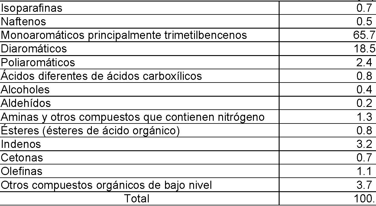
Tabla 8Table 8

Se realizó un análisis similar, pero sin el uso de los miembros 4 cruzados en la cámara 9 de reacción. Los resultados se muestran en la Tabla 9. A similar analysis was performed, but without the use of the cross members 4 in reaction chamber 9. The results are shown in Table 9.
Tabla 9Table 9

Los experimentos muestran que la mayoría de las materias primas utilizadas en la presente invención producirán aceites útiles que tienen aproximadamente la siguiente composición que se muestra en la Tabla 10.Experiments show that most of the raw materials used in the present invention will produce useful oils having approximately the following composition shown in Table 10.
Tabla 10Table 10

Por tanto, las realizaciones preferidas pueden proporcionar un aceite elaborado a partir de compuestos de pirólisis que se han sometido a electrólisis, y compuestos elaborados en un proceso de arco eléctrico de gas a líquidos. Se considera que la composición de la materia prima es el principal impulsor (no exclusivo) del contenido de parafinas y olefinas. Las ineficiencias en este proceso de electrólisis pueden producir alcoholes, ácidos, fenoles y nitrilos. La operación de gas a líquido del proceso de arco eléctrico descrito anteriormente produce aromáticos, aminas, amidas, cetonas, indenos; la composición de cada uno depende de la cantidad de gas convertido en líquido en gas de arco eléctrico. Las isoparafinas preferentemente estarán en el rango de 0.2 a 15 por ciento en peso, más preferentemente, 0.3 a 10 por ciento en peso, incluso más preferentemente, 0.4 a 7 por ciento en peso, todavía más preferentemente, 0.5 a 4 por ciento en peso, incluso más preferentemente, 0.6 a 1 por ciento en peso, aún más preferentemente, 0.7 por ciento en peso. Los nafténicos preferentemente estarán en el rango de 0.1 a 15 por ciento en peso, más preferentemente, 0.2 a 10 por ciento en peso, incluso más preferentemente, 0.3 a 5 por ciento en peso, todavía más preferentemente, 0.4 a 1 por ciento en peso, aún más preferentemente, 0.5 por ciento en peso. Los monoaromáticos preferentemente estarán en el rango de 3 a 75 por ciento en peso, más preferentemente, 10 a 73 por ciento en peso, incluso más preferentemente, 30 a 71 por ciento en peso, todavía más preferentemente, 50 a 69 por ciento en peso, incluso más preferentemente, 60 a 67 por ciento en peso, aún más preferentemente, 65 por ciento en peso. Los diaromáticos preferentemente estarán en el rango de 0 a 40 por ciento en peso, más preferentemente, 5 a 35 por ciento en peso, incluso más preferentemente, 10 a 30 por ciento en peso, todavía más preferentemente, 12 a 25 por ciento en peso, incluso más preferentemente, 14 a 20 por ciento en peso, aún más preferentemente, 18 por ciento en peso. Los poliaromáticos preferentemente estarán en el rango de 0 a 15 por ciento en peso, más preferentemente, 0.5 a 10 por ciento en peso, incluso más preferentemente, 1 a 7 por ciento en peso, todavía más preferentemente, 1.5 a 4 por ciento en peso, incluso más preferentemente, 2 a 3 por ciento en peso, aún más preferentemente, 2.4 por ciento en peso. Los alcoholes preferentemente estarán en el rango de 0 a 15 por ciento en peso, más preferentemente, 0.1 a 10 por ciento en peso, incluso más preferentemente, 0.2 a 5 por ciento en peso, todavía más preferentemente, 0.3 a 2 por ciento en peso, aún más preferentemente, 0.4 por ciento en peso. Los aldehídos preferentemente estarán en el rango de 0.1 a 3 por ciento en peso, más preferentemente, 0.3 a 10 por ciento en peso, incluso más preferentemente, 0.4 a 7 por ciento en peso, todavía más preferentemente, 0.5 a 4 por ciento en peso, incluso más preferentemente, 0.6 a 1 por ciento en peso, aún más preferentemente, 0.7 por ciento en peso. Las aminas preferentemente estarán en el rango de 0.1 a 7 por ciento en peso, más preferentemente, 0.4 a 5 por ciento en peso, incluso más preferentemente, 0.7 a 3 por ciento en peso, todavía más preferentemente, 1.0 a 2 por ciento en peso, incluso más preferentemente, 1.1 a 1.5 por ciento en peso, aún más preferentemente, 1.3 por ciento en peso. Los ésteres preferentemente estarán en el rango de 0.1 a 3 por ciento en peso, más preferentemente, 0.3 a 2.5 por ciento en peso, incluso más preferentemente, 0.5 a 2 por ciento en peso, todavía más preferentemente, 0.6 a 1.5 por ciento en peso, incluso más preferentemente, 0.7 a 1 por ciento en peso, aún más preferentemente, 0.8 por ciento en peso. Los indenos preferentemente estarán en el rango de 0.1 a 7 por ciento en peso, más preferentemente, 0.5 a 6 por ciento en peso, incluso más preferentemente, 1 a 5 por ciento en peso, todavía más preferentemente, 1.5 a 4.5 por ciento en peso, incluso más preferentemente, 2 a 4 por ciento en peso, aún más preferentemente, 3.2 por ciento en peso. Las cetonas preferentemente estarán en el rango de 0.1 a 7 por ciento en peso, más preferentemente, 0.2 a 6 por ciento en peso, incluso más preferentemente, 0.3 a 5 por ciento en peso, todavía más preferentemente, 0.4 a 3 por ciento en peso, incluso más preferentemente, 0.5 a 1 por ciento en peso, aún más preferentemente, 0.7 por ciento en peso. Las olefinas preferentemente estarán en el rango de 0.1 a 30 por ciento en peso, más preferentemente, 0.4 a 20 por ciento en peso, incluso más preferentemente, 0.6 a 10 por ciento en peso, todavía más preferentemente, 0.8 a 5 por ciento en peso, incluso más preferentemente, 0.9 a 2 por ciento en peso, aún más preferentemente, 1.1 por ciento en peso. Thus, preferred embodiments can provide an oil made from pyrolysis compounds that have undergone electrolysis, and compounds made in a gas-to-liquid electric arc process. The composition of the feedstock is considered to be the main (non-exclusive) driver of paraffin and olefin content. Inefficiencies in this electrolysis process can produce alcohols, acids, phenols, and nitriles. The gas-to-liquid operation of the electric arc process described above produces aromatics, amines, amides, ketones, indens; the composition of each depends on the amount of gas converted to liquid into electric arc gas. The isoparaffins will preferably be in the range 0.2 to 15 weight percent, more preferably 0.3 to 10 weight percent, even more preferably 0.4 to 7 weight percent, still more preferably 0.5 to 4 weight percent even more preferably 0.6 to 1 weight percent, still more preferably 0.7 weight percent. Naphthenics will preferably be in the range 0.1 to 15 weight percent, more preferably 0.2 to 10 weight percent, even more preferably 0.3 to 5 weight percent, still more preferably 0.4 to 1 weight percent even more preferably 0.5 weight percent. Monoaromatics will preferably be in the range of 3 to 75 weight percent, more preferably 10 to 73 weight percent, even more preferably 30 to 71 weight percent, still more preferably 50 to 69 weight percent even more preferably 60 to 67 percent by weight, even more preferably 65 percent by weight. The diaromatics will preferably be in the range of 0 to 40 weight percent, more preferably 5 to 35 weight percent, even more preferably 10 to 30 weight percent, still more preferably 12 to 25 weight percent even more preferably 14 to 20 percent by weight, even more preferably 18 percent by weight. The polyaromatics will preferably be in the range of 0 to 15 percent by weight, more preferably 0.5 to 10 percent by weight, even more preferably, 1 to 7 percent by weight, still more preferably, 1.5 to 4 percent by weight, even more preferably, 2 to 3 percent by weight, even more preferably, 2.4 percent in weigh. The alcohols will preferably be in the range of 0 to 15 weight percent, more preferably 0.1 to 10 weight percent, even more preferably 0.2 to 5 weight percent, still more preferably 0.3 to 2 weight percent , even more preferably, 0.4 weight percent. The aldehydes will preferably be in the range of 0.1 to 3 percent by weight, more preferably 0.3 to 10 percent by weight, even more preferably 0.4 to 7 percent by weight, still more preferably 0.5 to 4 percent by weight. even more preferably 0.6 to 1 weight percent, still more preferably 0.7 weight percent. The amines will preferably be in the range 0.1 to 7 weight percent, more preferably 0.4 to 5 weight percent, even more preferably 0.7 to 3 weight percent, still more preferably 1.0 to 2 weight percent even more preferably 1.1 to 1.5 weight percent, still more preferably 1.3 weight percent. The esters will preferably be in the range of 0.1 to 3 percent by weight, more preferably 0.3 to 2.5 percent by weight, even more preferably 0.5 to 2 percent by weight, still more preferably 0.6 to 1.5 percent by weight. even more preferably 0.7 to 1 percent by weight, even more preferably 0.8 percent by weight. The indenes will preferably be in the range 0.1 to 7 weight percent, more preferably 0.5 to 6 weight percent, even more preferably 1 to 5 weight percent, still more preferably 1.5 to 4.5 weight percent even more preferably 2 to 4 weight percent, still more preferably 3.2 weight percent. Ketones will preferably be in the range 0.1 to 7 weight percent, more preferably 0.2 to 6 weight percent, even more preferably 0.3 to 5 weight percent, still more preferably 0.4 to 3 weight percent even more preferably 0.5 to 1 percent by weight, even more preferably 0.7 percent by weight. The olefins will preferably be in the range of 0.1 to 30 percent by weight, more preferably 0.4 to 20 percent by weight, even more preferably 0.6 to 10 percent by weight, still more preferably 0.8 to 5 percent by weight. even more preferably 0.9 to 2 weight percent, even more preferably 1.1 weight percent.
El aceite de acuerdo con las realizaciones preferidas muestra por tanto una mezcla única de compuestos altamente complejos que no se encuentran normalmente en el aceite crudo natural o en productos tales como los aceites de Fischer-Tropsch, pero tiene compuestos que comúnmente son artificiales. De forma notable los ácidos orgánicos que se observan en los aceites de pirólisis, tales como el levoglucasan y ácido acético, y xilano, están ausentes del análisis, o solo en pequeñas cantidades.The oil according to the preferred embodiments thus exhibits a unique blend of highly complex compounds that are not normally found in natural crude oil or in products such as Fischer-Tropsch oils, but have compounds that are commonly artificial. Notably, the organic acids seen in pyrolysis oils, such as levoglucasan and acetic acid, and xylan, are absent from the analysis, or only in small amounts.
Las propiedades del ARK OIL™ producido de esta manera se pueden ajustar al agregar ciertos aditivos a los desperdicios de desechos antes de la pirólisis. Los aditivos incluyen Arnosoak, un agente patentado modificador de desperdicios y/o virutas de madera. La cantidad de Arnosoak incorporada a los desperdicios puede ser de aproximadamente 0.1 % a aproximadamente 40 % en peso de los desperdicios secos, más preferentemente de aproximadamente 1 % a aproximadamente 20 % en peso de los desperdicios secos. Por tanto, Arnosoak se puede utilizar para controlar el pH del aceite. El pH del aceite sin tratar puede variar entre 6 y 8, pero con la adición de Arnosoak, el rango de pH del aceite se puede reducir hasta 4, dependiendo de la cantidad de Arnosoak agregado a los desperdicios antes de la pirólisis. Se puede proporcionar la adición de un solvente al aceite para un mejor almacenamiento. En determinadas realizaciones, el solvente agregado al aceite es etanol, metanol, acetona o agua. Cuando se agregan, los solventes se pueden agregar a una concentración de aproximadamente 1 % a aproximadamente 10 % en peso del aceite, con una concentración preferida de 10 % en peso de aceite.The properties of ARK OIL ™ produced in this way can be adjusted by adding certain additives to the waste waste prior to pyrolysis. Additives include Arnosoak, a proprietary waste and / or wood chip modifying agent. The amount of Arnosoak incorporated into the waste can be from about 0.1% to about 40% by weight of the dry waste, more preferably from about 1% to about 20% by weight of the dry waste. Therefore, Arnosoak can be used to control the pH of the oil. The pH of the raw oil can vary between 6 and 8, but with the addition of Arnosoak, the pH range of the oil can be reduced to 4, depending on the amount of Arnosoak added to the waste before pyrolysis. The addition of a solvent to the oil can be provided for better storage. In certain embodiments, the solvent added to the oil is ethanol, methanol, acetone, or water. When added, the solvents can be added at a concentration of from about 1% to about 10% by weight of the oil, with a preferred concentration of 10% by weight of the oil.
ARK SOIL™. El fertilizante de cenizas producido de acuerdo con la presente invención (denominado ARK SOIL™) también tiene una firma única que lo hace atractivo como fertilizante orgánico para todo uso. Este fertilizante de cenizas reducirá el volumen transportado y los costes de transporte asociados con los desechos animales utilizados como fertilizante. El fertilizante de cenizas de acuerdo con la presente invención contiene un valor nutricional similar para cultivos agrícolas sin ninguna amenaza biológica o química planteada por los desechos crudos. El Laboratorio de Diagnóstico Agrícola de la Universidad de Arkansas en Fayetteville llevó a cabo un análisis del fertilizante. Los resultados se muestran a continuación en la Tabla 11. Otros análisis de ARK SOIL™ han mostrado un contenido de carbono del 46 por ciento. Preferentemente, el fertilizante de acuerdo con la presente invención tendrá un alto contenido de nitrógeno, en el rango de 0.1 a 3 por ciento en peso, más preferentemente, 0.3 a 5 por ciento en peso, incluso más preferentemente, 0.6 a 4 por ciento en peso, todavía más preferentemente, 0.8 a 3 por ciento en peso, incluso más preferentemente, 1 a 2 por ciento en peso, aún más preferentemente, 1.2 por ciento en peso.ARK SOIL ™. The ash fertilizer produced in accordance with the present invention (referred to as ARK SOIL ™) also has a unique signature that makes it attractive as an all-purpose organic fertilizer. This ash fertilizer will reduce the volume transported and the transport costs associated with animal waste used as fertilizer. The ash fertilizer according to the present invention contains similar nutritional value for agricultural crops without any biological or chemical threat posed by raw waste. The Agricultural Diagnostic Laboratory at the University of Arkansas in Fayetteville carried out an analysis of the fertilizer. The results are shown in Table 11 below. Other analyzes of ARK SOIL ™ have shown a carbon content of 46 percent. Preferably, the fertilizer according to the present invention will have a high nitrogen content, in the range 0.1 to 3 percent by weight, more preferably 0.3 to 5 percent by weight, even more preferably 0.6 to 4 percent by weight. weight, still more preferably 0.8 to 3 weight percent, even more preferably 1 to 2 weight percent, even more preferably 1.2 weight percent.
Tabla 11Table 11

continuacióncontinuation

Se han realizado estudios de balance de masa-energía en la presente invención, con los resultados que se muestran a continuación en la Tabla 12. Mass-energy balance studies have been performed on the present invention, with the results shown below in Table 12.


Los experimentos muestran que el reformador de la presente invención puede proporcionar la siguiente producción: 2000 libras de materia prima (1 tonelada) producirán aproximadamente 6.4 barriles de petróleo más aproximadamente 63,000 pies cúbicos de gas de síntesis más aproximadamente 60 libras de fertilizante de cenizas. Básicamente, un balde de 5 galones de desechos de pollos producirá un balde de 5 galones de aceite (además del gas y el fertilizante).Experiments show that the reformer of the present invention can provide the following output: 2000 pounds of feedstock (1 ton) will produce about 6.4 barrels of oil plus about 63,000 cubic feet of syngas plus about 60 pounds of ash fertilizer. Basically a 5 gallon bucket of chicken waste will produce a 5 gallon bucket of oil (plus gas and fertilizer).
6. Conclusión6. Conclusion
Por lo tanto, la presente tecnología de reforma transforma cualquier material de desecho a base de carbono a nivel atómico para producir un alto volumen de petróleo parcialmente refinado (con poco o nada de azufre), un gas de síntesis rico en hidrógeno y una ceniza sólida que se clasifica como fertilizante por el Departamento de Agricultura de los Estados Unidos. Hay pocas o ninguna emisión fugitiva dañina. La tecnología es una fracción del tamaño y el coste de las tecnologías existentes de conversión de residuos en energía o de residuos en combustible, y produce un volumen mucho mayor de valiosos productos energéticos. La tecnología del reformador en cuestión proporciona un proceso continuo de baja presión y bajo calor que separa y reforma los elementos orgánicos básicos que se encuentran en el material de desecho en petróleo parcialmente refinado de alto valor. Las instalaciones de producción de aceite de acuerdo con la presente invención tienen costes operativos intrínsecamente bajos, costes de capital bajos y alta eficiencia. Cada reformador puede proporcionar el método más económico de transformar material orgánico común en hidrocarburos valiosos que están listos para la refinería, tienen una relación de hidrógeno a monóxido de carbono de aproximadamente 2.2:1 y tienen un azufre mínimo o nulo. La eficiencia de conversión de materia prima para 100 toneladas de materia prima produce más valor que 1000 toneladas procesadas por tecnologías de gasificación o pirólisis existentes. Se puede utilizar desperdicio de aves, estiércol de caballo, estiércol de vaca, llantas trituradas, desechos de madera, pasto, desechos de cafetería, cáscaras de arroz, polvo de lijado de tableros de fibra de densidad Media (MDF) (con agua agregada), lignito, cenizas de gasificador y desechos sólidos municipales como materia prima para el reformador de la presente invención con éxito. Además, se pueden combinar varias materias primas en varios porcentajes para proporcionar incluso más aceites, gases y fertilizantes manipulados. Se estima que el coste de producción de un barril de petróleo de acuerdo con la presente invención será de aproximadamente USD$20-25 dólares estadounidenses, lo que se compara muy favorablemente con otras formas de producción de petróleo. La presente invención produce hidrocarburos, tales como alifáticos, parafinas, aromáticos, productos químicos especiales, combustibles y aditivos de combustible y aceite. El aceite crudo sintético de acuerdo con las realizaciones preferidas no contiene virtualmente azufre.Therefore, the present reforming technology transforms any carbon-based waste material at the atomic level to produce a high volume of partially refined oil (with little or no sulfur), a hydrogen-rich syngas and a solid ash. It is classified as a fertilizer by the United States Department of Agriculture. There are few or no harmful fugitive emissions. The technology is a fraction of the size and cost of existing waste-to-energy or waste-to-fuel technologies, and produces a much larger volume of valuable energy products. The reformer technology in question provides a continuous low pressure, low heat process that separates and reforms the basic organic elements found in waste material into high value partially refined petroleum. Oil production facilities according to the present invention have inherently low operating costs, low capital costs and high efficiency. Each reformer can provide the most economical method of transforming common organic material into valuable hydrocarbons that are refinery ready, have a hydrogen to carbon monoxide ratio of approximately 2.2: 1, and have little or no sulfur. The raw material conversion efficiency for 100 tonnes of raw material produces more value than 1000 tonnes processed by existing gasification or pyrolysis technologies. Poultry waste, horse manure, cow manure, shredded tires, wood waste, grass, cafeteria waste, rice husks, Medium Density Fiberboard (MDF) sanding dust (with added water) can be used , lignite, gasifier ash and municipal solid waste as feedstock for the reformer of the present invention successfully. Additionally, various raw materials can be combined in various percentages to provide even more engineered oils, gases and fertilizers. The cost of producing a barrel of oil in accordance with the present invention is estimated to be approximately US $ 20-25, which compares very favorably with other forms of oil production. The present invention produces hydrocarbons, such as aliphatics, paraffins, aromatics, specialty chemicals, fuels, and fuel and oil additives. The synthetic crude oil according to preferred embodiments contains virtually no sulfur.
Los componentes individuales mostrados en contorno o designados por bloques en los Dibujos adjuntos son todos bien conocidos en las técnicas de gasificación/refinado, y su construcción y operación específicas no son críticas para la operación o el mejor modo para llevar a cabo la invención.The individual components shown in outline or designated by blocks in the accompanying Drawings are all well known in the gasification / refining arts, and their specific construction and operation are not critical to the operation or the best mode for carrying out the invention.
Aunque la presente invención se ha descrito con respecto a lo que actualmente se considera que son las realizaciones preferidas, se debe entender que la invención no se limita a las realizaciones divulgadas. Although the present invention has been described with respect to what are presently considered to be the preferred embodiments, it should be understood that the invention is not limited to the disclosed embodiments.
Claims (13)
Applications Claiming Priority (2)
| Application Number | Priority Date | Filing Date | Title |
|---|---|---|---|
| US201461986997P | 2014-05-01 | 2014-05-01 | |
| PCT/US2014/050126 WO2015167596A1 (en) | 2014-05-01 | 2014-08-07 | Apparatus and method for conversion of solid waste into synthetic oil, gas and fertilizer |
Publications (1)
| Publication Number | Publication Date |
|---|---|
| ES2821385T3 true ES2821385T3 (en) | 2021-04-26 |
Family
ID=51453842
Family Applications (1)
| Application Number | Title | Priority Date | Filing Date |
|---|---|---|---|
| ES14758198T Active ES2821385T3 (en) | 2014-05-01 | 2014-08-07 | Apparatus for the conversion of solid waste into synthetic oil, gas and fertilizer |
Country Status (7)
| Country | Link |
|---|---|
| US (4) | US9005536B1 (en) |
| EP (1) | EP3137585B1 (en) |
| CN (1) | CN107075384A (en) |
| DK (1) | DK3137585T3 (en) |
| ES (1) | ES2821385T3 (en) |
| PL (1) | PL3137585T3 (en) |
| WO (1) | WO2015167596A1 (en) |
Families Citing this family (16)
| Publication number | Priority date | Publication date | Assignee | Title |
|---|---|---|---|---|
| US9409828B1 (en) * | 2014-02-07 | 2016-08-09 | Leo Byford | Method for treating animal waste and other waste streams |
| US11566211B2 (en) * | 2014-10-22 | 2023-01-31 | Gsr Solutions, Llc | Systems and methods of producing compositions from the nutrients recovered from waste streams |
| EP3334805B1 (en) * | 2015-08-13 | 2019-05-15 | Shell International Research Maatschappij B.V. | Process for fuel formulation |
| US10787362B2 (en) * | 2016-05-16 | 2020-09-29 | Christopher L. de Graffenried, SR. | Hydrogen co-firing with carbon pre-capture for higher carbon ratio fossil fuels |
| CN106000990A (en) * | 2016-06-13 | 2016-10-12 | 安庆市凯立金刚石科技有限公司 | Airflow-flushing type diamond pickling device |
| CN105880210A (en) * | 2016-06-13 | 2016-08-24 | 安庆市凯立金刚石科技有限公司 | Airflow-flushing and precipitation-preventing pickling device |
| CN105950223A (en) * | 2016-06-29 | 2016-09-21 | 姚姝 | Ash discharging mechanism of gasifier |
| US20180111109A1 (en) * | 2016-10-24 | 2018-04-26 | Michael W. Rogers | Method, apparatus, and computer-readable media for vortex arc reactor |
| CN108335978B (en) * | 2017-01-20 | 2022-08-26 | 东京毅力科创株式会社 | Plasma processing apparatus |
| JPWO2019151461A1 (en) * | 2018-02-05 | 2021-02-12 | 三菱瓦斯化学株式会社 | Biomass gasification power generation system and power generation method |
| CN110846080A (en) * | 2019-11-25 | 2020-02-28 | 大唐东北电力试验研究院有限公司 | Biomass positive-pressure circulating fluidized bed gasification furnace fly ash cooling system |
| CN112178912B (en) * | 2020-10-09 | 2021-12-14 | 北京绿洲德瀚环境保护中心有限责任公司 | Waste heat recovery energy-saving boiler |
| CN112178913B (en) * | 2020-10-09 | 2022-05-31 | 薄涛 | Biomass combustion furnace heating system |
| CN112178911B (en) * | 2020-10-09 | 2022-06-07 | 丰宁满族自治县万泰能源科技有限公司 | Biomass particle heating furnace |
| RU2760216C1 (en) * | 2021-02-09 | 2021-11-22 | Федеральное государственное бюджетное образовательное учреждение высшего образования "Южно-Уральский государственный аграрный университет" (ФГБОУ ВО Южно-Уральский ГАУ) | Method for deep processing of poultry manure |
| CN116611614B (en) * | 2023-05-17 | 2023-10-13 | 南京邮电大学 | Commercial tenant meal-outlet management method and system based on big data platform |
Family Cites Families (40)
| Publication number | Priority date | Publication date | Assignee | Title |
|---|---|---|---|---|
| US3333927A (en) | 1963-07-22 | 1967-08-01 | Avco Corp | Electrothermal process for producing acetylene and carbon black |
| US4472172A (en) | 1979-12-03 | 1984-09-18 | Charles Sheer | Arc gasification of coal |
| NZ203822A (en) | 1982-04-29 | 1985-04-30 | British Petroleum Co Plc | Process for converting hydrocarbon feedstock to aromatic hydrocarbons |
| US4583992A (en) | 1984-12-04 | 1986-04-22 | Buck Rogers Mfg. Co., Inc. | Biomass gasifier and charcoal producer |
| US5417817A (en) * | 1994-06-15 | 1995-05-23 | Dammann; Wilbur A. | Biomass gasification process and apparatus |
| US6238543B1 (en) | 1997-10-17 | 2001-05-29 | E. I. Du Pont De Nemours And Company | Kolbe electrolysis in a polymer electrolyte membrane reactor |
| US6130260A (en) | 1998-11-25 | 2000-10-10 | The Texas A&M University Systems | Method for converting natural gas to liquid hydrocarbons |
| AUPQ314399A0 (en) * | 1999-09-29 | 1999-10-21 | World Oasis Australia Pty Ltd | Process for recovering energy from carbon-containing materials |
| JP2003528208A (en) | 2000-03-23 | 2003-09-24 | ウエストバージニア ユニバーシティ | Method for converting agricultural waste to liquid fuel and related equipment |
| US7387712B2 (en) | 2002-10-17 | 2008-06-17 | Carnegie Mellon University | Catalytic process for the treatment of organic compounds |
| US6903259B2 (en) * | 2002-12-06 | 2005-06-07 | Arvin Technologies, Inc. | Thermoelectric device for use with fuel reformer and associated method |
| US8877992B2 (en) | 2003-03-28 | 2014-11-04 | Ab-Cwt Llc | Methods and apparatus for converting waste materials into fuels and other useful products |
| EP1615862A4 (en) | 2003-03-28 | 2011-06-15 | Cwt Llc Ab | Process and apparatus for conversion of organic, waste, or low-value materials into useful products |
| US7301060B2 (en) | 2003-03-28 | 2007-11-27 | Ab-Cwt, Llc | Process for conversion of organic, waste, or low-value materials into useful products |
| US7438987B2 (en) | 2003-05-15 | 2008-10-21 | Lawrence Livermore National Security, Llc | Carbon fuel particles used in direct carbon conversion fuel cells |
| US7964026B2 (en) | 2003-08-04 | 2011-06-21 | Power Reclamation, Inc. | Gasification apparatus |
| US20050268556A1 (en) | 2003-08-04 | 2005-12-08 | Power Reclamation, Inc. | Gasification apparatus and method |
| MX336111B (en) | 2005-10-17 | 2016-01-08 | Cwt Llc Ab | Process of conversion of organic and non-organic waste materials into useful products. |
| CA2586311A1 (en) | 2006-04-28 | 2007-10-28 | Thermalco Inc. | Apparatus and method for conversion of animal litter biomass into useful energy |
| US8529646B2 (en) | 2006-05-01 | 2013-09-10 | Lpp Combustion Llc | Integrated system and method for production and vaporization of liquid hydrocarbon fuels for combustion |
| US7808227B2 (en) * | 2006-07-07 | 2010-10-05 | Univation Technologies, Llc | Systems and methods for detecting impurities in reactor systems |
| CA2716913C (en) * | 2007-02-27 | 2014-09-09 | Plasco Energy Group Inc. | A multi-zone carbon conversion system with plasma melting |
| US20140011104A1 (en) * | 2007-06-26 | 2014-01-09 | The Board Of Trustees Of The Leland Stanford Junior University | Integrated Dry Gasification Fuel Cell System for Conversion of Solid Carbonaceous Fuels |
| WO2009018543A1 (en) | 2007-08-01 | 2009-02-05 | Virginia Tech Intellectual Properties, Inc. | Thermochemical method for conversion of poultry litter |
| US7981563B2 (en) | 2007-11-26 | 2011-07-19 | Gas Technology Institute | Direct carbon fuel cell with pre-wetted carbon particles |
| JP5366147B2 (en) * | 2008-02-05 | 2013-12-11 | 一般財団法人電力中央研究所 | Fuel gas purification equipment, power generation system and fuel synthesis system |
| DE102009023457B4 (en) * | 2009-06-02 | 2011-05-19 | Lurgi Gmbh | Process and apparatus for gasifying baking coal |
| WO2011106285A1 (en) | 2010-02-23 | 2011-09-01 | Greatpoint Energy, Inc. | Integrated hydromethanation fuel cell power generation |
| US8652696B2 (en) | 2010-03-08 | 2014-02-18 | Greatpoint Energy, Inc. | Integrated hydromethanation fuel cell power generation |
| US8372251B2 (en) * | 2010-05-21 | 2013-02-12 | General Electric Company | System for protecting gasifier surfaces from corrosion |
| CA2807469A1 (en) * | 2010-08-03 | 2012-02-09 | Xiaodi Huang | Method and apparatus for coproduction of pig iron and high quality syngas |
| GB201014304D0 (en) * | 2010-08-27 | 2010-10-13 | Akay Galip | Intensified integrated biomass-to-energy carrier conversion process |
| US20120061618A1 (en) * | 2010-09-11 | 2012-03-15 | James Santoianni | Plasma gasification reactors with modified carbon beds and reduced coke requirements |
| FR2965816B1 (en) | 2010-10-12 | 2014-04-25 | S3D | DEVICE FOR TRANSFORMING A FUEL |
| US9321640B2 (en) * | 2010-10-29 | 2016-04-26 | Plasco Energy Group Inc. | Gasification system with processed feedstock/char conversion and gas reformulation |
| WO2012106298A1 (en) | 2011-02-01 | 2012-08-09 | Joshi Chandrashekhar H | Production of hydrocarbon fuels from plant oil and animal fat |
| TW201241367A (en) * | 2011-04-01 | 2012-10-16 | Suncue Co Ltd | Material poking control method for combustion apparatus and device thereof |
| US8100990B2 (en) | 2011-05-15 | 2012-01-24 | Avello Bioenery, Inc. | Methods for integrated fast pyrolysis processing of biomass |
| US11479727B2 (en) | 2011-11-04 | 2022-10-25 | Thermochem Recovery International, Inc. | System and method for flexible conversion of feedstock to oil and gas |
| US9074151B2 (en) * | 2012-09-28 | 2015-07-07 | Adaptivearc, Inc. | Plasma assisted gasification system with an indirect vacuum system |
-
2014
- 2014-08-07 WO PCT/US2014/050126 patent/WO2015167596A1/en active Application Filing
- 2014-08-07 PL PL14758198T patent/PL3137585T3/en unknown
- 2014-08-07 ES ES14758198T patent/ES2821385T3/en active Active
- 2014-08-07 CN CN201480080330.4A patent/CN107075384A/en active Pending
- 2014-08-07 EP EP14758198.7A patent/EP3137585B1/en active Active
- 2014-08-07 DK DK14758198.7T patent/DK3137585T3/en active
- 2014-08-07 US US14/454,414 patent/US9005536B1/en active Active
-
2015
- 2015-02-12 US US14/620,774 patent/US9057029B1/en active Active
- 2015-05-07 US US14/706,504 patent/US9765268B2/en active Active
-
2017
- 2017-09-12 US US15/701,899 patent/US10808190B2/en active Active
Also Published As
| Publication number | Publication date |
|---|---|
| DK3137585T3 (en) | 2020-09-28 |
| US10808190B2 (en) | 2020-10-20 |
| EP3137585B1 (en) | 2020-07-01 |
| CN107075384A (en) | 2017-08-18 |
| WO2015167596A1 (en) | 2015-11-05 |
| US20150315475A1 (en) | 2015-11-05 |
| US20180086993A1 (en) | 2018-03-29 |
| US9057029B1 (en) | 2015-06-16 |
| PL3137585T3 (en) | 2021-04-19 |
| US9765268B2 (en) | 2017-09-19 |
| EP3137585A1 (en) | 2017-03-08 |
| US9005536B1 (en) | 2015-04-14 |
Similar Documents
| Publication | Publication Date | Title |
|---|---|---|
| ES2821385T3 (en) | Apparatus for the conversion of solid waste into synthetic oil, gas and fertilizer | |
| Hrnčič et al. | Hydrothermal treatment of biomass for energy and chemicals | |
| Lee et al. | Recent progress in the catalytic thermochemical conversion process of biomass for biofuels | |
| Arun et al. | Hydrothermal liquefaction of Scenedesmus obliquus using a novel catalyst derived from clam shells: Solid residue as catalyst for hydrogen production | |
| CN101827645B (en) | Process and apparatus for converting organic matter into a product | |
| Mohammad et al. | Pyrolysis of Napier grass in a fixed bed reactor: effect of operating conditions on product yields and characteristics | |
| Gonzalez et al. | Pyrolysis of almond shells. Energy applications of fractions | |
| Parthasarathy et al. | Combined slow pyrolysis and steam gasification of biomass for hydrogen generation—a review | |
| Mishra et al. | Pyrolysis of Manilkara zapota seeds over ZSM-5 to produce high-quality bio-oil and chemicals | |
| CN105229123B (en) | Stage biomass fractionator | |
| BR112013029457B1 (en) | FRACTIONING AND FAST PYROLYSIS METHOD OF INTEGRATED BIOMASS | |
| ES2920723T3 (en) | Ballistic heating process | |
| US20110232160A1 (en) | Biomass conversion process | |
| WO2013015930A1 (en) | Method for producing negative carbon fuel | |
| CA2748985A1 (en) | Method for processing organic waste and a device for carrying out said method | |
| Alherbawi et al. | Potential of drop-in biofuel production from camel manure by hydrothermal liquefaction and biocrude upgrading: A Qatar case study | |
| Faizan et al. | Critical review on catalytic biomass gasification: State-of-Art progress, technical challenges, and perspectives in future development | |
| Taufer et al. | Coupling hydrothermal carbonization of digestate and supercritical water gasification of liquid products | |
| Babatabar et al. | Pyrolysis of lignocellulosic and algal biomasses in a fixed‐bed reactor: A comparative study on the composition and application potential of bioproducts | |
| Chaudhary et al. | Slow pyrolysis of low-density Poly-Ethylene (LDPE): A batch experiment and thermodynamic analysis | |
| Song et al. | Thermal analysis technology to utilize waste biomass and waste heat to produce high-quality combustible gas through simulations and experiments | |
| WO2019197937A1 (en) | Method for producing fuel from carbon-containing material | |
| Mulimani et al. | Production and Characterization of Bio‐Oil by Pyrolysis of Mahua De‐Oiled Seed Cake | |
| Amrullah et al. | Conversion and rate behavior of brown macroalgae in pyrolysis: Detailed effects of operating parameters | |
| Beneroso et al. | Microwave technology for syngas production from renewable sources |